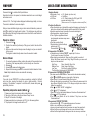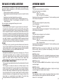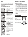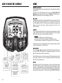
1
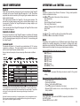
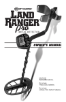
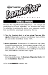
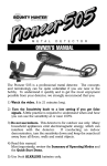
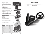
ACCESSORIES
Bounty Hunter Carry Bag
®
Rugged double-stitched construction. – CBAG2
Bounty Hunter Pouch & Digger Combo
®
Pouch with 2 large pockets & 9” heavy duty digging tool. – TP-KIT-W
Pinpointer
Pinpoints the exact location of buried metal objects. Audio signal indicator
and vibrator. Runs on (1) 9-Volt Alkaline battery. – PIN POINTER-W
Bounty Hunter Sand Scoop
®
Large scoop with filtering holes. Made of strong plastic. – SAND SCOOPBH
Replacement/Accessory Searchcoils
4”
8”
10”
11”
Concentric Round – 4COILPRO
Concentric Open Face Accessory Coil – 8COIL-7B13
Concentric Replacement Coil – 10COIL-BH
Biaxial Standard Coil – 11COIL-BH
METAL DETECTOR
Searchcoil Covers
Protect your coil from abrasion and damage.
4” Concentric, Round Cover– 4COVER
8” Concentric Open Face Accessory Coil Cover – 8COVER-7
10” Concentric Coil Cover – F70COVER
11” Biaxial Standard Coil Cover – COVER-11DD
OWNER’S MANUAL
9” Heavy-Duty Digging Tool
Metal blade with comfortable plastic handle and depth gauge. – TROWEL-2
Digging Tool
Light and practical plastic, wide blade digging tool. – TROWEL-W
Rain Cover
Custom made to protect from weather. – RAINCOV-ET
Bounty Hunter Baseball Cap
®
One size fits all, with Bounty Hunter® logo. – BHCAP
Bounty Hunter T-Shirt
®
100% cotton with Bounty Hunter® Logo.
Sizes: S, M, LG, XL & XXL – BHTSHIRT
Gold
Prospecting Kits
Use 9-volt
ALKALINE batteries.
Do not use
“Heavy Duty” batteries.
Do not use
ordinary “Zinc Carbon” batteries.
FOR COMPLETE DETAILS VISIT WWW.DETECTING.COM • 1-800-413-4131
MPROLR
080414
TREASURE HUNTER’S CODE OF ETHICS:
Congratulations!
Congratulations on the purchase of your new Bounty Hunter Land Ranger
Pro Metal Detector. The Land Ranger Pro is the result of nine years of software
engineering and features the latest advancements in lightweight design, target
accuracy and deep-penetrating detection technology.
®
™
The Land Ranger Pro can be used with its default turn-on-and-go settings or it
can be customized for any of your treasure hunting applications with its unique
features like Enhanced V-Break®, High Resolution Conductivity Arc and
Program Memory, as well as Manual and Automatic Search Modes. Treasure
hunting enthusiasts from around the world were involved in the development
of this revolutionary new detector. This manual has been written to help you
get optimal use of your detector so we hope you will read it thoroughly before
your first outing.
Happy Hunting from First Texas Products!
TABLE OF CONTENTS
Terminology . . . . . . . . . . . . . . . . . . . . . . . . . . . . . . . . . . . . . . . . . . . . . . . . . . . . . . . .3
Contents . . . . . . . . . . . . . . . . . . . . . . . . . . . . . . . . . . . . . . . . . . . . . . . . . . . . . . . . . . .4
Assembly . . . . . . . . . . . . . . . . . . . . . . . . . . . . . . . . . . . . . . . . . . . . . . . . . . . . . . . . . .5
Batteries (use alkaline batteries only) . . . . . . . . . . . . . . . . . . . . . . . . . . . . . . . . . . . .6
Quick-Start Demonstration . . . . . . . . . . . . . . . . . . . . . . . . . . . . . . . . . . . . . . . . . . . . .7
The Basics of Metal Detecting . . . . . . . . . . . . . . . . . . . . . . . . . . . . . . . . . . . . . . . .8-9
How to Work the Controls . . . . . . . . . . . . . . . . . . . . . . . . . . . . . . . . . . . . . . . . . . . .10
The Display . . . . . . . . . . . . . . . . . . . . . . . . . . . . . . . . . . . . . . . . . . . . . . . . . . . . . . . .11
Target Identification . . . . . . . . . . . . . . . . . . . . . . . . . . . . . . . . . . . . . . . . . . . . . . . . . .12
Operation and Control . . . . . . . . . . . . . . . . . . . . . . . . . . . . . . . . . . . . . . . . . . . . . . .13
Menu . . . . . . . . . . . . . . . . . . . . . . . . . . . . . . . . . . . . . . . . . . . . . . . . . . . . . . . . . . .14-16
Operating Modes . . . . . . . . . . . . . . . . . . . . . . . . . . . . . . . . . . . . . . . . . . . . . . . . . . . .17
Pinpoint . . . . . . . . . . . . . . . . . . . . . . . . . . . . . . . . . . . . . . . . . . . . . . . . . . . . . . . . . . .18
Ground Cancelation . . . . . . . . . . . . . . . . . . . . . . . . . . . . . . . . . . . . . . . . . . . . . . .19-20
Headphones . . . . . . . . . . . . . . . . . . . . . . . . . . . . . . . . . . . . . . . . . . . . . . . . . . . . . . .20
Depth and Target Display . . . . . . . . . . . . . . . . . . . . . . . . . . . . . . . . . . . . . . . . . . . . .21
Troubleshooting . . . . . . . . . . . . . . . . . . . . . . . . . . . . . . . . . . . . . . . . . . . . . . . . . . . . .22
Treasure Hunter’s Code of Ethics . . . . . . . . . . . . . . . . . . . . . . . . . . . . . . . . . . . . . . .23
Warranty . . . . . . . . . . . . . . . . . . . . . . . . . . . . . . . . . . . . . . . . . . . . . . . . . . . . . . . . . .23
Accessories . . . . . . . . . . . . . . . . . . . . . . . . . . . . . . . . . . . . . . . . . . . . . . . . . . . . . . . .24
• Always check Federal, State, County and local laws before searching.
• Respect private property and do not enter private property without the owner’s permission.
• Take care to refill all holes and leave no damage.
• Remove and dispose of any and all trash and litter found.
• Appreciate and protect our inheritance of natural resources, wildlife and private property.
• Act as an ambassador for all treasure hunters; use thoughtfulness, consideration and courtesy at all times.
• Never destroy historical or archaeological treasures.
• All treasure hunters may be judged by the example you set; always conduct yourself with
courtesy and consideration of others.
5-YEAR LIMITED WARRANTY
Register your warranty on-line for a chance to win a
FREE DETECTOR.
For details, visit www.detecting.com
This metal detector is warranted against defects in materials and workmanship
under normal use for five years from the date of purchase to the original owner.
Damage due to neglect, accidental damage or misuse of this product is not
covered under this warranty. Decisions regarding abuse or misuse of the detector
are made solely at the discretion of the manufacturer.
Proof of Purchase is required to make a claim under this warranty.
Liability under this Warranty is limited to replacing or repairing, at our option, the
metal detector returned, shipping cost prepaid, to First Texas Products. Shipping
cost to First Texas Products is the responsibility of the consumer.
To return your detector for service, please first contact First Texas Products for a
Return Authorization (RA) Number. Reference the RA number on your package
and return the detector within 15 days of calling to:
First Texas Products L.L.C.
1465 Henry Brennan Dr.
El Paso, TX 79936
Phone: 915-633-8354
NOTICE TO CUSTOMERS OUTSIDE THE U.S.A.
This warranty may vary in other countries; check with your distributor for details.
Warranty does not cover shipping costs to and from the U.S.A.
According to FCC part 15.21, changes or modifications made to this device not expressly approved by the party
responsible for compliance could void the user’s authority to operate this equipment.
This device complies with FCC Part 15 Subpart B Section 15.109 Class B.
Copyright© 2014 by First Texas Products, L.L.C.
All rights reserved, including the right to reproduce this book, or parts thereof, in any form,
except for the inclusion of brief quotations in a review.
Published by First Texas Products, L.L.C.
www.detecting.com
1465 Henry Brennan Dr. • El Paso, TX 79936 • (915) 633-8354
2
23
TROUBLESHOOTING GUIDE
SYMPTOM
CAUSE
SOLUTION
Detector chatters,
beeps erratically
or has low
sensitivity
• Using detector
indoors
• Using detector near
power lines
• Using 2 detectors in
close proximity
• Use detector
outdoors only
• Move away
from power lines
• Keep 2 detectors
at least 6 meters
(20’) apart
• Reduce sensitivity
until erratic
signals cease
• Environmental
electromagnetic
interference
allkka
a lliin
ne
eb
b atte ries.
Do not mix old and new batteries. Use o nly a
Do not mix alkaline, standard (zinc-carbon), or
rechargeable (NiCad, NiMH, etc.) batteries.
TERMINOLOGY
The following terms are used throughout the manual, and are standard
terminology among detectorists.
RELIC
A relic is an object of interest by reason of its age or its association with
the past. Many relics are made of iron, but can also be made of bronze
or precious metals.
IRON
Iron is a common, low-grade metal that is an undesirable target in certain
metal detecting applications. Examples of undesirable iron objects are old
cans, pipes, bolts and nails.
Sometimes, the desired target is made of iron. Property markers, for
instance, contain iron. Valuable relics can also be composed of iron;
cannon balls, old armaments and parts of old structures and vehicles can
also be composed of iron.
FERROUS
Metals which are made of, or contain, iron.
Low speaker
volume
• Discharged battery
• Wrong type of
battery
Display does not lock • Multiple targets
on to one Target-ID
present
or detector emits
• Highly mineralized soil
multiple tones
• Sensitivity set
too high
• Replace battery
• Use only
alkaline batteries
ELIMINATION
• Sweep coil at
different angles
• Cancel Ground
DISCRIMINATION
(if your detector provides
operator-control)
• Reduce sensitivity
No power, no sounds • Dead battery
• Replace batteries
• Cable not connected • Check connections
securely
Note: This equipment has been tested and found to comply with the limits for a Class B digital device,
pursuant to part 15 of the FCC Rules. These limits are designed to provide reasonable protection
against harmful interference in a residential installation. This equipment generates, uses and can
radiate radio frequency energy and, if not installed and used in accordance with the instructions, may
cause harmful interference to radio communications. However, there is no guarantee that interference
will not occur in a particular installation. If this equipment does cause harmful interference to radio or
television reception, which can be determined by turning the equipment off and on, the user is
encouraged to try to correct the interference by one or more of the following measures:
- Reorient or relocate the receiving antenna.
- Increase the separation between the equipment and receiver.
- Consult the dealer or an experienced radio/TV technician for help.
The manufacturer declares that the minimum ESD performance criteria is 1) the unit shall not
be permanently damaged and 2) operator intervention is allowed.
This product is RoHS compliant.
This product meets the requirements of Industry Canada: CAN ICES-3 B/NMB-3 B.
CE
22
Reference to a metal being "eliminated" means that the detector will not
emit a tone, nor display a Target-ID, when a metal object passes through
the searchcoil's detection field.
When the detector emits different tones for different types of metals, and
when the detector "eliminates" certain metals, we refer to this as the
detector "discriminating" among different types of metals.
Discrimination is an important feature of professional metal detectors.
Discrimination allows the user to ignore trash and otherwise undesirable
objects.
PINPOINTING
Pinpointing is the process of finding the exact location of a buried object.
Long-buried metals can appear exactly like the surrounding soil, and can
therefore be very hard to isolate from the soil.
V.C.O.
Meaning “voltage controlled oscillator,” the V.C.O. audio method causes
both the audio pitch and the volume to rise as signal strength increases.
V.C.O. improves the user's ability to interpret a target's size and depth.
Very weak signals (for small or very deeply buried objects) have the
faintest volume and the lowest pitch. Larger objects, and those closer to
the searchcoil, will induce a higher volume and higher pitch sound.
GROUND CANCELATION
Ground Cancelation is the ability of the detector to ignore, or "see through,"
the earth's naturally occurring minerals, and only sound a tone when a
metal object is detected. This detector incorporates proprietary circuitry to
eliminate false signals from many mineralized soils.
3
CONTENTS OF BOX
DEPTH AND TARGET DISPLAY
The following detector components are in the box:
1. S-ROD with Control Housing, Arm Rest and Locking Collar
2. Lower Stem
Please refer to the display on your
detector and reference the TARGET-ID
categories below applicable to your
model (not all detectors include all of
these categories).
READING THE DISPLAY
The display shows the PROBABLE
identification of the metal detected, as well
its PROBABLE depth.
3. Searchcoil
4. Bolt & Knurled Knob
The detector will register a target
identification, upon each sweep of the
searchcoil, when a buried target has been
located and identified. If, upon repeated
passes over the same spot, the target
identification reads inconsistently, the
target is probably a trash item. With
practice, you will learn to unearth only the
repeatable signals.
●
4
5. This Owner's Manual
●3
The segment identifications are highly
accurate, when detecting the objects
described on the faceplate. However, if an
object registers in a given category for an
unknown buried object, you could be
detecting a metallic object other than the
object described on the faceplate, but with
the same metallic signature. Also, the
greater the distance between the target
and the searchcoil, the less accurate the
target identification.
●1
GOLD TARGETS Gold objects will
generally register toward the middle or
left-of-center on the scale.
Gold flakes will register under iron.
Small gold items will register under foil
or 5¢.
Large gold items will register toward the
center of the scale.
●2
●5
SILVER TARGETS: Silver objects will
register to the right of the scale, under
dime or higher.
IRON: All sizes of iron objects will
register on the far-left side of the scale.
This could indicate a worthless item such
4
as a nail, or a more valuable historic iron
relic.
FOIL: Aluminum foil, such as a gum
wrapper, will register as foil. A small
broken piece of pull tab may also register
here.
5¢: Most newer pull-tabs from beverage
cans, the type intended to stay attached
to the can, will register here. Many gold
rings will also register here.
ALUM: Older pull-tabs, which always
detached completely from the can, register
here. Many medium-sized gold rings also
register here.
PT (pull-tabs): Pull-tabs from older
beverage cans will register here. Few
newer pull-tabs will also register here.
Many gold rings will also register here.
S-CAP: Older screw caps from glass
bottles will register here. Large gold rings,
like a class ring, could also register here.
Some non-U.S. coins of recent vintage
will also register here.
Zinc: Medium conductivity objects and
many non-U.S. coins of recent vintage are
classified here.
The Target Identification Categories to the
right of the display, such as 10¢, DIME,
25¢, Quarter, 50¢ and $1 accurately
identify these U.S. coins. When used in
areas outside the U.S., these categories
identify coins or metal objects of high
relative conductivity (such as silver coins
or relics), or large objects made of any
type of metal.
Caution: The target indications are
visual references. Many other types of
metal can fall under any one of these
categories. While the detector will
eliminate or indicate the presence of most
common trash items, it is impossible to
accurately classify ALL buried objects.
21
GROUND BALANCING
ASSEMBLING THE DETECTOR
MANUAL GROUND ADJUSTMENT
●1
●2
Hold S-ROD upright.
●3
Insert LOWER STEM into S-ROD with the
SILVER BUTTON pointed upward.
●4
Rotate the LOWER STEM until the
SILVER BUTTON locates and clicks into
a hole.
Refer to the GROUND section of the manual for instructions on how to manually
adjust the detector’s internal Ground setting.
If the Ground setting is incorrect, there will be a difference in the sound as
the searchcoil is either moving toward or away from the ground. It sounds
like you are either pulling the sound out of the ground, or pushing the
sound into the ground.
• If the sound gets louder as you raise the searchcoil, increase the
Ground setting.
• If the sound gets louder as you lower the searchcoil, reduce the Ground
setting.
NOTE: Experienced users often prefer to adjust the Ground setting to
get a weak but audible response when lowering the searchcoil. This is
called “adjusting for positive response.”
Loosen LOCKING COLLAR on S-ROD;
rotate counterclockwise.
LOCKING
COLLAR
Armrest
S-Rod
Battery
Compartment
(back side)
INTERNAL
CAM LOCK
Hand-grip
SILVER BUTTON
LOWER
STEM
Headphone
Jack
S-ROD
HEADPHONE JACK
Push the tab up and lock into place to
expose the headphone jack.
This detector has a 1/4” headphone jack.
It works with any stereo headphone that
has a 1/4” plug.
When the headphone jack is connected,
speaker volume is disabled.
S-ROD
Cable
Plug
SWIVEL
DOOR
Using a detector with headphones facilitates detection of the weakest signals
and also extends battery life.
It also allows you to hear subtle changes in the sound more clearly, particularly
if searching in a noisy location. For safety reasons, do not use headphones
near traffic or where other dangers are present. This device is to be used with
interconnecting cables/headphone cables shorter than three meters.
Locking
Collar
●5
Attach the SEARCHCOIL to the LOWER
STEM using the BOLT and KNURLED
KNOB.
●6
Adjust the LOWER STEM to a length that
lets you maintain a comfortable upright
posture while holding the detector relaxed
at your side with the SEARCHCOIL
parallel to the ground in front of you.
●7
Wind the CABLE around the STEM.
Leave slack in the cable at the bottom to
allow the searchcoil to pivot.
USING HEADPHONES
20
Searchcoil
Cable
LOWER STEM
●8
Align the pins on the CABLE PLUG to the
connector holes on the rear of the control
housing.
●9
10
●
Push in CABLE PLUG.
Twist the LOCKING COLLAR fully in the
clockwise direction until stems are locked
securely together.
Slack
in cable
Searchcoil
5
BATTERIES
GROUND CANCELATION
The detector requires a single 9-volt ALKALINE battery (battery not included).
Do not use ordinary “Zinc Carbon” batteries
Do not use “Heavy Duty” batteries.
Rechargeable batteries can also be used. If you use rechargeables, we
recommend using a “Nickel Metal Hydride” rechargeable battery.
WHAT IS GROUND CANCELATION?
The battery compartment is located on the back side of the Control Housing.
Slide the battery door to the side to remove. Insert battery. Close battery door.
When it's time to replace the battery simply push down firmly on the bottom of
the battery (see illustration).
BATTERY LIFE
Patent Pending
Expect 20 to 25 hours of life from a
9-volt alkaline battery.
Rechargeable batteries provide about 8
hours of usage per charge.
All soils contain minerals. Signals from ground minerals are often tens or
hundreds of times as strong as the signal from a buried metal object. The
magnetism of iron minerals, found in nearly all soils, causes one type of
interfering signal. Dissolved mineral salts, found in some soils, are electrically
conductive, causing another type of interfering signal.
Ground Cancelation is the process by which the metal detector cancels the
unwanted signals coming from the ground minerals while still detecting the
signals from buried metal objects. This is accomplished by matching the
detector's Ground setting to the Phase of the ground signal.
When the detector is calibrated to the soil, the result will be deeper target
detection, quieter operation and more accurate target identification.
The most accurate GROUND value is the value displayed when “pumping” the
searchcoil over the ground in an area free of metal.
BATTERY INDICATOR
The battery icon has three segments
plus an outline segment.
The amount of battery voltage for an
ALKALINE battery is indicated as
follows:
BATTERY
REMOVAL
3 segments illuminated:
8.1 volts or more
2 segments illuminated:
7.1 to 8.0 volts
1 segment illuminated:
6.5 to 7.0 volts
No segments illuminated: 6.2 to 6.4 volts
Outline Flashing:
6.1 or less
SPEAKER VOLUME AND BATTERY CHARGE
You may notice the speaker volume drop while one battery segment is
illuminated.
With the outline flashing, low speaker volume will be very apparent.
6
Why do I need to cancel out the ground?
Ground Grab® Computerized Ground Cancelation:
This control allows you to set the detector's internal ground setting equal to the
Phase of the ground you are searching over.
Press-and-hold
to invoke automatic ground cancelation. This will “grab”
the ground value and store it in the detector.
In order to calibrate the detector to the most accurate ground value, pump the
searchcoil up and down over the ground while standing in one place over a
patch of ground free of metal.
1. Press-and-hold
2. The display will indicate “Pump Coil.”
3. Start with searchcoil 6” above the ground; lower it to about 1” from the
ground.
4. Continue the pumping motion until the 2-digit number stabilizes and no
faded segments are visible on the Conductivity Arc.
5. At the point where the 2-digit number stops changing, the detector has
correctly measured the ground Phase.
6. Immediately release
to set the detector's internal ground setting
equal to the last value displayed.
During GROUND GRAB, the detector jumps into ALL METAL operation. The
sound you hear is the sound of the ground.
Ground Grab cannot be invoked from DISCC, J or A.
19
PINPOINT
QUICK-START DEMONSTRATION
Press-and-hold to activate the Pinpoint feature.
Searchcoil motion is not required; a motionless searchcoil over a metal target
will induce sound.
I. Supplies Needed:
a Nail (made of iron)
a U.S. Nickel
a U.S. Dime
Audio is V.C.O. The 2-digit number displayed indicates target depth, in inches.
The scale in calibrated to coin-size objects.
After you have identified a target using a motion mode of detection, press-andhold
to identify the target's exact location. This technique can yield more
information about the target's shape and size and also find its exact location to
facilitate extraction.
Pinpoint as follows:
1. Press and hold .
2. Position the searchcoil just barely off the ground, and to the side of the
target.
3. Now move the searchcoil slowly across the target, and you can locate it
by the sound.
The target is located directly under where the sound is loudest.
Narrow It Down:
1. To narrow the response further, position the center of the searchcoil near
the center of the response pattern, but not directly over the center.
2. Release .
3. Immediately press-and-hold again.
4. Repeat this narrowing procedure to narrow the field of detection further.
Note: Depth indication is less accurate after narrowing.
COIL DRIFT
If you plan to use PINPOINT for continuous searching, realize that drift will
occur over time, causing the detector to gain or lose sensitivity. Periodic
retuning of the detector is required to minimize drift; release and press
periodically to retune.
Pinpointing using motion modes (without
):
1. Sweep over target in narrowing side-to-side patterns.
2. Take note of the spot on the ground where “beep” occurs.
3. Step 90° to the side of the target.
4. Sweep searchcoil over same area, at 90° to the 1st sweep pattern.
5. This pinpoints the target location with an “X”.
18
a U.S. Quarter (or silver coin)
a Gold Ring
a U.S. Penny, dated after 1982 (post-1982
pennies are made of Zinc)
(Most newer non-U.S. coinage also contains mostly Zinc)
II. Position the Detector:
a. Place the detector on a table with the searchcoil hanging over the edge. Or
better, have a friend hold the detector with the searchcoil off the ground.
b. Keep the searchcoil away from walls, floors and metal objects.
c. Remove watches, rings and jewelry.
d. Turn off lights or appliances whose
electromagnetic emissions may cause
interference.
e. Pivot the searchcoil back.
f. Reset detector to default settings:
with detector OFF,
Press-and-Hold . Press
.
III. Demonstrate COIN MODE:
a. If display does not indicate “DISC C”, repeat step II.f. above.
You are now in the preset Coin Mode.
b. Wave objects over searchcoil. Wave coins flat, parallel to searchcoil.
Notice the different sounds and 2-digit Target-IDs while you wave each
object over the searchcoil:
High Tone:
Dime, Quarter & Silver Coin
Medium Tone:
Nickel, larger Gold Rings
Low Tone:
Zinc Penny, smaller Gold Rings
The Nail will not be detected in COIN MODE.
IV. Demonstrate DISCRIMINATION MODE:
(This demo uses the DISC 2 Mode. There are other discrimination modes.)
a. Push
until DISC2 appears on lower right of the display.
b. Wave the nail; it is now detected. Notice the low tone.
c. Wave all other objects over searchcoil. They all induce the same sound, but
have different Target-IDs. Notice V.C.O. change as objects move closer or
farther from searchcoil.
d. Push
until “DISC LEVEL” is highlighted.
e. Push
until “19” is displayed.
f. Wave nail. It will not be detected because it has been “discriminated out.”
g. Press
until “59” is displayed.
h. The Penny and Nickel will not be detected. They have now been
“discriminated out.”
V. Demonstrate PINPOINT FEATURE:
a. Press and hold . “PP” momentarily appears on the screen
b. Hold a coin motionless over the searchcoil.
c. Lower coin toward searchcoil and then raise coin away from searchcoil.
d. Notice that the sound changes as the coin moves closer and farther.
e. Notice that the depth indicator changes as the coin moves up and down.
7
THE BASICS OF METAL DETECTING
OPERATING MODES
This metal detector is intended for locating buried metal objects. When
searching for metals, underground or on the surface, you have the following
challenges and objectives:
DISC C
This preset mode is configured for coin-hunting.
Iron, foil and aluminum are not detected.
Tones are: Low - zinc
Medium - U.S. Nickels
High - 10¢, 25¢, 50¢, $1 and silver
Sensitivity and Volume settings can be adjusted. The Ground setting is preset
to 82 and cannot be adjusted.
1. Ignoring signals caused by ground minerals.
2. Ignoring signals caused by metal objects that you do not want to find, like
nails.
3. Identifying a buried metal object before you dig it up.
4. Estimating the size and depth of objects, to facilitate digging them up.
5. Eliminating the effects of electromagnetic interference from other
electronic devices.
Your metal detector is designed with these points in mind.
1. Ground Minerals
All soils contain minerals. Signals from ground minerals can interfere with
the signals from metal objects you want to find. All soils differ, and can differ
greatly, in the type and amount of ground minerals present. You therefore
want to “calibrate” the detector to the specific ground conditions where you
are hunting. The detector incorporates both automated and manual ground
cancelation features which will eliminate false signals caused by most types
of soils. If you want to maximize the detector's target identification accuracy
and depth of detection, use the GROUND GRAB® Computerized Ground
Cancelation function to calibrate the detector to the ground where you are
searching. See the section on Ground Cancelation for details.
2. Trash
If searching for coins, you want to ignore items like aluminum foil and nails.
You can see the Target-ID value of the buried objects, listen to the sounds
and then decide what you want to dig up. Or you can eliminate unwanted
metals from detection by using the DISCRIMINATION feature.
3. Identifying Buried Objects
Metal objects are identified by a 2-digit number on the display screen. This scale
has 99 points of resolution, and is an indicator of the relative electrical
conductivity of different objects. Higher numbers indicate more conductive
targets. Iron objects, which are usually of lesser value, display lower
numbers. Silver coins, for instance, usually display the highest numbers.
4. Size and Depth of Buried Objects
8
The 5-segment target depth indicator shows the relative depth of a buried
metal object.
This bar graph can indicate the relative size of different objects or their
distance from the searchcoil. For a given object, the more distance between it
and the searchcoil, the more bars illuminated. A more accurate, and higher
resolution, depth reading is available when using Pinpoint. Pinpoint does not
require the searchcoil to be in motion to detect metals. The ability to hold the
searchcoil motionless over the target also aids in tracing an outline of the
buried object, or in pinpointing the exact location of the object using
techniques described in the pinpointing section of this manual.
DISC J
This preset mode is configured for jewelry-hunting.
Iron is not detected.
Tones are: Medium - most gold and small silver
High - silver
Sensitivity and Volume settings can be adjusted. The Ground setting is preset
to 82 and cannot be adjusted.
DISC A
This preset mode is configured to hunt for artifacts.
Small iron objects are not detected.
Large iron objects are detected.
Tones are: Low - iron
Medium - foil, nickels, aluminum, zinc and most gold
High - copper and silver
Sensitivity and Volume settings can be adjusted. The Ground setting is preset
to 82 and cannot be adjusted.
DISC 2, 3 and 4 can be used with the V-Break®, Disc Level, Notch and
Ground controls. Select your preferred mode depending on the number of
tones you want to hear.
DISC 2 (two tones)
Tones available are low and V.C.O. The V-Break® setting determines the range
of Target-IDs that induce low tones. The factory default V-Break® setting is 19;
unless adjusted, all iron will induce low tones.
DISC 3 (three tones)
This mode is the same as DISC2, with the addition of a high tone for highly
conductive targets.
DISC 4 (four tones)
This mode is the same as DISC2, with the addition of a high tone for highly
conductive targets and a medium tone for nickels.
ALL METAL
This mode does not allow for rejection of any targets. Many treasure hunters
prefer All Metal when hunting ground with little trash metal present.
Audio is V.C.O. for all targets.
17
MENU
THE BASICS OF METAL DETECTING
To best understand how to use the Menu features that control target detection
and tone response, adjust each to any setting and observe how the
Conductivity Arc behaves - watch how the bold segments, faded segments and
blank segments interact.
Below are examples of possible programmed settings:
1 During operation, when a target is
detected, the segment area representing
the target is illuminated.
Example: detection of a U.S. Quarter
(the screen resets 3 seconds after target
detection)
2 Using only DISC LEVEL control, pressing
or
will graphically illustrate targets
being eliminated from left to right.
Example: Disc Level = 39
3 V-Break® changes segments from solid to
faded (the faded segments represent low
tones).
Example: Disc Level = 39 & V-Break® = 49
4 The Notch Width control can accept a
range of targets previously rejected with
the Disc Level control.
Example: Notch Width = 10
In this example, foil and aluminum are
detected with low tones and targets from
zinc and higher are detected with their
default tones. Blank areas of the Arc are
not detected.
5. EMI (Electromagnetic Interference)
The searchcoil produces a magnetic field and then detects changes in that
magnetic field caused by the presence of metal objects. This magnetic
field that the detector creates is also susceptible to the electromagnetic
energy produced by other electronic devices. Cell phones, cell phone
towers, power lines, microwave ovens, lighting fixtures, TVs, computers,
motors, etc… all produce EMI which can interfere with the detector and
cause it to beep when no metal is present, and sometimes to beep
erratically.
The SENSITIVITY control lets you reduce the strength of this magnetic
field, and therefore lessen its susceptibility to EMI. You may want to
operate at maximum strength, but the presence of EMI may make this
impossible, so if you experience erratic behavior or “false” signals, reduce
the sensitivity.
USING THE DETECTOR
Sweep Method
Sweep the detector side-to-side over
the ground.
Keep the searchcoil parallel to the
ground as you sweep; do not lift the
searchcoil at the ends of your sweeps.
Searchcoil motion is required for target
detection (except when using Pinpoint).
CORRECT
WRONG
5 Notch control moves the position of the
notch-window across the Arc. As the
window moves across the Arc, it inverts
the detectability-status of the targets
within the window.
Example1: Notch=34
Example2: Notch=50
16
9
HOW TO WORK THE CONTROLS
MENU
GROUND (continued)
The Ground setting is the only user setting that is not saved when the detector
is powered off.
The user's manual Ground setting carries over into the DISC2, DISC3 and
DISC4 modes, but does NOT carry over into DISCC, J and A modes. In
DISCC, J and A modes, the Ground setting is fixed at 82.
DISC LEVEL
Available settings from 0-59. All targets with IDs less than or equal to the Disc
Level setting are eliminated from detection. For example, if Disc Level is set
to 39, all targets with an ID of 39 or less will not be detected. By design, the
detector does not allow highly conductive targets (like silver) to be
discriminated out.
V-BREAK ®
This is a feature that allows the user to change the audio response of certain
targets. V-Break® allows the user to program the detector so that any target
with an ID in the range of 0 - 69 can induce a LOW tone.
Examples:
The user sets V-Break® to a desired setting (e.g. 42).
Every target with ID less than or equal to 42 induces a low tone.
The audio response of targets with IDs greater than 42 is not changed.
V-Break® can be set only for Target-IDs that have not previously been rejected
using the Discrimination or Notch functions.
NOTCH WIDTH
POWER
ON/OFF
-
Press or
to cycle through
the MENU
Press or + to
CHANGE THE
SETTING of
the active menu item
10
Press-and-Hold
PINPOINT for
precision target
pinpointing
at any time
Press MODE to
cycle through
and select any
of 7 operating
modes
As you press
or
when adjusting the Notch Width setting, the blank area
you see across the Conductivity Arc represents targets that will not be
detected. This blank area is the “notch-window.”
Notch Width allows you to set the size (or width) of this notch-window, which
can be used to “notch out” or “notch in” targets from detection; the maximum
width of the notch-window is 20.
NOTCH
Press-and-Hold
GROUND GRAB® to
perform automatic
ground cancelation
(GROUND GRAB only
functions in ALL METAL ,
DISC2, DISC3 or
DISC4 modes)
Quick-Switch
Feature: temporarily
activate All Metal
Mode from any
discrimination mode
After setting the width of the notch-window, it can be moved around using
NOTCH. The setting you adjust corresponds to the left-most edge of the notchwindow. It is not possible to move the window below 20; iron (IDs below 20)
cannot be notched. If iron values are eliminated with Disc Level programming,
they cannot be notched back in. Notch can be used in DISC2, 3 & 4 modes.
15
MENU
THE DISPLAY
The Menu is located on the left side of the screen. During normal operation
the Menu is inactive and faded.
Use and to select a Menu option. The option selected is marked by “ ”.
Once a menu option is selected, the setting can be changed using and .
Not all options are available in all Modes. Here is a description of the Menu
options:
Conductivity Arc
•
SENS
Adjust the sensitivity from 1 to 10. The higher the number, the more sensitive
the detector. This sensitivity control does not affect Pinpoint sensitivity.
If the detector beeps erratically or beeps when there are no metal objects being
detected, reduce the sensitivity.
The searchcoil produces a magnetic field and then detects changes in that
magnetic field caused by the presence of metal objects. This magnetic field
that the detector creates is also susceptible to electromagnetic energy (EMI)
produced by other electronic devices. Cell phones, cell phone towers, etc…
all produce EMI which can interfere with the detector and cause it to beep
when no metal is present, and sometimes to beep erratically.
(Metal objects are classified by electrical conductivity,
the highest to the right)
Target
Category
Icons
Target
Depth
Indicator
Mode
Indicator
Menu
Battery
Level
Indicator
Target-ID
Ground-Grab Alert
VOLUME
DEPTH INDICATOR
Adjust speaker volume from 0 to 10. The Volume control changes the loudness
of the audio when targets are detected, and also the loudness of the keypad
presses and warning sounds.
Coin-sized objects will be detected up to 10” deep.
The 5-segment graphic indicator is calibrated to coin-sized objects.
GROUND
Coin on Surface
Coin is Shallow
Coin is Very Deep
Adjust the Ground setting from 0 to 99. This provides for manual adjustment of
the detector's internal ground setting, which you will usually want to set at the
same value as soil's Ground Phase value.
See the Ground Cancelation section of the manual for an explanation of
Ground Phase.
When adjusting the Ground setting manually, the Conductivity Arc across the
top of the display graphically displays both the detector's internal ground
setting and the actual phase of the ground.
- The black segment represents the detector's internal ground setting.
- The opposite end of the faded arc is the actual Phase of the soil.
- If only a black segment is displayed, with no faded segments, then the
detector's ground setting is equal to the soil's Phase.
Objects other than coins will still register on the 5-segment depth scale, but the
depth indication will be relative. For example, all 5 bars illuminated could
indicate a coin buried 9” deep, but could also be a very large object several feet
deep. Use the Depth Indicator in conjunction with the Target-ID system and the
aid of Pinpoint to gain more information about a buried target.
Note that when adjusting the Ground setting, the displayed setting changes by
1 number only after 10 keypad presses. The detector actually has 1,000
different ground settings to choose from, but uses only 2 digits to display the
number. Reasons for this manual ground cancelation feature are explained in
the Ground Cancelation section of the manual.
If a metal object or highly magnetic soil are too close to the searchcoil, the
” will appear on the screen. The detector will
detector will overload and “
make a rapid, repeating mid-tone warning sound. Overload will not harm the
detector, but the detector will not function under these conditions.
If overload occurs, raise the searchcoil to detect the target from a greater
distance, or move to a different location.
The Ground menu option is only available in the All Metal Mode. In all other
modes, the Ground menu option will not appear on the screen.
14
OVERLOAD WARNING
--
11
TARGET IDENTIFICATION
OPERATION and CONTROL
Target-ID
MENU
When objects are detected, the detector will emit a sound and a 2-digit Target-ID
will appear on the screen. Possible Target-IDs range from 1 to 99. This number
represents the electrical conductivity of the target; higher numbers indicate more
highly conductive targets.
The 2-digit number indicates the Target-ID of the last object detected. This
detector has fast target response and is able to detect different objects in very
close proximity. Therefore, the Target-ID displayed may change rapidly as you
sweep the searchcoil.
Three seconds after the last Target-ID is displayed, the Target-ID will time-out and
the number will disappear.
Conductivity Arc Indicator
At the same time that the 2-digit Target-ID appears, an indicator will illuminate
along the Conductivity Arc indicating which target category the detected metal falls
into. The illuminated segment along the Arc will time-out in 3 seconds along with
the 2-digit Target-ID.
4-Tone Audio Target-ID
The detector will produce 1 of 4 sounds for any metal detected: V.C.O., low-tone,
medium-tone or high-tone. This audio feedback system is useful in conjunction
with the visual Target-ID system described above.
See chart below for description of tones induced by different metals in different
modes:
- an overview
The Menu is located on the left side of the screen. During normal operation
the Menu is faded and inactive.
Use
and
to select a Menu option. Menu options are:
Sens (Sensitivity)
Volume
Ground (Manual Ground Cancelation)
Disc Level (Discrimination)
V-Break® (Change audio for certain targets)
Notch Width
Notch
Use
and
to modify the setting of the selected Menu option.
Not all Menu options are available in all Modes.
MODES
The detector can be operated in any of 7 different modes. Each of these modes
calibrates the operating parameters of the detector to different skill levels,
applications or environments. Different Modes can be used for different detecting
objectives and to best adapt to various ground and treasure conditions.
Push the MODE button to access any one of these:
DISCC (Coins)
DISCJ (Jewelry)
DISCA (Artifacts)
DISC2 (2 tones)
DISC3 (3 tones)
DISC4 (4 tones)
ALL METAL (V.C.O.)
Settings Memory
When detector is powered off settings are saved, except for the ground
setting.
The faceplate label is color-coded above the Conductivity Arc. Ferrous, gold and silver
targets will generally register within their corresponding color-coded ranges. Targets that
are not gold or silver register within the same range according to their electrical
conductivity.
Note that the electrical conductivity of a target depends on both its composition and size.
Silver is more conductive than gold so registers farther to the right; and the larger the
silver object, the farther it registers to the right.
12
How to reset to factory default setting (if desired)
• Power detector off.
• Press-and-Hold MODE.
• Press
while holding MODE down.
• The software version is indicated on the screen.
• Release MODE; detector turns on and all settings are restored to the
factory defaults.
All Metal Quick-Switch
In any DISC Mode, press-and-hold MODE to temporarily activate the
ALL METAL Mode.
Release MODE to return to DISC.
13