1
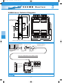
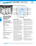
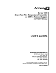
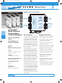
8400100.qxp
3/20/2006
3:18 PM
Page 64
900MB
Modbus/RS-485
Series
RTD/Resistance Input Module
Four
Discrete
Outputs
or
Limit Alarms
Inputs (2)
Four
RTD
or
Resistance
Inputs
Outputs (4)
Isolation
RS-485
Modbus
Inputs (2)
BusWorks® Modbus I/O
10-36V DC
or 24V AC
932/934MB
Multi-Channel
Temperature
Control Modules
RTD or Resistance
Input
Limit Alarms or
Discrete Outputs
Models
932MB: 2 input channels, 2 relay outputs
934MB: 4 input channels, 4 relay outputs
Input
RTD (100 ohm Pt, 120 ohm Ni, 10 ohm Cu),
Resistance (0 to 500 ohms)
Output
Solid-state relays, Form A, SPST-NO
Network Communication
Modbus-RTU high-speed RS-485
Power Requirement
10 to 36V DC,
24V AC
Approvals
CE marked. UL, cUL listed
Class I; Division 2; Groups A, B, C, D.
Power
■ Description
■ Special Features
This signal conditioner is a dual or quad-channel
analog input module with one discrete/relay output per input channel and a Modbus interface. It
filters and linearizes RTD or resistance inputs
while providing isolation between input, output,
power, and network circuits. Lead wire compensation and upscale/downscale sensor break
detection are standard. Low voltage AC and DC
power sources are supported with nonpolarized,
diode-coupled terminals.
■
Standard Modbus RTU protocol with high-speed
RS-485 communication (up to 115K bps)
■
16-bit sigma-delta A/D yields 0.1°C resolution
and 0.25°C accuracy (Pt, Ni RTDs)
■
RTD linearization and sensor break detection
ensure reliable measurements
■
Discrete relay outputs enable local temperature
limit alarms or host-controlled on/off switching
■
Heavy-duty 1A solid-state relays provide
dependable on/off control of industrial devices
■
Self-calibration lowers maintenance costs by
reducing periodic manual calibration checks
■
Watchdog timers provide a configurable
failsafe output state for use when host
I/O communication is lost
■
Four-way isolation eliminates potential ground
loops between power, input, output and
network circuitry
■
Self-diagnostics monitor microcontroller activity
to detect operational failures (lock-up) and
execute a reset to restore communication
The programmable inputs accommodate four
RTD types plus wide-range resistance signals.
Flexible discrete outputs operate as alarms or
on/off controllers. As limit alarms, each discrete
output can be configured with high and/or low
setpoints exclusively tied to an analog input
channel. Alarm trips function without host communication enabling low-cost stand-alone alarms
as well as local backup for the primary control
system. Otherwise, on/off control is based on
commands issued by the host system.
Combining flexible transmitter functions, mixed
signal I/O, alarm support, and a network interface in a single package, makes this instrument
extremely powerful. Multi-channel design adds
cost-efficiency and allows high-density mounting.
Plus, safe, rugged construction makes these
modules reliable for use in both control room
and distributed field I/O applications. Custom
module configurations are also possible (consult
factory for details).
Tel: 248-295-0880 Fax: 248-624-9234 e-mail: [email protected] www.acromag.com
64
8400100.qxp
3/20/2006
3:18 PM
Page 65
Modbus
■ Performance
■
RTD/Resistance Input
Input Ranges
Input type user-configured. Type selected applies to all
channels. RTD linearization, lead wire compensation,
and open circuit or lead break detection are included.
Input Type Alpha Input Range
Accuracy
Pt 100 ohm 1.3850 -200 to 850°C ±0.25°C
Pt 100 ohm 1.3911 -200 to 850°C ±0.25°C
Ni 120 ohm 1.6720 -80 to 320°C
±0.25°C
Cu 10 ohm 1.4272 -200 to 260°C ±1.00°C
Resistance
linear 0 to 500 ohms ±0.05 ohm
Resolution
Alpha
1.3850
1.3911
1.6720
1.4272
linear
Resolution
0.1°C
0.1°C
0.1°C
0.2°C
7.8125 milliohms
Lead-Wire Compensation
Isolation
Inherent for 3-wire RTD. The maximum lead resistance
is 25 ohms per lead (Pt), 20 ohms per lead (Ni), 10
ohms per lead (Cu). All lead wires must be of equal
size and length.
1500V AC for 60 seconds or 250V AC continuous.
4-way isolation between input, network, power and
discrete I/O circuits. Inputs are isolated channel-tochannel for common mode voltage to ±5V DC.
■
■ Ordering
Information
Discrete Output
Output Type
Solid-State Relay (SSR), one Form A (SPST-NO) switch
per input channel. Outputs share a common return
connection at the RTN terminals for low side switching
0 to 48V DC, 1A DC.
932MB-0900
Two channel RTD/Resistance input module
934MB-0900
Four channel RTD/Resistance input module
Output ON Resistance
Accessories
Output Voltage Range
0.4 ohms maximum.
Output Response Time
4.1ms typical, from receipt of command to gate
transition of the output MOSFET.
Operation
Better than ±0.005% of input span per °C, or
±1.0uV/°C, whichever is greater.
Digital outputs are set to their OFF state following a
software or power-on reset. Outputs can be set to
user-defined states following a watchdog timeout.
Noise Rejection
■
Ambient Temperature Effect
Communication
Supported Modbus Commands
Normal mode: 40dB @ 60Hz, typical.
Common mode: 130dB @ 60Hz, typical.
Input Filter Bandwidth
-3dB at 3Hz, typical.
Input Conversion Rate
300ms per channel typical.
RTD Break Detection
Sensor failure can be configured for either upscale or
downscale. Selection applies to all channels.
The command/response protocol for communicating
with this module adheres to the Modbus/RTU standard
for the following Modbus Functions.
Read Holding Registers
Read Coil
Read Input Registers
Reset Slave
Preset Single Register
Report Slave ID
Force Multiple Coils
Force Single Coil
Preset Multiple Register
LED Indicators
LEDs indicate power, status, and discrete level/alarm.
Excitation Current
1mA DC typical, all types.
■
Power and Isolation
Power Requirements
Optional terminal blocks: barrier strip (left) and
spring clamp (right). Cage clamp terminal is standard.
10 to 36V DC (56mA max. at 24V DC).
22 to 26V AC (94mA rms max. at 24V AC).
DIGITAL OUTPUT CONNECTIONS
RTN
OUT0
INL2
IN3+
IN3INL3
COM
PWR
IN2-
B
D
D
A
MECHANICAL
RELAY INTERFACE
INL
JUMP
UP TO
48V DC
NETWORK
COMMUNICATION
TB3
IN-
+
DIGITAL OUTPUT
36 35 34 33 32 31
TB3
LRTN
RS485
IN+
OUT1
IN2+
TB2
TB1/TB2
RTN
OUT2
TB2
934MB Only
2-WIRE RTD
IN1L
RTD INPUTS 2,3
21 22 23 24 25 26
ANALOG
INPUT
IN1-
OUT3
TB4
INL
IN1+
DIG. OUT DIG. OUT
INJUMP
IN0L
932MB/934MB
ANALOG
INPUT
TB1
INL
IN+
IN0-
RTD INPUTS 0,1
IN-
TB1/TB2
DECADE
BOX
11 12 13 14 15 16
RESISTANCE
TB1/TB2
IN+
TB4
TB1
IN0+
46 45 44 43 42 41
ANALOG INPUT
CONNECTIONS
3-WIRE RTD
900C-SIP
Configuration Software Interface Package
(includes software CD-ROM for Windows, RS-232/485
converter, and RS-485/three-wire cable)
4001-095
USB-to-RS232 adapter. See page 70 for more info.
TBK-B02
Optional terminal block kit, barrier strip style, 4 pcs.
TBK-S02
Optional terminal block kit, spring clamp style, 4 pcs.
PS5R-D24
Power supply (24V DC, 2.1A).
See Power Supplies on Page 199.
For more information on software, network hardware,
and mounting accessories, please see Pages 69-71.
AC/DC
POWER
10 TO 36V DC
OR 24V AC
NON-POLARIZED
OUT
RTN
TB4
OUT 3
RTN
RTN
OUT
OUT 2
DIGITAL OUT
SHARES
RETURN
OUT 1
RTN
OUT 0
Tel: 248-295-0880 Fax: 248-624-9234 e-mail: [email protected] www.acromag.com
65
BusWorks® Modbus I/O
Input Type
Pt 100 ohm
Pt 100 ohm
Ni 120 ohm
Cu 10 ohm
Resistance
I/O
8400100.qxp
3/20/2006
3:18 PM
Page 68
900MB
Series
900MB Series Technical Diagrams
TB4
TB3
Acromag
DFT
B
A
D
D
TB3
TB1
2.34
(59.4)
BusWorks® Modbus I/O
PWR
TB2
2 3
CL
RS485
3.75
(95.3)
0 1
36 35 34 33 32 31
TB4
ST
COM
COM
46 45 44 43 42 41
RUN
4.68
(118.9)
"T" Rail Din Mounting
Din EN 50022, 35mm
11 12 13 14 15 16
21 22 23 24 25 26
TB2
TB1
3.90
(99.1)
1.05
(26.7)
NOTE: ALL DIMENSION ARE IN INCHES (MILLIMETERS)
4.35
(110.5)
PERSONAL COMPUTER
W/ WINDOWS 95/98 OR NT
RS-232 SERIAL
PORT CONNECTOR
AT BACK OF PC
PC RUNNING
ACROMAG
MODBUS CONFIG
SOFTWARE
INSTALL MODBUS
CONFIGURATION
SOFTWARE
RS-232 TO RS-485 CONVERTER
MODEL 5034-214
CONNECT THE RS-232
SIDE OF CONVERTER
TO THE PC
CAUTION: DO NOT CONNECT THE
CABLE DIRECTLY TO THE PC WITHOUT
THE CONVERTER, OR DAMAGE TO
THE MODULE MAY RESULT.
CABLE 5034-202
CONNECT THE RS-485
SIDE OF CONVERTER
TO THE CABLE
900C-SIP COMMUNICATION CONNECTIONS
CB
A
CONNECT WIRES AS SHOWN
COM D
TB4
TB4
Acromag
RUN
RED
RS-485
D
B
BLACK
D
C
GREEN
COM
REFER TO THE USER'S MANUAL
THAT CAME WITH YOUR MODULE
TO COMPLETE THE MODULE'S
POWER AND I/O CONNECTIONS
TB2
TB1
COLOR
A
PWR
ANY 900MB MODULE
TB1
R
A
STATUS LED FLASHES IN
DEFAULT MODE.
B
RS485
D
DEFAULT MODE SWITCH PUSH FOR DEFAULT MODE.
D
TB3
3
WIRE
36 35 34 33 32 31
COM
2
46 45 44 43 42 41
TB3
COM
1
RUN/PWR LED (GREEN)
STATUS LED (YELLOW)
TB4
ST
DFT
0
D
11 12 13 14 15 16
21 22 23 24 25 26
TB1
TB2
Tel: 248-295-0880 Fax: 248-624-9234 e-mail: [email protected] www.acromag.com
68
3/20/2006
3:18 PM
Page 69
Modbus
Configuration Kit
Software Interface Package
Model No. 900C-SIP
RS-485 Cable
(DB-9)
RS-232 to RS-485
Converter
(non-isolated)
Configuration Software
for Windows
■ Ordering Information
Software
Interface Package
900C-SIP
Software Interface Package.
Includes Configuration Software (5034-186),
Non-isolated RS-232 to RS-485 Serial Port Converter
(5034-214), and RS-485 Cable (5034-202).
Items can also be ordered separately below.
5034-186
Configuration Software for Windows (95/98/2000/ME/
NT4/XP) on CD-ROM.
5034-214
Non-isolated RS-232 to RS-485 Serial Port Converter,
DB-9F to DB-9F.
5034-202
RS-485 to 3-wire Cable Converter,
DB-9M to 3 x 12AWG RS-485 Cable, 8 ft.
This package includes Windows® Configuration
Software, an RS-232-to-485 Serial Port
Converter, and an RS-485 Signal Cable. These
components provide everything you need to set
up a Series 900 I/O module from your desktop
PC before installing it on the network.
RS-232/485
Converter
(non-isolated)
RS-485
to 3-wire
5034-214
5034-202
■ Ordering Information
Universal 50W
Power Supply
Top View
(dimensions in mm)
Side View
(dimensions in mm)
5
6.
-ø
10
3.8
90
80
ø4
4-
13
.5
The PS5R-D24 is the
ideal power source
to drive your
network.
PS5R-D24
Universal Power Supply
13
13
13
DC ON
35.3
Universal power
85 to 264V AC,
105 to 370V DC
60
75
Input Power
Requirement
V.ADJ
Output
5
24V DC, 2.1A (50W)
M3.5
Terminal Screws
6
95
12
Mounting Hardware
DIN-Rail
Mounting
For your convenience, Acromag offers several
mounting accessories to simplify your system
installation. Our 19” rack-mount kit provides a
clean solution for mounting your I/O modules
and a power supply. Or you can buy precut DIN
rail strips for mounting on any flat surface.
■ Ordering Information
20RM-16-DIN
19" rack-mount kit with DIN rail.
DIN RAIL 3.0
DIN RAIL 16.7
DIN rail strip, Type T, 3 inches (75mm) or
16.7 inches (425mm)
Dimensions in inches (mm).
Tel: 248-295-0880 Fax: 248-624-9234 e-mail: [email protected] www.acromag.com
69
BusWorks® Modbus I/O
Network Power
I/O
7.35
8400100.qxp
Accessories
Model 4001-095 USB-to-Serial Adapter
HOST
USB
PERSONAL COMPUTER
RUNNING WINDOWS
98/ME/2000/XP
TO HOST USB PORT
4001095
USB SERIAL CONVERTER
USB MALE
HOST PC RUNNING
ACROMAG
CONFIGURATION
SOFTWARE
LED
RS232
DB9P
6 FEET OF CABLE
Simplifies configuration of Acromag I/O Modules ◆ Enables configuration via USB port
Description
Performance Specifications
Ordering Information
This device is a USB-to-serial adapter that you
can use to communicate with many Acromag I/O
products for setup and re-configuration for your
application.
USB Specification
Version 1.1
Data rate
Up to 115.2Kbps
Environmental Standards
RoHS-compliant
Basic Power Consumption
150mA
PC Requirements
Windows® 7 (32-/64-bit) / Vista (32-/64-bit) /
XP (32-/64-bit) / Server 2003 & 2008 (32-/64-bit) /
2000 / ME / 98SE / 98
NOTE: For more information visit www.acromag.com.
Key Features & Benefits
■
Connects to I/O modules via USB
(other adapters may be necessary)
■
Complete RS232 control signals
■
Conforms to USB Specification, Version 1.1
■
USB-powered
■
Cable length, 6 ft., UL approved
IntelliPack 800x Series
Adapter and Cable
INTELLIPACK
SERIAL ADAPTER
Adapters
4001-095
USB to serial adapter. Includes driver CD and manual.
5030-913
Serial port adapter. DB9S connector to RJ11 jack.
5034-202
RS-485 to 3-wire cable converter and cable, DB-9M to
3 x 12AWG RS-485 cable, 8 ft.
5032-287
RS-232 to 151T transmitter configuration device
converter and cable, 6 ft.
5034-214
Non-isolated RS-232 to RS-485 Serial Port Converter,
DB-9F to DB-9F.
Cables
RJ11 JACK
(6 CONDUCTOR)
5030-902
Cable. 6 feet long with RJ11 plug at each end.
RJ11 PLUG
(6 CONDUCTOR)
MODEL 5030-902
(6 feet long)
9-PIN CONNECTOR (DB9S)
MODEL 5030-913
4
4
3
mV+
3 & 4 Wire RTD
2
1
-T/C,
2 3
1
–
MODEL 5032-787
CABLE 5034-202
TOP VIEW
RS-485
RS-232
5034-202
C
DB9 FEMALE
6 FEET OF CABLE
151T TRANSMITTER
+
1046-016
Acromag
1046-016
Acromag
RS232 TO RS485 SERIAL
CONVERTER
(MODEL 5034-214)
TO RS232
TOP VIEW
900MB Modbus Series
Adapter and Cable
PLUG INTO TOP
OF TRANSMITTER
151C-SIP
INTERFACE ADAPTER
Transmitter
temperature
of 151T
plug into top
151T Transmitter Series
Adapter and Cable
DB9 FEMALE
B
A
DB9 MALE
COM D D
Tel: 248-295-0880
Bulletin #8400-572
■
Fax: 248-624-9234
■
[email protected]
■
www.acromag.com
■
30765 S Wixom Rd, Wixom, MI 48393 USA
All trademarks are property of their respective owners. Copyright © Acromag, Inc. 2009. Data subject to change without notice. Printed in USA 10/2009.