1
d o c u m e n t a t i o n
T e c h n i c a l
t
INSTALLATION AND USER GUIDE FOR
GASSONIC OBSERVER
ULTRASONIC GAS LEAK DETECTOR
INSTALLATION AND USER GUIDE FOR
GASSONIC OBSERVER
ULTRASONIC GAS LEAK DETECTOR
From serial number: 1011-014
Installation and User Guide for Gassonic Observer (BB 6017-09)
Table of contents
Page:
1. Technical Data On The Gassonic Observer......................................................................................................................................3
2. Introduction.....................................................................................................................................................................................4
3. General Description and Features...................................................................................................................................................4
3.1. Area monitored by the Gassonic Observer:..................................................................................................................4
3.2. Detector Outputs.........................................................................................................................................................4
4. Installation.......................................................................................................................................................................................5
4.1. Mechanical construction..............................................................................................................................................5
4.2. Mechanical operation and safety.................................................................................................................................6
4.3. Mounting......................................................................................................................................................................6
4.4. Replacement parts.......................................................................................................................................................6
4.5. Wiring diagram.............................................................................................................................................................7
5. Operation and Setup........................................................................................................................................................................8
5. Operation and Setup....................................................................................................................................................8
5.1. Normal operation.........................................................................................................................................................8
5.2. Acoustic Self-test.........................................................................................................................................................8
5.3. Output Methods...........................................................................................................................................................8
5.3.1. Alarm relay output.............................................................................................................................................8
5.3.2. 4-20 mA output.................................................................................................................................................9
5.3.3. Error output.......................................................................................................................................................9
5.3.4. RS485 Digital Communication........................................................................................................................10
5.4. User Interface Settings..............................................................................................................................................11
5.4.1. Forced Acoustic Test........................................................................................................................................11
5.4.2. Setting/Checking Trigger Level........................................................................................................................11
5.4.3. Setting/Checking Delay Time..........................................................................................................................12
5.4.4. Setting/Checking Alarm Relay Energized/De-energized..................................................................................12
5.4.5. Setting/Checking Alarm latching ON/OFF.......................................................................................................13
5.4.6. Setting/Checking RS485 Address...................................................................................................................13
5.4.7. Setting/Checking Factory Default ON/OFF......................................................................................................14
6. Gain Test and Calibration..............................................................................................................................................................15
6.1. Gain Test....................................................................................................................................................................15
6.2. Calibration.................................................................................................................................................................15
7. RS485 Digital Interface.................................................................................................................................................................16
7.1. Customer Commands.................................................................................................................................................16
7.2. Detailed “Customer Command” description...............................................................................................................17
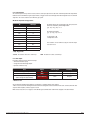
1. Technical data on the Gassonic Observer
ACOUSTIC SPECIFICATIONS
Microphone unit:
Detector frequency range: 25 kHz – 70 kHz
Dynamic range: 58 dB – 104 dB
GAS LEAK DETECTION COVERAGE (REF= METHANE)
Ultrasonic background noise < 74 dB, (low noise areas)
12 m radius @ leak rate = 0.1 kg/sec
8 m radius @ leak rate = 0.03 kg/sec
TEST SOUND SOURCE:
Test frequency: 40 kHz +/- 3 kHz
Sound pressure: 100dB, 60 mm from the sound source
Ultrasonic background noise < 84 dB, (high noise areas)
8 m radius @ leak rate = 0.1 kg/sec
4 m radius @ leak rate = 0.03 kg/sec
POWER REQUIREMENTS
Input voltage: 15 – 30 VDC (Class 2 power supply for UL/ULc areas)
Maximum current consumption: 250 mA
Certifications
ATEX: Ex II 2G EEx d e ib IIB + H2 T6
UL/ULc: Flameproof enclosure. CLASS 1 DIV 1 Groups BCD
–40°C to +60°C
IECEx: Ex II 2G EEx d e ib IIB+H2 T6
GGTN K Permit to use, Kasakhstan
GOST R (Russia): Pending
OUTPUT SIGNALS
• Analogue 4 - 20 mA interface
(Maximum permitted load resistance is 500Ω):
0 mA: No power / Low supply voltage
1 mA: Acoustic error
3 mA: Unit inhibit
4 – 20 mA: 58 dB – 104 dB SPL
• Digital RS 485 interface
• Relay1 - Error/fault indication (NC):
Load: 500 mA max. Switch Voltage: 200 VDC max.
• Relay2 - Indication of alarm trigger level reached.
Load: 500 mA max. Switch voltage: 200 VDC max.
Factory default = NC (de-energized).
This can be changed by the operator.
ENVIRONMENTAL DATA
Operational temperature range: -40°C to 60°C
Humidity: 0 to 100% relative humidity
INGRESS PROTECTION
EN60529/A1: IP66
RF EMISSION AND IMMUNITY
Tested according to:
EN61010-1
EN61000-6-2
EN61000-6-3
CONSTRUCTION
Stainless steel AISI 316L
Weight: 7.5 Kg
DIMENSIONS
Ø 202*189 mm (7.95 * 7.44 in)
2. Introduction
The Gassonic Observer is an ultrasonic gas leak detector for detecting pressurised gas leaks.
This user manual describes how to install the Gassonic Observer and how to make the necessary checks and adjustments to ensure
optimal performance.
3. General Description and Features
The Gassonic Observer detects leaks from pressurised gas systems by sensing the airborne ultrasound produced by the gas escaping.
This detection method is omnidirectional. It can function in extreme weather conditions and is ideal for monitoring leaks from valves
and flanges in complex pipeline systems, both onshore and offshore.
The detector has the following certifications:
ATEX approval, Ex II 2G EEx d e ib IIB+H2 T6 according to standards EN 50014, EN 50018, EN 50019 and EN 50020 (certificate
number DEMKO 04ATEX136396). UL/ULc approval, Class 1 Div 1 Group BCD –40°C to +60°C, according to standards UL 1203 and UL
913. IECEx approval, Ex II 2G Ex d e ib IIB+H2 T6 according to standards IEC 60079-0, IEC 60079-1, IEC 60079-7 and IEC 60079-11
(certificate number ULD 05.0007). A copy of the ATEX certificate is available on request from your local Gassonic representative.
The detector housing is casted AISI 316L, acid-proof stainless steel and the ingress protection is IP66.
The performance of the Gassonic Observer as a safety device is not covered by the ATEX certificate.
Installation and User Guide for Gassonic Observer (BB 6017-09)
Page 3
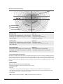
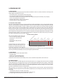
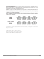
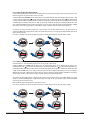
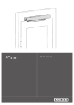
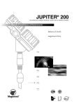
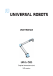
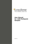
Detection Coverage Characteristics
High-noise areas
LOW-noise areas
VERY LOW-noise areas
High-noise areas
In ”high-noise areas” (background noise < 78dB), the trigger
level must be set at 84 dB. This corresponds to a detection
radius of 5-8 metres.
Typical areas:
• Turbo compressor areas
• Complete open offshore weather deck
• Next to very noisy machinery
Low-noise areas
In ”low-noise areas” (background noise < 68dB), the trigger
level must be set at 74 dB. This corresponds to a detection
radius of 9-12 metres.
Typical areas:
• Areas with no machinery
• Areas with low frequency machine made noise
Very Low-noise areas
In ”very low-noise areas” (background noise < 58dB), the trigger
level must be set at 64 dB. This corresponds to a detection
radius of 13-20 metres.
Typical areas:
• Onshore wellhead areas in calm environment
• Salt dome gas storage facilities in calm environment
3.1. Area monitored by the Gassonic Observer
The detection coverage of the Gassonic Observer is determined by the ultrasonic noise levels in the area of installation. Experience
has shown that most process environments can be divided into three overall noise levels. This is illustrated in the image below. The
detection coverage characteristics are based on live tests and show the minimum coverage of the Gassonic Observer detector in areas
without solid physical obstructions between the detector and the leak. For further instructions on installation, Gassonic A/S can be
consulted.
3.2. Detector Outputs
The Gassonic Observer detector has several output methods:
• Analogue 4–20 mA interface - Sink or Source (Factory setting = Source)*
• Digital RS485 interface
• Alarm relay
The Alarm relay is controlled by an adjustable trigger level in 5 dB steps, from 59 to 99 dB and has an adjustable internal
alarm delay from 0 to 600 seconds. It is necessary to introduce an alarm delay of at least 10 seconds either internally or in the
control system. (Factory setting - 79 dB and 10 seconds delay)
• Error relay (NC)
* Sink - The detector receives a current loop. Source - The detector sends out a current loop.
Installation and User Guide for Gassonic Observer Ultrasonic gas leak detector
Page 4
4. Installation
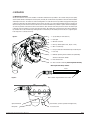
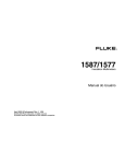
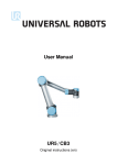
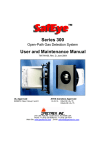
4.1. Mechanical construction
The Gassonic Observer consists of two chambers. In the ATEX certification the top chamber is an increased safety enclosure (EExe)
and the bottom chamber is a flameproof enclosure (EExd). In the UL/ULc certification the top chamber as well as the bottom chamber
are flameproof enclosures. The cables are connected through M20 x 1.5 cable entries in the top chamber using approved EExe glands
or approved conduit with seal installed within 18” of the detector. The inner cores of the cable penetrating the detector should be at
least 25 cm long. This will ensure no tension on the wires and connector PCB when the top chamber is opened. The two mounting bolts
are on the top chamber of the detector and this means that the cables will enter on the fixed part of the detector. The bottom part
is attached to the top by means of six allen screws with lock washers. Unscrewing these screws will expose the connector PCB in the
top chamber. These screws will be fixed by retaining washers to the bottom part. The bottom part of the detector is supported by the
Load-strap, which is connected to the top.
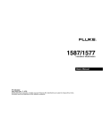
Figure 1.
1. Top (the fixed part of the detector)
2. Flame path
3. M5 Earth Connection
4. Inner top chamber (ATEX – EExe, UL/ULc – EExd)
5. M20 x 1.5 cable entry
6. Factory installed earth wire between top and bottom parts
7. Load-strap
8. Bulkhead separating the two chambers and permanently
attached to the bottom chamber.
9. EExe Connector PCB
10. Allen screw and lock washer (must be tightened with 9 Nm)
Wire lengths inside the top chamber
25 cm
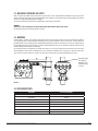
Figure 2.
Wire insulation stripped between 8 and 10 mm.
Optical link window
User Interface (Switches operated with magnet-stick)
Microphone
Test sound source
Installation and User Guide for Gassonic Observer (BB 6017-09)
Page 5
4.2. Mechanical operation and safety
When closing the top chamber ensure that the Load-strap and wires are not caught between the bulkhead and the top part of the
detector. Check the status of the O-ring and the flame path (if top chamber is used as EExd). Replace O-ring if damaged. Send unit to
Gassonic for repair if the EExd flame path is damaged.
The six allen screws with lock washers must be tightened to 9 Nm using a torque-wrench.
WARNING:
The inner six screws should not be unscrewed and the bottom EExd chamber should not be opened.
The warranty will be void if the bottom chamber is opened.
4.3. Mounting
Two M8 stainless steel bolts (not supplied), 88mm apart, attached to the top of the detector are used to fix the Gassonic Observer
in its operating position. These bolts may penetrate the detector top by a maximum of 14 mm. The detector can be mounted to a
freestanding pole or wall, using the Gassonic mounting bracket UA1352. This bracket is an optional accessory and is supplied with two
M8 mounting U-bolts which can fit around a pole with a maximum dimension of 63 mm. It is possible to mount the detector directly
onto non-vibrating structural beams or cable-trays.
The microphone should face downwards and if tilting of the detector is necessary, the angle of incline should not exceed 45°. Avoid
when mounting the detector within a half metre from a solid structure for example a wall or a big vessel, to point the acoustic test
sound source into the direction of this structure. The sound source should as far as possible be pointing into free space.
M8 mounting bolt.
(not supplied).
Maximum screw
depth into the top
is 14 mm.
Figure 3.
4.4. Replacement parts
Description
Gassonic Part Number
Allen screw
YQ9850
Lock washer
YO0684
O-ring
YJ0908
Microphone
MM4190
Sound source assembly
UD0131
Magnet-stick
UC5352
Torque-wrench
EZ1000
Mounting Bracket
UA1352A
Installation and User Guide for Gassonic Observer Ultrasonic gas leak detector
Page 6
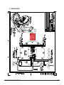
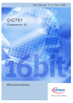
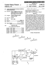
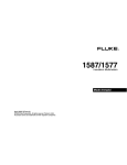
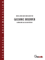
Warning:
Do not connect
supply wires to
the 4-20 mA input
4.5. Wiring diagram
Installation and User Guide for Gassonic Observer (BB 6017-09)
Page 7
5. Operation and Setup
5.1. Normal operation
On power up of the Gassonic Observer the unit will perform an initialization of the micro-controller, internal tests and then goes into
normal operation mode within a few seconds.
• The real-time ultrasonic sound level will be shown on the display. • The corresponding 4-20 mA value will be set on the analogue output.
• The Alarm relay is Normally open (de-energized) but this can be changed by the operator to Normally closed (energized).
• The error relay is Normally closed (energized).
• The RS485 digital interface is ready to receive command.
• The acoustic Self-test is done at regular intervals.
in .
15
m
ec
o
Te nds*
st
f ai
l
8s
ec
o
Te nds*
st
fa
3 0 il
se
c
Te onds
st
8s
15
m
in
Te . (si
nc
st
el
as
8s
t te
ec
st)
on
d
Te
s t s*
fa
3 0 il
se
c
Te onds
st
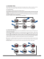
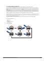
5.2. Senssonic™ acoustic self-test
An acoustic self-test (named Senssonic™) is done every 15 minutes and takes approximately 8 seconds. A test signal with a frequency
sweep at a constant amplitude is transmitted by the ultrasonic sound source to the microphone. The detector analyses the result of the
sweep and stores the highest dB value. This value is compared to a factory reference value and the result must be within a predefined
tolerance. If the test signal is out of the predefined tolerance, the Observer will do a new acoustic self-test 30 seconds after the first
failed test. If this test signal is still out of tolerance a new acoustic self-test is done again 30 seconds later. If the third test signal is
still out of tolerance, the Gassonic Observer will go into acoustic error mode. In acoustic error mode the code “ERAC” will be displayed,
the Error Relay will be de-energized and the user can acquire the relay status via the RS485 digital interface. Furthermore, the 4-20
mA output will indicate 1 mA for 5 seconds and return to normal ultrasonic background noise level until the next acoustic test failure.
This sequence will repeat until the acoustic fault is repaired.
Acoustic self-test sequence
There could be a number of causes for this error:
• There is an obstacle blocking the sound path.
• The sound source is faulty and needs
replacement.
• The microphone is faulty and needs
4 mA
replacement.
If none of the above is true, the unit can be tested
1 mA
by means of a ”Gain Test” with a Gassonic 1701
5 seconds
Portable Test and Calibration Unit, before sending
* Acoustic self-test duration is approximately 8 seconds
the unit back to Gassonic for service. When the
detector is performing the Acoustic Self-test the last dB level is displayed on the user interface and sent to the 4-20 mA output. During
this time a green LED will be illuminated and can be seen through the optical link window.
5.3. Output Methods
The Gassonic Observer has three major output methods:
• Alarm Relay output.
• Standard source 4-20 mA analogue output.
• RS485 digital communication (Half duplex).
In addition to this the detector has an Error Relay. The users need to determine the output method suited for their use.
5.3.1. Alarm relay output
When using this method, an internal trigger level and delay time must be set. The trigger level should be at least 6 dB higher
than the background noise. The trigger level can be set in steps of 5 dB from 59 dB to 99 dB and the factory setting is 79 dB. An alarm
delay time is implemented to eliminate spurious alarms due to short background noise peaks. This delay time can be set internally
from 0 to 600 seconds through the user interface or via the RS485 digital interface. The factory setting is set to 01 (10 seconds).
The delay can alternatively be set in the ”Fire and Gas Panel”.
When a gas leak occurs in the detector’s coverage area, the trigger level will be reached, the LED in optical link window will be
illuminated and the alarm relay timer will be started. When the delay times out, the unit will go into alarm mode, which will result in
the following:
• The dB value preceded by an “A” will flash on the display.
• The alarm relay will energize (if in factory default) and the contact will close.
For setting of trigger level and delay time see section 5.4.2. and 5.4.3
Installation and User Guide for Gassonic Observer Ultrasonic gas leak detector
Page 8
5.3.2. 4-20 mA output
The 4-20 mA output is factory set to be Source1, but this can be specially ordered to be Sink2. At normal operation the output will be
between 4 and 20 mA. When using this output method, a trigger level at least 6 dB higher than the background noise and an alarm
delay time > 10 seconds should be set in the fire & gas system.
dB and mA comparison for trigger levels:
dB
The output value in mA corresponding to the sound pressure in
dB can be calculated by the following formula:
{[(n – 58) * 16] / 46} + 4 = x
mA Output
≤ 58
4.0
59*
4.3
64*
6.1
69*
7.8
74*
9.6
79*
11.3
84*
13.0
89*
14.8
94*
16.5
99*
18.3
≥ 104
20.0
The transposed formula:
{[(x – 4) * 46] / 16} + 58 = n
n: Sound Level in dB
x: Output value in mA
Error readouts can be monitored using the 4-20 mA output.
See section 5.3.3.
* Relay trigger levels
1 Source - The detector sends out a current loop. 2 Sink - The detector receives a current loop.
5.3.3. Error output
Error/fault conditions are indicated in three ways:
• On the User Interface display.
• Through the 4-20 mA analogue output.
• By means of the Error relay.
Error
Display
4-20 mA output
Error Relay
Low Supply Voltage
ERV-
0 mA *
De-energized
Acoustical Error
ERAC
1 mA *
De-energized
Unit Inhibit (communicating with the
detector through the User Interface)
(See section 5.4)
3 mA *
Energized
* Tolerance: ± 0.4
The unit will have an Inhibit output when the local operator is changing settings on the detector.
1 mA for 5 seconds and then showing the measured ultrasonic background noise level until the next acoustic self-test, where the same
sequence will be repeated, if the test signal is too low.
When a forced acoustic test is in progress via the RS485 digital communication “COM” will be displayed on the User Interface.
Installation and User Guide for Gassonic Observer (BB 6017-09)
Page 9
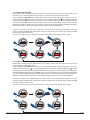
5.3.4. RS485 Digital Communication
Via the ”half duplex” RS485 interface the user can look up and change various settings of the Gassonic Observer. Up to 32 Gassonic
Observer units can be connected into a RS485 multidrop interface. The transmission line should be terminated at both ends (at
master computer and before last unit) of the line with a 120 Ohm resistor.
The Gassonic Observers can not initiate a communication, but can only respond to a command from the master computer. The
Gassonic Observers operate in polled slave mode. When the master computer broadcasts an address, a command, a variable and
checksum, the Gassonic Observer with that address will respond. The Gassonic Observer will respond with its identification (address),
a response, a variable and a checksum. The use of a checksum ensures that if data corruption occurs during transition, the information
is disregarded and the information is transmitted again.
The units should be connected by means of a ”twisted pair” cable to reduce the effect of interference. A low Baud rate of 2400 Baud
is used for the RS485 communication.
MASTER
COMMAND
GASSONIC OBSERVER
RESPONSE
ADDRESS
COMMAND
VARIABLE
CHECKSUM
SDDDDDDDDS
B 012 3 4 5 67B
SDDDDDDDDS
B 012 3 4 5 67B
SDDDDDDDDS
B 012 3 4 5 67B
SDDDDDDDDS
B 012 3 4 5 67B
IDENTIFIER
RESPONSE
VARIABLE
CHECKSUM
SDDDDDDDDS
B 012 3 4 5 67B
SDDDDDDDDS
B 012 3 4 5 67B
SDDDDDDDDS
B 012 3 4 5 67B
SDDDDDDDDS
B 012 3 4 5 67B
To allow the Gassonic Observer to distinguish between the address field and other fields, D7 is always set in the address field and
always cleared in other fields.
Computer Checksum = (ADDD0-D6 ) + (CMDD0-D6 ) + (VARD0-D6 )
Gassonic Observer Checksum = (IDD0-D6 ) + (RESD0-D6 ) + (VARD0-D6 )
A detailed description of the protocol can be found in section 7.
Installation and User Guide for Gassonic Observer Ultrasonic gas leak detector
Page 10
5.4. uSeR inTeRFace SeTTinGS
The User Interface consists of a four-digit LED display window and four magnetic switches to enable a local operator to confirm or
change settings without opening the unit. When the user interface is used the unit will move out of normal operating mode.
5.4.1. Forced Acoustic Test
This will enable the local operator to test the acoustic properties of the unit.
Activate the MENU switch with the magnet-stick. The code “ATOF” (Acoustic Test Off) will be displayed. Activating the UP switch ( )
will display the “wait” command followed by the sound level detected by the microphone emitted from the sound source. If this value
is flashing, the unit is failing the acoustic test. There could be a number of causes for this error, see section 5.2. for more information.
The DOWN switch ( ) will stop the acoustic test and display “ATOF”. Activating the ENTER switch at any time during this operation will
display “DONE” and take the unit back to Normal Operation.
If no switch is activated for 60 seconds the detector will return to normal operation.
ATOF
wait
099
099
DONE
> 58
5.4.2. Setting/Checking Trigger Level
The trigger level can be set from 59 to 99 dB in steps of 5 dB. The ALARM RELAY will activate at this trigger level changing from open
contact to closed (factory default).
Activate the MENU switch twice with the magnet-stick. The current trigger level will be displayed (factory setting = 79 dB). Activating
the UP switch ( ) will increment the trigger level by 5 dB. Activating the DOWN switch ( ) will decrement the Trigger Level in 5 dB
increments. Activating the ENTER switch without changes made, switches the unit back to Normal Operation. Activating the ENTER
switch with changes made, will flash “SAVE” on the display. Confirm the save action by activating the ENTER switch once more.
Activating the MENU switch while “SAVE” is flashing, will discard the save and switch the unit back to Normal Operation. If ENTER was
activated the unit will display “DONE” to confirm that the changes have been saved and return to Normal Operation.
NB. The operator can change the trigger level and if desired move to the next item (delay time) in the menu structure by activating
the MENU switch straight after the change. The change will be saved at a later stage by activating the ENTER switch at any point in
the menu structure.
If no switch is activated for 60 seconds the detector will return to normal operation without saving the changed settings.
TL79
TL74
SAVE
DONE
DT01
> 58
X2
Installation and User Guide for Gassonic Observer (BB 6017-09)
Page 11
5.4.3. Setting/Checking Delay Time
The delay time is linked to the ALARM RELAY. The delay time can be set from 0 to 600 seconds. If the relay output is being used for
executive action, it is of utmost importance that the delay time is of a sufficient length to eliminate spurious alarms.
Activate the MENU switch three times with the magnet-stick. The current delay time will be displayed (factory setting = 01 = 10 sec.).
Activating the UP switch ( ) will increment the delay time by 10 sec. Activating the DOWN switch ( ) will decrement the delay time
by 10 sec. Activating the ENTER switch without changes made, switches the unit back to Normal Operation. Activating the ENTER switch
with changes made, will flash “SAVE” on the display. Confirm the save action by activating the ENTER switch once more. Activating the
MENU switch while “SAVE” is flashing, will discard the save and switch the unit back to Normal Operation. If ENTER was activated the
unit will display “DONE” to confirm that the changes have been saved and return to Normal Operation.
The operator can change the delay time and if desired move to the next item (alarm relay energized/de-energized) in the menu
structure by activating the MENU switch straight after the change. The change will be saved at a later stage by activating the ENTER
switch at any point in the menu structure.
If no switch is activated for 60 seconds the detector will return to normal operation without saving the changed settings.
DT01
DT00
SAVE
DONE
RL E
> 58
X3
5.4.4. Setting/Checking Alarm Relay Energized/De-energized
The Alarm Relay is normally de-energized at power up of the unit. The output is an open contact. The output can be changed to closed
contact at alarm by energizing the Alarm Relay.
Activate the MENU switch four times with the magnet-stick. The current Alarm Relay status will be displayed (factory setting = RL E =
energized). Activating the UP switch ( ) will switch the Alarm Relay status to de-energized. Activating the DOWN switch ( ) will switch
the Alarm Relay status back to energized. Activating the ENTER switch without changes made, switches the unit back to Normal Operation.
Activating the ENTER switch with changes made, will flash “SAVE” on the display. Confirm the save action by activating the ENTER switch
once more. Activating the MENU switch while “SAVE” is flashing will discard the save and switch the unit back to Normal Operation. If
ENTER was activated the unit will display “DONE” to confirm that the changes have been saved and return to Normal Operation.
The operator can change the relay energizing settings and if desired move to the next item (alarm latching ON/OFF ) in the menu
structure by activating the MENU switch straight after the change. The change will be saved at a later stage by activating the ENTER
switch at any point in the menu structure.
If no switch is activated for 60 seconds the detector will return to normal operation without saving the changed settings.
RLE
RLDE
SAVE
DONE
ALOF
> 58
X4
Installation and User Guide for Gassonic Observer Ultrasonic gas leak detector
Page 12
5.4.5. Setting/Checking Alarm latching ON/OFF
The alarm latching feature gives the local operator the opportunity to latch the alarm relay output in alarm even if the sound level drops
below the trigger level. The alarm latching is factory set to OFF.
Activate the MENU switch five times with the magnet-stick. The current Alarm Latching status will be displayed (factory setting = ALOF
= OFF). Activating the DOWN switch ( ) will switch the Alarm Latching status to ON. Activating the UP switch ( ) will switch the Alarm
Latching status back to OFF. Activating the ENTER switch without changes made, switches the unit back to Normal Operation. Activating
the ENTER switch with changes made, will flash “SAVE” on the display. Confirm the save action by activating the ENTER switch once
more. Activating the MENU switch while “SAVE” is flashing will discard the save and switch the unit back to Normal Operation. If ENTER
was activated the unit will display “DONE” to confirm that the changes have been saved and return to Normal Operation.
The operator can change the latching settings and if desired move to the next item (RS485 Address) in the menu structure by
activating the MENU switch straight after the change. The change will be saved at a later stage by activating the ENTER switch at any
point in the menu structure.
If no switch is activated for 60 seconds the detector will return to normal operation without saving the changed settings.
ALOF
ALON
SAVE
DONE
AD00
> 58
X5
5.4.6. Setting/Checking RS485 Address
The RS485 Address is a two-digit number from 00 to 99. This can only be changed locally.
Activate the MENU switch six times with the magnet-stick. The current RS485 Address will be displayed (factory setting = 00).
Activating the UP switch ( ) will increment the RS485 Address. Activating the DOWN switch ( ) will decrement the RS485 Address.
Activating the ENTER switch without changes made, switches the unit back to Normal Operation. Activating the ENTER switch with
changes made, will flash “SAVE” on the display. Confirm the save action by activating the ENTER switch once more. Activating the
MENU switch while “SAVE” is flashing will discard the save and switch the unit back to Normal Operation. If ENTER was activated the
unit will display “DONE” to confirm that the changes have been saved and return to Normal Operation.
The operator can change RS485 address settings time and if desired move to the next item (Factory Default ON/OFF) in the menu
structure by activating the MENU switch straight after the change. The change will be saved at a later stage by activating the ENTER
switch at any point in the menu structure.
More information about the RS485 protocol is available in section 7.
If no switch is activated for 60 seconds the detector will return to normal operation without saving the changed settings.
AD00
AD01
SAVE
DONE
FDOF
> 58
X6
Installation and User Guide for Gassonic Observer (BB 6017-09)
Page 13
5.4.7. Setting/Checking Factory Default ON/OFF
The Factory Default command gives the local operator the opportunity to return all settings to factory default.
Activate the MENU switch seven times with the magnet-stick. Factory Default OFF (FDOF) will be displayed. Activating the DOWN switch
( ) will switch the Factory Default ON. Activating the UP switch ( ) will switch the Factory Default OFF. Activating the ENTER switch
without changing the status to ON, switches the unit back to Normal Operation. Activating the ENTER switch having changed the status
to ON, will flash “SAVE” on the display. Confirm the save action by activating the ENTER switch once more. Activating the MENU switch
while “SAVE” is flashing will discard the save and switch the unit back to Normal Operation. If ENTER was activated the unit will display
“DONE” to confirm that all settings have been returned to the Factory Default and return to Normal Operation.
Activating the MENU switch an eighth time will switch the unit to Normal Operation, if any changes were made in previous menu items
(not in factory Default ON/OFF) the unit will flash “SAVE” on the display. Confirm the save by activating the ENTER switch or discard
the save by activating the MENU switch once more.
If no switch is activated for 60 seconds the detector will return to normal operation without saving the changed settings.
The Factory default settings are:
•
•
•
•
•
Triggerlevel79
Delaytime01
Alarmrelayde-energized
Alarmlatchingoff
RS485addressto00
FDOF
FDON
SAVE
DONE
>54
> 58
X7
Installation and User Guide for Gassonic Observer Ultrasonic gas leak detector
Page 14
6. Gain TeST and caliBRaTion
Calibration of the Gassonic Observer is only needed when the unit is more than ±3 dB out of tolerance. This can be verified by doing
an Observer Gain Test on the unit. The Observer Gain Test is one of the test sequences of the Gassonic 1701.
Calibration is done with a calibrated Gassonic 1701.
6.1. Gain Test
Set the Gassonic 1701 into Observer Gain Test (See Gassonic 1701 User Manual for details).
Turn the Gassonic 1701 onto the Gassonic Observer and activate the Gain Test by pressing ENTER or TEST button.
The Gassonic 1701 will output a constant sound pressure level of 99dB for 8 seconds and then to 0dB for 3 seconds. Thereafter, the
sound pressure level will return to 99dB and the sequence will be repeated until a new sound pressure level is selected or the test
stopped.
To select a new sound pressure level the DOWN button should be pressed. There are four levels; 99dB, 89dB, 79dB and 64dB.
The dB readout on the display of the Gassonic 1701 can now be compared with that of the Observer.
6.2. Calibration
Set the Gassonic 1701 into Observer Gain Test (See Gassonic 1701 User Manual for details).
Set the Gassonic Observer into Calibration mode by holding the magnet stick on the ENTER switch for more than 3 seconds. The
Observer will display a flashing ”CAL”. Verify the need for calibration by activating the ENTER switch one more time. The Observer will
now display a flashing ”1701”. This indicates that the Gassonic Observer is ready for calibration and is awaiting communication from
a Gassonic 1701 unit.
Hold for more than 3 seconds
> 45
CAL
1701
Turn the Gassonic 1701 onto the Gassonic Observer and activate the calibration by pressing ENTER or TEST button.
The calibration sequence is automatic. If communication between the Gassonic Observer and the Gassonic 1701 is broken ”EER” will
be displayed and the unit will return to normal operation.
If the calibration sequence was completed successfully and adjustments were made ”ADJ” will be displayed for 2 seconds and the unit
will return to normal operation.
If the calibration sequence was completed successfully and adjustments were not necessary ”OK” will be displayed for 2 seconds and
the unit will return to normal operation.
Installation and User Guide for Gassonic Observer (BB 6017-09)
Page 15
7. RS485 Digital Interface
7.1. Customer Commands
The Gassonic Observer will always start up in Customer Command mode. The Customer Commands are public domain and written in the
Gassonic Observer manual, so that the end user is able to write PLC or PC codes which can communicate with the Gassonic Observer.
CUSTOMER COMMANDS
WRITE TO SETUP REGISTERS
DESCRIPTION
CMD
VAR
RES
VAR
Set Trigger Level
(dB)
01
54 – 99
(< 54 ➝ 54)
(> 99 ➝ 99)
00
ACK
Set Alarm delay
(in steps of 10 sec.)
02
0 - 60 = 0 - 600 sec.
(> 60 ➝ 60)
00
ACK
Relay function
(NO/NC)
03
0 = NO, 1 = NC
(> 1 ➝ NO)
00
ACK
Alarm Latching
(OFF/ON)
04
0 = OFF, 1 = ON
00
ACK
READ FROM SETUP REGISTERS
DESCRIPTION
CMD
VAR
RES
VAR
Get Trigger Level
(dB)
11
xx
11
54-99
Get Alarm delay
(in steps of 10 sec.)
12
xx
12
0 - 60 = 0 - 600 sec.
Get Relay function
(NO/NC)
13
xx
13
0 = NO, 1 = NC
Get Alarm Latching
(OFF/ON)
14
xx
14
0 = OFF, 1 = ON
Get Sound level
(dB)
20
xx
20
50-99
Get Alarm status
21
xx
21
Bit 0 : Low supply
Bit 1 : Acoustical
Bit 2 : Electrical
Bit 3 : Inhibit
Get Box
Temperature
28
xx
28
0 - 121
(-40°C to +80°C)
Read 24V supply
29
xx
29
13 - 28
(13V - 28V)
SPECIAL FUNCTION COMMANDS
DESCRIPTION
CMD
VAR
RES
VAR
Set To Factory Default
30
xx
00
ACK
Reset Alarm
31
xx
00
ACK
Forced Acoustic Test
(OFF/ON)
32
0 = OFF, 1 = ON
(> 1 ➝ ON)
00
ACK
xx: Any value.
➝: Invalid input value is changed to a valid value.
CMD: All commands in HEX
ACK: 06 HEX
Installation and User Guide for Gassonic Observer Ultrasonic gas leak detector
Page 16
7.2. Detailed “Customer Command” description
Set Trigger Level:
Sound level before activating alarm relay.
n: 59 - 99 [dB]
Automatic range adjustment:
< 58 = 59
> 99 = 99
ADR
CMD
VAR
SUM
MASTER
ADR
01
n
SUM
OBSERVER
ID
00
06
SUM
ADR
CMD
VAR
SUM
MASTER
ADR
11
x
SUM
OBSERVER
ID
11
n
SUM
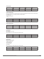
Get Trigger Level :
Set Alarm Delay:
Delay from detected alarm sound level before activating alarm relay.
n: 0 - 60 [10 sec] = 0 - 600 sec.
Automatic range adjustment :
> 60 = 60
ADR
CMD
VAR
SUM
MASTER
ADR
02
n
SUM
OBSERVER
ID
00
06
SUM
ADR
CMD
VAR
SUM
MASTER
ADR
12
x
SUM
OBSERVER
ID
12
n
SUM
Get Alarm Delay:
Set Relay Function:
Set the relay default in normally closed (NC) or normally open (NO) position.
n: 1 = NC (normally closed (default)), 0 = NO (normally open)
Automatic range adjustment:
> 1 = NO (normally open)
ADR
CMD
VAR
SUM
MASTER
ADR
03
n
SUM
OBSERVER
ID
00
06
SUM
Installation and User Guide for Gassonic Observer (BB 6017-09)
Page 17
Get Relay Function:
ADR
CMD
VAR
SUM
MASTER
ADR
13
x
SUM
OBSERVER
ID
13
n
SUM
Set Alarm Latching Function:
Function to hold alarm, instead of resetting alarm when sound level falls below trigger level. The alarm can be reset on the front panel
by activating the SET switch, or by sending “Reset Alarm” command on RS485.
n: 0 = OFF, 1 = ON
Automatic range adjustment:
> 1 = ON
ADR
CMD
VAR
SUM
MASTER
ADR
04
n
SUM
OBSERVER
ID
00
06
SUM
ADR
CMD
VAR
SUM
MASTER
ADR
14
x
SUM
OBSERVER
ID
14
n
SUM
Get Alarm Latching Function:
Get Sound Level:
Read current sound level in [dB].
n: 51 - 99 [dB]
Note: This function does not affect analog output or alarm relay output.
ADR
CMD
VAR
SUM
MASTER
ADR
20
x
SUM
OBSERVER
ID
20
n
SUM
Get Alarm Status:
Read current sound level in [dB].
n: Binary coded alarm status
- Bit 0: Low supply error
- Bit 1: Acoustical error
- Bit 2: Electrical error
- Bit 3: Inhibit
Note: This function does not affect analog output or alarm relay output.
ADR
CMD
VAR
SUM
MASTER
ADR
21
x
SUM
OBSERVER
ID
21
n
SUM
Installation and User Guide for Gassonic Observer Ultrasonic gas leak detector
Page 18
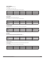
Get Box Temperature:
Read box temperature relative in [°C].
n: 0 - 121 [°C]
0 = -40°C, 120 = +80°C, 121 => +80°C
Note : This function does not affect analog output or alarm relay output.
ADR
CMD
VAR
SUM
MASTER
ADR
28
x
SUM
OBSERVER
ID
28
n
SUM
Get +24V supply:
Read Gassonic Observer power supply voltage in [V].
n: 13 - 28 [V]
Note : This function does not affect analog output or alarm relay output.
ADR
CMD
VAR
SUM
MASTER
ADR
32
x
SUM
OBSERVER
ID
32
n
SUM
Set to Factory Default:
Copy default values from “Service and Productions” registers to user data registers.
ADR
CMD
VAR
SUM
MASTER
ADR
30
x
SUM
OBSERVER
ID
00
06
SUM
Reset Alarm:
Reset alarm output that is hold by the “Alarm Latching” function.
Note: This function sets relays and analog output back to normal state.
ADR
CMD
VAR
SUM
MASTER
ADR
31
x
SUM
OBSERVER
ID
00
06
SUM
Forced Acoustic Test:
Start one transducer frequency sweep. Return max sound level in dB when sweep is finished.
n: <58-104 [dB]
Note: Set analog output to “inhibit” and disable gas alarm relay output.
ADR
CMD
VAR
SUM
MASTER
ADR
32
x
SUM
OBSERVER
ID
32
n
SUM
Installation and User Guide for Gassonic Observer (BB 6017-09)
Page 19
GASSONIC OBSERVER
ULTRASONIC GAS LEAK DETECTOR
From serial number: 1011-014
BB 6017-09
CAPITOL COPENHAGEN +45 4580 0831
GASSONIC A/S
Energivej 42 A
DK-2750 Ballerup
Denmark
Tel +45 44 700 910
Fax +45 44 700 911
[email protected]
www.gassonic.com