1
AFL2-W21A/AB-H61
IEI Te c h n o lo g y Co rp .
MODEL:
AFL2-W21A/AB-H61 S e rie s
Flat Bezel Panel PC with Intel® Core™ i7/ i5/ i3 and Pentium®
processor, Touch Screen, Wi-Fi, USB, Dual GbE LAN ,
RS-232/422/485, 2.0M pixels Camera,
HD Audio and RoHS
Us e r Ma n u a l
Page I
Re v. 1.00 - 16 Ap ril, 2013
AFL2-W21A/AB-H61
Re vis io n
Date
Version
Changes
16 April 2013
1.00
Initial release
Page II
AFL2-W21A/AB-H61
Co p yrig h t
COP YRIGHT NOTICE
The information in this document is subject to change without prior notice in order to
improve reliability, design and function and does not represent a commitment on the part
of the manufacturer.
In no event will the manufacturer be liable for direct, indirect, special, incidental, or
consequential damages arising out of the use or inability to use the product or
documentation, even if advised of the possibility of such damages.
This document contains proprietary information protected by copyright. All rights are
reserved. No part of this manual may be reproduced by any mechanical, electronic, or
other means in any form without prior written permission of the manufacturer.
TRADEMARKS
All registered trademarks and product names mentioned herein are used for identification
purposes only and may be trademarks and/or registered trademarks of their respective
owners.
Page III
AFL2-W21A/AB-H61
Ta b le o f Co n te n ts
1 INTRODUCTION.......................................................................................................... 1
1.1 AFL2-W21A/AB-H61 FLAT BEZEL PANEL PC OVERVIEW ........................................ 2
1.1.1 Model Variations ................................................................................................ 3
1.1.2 Features ............................................................................................................. 3
1.1.3 Light Fanless Technology Design ...................................................................... 4
1.2 EXTERNAL OVERVIEW ................................................................................................ 5
1.2.1 Front Panel ........................................................................................................ 5
1.2.1.1 Function Keys ............................................................................................. 5
1.2.2 Rear Panel ......................................................................................................... 6
1.2.3 Bottom Panel ...................................................................................................... 7
1.2.4 Left Side Panel ................................................................................................... 8
1.2.5 Right Side Panel ................................................................................................. 8
1.3 INTERNAL OVERVIEW ................................................................................................. 9
1.4 SYSTEM SPECIFICATIONS ............................................................................................ 9
1.5 DIMENSIONS ............................................................................................................. 12
2 LED LIGHT BAR (OPTIONAL) ............................................................................... 13
2.1 OVERVIEW................................................................................................................ 14
2.2 IEI LED LIGHT BAR DISPLAY SIMULATOR ............................................................... 14
2.3 IEI LED RUN ............................................................................................................ 22
2.4 LED CONTROL API .................................................................................................. 23
2.4.1 Introduction ...................................................................................................... 23
2.4.1.1 Programming Language Support .............................................................. 23
2.4.1.2 Application Content .................................................................................. 23
2.4.2 LED Control API Functions............................................................................. 23
2.4.2.1 LIGHTBAR_DriverInit ............................................................................ 23
2.4.2.2 LIGHTBAR_DriverUninit ........................................................................ 24
2.4.2.3 LIGHTBAR_DeviceInit ........................................................................... 24
2.4.2.4 LIGHTBAR_DeviceClose ........................................................................ 24
2.4.2.5 LIGHTBAR_Brightness_Single ............................................................... 25
2.4.2.6 LIGHTBAR_BLNK_Settings................................................................... 25
Page IV
AFL2-W21A/AB-H61
2.4.2.7 LIGHTBAR_BLNK_Type........................................................................ 26
2.4.2.8 LIGHTBAR_LED_ModeSet .................................................................... 26
2.4.3 Structures ......................................................................................................... 27
2.4.3.1 _LED_COLOR_INFO .............................................................................. 27
2.4.3.2 _LED_BLNK_SET ................................................................................... 27
2.4.3.3 _LED_BLNK_SET ................................................................................... 28
2.4.3.4 _LED_MODE_SETTINGS ...................................................................... 29
2.4.4 Programming Example .................................................................................... 29
2.4.4.1 Turn on LED - single ................................................................................ 29
2.4.4.2 Turn on LED - multiple............................................................................. 30
2.4.4.3 LED Blink - 1............................................................................................ 32
2.4.4.4 LED Blink - 2............................................................................................ 33
3 UNPACKING ............................................................................................................... 35
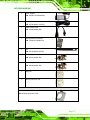
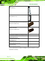
3.1 UNPACKING .............................................................................................................. 36
3.1.1 Packing List ..................................................................................................... 36
4 INSTALLATION ......................................................................................................... 39
4.1 ANTI-STATIC PRECAUTIONS ...................................................................................... 40
4.2 INSTALLATION PRECAUTIONS ................................................................................... 40
4.3 INSTALLATION AND CONFIGURATION STEPS ............................................................. 41
4.4 HDD INSTALLATION................................................................................................. 41
4.5 K-TYPE TEMPERATURE SENSOR INSTALLATION ....................................................... 44
4.6 RFID READER (OPTIONAL) ...................................................................................... 45
4.7 DVD-ROM INSTALLATION (OPTIONAL) .................................................................. 46
4.8 AT/ATX MODE SELECTION ...................................................................................... 48
4.8.1 AT Power Mode ................................................................................................ 48
4.8.2 ATX Power Mode ............................................................................................. 49
4.9 CLEAR CMOS .......................................................................................................... 49
4.10 RESET THE SYSTEM ................................................................................................ 50
4.11 POWERING ON THE SYSTEM ................................................................................... 50
4.12 POWERING OFF THE SYSTEM .................................................................................. 50
4.13 MOUNTING THE SYSTEM ........................................................................................ 51
4.13.1 Wall Mounting ................................................................................................ 51
4.13.2 Panel Mounting .............................................................................................. 54
Page V
AFL2-W21A/AB-H61
4.13.3 Stand Mounting .............................................................................................. 56
4.13.4 Arm Mounting ................................................................................................ 57
4.14 EXTERNAL PERIPHERAL DEVICE CONNECTION ...................................................... 59
4.14.1 Audio Connection ........................................................................................... 59
4.14.2 HDMI Device Connection.............................................................................. 60
4.14.3 LAN Connection ............................................................................................. 62
4.14.4 Serial Device Connection .............................................................................. 63
4.14.5 USB Device Connection ................................................................................. 65
4.14.6 VGA Monitor Connection .............................................................................. 67
5 SYSTEM MOTHERBOARD ..................................................................................... 69
5.1 OVERVIEW................................................................................................................ 70
5.1.1 Layout .............................................................................................................. 70
5.1.2 Peripheral Interface Connectors ..................................................................... 71
5.2 INTERNAL PERIPHERAL CONNECTORS ...................................................................... 73
5.2.1 Auto-Dimming Connector ................................................................................ 73
5.2.2 Battery Connector ............................................................................................ 74
5.2.3 BIOS Programming Connector ........................................................................ 74
5.2.4 Bluetooth Connector ........................................................................................ 75
5.2.5 CPU Fan Connector ........................................................................................ 76
5.2.6 DDR3 SO-DIMM Slots .................................................................................... 77
5.2.7 Debug Port Connector ..................................................................................... 78
5.2.8 Digital Microphone Connector ........................................................................ 79
5.2.9 EC Debug Connector ....................................................................................... 80
5.2.10 EC Programming Connector ......................................................................... 81
5.2.11 Hotkey Connector ........................................................................................... 82
5.2.12 Hotkey LED Connector .................................................................................. 82
5.2.13 JSATA Connector ........................................................................................... 83
5.2.14 K Type Thermocouple Connector .................................................................. 84
5.2.15 LVDS Connector ............................................................................................ 86
5.2.16 LVDS Backlight Inverter Connector .............................................................. 87
5.2.17 LED Connector .............................................................................................. 88
5.2.18 Light Bar Connectors ..................................................................................... 89
5.2.19 LOGO LED Connector .................................................................................. 90
5.2.20 Mini USB Connector ...................................................................................... 91
Page VI
AFL2-W21A/AB-H61
5.2.21 PCIe Mini Card Slot ...................................................................................... 93
5.2.22 Power Button Connector................................................................................ 94
5.2.23 RFID Connector............................................................................................. 94
5.2.24 SATA 3Gb/s Drive Connectors ....................................................................... 95
5.2.25 SATA Power Connector .................................................................................. 96
5.2.26 Speaker Connector ......................................................................................... 97
5.2.27 Touch panel connector (5-wire resistive type)............................................... 98
5.2.28 Touch panel connector (projected capacitive type) ....................................... 99
5.2.29 TPM Connector ............................................................................................ 100
5.2.30 Web Camera Connector ............................................................................... 101
5.3 JUMPER SETTINGS .................................................................................................. 103
5.3.1 LVDS Voltage Selection.................................................................................. 103
5.3.2 LCD panel selection ....................................................................................... 104
6 SYSTEM MAINTENANCE ..................................................................................... 106
6.1 SYSTEM MAINTENANCE INTRODUCTION ................................................................ 107
6.2 ANTI-STATIC PRECAUTIONS .................................................................................... 107
6.3 TURN OFF THE POWER ............................................................................................ 108
6.4 OPENING THE SYSTEM ............................................................................................ 108
6.4.1 Removing the Back Cover .............................................................................. 108
6.4.2 Removing the Internal Aluminum Cover ........................................................ 109
6.5 REPLACING COMPONENTS .......................................................................................110
6.5.1 Memory Module Replacement ........................................................................ 110
6.5.2 WLAN Card Replacement ............................................................................... 111
6.6 REINSTALLING THE COVERS ....................................................................................114
7 BIOS SETUP ............................................................................................................... 115
7.1 INTRODUCTION........................................................................................................116
7.1.1 Starting Setup .................................................................................................. 116
7.1.2 Using Setup ..................................................................................................... 116
7.1.3 Getting Help .................................................................................................... 117
7.1.4 Unable to Reboot after Configuration Changes ............................................. 117
7.1.5 BIOS Menu Bar ............................................................................................... 117
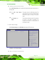
7.2 MAIN .......................................................................................................................118
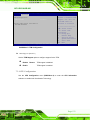
7.3 ADVANCED ..............................................................................................................119
Page VII
AFL2-W21A/AB-H61
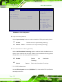
7.3.1 ACPI Settings ................................................................................................. 120
7.3.2 RTC Wake Settings ......................................................................................... 121
7.3.3 Trusted Computing ......................................................................................... 122
7.3.4 CPU Configuration ........................................................................................ 123
7.3.4.1 CPU Information ..................................................................................... 124
7.3.5 SATA Configuration ....................................................................................... 126
7.3.6 Intel TXT (LT) Configuration ......................................................................... 127
7.3.7 USB Configuration......................................................................................... 128
7.3.8 F81216 Super IO Configuration .................................................................... 129
7.3.8.1 Serial Port n Configuration ..................................................................... 129
7.3.9 H/W Monitor .................................................................................................. 132
7.3.10 Serial Port Console Redirection .................................................................. 136
7.3.10.1 Console Redirection Settings ................................................................ 137
7.4 IEI FEATURE ........................................................................................................... 140
7.5 CHIPSET ................................................................................................................. 140
7.5.1 Northbridge Configuration ............................................................................ 142
7.5.2 Southbridge Configuration ............................................................................ 142
7.5.3 Integrated Graphics ....................................................................................... 145
7.6 BOOT...................................................................................................................... 147
7.7 SECURITY ............................................................................................................... 149
7.8 SAVE & EXIT .......................................................................................................... 150
8 SOFTWARE DRIVERS ............................................................................................ 152
8.1 AVAILABLE SOFTWARE DRIVERS ............................................................................ 153
8.2 STARTING THE DRIVER PROGRAM .......................................................................... 153
8.3 CHIPSET DRIVER INSTALLATION ............................................................................. 154
8.4 GRAPHICS DRIVER INSTALLATION .......................................................................... 158
8.5 AUDIO DRIVER INSTALLATION ............................................................................... 163
8.6 LAN DRIVER INSTALLATION .................................................................................. 165
8.7 INTEL® MANAGEMENT ENGINE COMPONENTS INSTALLATION............................... 167
8.8 USB 3.0 DRIVER INSTALLATION............................................................................. 170
8.9 WI-FI DRIVER INSTALLATION ................................................................................. 173
8.10 LED BAR DRIVER INSTALLATION ........................................................................ 177
8.11 AMCAP DRIVER INSTALLATION ........................................................................... 180
9 COOLING MANAGEMENT CONSOLE (ICMC) ................................................ 182
Page VIII
AFL2-W21A/AB-H61
9.1 OVERVIEW.............................................................................................................. 183
9.1.1 iCMC Installation .......................................................................................... 183
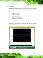
9.2 ICMC OVERVIEW ................................................................................................... 186
9.2.1 Information Panel .......................................................................................... 186
9.2.2 Chart Panel .................................................................................................... 189
A SAFETY PRECAUTIONS ....................................................................................... 191
A.1 SAFETY PRECAUTIONS .......................................................................................... 192
A.1.1 General Safety Precautions ........................................................................... 192
A.1.2 Anti-static Precautions .................................................................................. 193
A.1.3 Product Disposal ........................................................................................... 194
A.2 MAINTENANCE AND CLEANING PRECAUTIONS ...................................................... 194
A.2.1 Maintenance and Cleaning............................................................................ 194
A.2.2 Cleaning Tools ............................................................................................... 195
B BIOS MENU OPTIONS ........................................................................................... 196
C ONE KEY RECOVERY ........................................................................................... 199
C.1 ONE KEY RECOVERY INTRODUCTION .................................................................... 200
C.1.1 System Requirement ...................................................................................... 201
C.1.2 Supported Operating System ......................................................................... 202
C.2 SETUP PROCEDURE FOR WINDOWS ........................................................................ 203
C.2.1 Hardware and BIOS Setup ............................................................................ 204
C.2.2 Create Partitions ........................................................................................... 204
C.2.3 Install Operating System, Drivers and Applications ..................................... 208
C.2.4 Building the Recovery Partition .................................................................... 209
C.2.5 Create Factory Default Image ....................................................................... 211
C.3 AUTO RECOVERY SETUP PROCEDURE .................................................................... 216
C.4 SETUP PROCEDURE FOR LINUX .............................................................................. 220
C.5 RECOVERY TOOL FUNCTIONS ................................................................................ 224
C.5.1 Factory Restore ............................................................................................. 225
C.5.2 Backup System ............................................................................................... 226
C.5.3 Restore Your Last Backup .............................................................................. 227
C.5.4 Manual .......................................................................................................... 228
C.6 RESTORE SYSTEMS FROM A LINUX SERVER THROUGH LAN .................................. 229
C.6.1 Configure DHCP Server Settings .................................................................. 230
Page IX
AFL2-W21A/AB-H61
C.6.2 Configure TFTP Settings ............................................................................... 231
C.6.3 Configure One Key Recovery Server Settings ............................................... 232
C.6.4 Start the DHCP, TFTP and HTTP ................................................................. 233
C.6.5 Create Shared Directory................................................................................ 233
C.6.6 Setup a Client System for Auto Recovery ...................................................... 234
C.7 OTHER INFORMATION ............................................................................................ 237
C.7.1 Using AHCI Mode or ALi M5283 / VIA VT6421A Controller ...................... 237
C.7.2 System Memory Requirement ........................................................................ 239
D HAZARDOUS MATERIALS DISCLOSURE ....................................................... 240
D.1 HAZARDOUS MATERIAL DISCLOSURE TABLE FOR IPB PRODUCTS CERTIFIED AS
ROHS COMPLIANT UNDER 2002/95/EC WITHOUT MERCURY ..................................... 241
Page X
AFL2-W21A/AB-H61
Lis t o f Fig u re s
Figure 1-1: AFL2-W21A/AB-H61 Flat Bezel Panel PC .................................................................2
Figure 1-2: AFL2-W21A/AB-H61 Front View ................................................................................5
Figure 1-3: Function Keys .............................................................................................................5
Figure 1-4: AFL2-W21A/AB-H61 Rear View ..................................................................................6
Figure 1-5: AFL2-W21A/AB-H61 Bottom Panel ............................................................................7
Figure 1-6: AFL2-W21A/AB-H61 Left Side Panel .........................................................................8
Figure 1-7: AFL2-W21A/AB-H61 Right Side Panel ......................................................................8
Figure 1-8: AFL2-W21A/AB-H61 Dimensions (mm) ...................................................................12
Figure 2-1: The Setup Wizard Starts ...........................................................................................14
Figure 2-2: Select Installation Folder Screen ............................................................................15
Figure 2-3: Confirm Installation Screen .....................................................................................15
Figure 2-4: Installation Complete ................................................................................................16
Figure 2-5: iEi LED Light Bar Display Simulator .......................................................................17
Figure 2-6: Color Setting Area .....................................................................................................18
Figure 2-7: Color Palette ..............................................................................................................18
Figure 2-8: Simulate the LED Light .............................................................................................19
Figure 2-9: Set the Left LEDs ......................................................................................................19
Figure 2-10: Set All the LEDs ......................................................................................................20
Figure 2-11: Light Duration ..........................................................................................................20
Figure 2-12: Add new command .................................................................................................21
Figure 2-13: Add Loop Start ........................................................................................................21
Figure 2-14: Add Loop End ..........................................................................................................22
Figure 2-15: iEi LED RUN Software.............................................................................................22
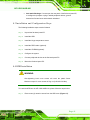
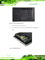
Figure 4-1: HDD Cover Retention Screws ..................................................................................42
Figure 4-2: HDD Bracket Screw ...................................................................................................42
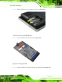
Figure 4-3: Removing the HDD Bracket .....................................................................................43
Figure 4-4: Inserting the HDD ......................................................................................................43
Figure 4-5: Securing the HDD ......................................................................................................44
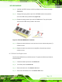
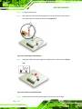
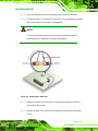
Figure 4-6: Insert the K-type Temperature Sensor Cable .........................................................45
Figure 4-7: Connect the RFID USB cable ...................................................................................45
Figure 4-8: Install the RFID module ............................................................................................46
Page XI
AFL2-W21A/AB-H61
Figure 4-9: DVD-ROM Bracket .....................................................................................................46
Figure 4-10: Remove the HDD Bracket .......................................................................................47
Figure 4-11: Secure the DVD-ROM..............................................................................................47
Figure 4-12: DVD-ROM Installation .............................................................................................48
Figure 4-13: AT/ATX Switch Location.........................................................................................48
Figure 4-14: Clear CMOS Switch Location .................................................................................49
Figure 4-15: Reset Button Location ............................................................................................50
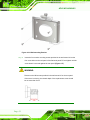
Figure 4-16: Wall-mounting Bracket ...........................................................................................52
Figure 4-17: Chassis Support Screws ........................................................................................53
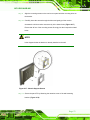
Figure 4-18: Secure the Panel PC ...............................................................................................54
Figure 4-19: Cutout Dimensions .................................................................................................54
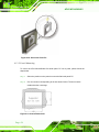
Figure 4-20: Tighten the Panel Mounting Clamp Screws .........................................................55
Figure 4-21: Mounting screw location ........................................................................................56
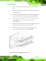
Figure 4-22: Stand Mounting (Stand-A/Bxx) ..............................................................................57
Figure 4-23: Arm Mounting Retention Screw Holes ..................................................................58
Figure 4-24: Arm Mounting (ARM-11-RS) ...................................................................................59
Figure 4-25: Audio Connector .....................................................................................................60
Figure 4-26: HDMI Connection ....................................................................................................61
Figure 4-27: LAN Connection ......................................................................................................62
Figure 4-28: DB-9 Serial Port Connector ....................................................................................64
Figure 4-29: USB Device Connection .........................................................................................66
Figure 4-30: VGA Connector .......................................................................................................68
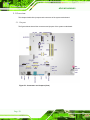
Figure 5-1: Connectors and Jumpers (front) .............................................................................70
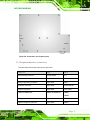
Figure 5-2: Connectors and Jumpers (rear) ..............................................................................71
Figure 5-3: Auto-dimming Connector Pinout Location ............................................................73
Figure 5-4: Battery Connector Locations ...................................................................................74
Figure 5-5: BIOS Programming Connector Location ................................................................75
Figure 5-6: Bluetooth Connector Location ................................................................................76
Figure 5-7: CPU Fan Connector Location ..................................................................................77
Figure 5-8: DDR3 DIMM Slot Locations ......................................................................................78
Figure 5-9: Debug Port Connector Location ..............................................................................78
Figure 5-10: Digital Microphone Connector Location...............................................................79
Figure 5-11: Debug Port Connector Location ............................................................................80
Figure 5-12: EC Programming Connector Location ..................................................................81
Figure 5-13: Hotkey Connector Location ...................................................................................82
Page XII
AFL2-W21A/AB-H61
Figure 5-14: Hotkey LED Connector Location ...........................................................................83
Figure 5-15: JSATA Connector Location ...................................................................................84
Figure 5-16: K Type Thermocouple Connector Location .........................................................85
Figure 5-17: K Type Thermocouple Connector Location .........................................................85
Figure 5-18: LVDS Connector Location......................................................................................86
Figure 5-19: LVDS Backlight Inverter Connector Location ......................................................88
Figure 5-20: LED Connector Location ........................................................................................89
Figure 5-21: LED Bar Connectors Location ...............................................................................90
Figure 5-22: LOGO LED Connector Location ............................................................................91
Figure 5-23: Mini USB Connector Location (MINUSB2)............................................................92
Figure 5-24: Mini USB Connector Location (MINUSB1)............................................................92
Figure 5-25: PCIe Mini Card Slot Location .................................................................................93
Figure 5-26: Power Button Connector Location ........................................................................94
Figure 5-27: RFID Connector Location .......................................................................................95
Figure 5-28: SATA 3Gb/s Drive Connector Location ................................................................96
Figure 5-29: SATA Power Connector Locations .......................................................................97
Figure 5-30: Speaker Connector Location .................................................................................98
Figure 5-31: Touch Panel Connector Location ..........................................................................99
Figure 5-32: Touch Panel Connector Location ........................................................................100
Figure 5-33: TPM Connector Location......................................................................................101
Figure 5-34: Web Camera Connector Location .......................................................................102
Figure 5-35: LVDS Voltage Selection Jumper Location .........................................................104
Figure 5-36: LCD panel Selection Jumper Location ...............................................................105
Figure 6-1: Back Cover Retention Screws ...............................................................................109
Figure 6-2: Internal Cover Retention Screws ...........................................................................109
Figure 6-3: Internal Components ..............................................................................................110
Figure 6-4: DDR SO-DIMM Module Installation ........................................................................111
Figure 6-5: Releasing the WLAN Card ......................................................................................112
Figure 6-6: Removing the WLAN card ......................................................................................112
Figure 6-7: Attaching the Antennas ..........................................................................................113
Figure 8-1: Drivers ......................................................................................................................154
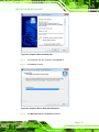
Figure 8-2: Chipset Driver Screen .............................................................................................155
Figure 8-3: Chipset Driver Welcome Screen ............................................................................155
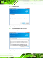
Figure 8-4: Chipset Driver License Agreement .......................................................................156
Figure 8-5: Chipset Driver Read Me File ..................................................................................157
Page XIII
AFL2-W21A/AB-H61
Figure 8-6: Chipset Driver Setup Operations ..........................................................................157
Figure 8-7: Chipset Driver Installation Finish Screen .............................................................158
Figure 8-8: Graphics Driver Read Me File ................................................................................159
Figure 8-9: Graphics Driver Setup Files Extracted .................................................................159
Figure 8-10: Graphics Driver Welcome Screen .......................................................................160
Figure 8-11: Graphics Driver License Agreement ...................................................................160
Figure 8-12: Graphics Driver Read Me File ..............................................................................161
Figure 8-13: Graphics Driver Setup Operations ......................................................................162
Figure 8-14: Graphics Driver Installation Finish Screen ........................................................162
Figure 8-15: Audio Driver Welcome Screen .............................................................................163
Figure 8-16: Audio Driver Installation.......................................................................................164
Figure 8-17: Audio Driver Installation Complete .....................................................................164
Figure 8-18: LAN Driver Welcome Screen ...............................................................................165
Figure 8-19: LAN Driver Ready to Install Screen .....................................................................166
Figure 8-20: LAN Driver Setup Status Screen .........................................................................166
Figure 8-21: LAN Driver Installation Complete ........................................................................167
Figure 8-22: Intel® ME Driver Welcome Screen ......................................................................168
Figure 8-23: Intel® ME Driver License Agreement ..................................................................168
Figure 8-24: Intel® ME Driver Read Me File .............................................................................169
Figure 8-25: Intel® ME Driver Setup Operations .....................................................................169
Figure 8-26: Intel® ME Driver Installation Finish Screen .......................................................170
Figure 8-27: USB 3.0 Driver Welcome Screen .........................................................................171
Figure 8-28: USB 3.0 Driver License Agreement .....................................................................171
Figure 8-29: USB 3.0 Driver Installation ...................................................................................172
Figure 8-30: USB 3.0 Driver Update Complete ........................................................................172
Figure 8-31: License Agreement ...............................................................................................173
Figure 8-32: Setup Type .............................................................................................................174
Figure 8-33: Configuration Tool ................................................................................................174
Figure 8-34: Ready to Install the Program ...............................................................................175
Figure 8-35: Setup Status ..........................................................................................................176
Figure 8-36: Installation Complete ............................................................................................176
Figure 8-37: The InstallShield Wizard Starts ...........................................................................177
Figure 8-38: Welcome Screen ...................................................................................................178
Figure 8-39: Ready to Install ......................................................................................................178
Figure 8-40: Installation .............................................................................................................179
Page XIV
AFL2-W21A/AB-H61
Figure 8-41: Installation Complete ............................................................................................179
Figure 8-42: AMCap Driver Welcome Screen ..........................................................................180
Figure 8-43: AMCap Driver Choose Install Location ...............................................................181
Figure 8-44: AMCap Driver Installation Complete ...................................................................181
Figure 9-1: Cooling Management Console Setup Wizard.......................................................183
Figure 9-2: Select Installation Folder........................................................................................184
Figure 9-3: Confirm Installation ................................................................................................184
Figure 9-4: Installation Complete ..............................................................................................185
Figure 9-5: Restart the System..................................................................................................185
Figure 9-6: Cooling Management Console Icon ......................................................................186
Figure 9-7: iCMC .........................................................................................................................186
Figure 9-8: iCMC Information Panel..........................................................................................187
Figure 9-9: iCMC – Chart Panel .................................................................................................189
Figure 9-10: iCMC – Time Interval Adjustment ........................................................................190
Figure C-1: IEI One Key Recovery Tool Menu .........................................................................200
Figure C-2: Launching the Recovery Tool ...............................................................................205
Figure C-3: Recovery Tool Setup Menu ...................................................................................205
Figure C-4: Command Prompt ..................................................................................................206
Figure C-5: Partition Creation Commands ...............................................................................207
Figure C-6: Launching the Recovery Tool ...............................................................................209
Figure C-7: Manual Recovery Environment for Windows ......................................................209
Figure C-8: Building the Recovery Partition ............................................................................210
Figure C-9: Press Any Key to Continue ...................................................................................210
Figure C-10: Press F3 to Boot into Recovery Mode................................................................211
Figure C-11: Recovery Tool Menu ............................................................................................211
Figure C-12: About Symantec Ghost Window .........................................................................212
Figure C-13: Symantec Ghost Path ..........................................................................................212
Figure C-14: Select a Local Source Drive ................................................................................213
Figure C-15: Select a Source Partition from Basic Drive .......................................................213
Figure C-16: File Name to Copy Image to ................................................................................214
Figure C-17: Compress Image ...................................................................................................214
Figure C-18: Image Creation Confirmation ..............................................................................215
Figure C-19: Image Creation Complete ....................................................................................215
Figure C-20: Image Creation Complete ....................................................................................215
Figure C-21: Press Any Key to Continue .................................................................................216
Page XV
AFL2-W21A/AB-H61
Figure C-22: Auto Recovery Utility ...........................................................................................217
Figure C-23: Launching the Recovery Tool .............................................................................217
Figure C-24: Auto Recovery Environment for Windows ........................................................217
Figure C-25: Building the Auto Recovery Partition .................................................................218
Figure C-26: Factory Default Image Confirmation ..................................................................218
Figure C-27: Image Creation Complete ....................................................................................219
Figure C-28: Press any key to continue ...................................................................................219
Figure C-29: Partitions for Linux...............................................................................................221
Figure C-30: Manual Recovery Environment for Linux ..........................................................222
Figure C-31: Access menu.lst in Linux (Text Mode) ...............................................................223
Figure C-32: Recovery Tool Menu ............................................................................................223
Figure C-33: Recovery Tool Main Menu ...................................................................................224
Figure C-34: Restore Factory Default .......................................................................................225
Figure C-35: Recovery Complete Window ...............................................................................226
Figure C-36: Backup System .....................................................................................................226
Figure C-37: System Backup Complete Window ....................................................................227
Figure C-38: Restore Backup ....................................................................................................227
Figure C-39: Restore System Backup Complete Window ......................................................228
Figure C-40: Symantec Ghost Window ....................................................................................228
Page XVI
AFL2-W21A/AB-H61
Lis t o f Ta b le s
Table 1-1: AFL2-W21A/AB-H61 Model Variations ........................................................................3
Table 1-2: Function Key Descriptions ..........................................................................................6
Table 1-3: System Specifications................................................................................................11
Table 2-1: LED Simulator Software Description ........................................................................18
Table 4-1: HDMI Pinouts ..............................................................................................................61
Table 4-2: LAN1 Pinouts ..............................................................................................................63
Table 4-3: LAN2 Pinouts ..............................................................................................................63
Table 4-4: RS-232 Serial Ports Pinouts (COM1, COM2) ............................................................64
Table 4-5: RS-422/485 Serial Port Pinouts (COM3) ...................................................................65
Table 4-6: USB 2.0 connectors Pinouts (bottom panel) ...........................................................66
Table 4-7: USB 2.0 connectors Pinouts (left side panel) ..........................................................66
Table 4-8: USB 3.0 connectors Pinouts .....................................................................................67
Table 4-9: VGA Pinouts ................................................................................................................68
Table 5-1: Peripheral Interface Connectors ...............................................................................72
Table 5-2: Auto-dimming Connector Pinouts ............................................................................73
Table 5-3: Battery Connector Pinouts ........................................................................................74
Table 5-4: BIOS Programming Connector Pinouts ...................................................................75
Table 5-5: Bluetooth Connector Pinouts ....................................................................................76
Table 5-6: CPU Fan Connector Pinouts .....................................................................................77
Table 5-7: Debug Port Connector Pinouts .................................................................................79
Table 5-8: Digital Microphone Connector Pinouts ....................................................................80
Table 5-9: Debug Port Connector Pinouts .................................................................................81
Table 5-10: EC Programming Connector Pinouts .....................................................................81
Table 5-11: Hotkey Connector Pinouts.......................................................................................82
Table 5-12: Hotkey LED Connector Pinouts ..............................................................................83
Table 5-13: JSATA Connector Pinouts .......................................................................................84
Table 5-14: K Type Thermocouple Connector Pinouts.............................................................86
Table 5-15: LVDS Connector Pinouts .........................................................................................87
Table 5-16: LVDS Backlight Inverter Connector Pinouts .........................................................88
Table 5-17: LED Connector Pinouts ...........................................................................................89
Table 5-18: LED Bar Connectors Pinouts ..................................................................................90
Page XVII
AFL2-W21A/AB-H61
Table 5-19: LOGO LED Connector Pinouts ................................................................................91
Table 5-20: Mini USB Connector Pinouts (MINUSB2) ...............................................................92
Table 5-21: Mini USB Connector Pinouts (MINUSB1) ...............................................................93
Table 5-22: Power Button Connector Pinouts ...........................................................................94
Table 5-23: RFID Connector Pinouts ..........................................................................................95
Table 5-24: SATA 3Gb/s Drive Connector Pinouts ....................................................................96
Table 5-25: SATA Power Connector Pinouts .............................................................................97
Table 5-26: Speaker Connector Pinouts ....................................................................................98
Table 5-27: Touch Panel Connector Pinouts .............................................................................99
Table 5-28: Touch Panel Connector Pinouts ...........................................................................100
Table 5-29: TPM Connector Pinouts .........................................................................................101
Table 5-30: Web Camera Connector Pinouts ...........................................................................102
Table 5-31: Jumpers ...................................................................................................................103
Table 5-32: LVDS Voltage Selection Jumper Settings ............................................................104
Table 5-33: LCD panel Selection Jumper Settings..................................................................104
Table 7-1: BIOS Navigation Keys ..............................................................................................117
Table 9-1: iCMC Information Panel Description ......................................................................188
Page XVIII
AFL2-W21A/AB-H61
Lis t o f BIOS Me n u s
BIOS Menu 1: Main .....................................................................................................................118
BIOS Menu 2: Advanced ............................................................................................................120
BIOS Menu 3: ACPI Configuration ............................................................................................120
BIOS Menu 4: RTC Wake Settings ............................................................................................121
BIOS Menu 5: TPM Configuration .............................................................................................123
BIOS Menu 6: CPU Configuration .............................................................................................124
BIOS Menu 7: CPU Configuration .............................................................................................125
BIOS Menu 8: IDE Configuration ...............................................................................................126
BIOS Menu 9: Intel TXT(LT) Configuration...............................................................................127
BIOS Menu 10: USB Configuration ...........................................................................................128
BIOS Menu 11: Super IO Configuration....................................................................................129
BIOS Menu 12: Serial Port n Configuration Menu ...................................................................129
BIOS Menu 13: Hardware Health Configuration ......................................................................132
BIOS Menu 14: Serial Port Console Redirection .....................................................................137
BIOS Menu 15: Console Redirection Settings .........................................................................138
BIOS Menu 16: iEi Feature .........................................................................................................140
BIOS Menu 17: Chipset ..............................................................................................................141
BIOS Menu 18: Northbridge Chipset Configuration ................................................................142
BIOS Menu 19: Southbridge Chipset Configuration ...............................................................143
BIOS Menu 20: Integrated Graphics .........................................................................................146
BIOS Menu 21: Boot ...................................................................................................................147
BIOS Menu 22: Security .............................................................................................................149
BIOS Menu 23: Exit .....................................................................................................................150
BIOS Menu 24: iEi Feature .........................................................................................................220
Page XV
AFL2-W21A/AB-H61
Chapter
1
1 In tro d u c tio n
Page 1
AFL2-W21A/AB-H61
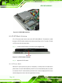
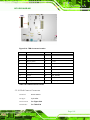
1.1 AFL2-W21A/AB-H61 Fla t Be ze l P a n e l P C Ove rview
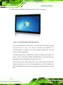
Figure 1-1: AFL2-W21A/AB-H61 Flat Bezel Panel PC
The AFL2-W21A/AB-H61 is an Intel® Core™ i7/i5/i3 and Pentium® processor powered
flat bezel panel PC with a rich variety of functions and peripherals. The
AFL2-W21A/AB-H61 is designed for easy and simplified integration into kiosk and
point-of-sales (POS) applications.
An Intel® H61 chipset ensures optimal memory, graphics, and peripheral I/O support. The
system comes with 4GB DDR3 1333MHz SO-DIMMs (2GB x 2) ensuring smooth data
throughputs with reduced bottlenecks and fast system access.
Three serial ports, three external USB 2.0 ports and two external USB 3.0 ports ensure
simplified connectivity to a variety of external peripheral devices. Wi-Fi capabilities and
dual RJ-45 Ethernet connectors provide the system with smooth connection to an external
LAN.
Page 2
AFL2-W21A/AB-H61
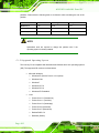
1.1.1 Mo d e l Va ria tio n s
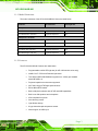
The model variations of the AFL2-W21A/AB-H61 Series are listed below.
Model No.
Touch Screen
LED Light Bar
AFL2-W21A-H61-i5/PC-R10
Projected capacitive
Yes
AFL2-W21AB-H61-i5/PC-R10
Projected capacitive
No
AFL2-W21A-H61-i3/PC-R10
Projected capacitive
Yes
AFL2-W21AB-H61-i3/PC-R10
Projected capacitive
No
AFL2-W21A-H61-P/PC-R10
Projected capacitive
Yes
AFL2-W21AB-H61-P/PC-R10
Projected capacitive
No
Intel® Core™ i5 Series
Intel® Core™ i3 Series
Intel® Pentium® G6xxT Series
Table 1-1: AFL2-W21A/AB-H61 Model Variations
1.1.2 Fe a tu re s
The AFL2-W21A/AB-H61 features are listed below:
Programmable colorful LED light bar (for AFL2-W21A-H61 series only)
Intel® Core™ i7/i5/i3 and Pentium® processor
Two 204-pin DDR3 SO-DIMM slot (system max. 16GB), pre-installed
with 4GB (2GB x 2)
Projected capacitive touchscreen supported
Wi-Fi 802.11b/g/n 2T2R high speed wireless
EM or Mifare RFID reader
Built-in 2M pixels webcam with AF, AE and AWB capabilities
Built-in two 3W speakers and microphone
IP64 compliant front panel
Auto dimming control
Light fanless design
K-type thermalcouple temperature sensor
Wide range 9~36 VDC input
Page 3
AFL2-W21A/AB-H61
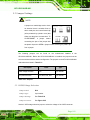
1.1.3 Lig h t Fa n le s s Te c h n o lo g y De s ig n
AFL2-W21A/AB-H61 series panel PCs are designed with light fanless technology. The
light fanless technology utilizes K-type thermocouple temperature sensor to detect
environment temperature and control fan operation, enhancing system stability and
remote environment control. The relative errors between the detect environment
temperature and the actual environment temperature are no more than ±5 degrees. When
the environment temperature is lower than default temperature setting, the fan will be
switched off, showing the advantage of quiet and dust free from fanless mode. While the
environment temperature is higher, the smart fan will be turned on to speed up heat
emission. The default temperature is 32 C and the setting can be adjusted in BIOS. See
Section 7.3.9. The systems can be easily implemented in the working environments that
require quiet and avoid dirt, like clean room, indoor HMI, and hospital.
Page 4
AFL2-W21A/AB-H61
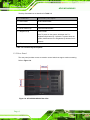
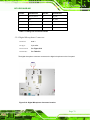
1.2 Exte rn a l Ove rview
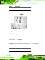
1.2.1 Fro n t P a n e l
The front side of the AFL2-W21A/AB-H61 is a flat bezel panel TFT LCD screen
surrounded by a PC/ABS plastic frame. The LED light bars are for AFL2-W21A-H61 series
only.
Figure 1-2: AFL2-W21A/AB-H61 Front View
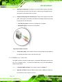
1.2.1.1 Fu n c tio n Ke ys
The corresponding Function Keys are located under the bottom right hand corner of the
LCD screen (Figure 1-3).
Figure 1-3: Function Keys
Page 5
AFL2-W21A/AB-H61
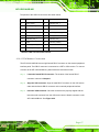
The Keys Combinations are described in Table 1-2:
Ke y Co m b in a tio n
Fu n c tio n Ke y De s c rip tio n
Fn + LCD On/Off
RFID Enable/Disable
Fn + Audio Volume Down
Audio Mute
Fn + Audio Volume Up
Camera Enable/Disable
Fn + Brightness Up
Power On/Off
Note: To power on the system, hold down the Fn +
Brightness Up buttons for 3 seconds. To power down the
system, hold down the FN + Brightness Up buttons for six
seconds.
Fn:
The function key can maintain for 2 sec.
Table 1-2: Function Key Descriptions
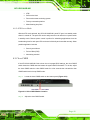
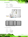
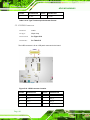
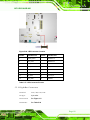
1.2.2 Re a r P a n e l
The rear panel provides access to retention screw holes that support various mounting.
Refer to Figure 1-4.
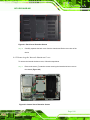
Figure 1-4: AFL2-W21A/AB-H61 Rear View
Page 6
AFL2-W21A/AB-H61
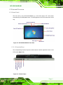
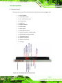
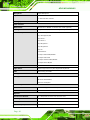
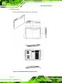
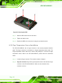
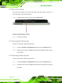
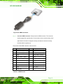
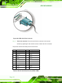
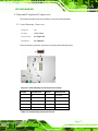
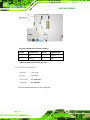
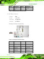
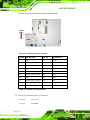
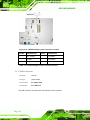
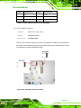
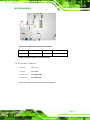
1.2.3 Bo tto m P a n e l
The bottom panel of the AFL2-W21A/AB-H61 has the following features (Figure 1-5):
1 x AT/ATX Switch
1 x Clear CMOS switch
1 x 9V ~ 36V DC power jack
6 x Function keys
1 x HDMI port
1 x K-type connector
1 x Power button
1 x Reset button
1 x RJ-45 LAN connector
2 x RS-232 connectors (COM1,COM2)
1 x RS-422/485 connector (COM3)
1 x Temperature sensor
2 x USB 2.0 connectors
2 x USB 3.0 connectors
1 x VGA port
Figure 1-5: AFL2-W21A/AB-H61 Bottom Panel
Page 7
AFL2-W21A/AB-H61
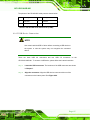
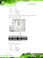
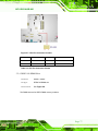
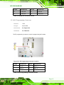
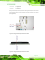
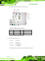
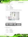
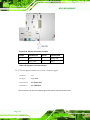
1.2.4 Le ft S id e P a ne l
The left side panel of the AFL2-W21A/AB-H61 has the following features (Figure 1-6):
2 x Audio jacks (Line out, MIC)
1 x RJ-45 LAN connector
1 x USB 2.0 connector
Figure 1-6: AFL2-W21A/AB-H61 Left Side Panel
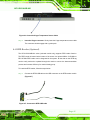
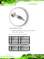
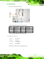
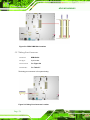
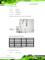
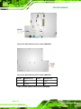
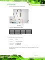
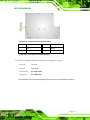
1.2.5 Rig h t S id e P a ne l
The right side panel of the AFL2-W21A/AB-H61 provides access to the DVD-ROM bay
(optional) (Figure 1-7):
Figure 1-7: AFL2-W21A/AB-H61 Right Side Panel
Page 8
AFL2-W21A/AB-H61
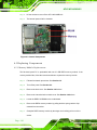
1.3 In te rn a l Ove rview
The AFL2-W21A/AB-H61 has the following components installed internally:
1 x Motherboard
2 x 2.0 GB 1333 MHz DDR3 SO-DIMMs
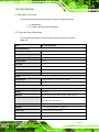
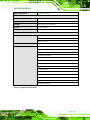
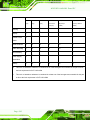
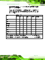
1.4 S ys te m Sp e c ific a tio n s
The technical specifications for the AFL2-W21A/AB-H61 systems are listed in
Table 1-3.
Model
AFL2-W21A/AB-H61
LCD Specifications
LCD Display
W21.5” (16:9)
Max Resolution
1920(W) x 1080(H)
Brightness (cd/m2)
250
Contrast Ratio
1000:1
LCD Color
16.7M
Pixel Pitch (mm)
0.24825mm x 0.24825mm
Viewing Angle (H-V)
170° / 160°
Backlight MTBF (hr)
30,000 (LED backlight)
Touch
Touch Screen
projected capacitive type with USB interface
Touch Controller
EETI EXC7200 & EXC5404
System
CPU
Intel® Core™ i7/i5/i3 and Pentium® processors
Chipset
Intel® H61
Ethernet
Realtek RTL8111E PCIe GbE controller support ASF2.0
Memory
Support two 204-pin DDR3 SO-DIMM slot (system max. 16GB)
preinstalled with 4GB (2GB x 2)
Storage
1 x 2.5” SATA 3Gb/s HDD Bay
CD-ROM
1 x Slim Type DVD-ROM bay (optional)
Audio Codec
Realtek ALC892 HD audio codec
Audio
AMP 3 W + 3 W (built-in stereo speakers)
Camera
2M pixel camera with low light function
Page 9
AFL2-W21A/AB-H61
Microphone
Digital Microphone
Expansion
1 x PCIe Mini slot for WiFi module
1 x PCIe Mini slot reserved
Cooling System
Light Fanless
Other Features
RFID Reader
EM 125 KHz or MIFARE 13.56 MHz card reader (optional)
LED Light Bar
Programmable R/G/B colorful LED Light bar (SMBus Control)
Function Key
6 x function keys:
Key1 Backlight On/Off
Key2 Audio Key3 Audio +
Key4 Brightness Key5 Brightness+
Key6 Fn
Combinations:
Fn+Key1 RFID Enable/Disable
Fn+Key2 Audio Mute
Fn+Key3 Camera Enable/Disable
Fn+Key5 Power ON/OFF
Infrared
IR receiver 38KHz
Light Sensor
Ambient light sensor for panel brightness adjustment
TPM
Reserved by pin-header
OS Support
OS Support
Windows Embedded Standard 7
Windows XP Embedded,
Debian 6.0 Backports
Connectivity
Wireless
IEEE 802.11b/g/n 2T2R module (WIFI-RT5392-SB-R10)
Bluetooth
Bluetooth V2.0+EDR with USB interface (optional)
Physical
Construction Material
PC + ABS plastic for front cover and rear cover
Mounting
Wall, Stand and VESA 100 mm x 100mm
Enclosure Color
Sliver + Black
Dimension (mm)
546.85 (W) x 345.82 (H) x 70.35 (D)
P a g e 10
AFL2-W21A/AB-H61
Weight (Net/Gross)
8.27 Kg / 11.27 Kg
Environment
Operation Temperature
-10°C ~ 50°C (with air flow)
Storage Temperature
-20ºC ~ 60ºC
Humidity
10% to 90% (non-condensing)
IP level
Front bezel IP 64
Safety and EMC
CE & FCC
Power
Power Adapter
120W power adapter
Input: 100 V AC ~ 240 V AC, 50 / 60Hz
Output: 19 V DC
Power Input
9 ~ 36V DC-IN
I/O Ports and Switches
2 x RS-232 (DB-9 connector)
1 x RS-422/485 (DB-9 connector)
2 x GbE LAN (one on bottom side, one on left side)
2 x USB 3.0 connector
3 x USB 2.0 connectors (two on bottom side, one on left side)
1 x Audio jack (line-out, MIC)
1 x VGA port (DB15 connector)
1 x HDMI port
1 x Power switch
1 x AT/ATX switch
1 x Reset button
1 x Clear CMOS button
1 x 9 V ~ 36V DC input jack
1 x k-type connector
Table 1-3: System Specifications
P a g e 11
AFL2-W21A/AB-H61
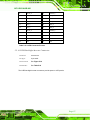
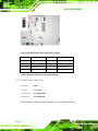
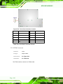
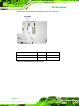
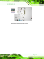
1.5 Dim e n s io n s
The AFL2-W21A/AB-H61 dimensions are shown below.
Figure 1-8: AFL2-W21A/AB-H61 Dimensions (mm)
P a g e 12
AFL2-W21A/AB-H61
Chapter
2
2 LED Lig h t Ba r (Op tio n a l)
P a g e 13
AFL2-W21A/AB-H61
2.1 Ove rvie w
To notify field staffs in an efficient way to increase productivity, the AFL2-W21A-H61
integrates LED dash light system on the side frame. With the provided API software and
LED simulator software, users can customize their notification according to their needs
through a quick and easy user interface. The customized functions include light scripts,
programmable colors, light duration, flash rates and light patterns.
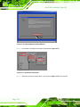
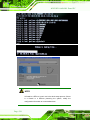
2.2 iEi LED Lig h t Ba r Dis p la y S im u la to r
To configure the LED light bars by iEi LED Light Bar Display Simulator, please follow the
steps below:
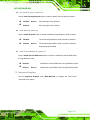
S te p 1:
Make sure LED Bar driver is properly installed. See Section 8.10.
S te p 2:
Double click the AFL2 Series LED Light Bar Simulator setup file.
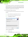
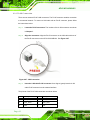
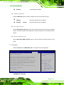
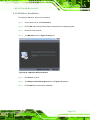
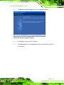
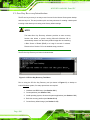
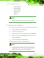
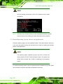
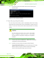
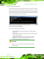
S te p 3:
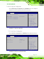
The Setup Wizard starts (Figure 2-1).
Figure 2-1: The Setup Wizard Starts
S te p 4:
Click Next to continue.
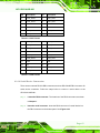
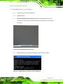
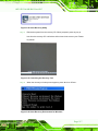
S te p 5:
The Select Installation Folder screen in Figure 2-2 appears.
P a g e 14
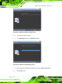
AFL2-W21A/AB-H61
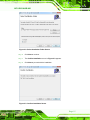
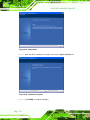
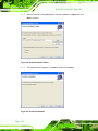
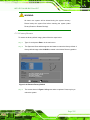
Figure 2-2: Select Installation Folder Screen
S te p 6:
Click Next to continue.
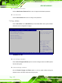
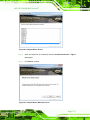
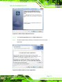
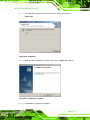
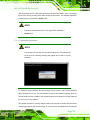
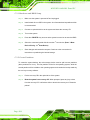
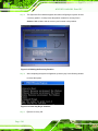
S te p 7:
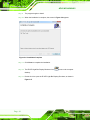
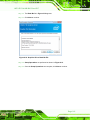
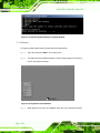
The Confirm Installation screen in Figure 2-3 appears.
S te p 8:
Click Next to proceed with the installation.
Figure 2-3: Confirm Installation Screen
P a g e 15
AFL2-W21A/AB-H61
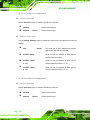
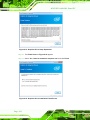
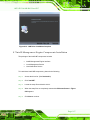
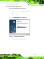
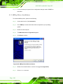
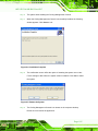
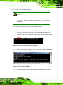
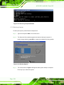
S te p 9:
The program begins to install.
S te p 10: When the installation is complete, the screen in Figure 2-4 appears.
Figure 2-4: Installation Complete
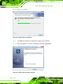
S te p 11: Click Close to complete the installation.
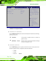
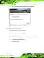
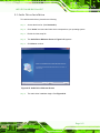
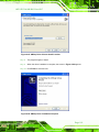
S te p 12: The iEi LED Light Bar Display Simulator icon
shows on the computer
desktop.
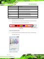
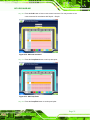
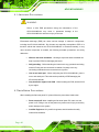
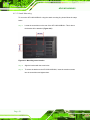
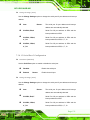
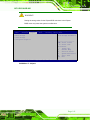
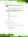
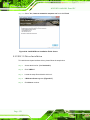
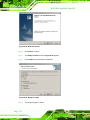
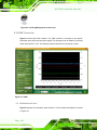
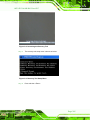
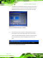
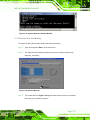
S te p 13: Double click it to open the iEi LED Light Bar Display Simulator, as shown in
Figure 2-5.
P a g e 16
AFL2-W21A/AB-H61
.
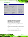
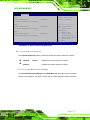
Figure 2-5: iEi LED Light Bar Display Simulator
The descriptions of iEi LED Light Bar Display Simulator are listed below.
Fu n c tio n
De s c rip tio n
New
Clear all current commands
Load
Load the configuration file ( *.cld )
Save
Save all current commands
Run
Start to simulate the LED display
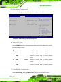
Add
Add a new command
Insert
Insert a command
Copy
Copy a command
Delete
Delete a command
UP
Move the command up
Down
Move the command down
Loop Start
Set loop start point
P a g e 17
AFL2-W21A/AB-H61
Fu n c tio n
De s c rip tio n
Loop End
Set Loop end point
ALL
Select all the LED simulation buttons
TOP
Select the top LED simulation buttons
LEFT
Select the left LED simulation buttons
RIGHT
Select the right LED simulation buttons
1~50
LED simulation buttons
Table 2-1: LED Simulator Software Description
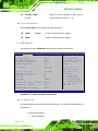
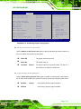
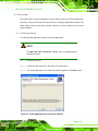
S te p 14: Select the color. The color setting area includes basic color and user defined
color. Click the basic color to select the desired color.
Basic Color
User Defined Color
Figure 2-6: Color Setting Area
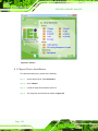
S te p 15: Or you can double click the user defined color to open the color palette and
select the desired color.
Figure 2-7: Color Palette
P a g e 18
AFL2-W21A/AB-H61
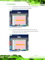
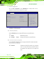
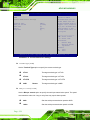
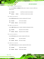
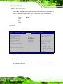
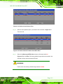
S te p 16: After setting the color, click LED simulation button and the color of selected LED
simulation button will automatically change. See Figure 2-8.
Figure 2-8: Simulate the LED Light
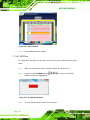
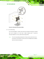
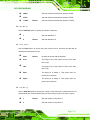
S te p 17: If you want to set all the left LED simulation buttons for a certain color at the
same time, click the “LEFT" button. Setting the right LED simulation buttons and
top LED simulation buttons are the same way.
Figure 2-9: Set the Left LEDs
P a g e 19
AFL2-W21A/AB-H61
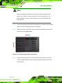
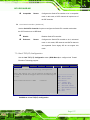
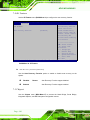
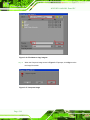
S te p 18: If you want to set all the LED simulation buttons for a certain color at the same
time, click the “ALL" button.
Figure 2-10: Set All the LEDs
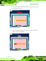
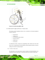
S te p 19: Enter the light duration. Please note that the unit is second, enter a number
between 1 and 20. See Figure 2-11.
Figure 2-11: Light Duration
P a g e 20
AFL2-W21A/AB-H61
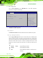
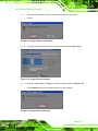
S te p 20: Press the Add button to insert a new control command. You may continue to set
a new command in accordance with Step14 ~ Step19.
Figure 2-12: Add new command
S te p 21: Press the Loop Start button to set loop start point.
Figure 2-13: Add Loop Start
S te p 22: Press the Loop End button to set loop end point.
P a g e 21
AFL2-W21A/AB-H61
Figure 2-14: Add Loop End
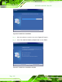
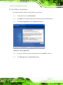
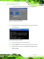
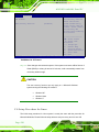
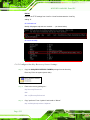
S te p 23: Press the Run button to simulate.
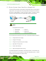
2.3 iEi LED Ru n
To configure the LED light bars through a quick and easy way, please follow the steps
below:
S te p 1:
Make sure the LED Bar driver is properly installed. See Section 8.10.
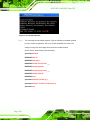
S te p 2:
Double click the LED-RUN.exe icon
software, as shown in Figure 2-15.
Figure 2-15: iEi LED RUN Software
S te p 3:
P a g e 22
The LED light bars start to dash in a preset mode.
to open the LED RUN
AFL2-W21A/AB-H61
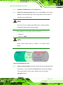
2.4 LED Co n tro l AP I
2.4.1 In tro d u c tio n
This chapter aims to explain how to use LED Light Bar Control API, and support API
version is V1.0.0.7. Due LED Light Bar driver only has x86 version, this API could be used
in the Windows 2000/XP(x86)/2003/7(x86) environments.
2.4.1.1 P ro g ra m m in g La n g ua g e S u p p o rt
The iEi LED Light Bar Control application provides an interface to driver with:
Microsoft Visual C/C++
Microsoft Visual Basic
Other programming systems that can access functions into DLL's
2.4.1.2 Ap p lic a tio n Co n te n t
The iEi LED Light Bar Control application includes the following files:
IBS_LEDCTRL.dll
IBS_LEDCTRL.lib
IBS_LEDCTRL.h
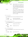
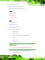
2.4.2 LED Co n tro l AP I Fu n c tio n s
2.4.2.1 LIGHTBAR_Drive rIn it
Syntax:
PACSM_LIGHTBAR_CTRL STD_HANDLE LIGHTBAR_DriverInit(void)
Parameters:
NONE
Return value:
Return a Handle from LED driver.
Remarks:
Call this function to initial and start the LED Driver and return a Handle from LED
driver.
P a g e 23
AFL2-W21A/AB-H61
2.4.2.2 LIGHTBAR_Drive rUn in it
Syntax:
PACSM_LIGHTBAR_CTRL STD_Void LIGHTBAR_DriverUninit(HANDLE hDev)
Parameters:
hDev [IN] – Handle be released.
Return value:
True if success.
Remarks:
Call this function to stop and uninitialized the LED Driver and to release resource of
Handle.
2.4.2.3 LIGHTBAR_De vic e In it
Syntax:
PACSM_LIGHTBAR_CTRL STD_BOOLEN LIGHTBAR_DeviceInit(HANDLE hDev)
Parameters:
hDev [IN] – Input Handle.
Return value:
True if success.
Remarks:
Call this function to initial the LED IC.
2.4.2.4 LIGHTBAR_De vic e Clo s e
Syntax:
PACSM_LIGHTBAR_CTRL STD_BOOLEN LIGHTBAR_DeviceClose(HANDLE hDev)
Parameters:
hDev [IN] – Input Handle.
Return value:
True if success.
Remarks:
Call this function to turn off LED IC.
P a g e 24
AFL2-W21A/AB-H61
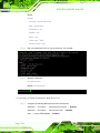
2.4.2.5 LIGHTBAR_Brig h tn e s s _S in g le
Syntax:
PACSM_LIGHTBAR_CTRL STD_BOOLEN LIGHTBAR_Brightness_Single(
HANDLE hDev,
PLED_COLOR_INFO Brightness_Step,
int INFO_Size)
Parameters:
hDev [IN] – Input Handle.
Brightness_Step [IN] –Point to structures buffers to write. (see Section 2.4.3)
INFO_Size [IN] – describe the data structure array size.
Return value:
True if success.
Remarks:
Write data to LED IC on I2C bus via drivers. This function creates data structures
include the target LED IC address and Brightness information to send to LED IC via
LED Driver.
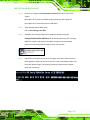
2.4.2.6 LIGHTBAR_BLNK_S e ttin g s
Syntax:
PACSM_LIGHTBAR_CTRL STD_BOOLEN LIGHTBAR_BLNK_Settings(
HANDLE hDev,
PLED_BLNK_SET LED_Blinking_Set)
Parameters:
hDev [IN] – Input Handle.
LED_Blinking_Set [IN] –Point to structures buffers to write. (see Section 2.4.3)
Return value:
True if success.
Remarks:
This function is used to set LED IC Blinking modes via drivers.
P a g e 25
AFL2-W21A/AB-H61
2.4.2.7 LIGHTBAR_BLNK_Typ e
Syntax:
PACSM_LIGHTBAR_CTRL STD_BOOLEN LIGHTBAR_BLNK_Type(
HANDLE hDev,
PLED_BLNK_TYPE Blinking_Type)
Parameters:
hDev [IN] – Input Handle.
Brightness_Step [IN] –Point to structures buffers to write. (see Section 2.4.3)
Return value:
True if success.
Remarks:
This function is used to turn on/off LED IC blinking control via drivers.
2.4.2.8 LIGHTBAR_LED_Mo d e S e t
Syntax:
PACSM_LIGHTBAR_CTRL STD_BOOLEN LIGHTBAR_LED_ModeSet (
HANDLE hDev,
PLED_MODE_SETTINGS LED_Mode_Settings)
Parameters:
hDev [IN] – Input Handle.
LED_Mode_Settings [IN] –Point to structures buffers to write. (see Section 2.4.3)
Return value:
True if success.
Remarks:
This function is used to set each LED operation mode on LED IC via drivers.
P a g e 26
AFL2-W21A/AB-H61
2.4.3 Stru c tu re s
2.4.3.1 _LED_COLOR_INFO
Syntax:
typedef struct _LED_COLOR_INFO{
LED_INFO LED_Info;
int R_LEVEL;
int G_LEVEL;
int B_LEVEL;
}LED_COLOR_INFO, *PLED_COLOR_INFO;
Parameters:
R_LEVEL、G_LEVEL、B_LEVEL [int] - Store the Brightness Level information for
R, G and B LED. The brightness level was from 0 to 7.
LED_Info [structure] - The LED IC address was stored in Main_Addr on the I2c
bus, and LED List
number are stored in R_LN、G_LN and B_LN parameters:
typedef struct _LED_INFO {
UCHAR
Main_Addr;
//Main address
UCHAR
R_LN;
//Red list number
UCHAR
G_LN;
//Green list number
UCHAR
B_LN;
//Blue list number
} LED_INFO, *PLED_INFO;
Remarks:
This structure has included essential information to set LED IC.
2.4.3.2 _LED_BLNK_S ET
Syntax:
typedef struct _LED_BLNK_SET{
UCHAR
Main_Addr;
//Main address
BYTE
BLNK_DutCyc;
//Duty Cycle
BYTE
BLNK_Freq;
//Blinking Frequency
}LED_BLNK_SET, *PLED_BLNK_SET;
Parameters:
Main_Addr [UCHAR] - IC Address on I2C bus.
BLNK_DutCyc [BYTE] - Duty Cycle of LED blinking. Duty cycle = (0
~ 255)/256 = x%。
BLNK_Freq [BYTE] -Frequency of LED blinking. 0x00 = (41ms,
P a g e 27
AFL2-W21A/AB-H61
frequency 24Hz),0xFF = (10.73s),Frequency = [(0~255) + 1]/24=
x(second),Ex:300ms = (7 + 1) / 24 ≒ 0.333s。
Remarks:
This structure has used to store the blinking duty cycle and frequency of LED IC.
Please attention one LED IC only has one duty cycle and frequency to be group
used, It means all LED has the same blink mode on a LED IC.
2.4.3.3 _LED_BLNK_S ET
Syntax:
typedef struct _LED_BLNK_TYPE{
UCHAR
Main_Addr; //Main address
int
BLNK_TYPE;
}LED_BLNK_TYPE, *PLED_BLNK_TYPE;
Parameters:
Main_Addr [UCHAR] – IC Address on I2C bus.
BLNK_Type [int] - Turn on/off blinking circuit on the LED IC. Defined
by:
Remarks:
P a g e 28
#define
LED_BLNK_ON
0
#define
LED_BLNK_OFF
1
This structure has used to turn on/off blinking circuit on the LED IC.
AFL2-W21A/AB-H61
2.4.3.4 _LED_MODE_S ETTINGS
Syntax:
typedef struct _LED_MODE_SETTINGS{
UCHAR
Main_Addr; //Main address
int
LED_00;
int
LED_01;
int
LED_02;
int
LED_03;
int
LED_04;
int
LED_05;
int
LED_06;
int
LED_07;
int
LED_08;
int
LED_09;
int
LED_10;
int
LED_11;
int
LED_12;
int
LED_13;
int
LED_14;
}LED_MODE_SETTINGS, *PLED_MODE_SETTINGS;
Parameters:
Main_Addr [UCHAR] – IC Address on I2C bus.
LED_00 ~ LED_15: Each LED operation mode, defined by:
Remarks:
#define
LED_DispMode_OFF
0
//Turn OFF LED.
#define
LED_DispMode_Gen
1
//General Mode
#define
LED_DispMode_BLNK
2
//Blinking Mode
This structure can decision operation mode for each LED.
2.4.4 P ro g ra m m in g Exa m ple
2.4.4.1 Tu rn o n LED - s in g le
{
//Define Data structure
PLED_PWM_INFO LEDCOLOR = (PLED_PWM_INFO)malloc(sizeof(LED_PWM_INFO));
P a g e 29
AFL2-W21A/AB-H61
HANDLE hSMB_Dev = LIGHTBAR_DriverInit();//Init SMBAPI driver and get device Handle.
LIGHTBAR_DeviceInit(hSMB_Dev);//Init Target device
//Set LED level information.
LEDCOLOR.R_LEVEL = 7;
LEDCOLOR.G_LEVEL = 7;
LEDCOLOR.B_LEVEL = 7;
//Set LED Address
LEDCOLOR.LED_Info.Main_Addr = 0xC0;
LEDCOLOR.LED_Info.R_LN = 0x00;
LEDCOLOR.LED_Info.G_LN = 0x01;
LEDCOLOR.LED_Info.B_LN = 0x02;
If(LIGHTBAR_Brightness_Single(hSMB_Dev, LEDCOLOR, 1) == False){
//Error message
}
LIGHTBAR_DeviceClose(hSMB_Dev);
//Close Device.
LIGHTBAR_DriverUninit(hSMB_Dev);
//Close Driver Handle
delete LEDCOLOR;
}
2.4.4.2 Tu rn o n LED - m u ltip le
{
//Define Data structure
PLED_PWM_INFO LEDCOLOR = (PLED_PWM_INFO)malloc(sizeof(LED_PWM_INFO) * 4);
HANDLE hSMB_Dev = LIGHTBAR_DriverInit();//Init SMBAPI driver and get device Handle.
LIGHTBAR_DeviceInit(hSMB_Dev);//Init Target device
LEDCOLOR [0].LED_Info.Main_Addr = 0xD0;
LEDCOLOR [0].LED_Info.R_LN = 0x02;
LEDCOLOR [0].LED_Info.G_LN = 0x03;
LEDCOLOR [0].LED_Info.B_LN = 0x04;
LEDCOLOR [0].R_LEVEL = 7;
P a g e 30
AFL2-W21A/AB-H61
LEDCOLOR [0].G_LEVEL = 7;
LEDCOLOR [0].B_LEVEL = 7;
LEDCOLOR [1].LED_Info.Main_Addr = 0xD0;
LEDCOLOR [1].LED_Info.R_LN = 0x05;
LEDCOLOR [1].LED_Info.G_LN = 0x06;
LEDCOLOR [1].LED_Info.B_LN = 0x07;
LEDCOLOR [1].R_LEVEL = 7;
LEDCOLOR [1].G_LEVEL = 7;
LEDCOLOR [1].B_LEVEL = 7;
LEDCOLOR [2].LED_Info.Main_Addr = 0xD0;
LEDCOLOR [2].LED_Info.R_LN = 0x08;
LEDCOLOR [2].LED_Info.G_LN = 0x09;
LEDCOLOR [2].LED_Info.B_LN = 0x0a;
LEDCOLOR [2].R_LEVEL = 7;
LEDCOLOR [2].G_LEVEL = 7;
LEDCOLOR [2].B_LEVEL = 7;
LEDCOLOR [3].LED_Info.Main_Addr = 0xD0;
LEDCOLOR [3].LED_Info.R_LN = 0x0b;
LEDCOLOR [3].LED_Info.G_LN = 0x0c;
LEDCOLOR [3].LED_Info.B_LN = 0x0d;
LEDCOLOR [3].R_LEVEL = 7;
LEDCOLOR [3].G_LEVEL = 7;
LEDCOLOR [3].B_LEVEL = 7;
LEDCOLOR [4].LED_Info.Main_Addr = 0xD0;
LEDCOLOR [4].LED_Info.R_LN = 0x0e;
LEDCOLOR [4].LED_Info.G_LN = 0x0f;
LEDCOLOR [4].LED_Info.B_LN = 0x10;
LEDCOLOR [4].R_LEVEL = 7;
LEDCOLOR [4].G_LEVEL = 7;
LEDCOLOR [4].B_LEVEL = 7;
If(LIGHTBAR_Brightness_Single(hSMB_Dev, LEDCOLOR, 5) == False){
//Error message
}
P a g e 31
AFL2-W21A/AB-H61
LIGHTBAR_DeviceClose(hSMB_Dev);
//Close Device.
LIGHTBAR_DriverUninit(hSMB_Dev);
//Close Driver Handle
delete LEDCOLOR;
}
2.4.4.3 LED Blin k - 1
{
PLED_MODE_SETTINGS
LED_ModeSet =
(PLED_MODE_SETTINGS)malloc(sizeof(LED_MODE_SETTINGS));
PLED_BLNK_SET
LED_Blinking_Set = (P LED_BLNK_SET)malloc(sizeof(LED_BLNK_SET));
PLED_BLNK_TYPE
LED_Blinking_Type =
(PLED_BLNK_TYPE)malloc(sizeof(LED_BLNK_TYPE));
// Set Structure: Set Broadcast address
LED_ModeSet.Main_Addr = 0xD0;
LED_Blinking_Set.Main_Addr = 0xD0;
LED_Blinking_Type.Main_Addr = 0xD0;
//Set Structure: Set blinking settings.
LED_Blinking_Set.BLNK_Freq = 0x07;
//300ms
LED_Blinking_Set.BLNK_DutCyc = 0x80;
//50:50
//Set Structure: Set each LED operation mode.
LED_ModeSet.LED_00 = LED_DispMode_BLNK;
//R
LED_ModeSet.LED_01 = LED_DispMode_BLNK;
//G
LED_ModeSet.LED_02 = LED_DispMode_BLNK;
//B
LED_ModeSet.LED_03 = LED_DispMode_BLNK;
//R
LED_ModeSet.LED_04 = LED_DispMode_BLNK;
//G
LED_ModeSet.LED_05 = LED_DispMode_BLNK;
//B
LED_ModeSet.LED_06 = LED_DispMode_BLNK;
//R
LED_ModeSet.LED_07 = LED_DispMode_BLNK;
//G
LED_ModeSet.LED_08 = LED_DispMode_BLNK;
//B
LED_ModeSet.LED_09 = LED_DispMode_BLNK;
//R
LED_ModeSet.LED_10 = LED_DispMode_BLNK;
//G
LED_ModeSet.LED_11 = LED_DispMode_BLNK;
//B
LED_ModeSet.LED_12 = LED_DispMode_BLNK;
//R
LED_ModeSet.LED_13 = LED_DispMode_BLNK;
//G
P a g e 32
AFL2-W21A/AB-H61
LED_ModeSet.LED_14 = LED_DispMode_BLNK;
//B
LED_ModeSet.LED_15 = LED_DispMode_BLNK;
//Set Structure: Enable blinking of IC
LED_Blinking_Type.BLNK_TYPE = LED_BLNK_ON;
LIGHTBAR_BLNK_Settings(hSMB_Dev, LED_Blinking_Set);
//Set LED blinking
settings.
LIGHTBAR_LED_ModeSet(hSMB_Dev, LED_ModeSet)
//Set LED Operation
Mode.
LIGHTBAR_BLNK_Type(hSMB_Dev, LED_Blinking_Type);
//Enable LED Blinking.
}
2.4.4.4 LED Blin k - 2
{
PLED_MODE_SETTINGS
LED_ModeSet =
(PLED_MODE_SETTINGS)malloc(sizeof(LED_MODE_SETTINGS));
PLED_BLNK_SET
LED_Blinking_Set = (P LED_BLNK_SET)malloc(sizeof(LED_BLNK_SET));
PLED_BLNK_TYPE
LED_Blinking_Type =
(PLED_BLNK_TYPE)malloc(sizeof(LED_BLNK_TYPE));
// Set Structure: Set Broadcast address
LED_ModeSet.Main_Addr = 0xD0;
LED_Blinking_Set.Main_Addr = 0xD0;
LED_Blinking_Type.Main_Addr = 0xD0;
//Set Structure: Set blinking settings.
LED_Blinking_Set.BLNK_Freq = 0x07;
//300ms
LED_Blinking_Set.BLNK_DutCyc = 0x80;
//50:50
//Set Structure: Set each LED operation mode.
LED_ModeSet.LED_00 = LED_DispMode_Gen;
//R
LED_ModeSet.LED_01 = LED_DispMode_Gen;
//G
LED_ModeSet.LED_02 = LED_DispMode_Gen;
//B
LED_ModeSet.LED_03 = LED_DispMode_BLNK;
//R
LED_ModeSet.LED_04 = LED_DispMode_BLNK;
//G
LED_ModeSet.LED_05 = LED_DispMode_BLNK;
//B
P a g e 33
AFL2-W21A/AB-H61
LED_ModeSet.LED_06 = LED_DispMode_Gen;
//R
LED_ModeSet.LED_07 = LED_DispMode_Gen;
//G
LED_ModeSet.LED_08 = LED_DispMode_Gen;
//B
LED_ModeSet.LED_09 = LED_DispMode_BLNK;
//R
LED_ModeSet.LED_10 = LED_DispMode_BLNK;
//G
LED_ModeSet.LED_11 = LED_DispMode_BLNK;
//B
LED_ModeSet.LED_12 = LED_DispMode_Gen;
//R
LED_ModeSet.LED_13 = LED_DispMode_Gen;
//G
LED_ModeSet.LED_14 = LED_DispMode_Gen;
//B
LED_ModeSet.LED_15 = LED_DispMode_BLNK;
//Set Structure: Enable blinking of IC
LED_Blinking_Type.BLNK_TYPE = LED_BLNK_ON;
LIGHTBAR_BLNK_Settings(hSMB_Dev, LED_Blinking_Set);
//Set LED blinking
settings.
LIGHTBAR_LED_ModeSet(hSMB_Dev, LED_ModeSet)
//Set LED Operation
Mode.
LIGHTBAR_BLNK_Type(hSMB_Dev, LED_Blinking_Type);
}
P a g e 34
//Enable LED Blinking.
AFL2-W21A/AB-H61
Chapter
3
3 Un p a c kin g
P a g e 35
AFL2-W21A/AB-H61
3.1 Un pa c kin g
To unpack the flat bezel panel PC, follow the steps below:
WARNING!
The front side LCD screen has a protective plastic cover stuck to the
screen. Only remove the plastic cover after the flat bezel panel PC has
been properly installed. This ensures the screen is protected during the
installation process.
S te p 1:
Use box cutters, a knife or a sharp pair of scissors that seals the top side of the
external (second) box.
S te p 2:
Open the external (second) box.
S te p 3:
Use box cutters, a knife or a sharp pair of scissors that seals the top side of the
internal (first) box.
S te p 4:
Lift the monitor out of the boxes.
S te p 5:
Remove both polystyrene ends, one from each side.
S te p 6:
Pull the plastic cover off the flat bezel panel PC.
S te p 7:
Make sure all the components listed in the packing list are present. S te p 0:
3.1.1 P a c kin g Lis t
The AFL2-W21A/AB-H61 flat bezel panel PC is shipped with the following components:
Qu a n tity Ite m
S ta n d a rd
1
P a g e 36
AFL2-W21A/AB-H61 panel PC
Im a g e
AFL2-W21A/AB-H61
1
Power adapter
(P/N: 63000-FSP120AAB-RS)
1
Power cord
(P/N: 32702-000401-100-RS)
1
Power transfer cord
(P/N: 32000-089400-RS)
1
Infrared Remote Controller
(P/N: 7Z000-SLPCB005-RS)
1
Pen
(P/N: 43125-0002C0-00-RS)
4
M3 screw pack
(P/N: 44013-030041-RS)
4
M4 screw pack
(P/N: 44033-040061-RS)
1
Utility CD
1
One Key Recovery CD
Op tio n a l
Wall mounting kit
(P/N: AFLWK-19/AFLWK-19B)
P a g e 37
AFL2-W21A/AB-H61
Arm
(P/N: STAND-A21)
Stand
(P/N: STAND-A21-R10)
Hybrid Card Reader (MSI only for AFL2-W21AB series)
(P/N: AFL2P-21AMSI-U-R10)
Magnetic Stripe Reader
(P/N: AFL2P-21AMSR-U-R10)
Slim DVD Burner Installation Kit (Including SATA Cable)
Bluetooth Module Kit
(P/N: AFL2-BT-KIT01-R11)
Trusted Platform Module (TPM)
(P/N: TPM-IN01-R11)
EM RFID Reader
(P/N: AFL2-EM-RFID-KIT03-R10)
Mifare RFID Reader
(P/N: AFL2-MF-RFID-KIT04-R10)
If any of these items are missing or damaged, contact the distributor or sales
representative immediately.
P a g e 38
AFL2-W21A/AB-H61
Chapter
4
4
In s ta lla tio n
P a g e 39
AFL2-W21A/AB-H61
4.1 An ti-s ta tic P re c a u tio n s
WARNING:
Failure to take ESD precautions during the maintenance of the
AFL2-W21A/AB-H61 may result in permanent damage to the
AFL2-W21A/AB-H61 and severe injury to the user.
Electrostatic discharge (ESD) can cause serious damage to electronic components,
including the AFL2-W21A/AB-H61. Dry climates are especially susceptible to ESD. It is
therefore critical that whenever the AFL2-W21A/AB-H61 is accessed internally, or any
other electrical component is handled, the following anti-static precautions are strictly
adhered to.
Wear an anti-static wristband: - Wearing a simple anti-static wristband can
help to prevent ESD from damaging the board.
Self-grounding: - Before handling the board touch any grounded conducting
material. During the time the board is handled, frequently touch any
conducting materials that are connected to the ground.
Use an anti-static pad: - When configuring the AFL2-W21A/AB-H61, place it
on an antic-static pad. This reduces the possibility of ESD damaging the
AFL2-W21A/AB-H61.
Only handle the edges of the PCB: - When handling the PCB, hold the PCB
by the edges.
4.2 In s ta lla tio n P re c a u tio n s
When installing the flat bezel panel PC, please follow the precautions listed below:
Power turned off: When installing the flat bezel panel PC, make sure the
power is off. Failing to turn off the power may cause severe injury to the body
and/or damage to the system.
Certified Engineers: Only certified engineers should install and modify
onboard functionalities.
P a g e 40
AFL2-W21A/AB-H61
Anti-static Discharge: If a user open the rear panel of the flat bezel panel PC,
to configure the jumpers or plug in added peripheral devices, ground
themselves first and wear and anti-static wristband.
4.3 In s ta lla tio n a n d Co n fig u ra tio n Ste ps
The following installation steps must be followed.
S te p 1:
Unpack the flat bezel panel PC.
S te p 2:
Install the HDD.
S te p 3:
Install the K-type temperature sensor.
S te p 4:
Install the RFID reader (optional).
S te p 5:
Install the CD-ROM (optional).
S te p 6:
Configure the system.
S te p 7:
Connect peripheral devices to the flat bezel panel PC.
S te p 8:
Mount the flat bezel panel PC. S te p 0:
4.4 HDD In s ta lla tio n
WARNING:
Over-tightening back cover screws will crack the plastic frame.
Maximum torque for cover screws is 5 kg-cm (0.36 lb-ft/0.49 Nm).
To install the HDD into the AFL2-W21A/AB-H61, please follow the steps below:
S te p 1:
Remove two (2) retention screws from the HDD cover (Figure 4-1).
P a g e 41
AFL2-W21A/AB-H61
Figure 4-1: HDD Cover Retention Screws
S te p 2:
Remove the HDD cover from the device.
S te p 3:
Loosen the captive screw to release the HDD bracket from the chassis (Figure
4-2).
Figure 4-2: HDD Bracket Screw
P a g e 42
AFL2-W21A/AB-H61
S te p 4:
Slide the HDD bracket out of the device as shown (Figure 4-3).
Figure 4-3: Removing the HDD Bracket
S te p 5:
Insert an HDD into the bracket as shown (Figure 4-4).
Figure 4-4: Inserting the HDD
S te p 6:
Secure the HDD to the bracket using four (4) retention screws (Figure 4-5).
P a g e 43
AFL2-W21A/AB-H61
Figure 4-5: Securing the HDD
S te p 7:
Slide the HDD module back into the device.
S te p 8:
Tighten the captive screw.
S te p 9:
Replace the HDD cover and secure it using two (2) retention screws.
S te p 0:
4.5 K-Typ e Te m p e ra tu re S e n s o r In s ta lla tio n
The AFL2-W21A/AB-H61 has a K-type connector on the external peripheral interface
panel. The K-type connector is connected to a K-type temperature sensor cable. The
K-type temperature sensor cable can be found in the packing list. To connect a K-type
temperature sensor cable to the AFL2-W21A/AB-H61, please follow the instructions
below.
S te p 1:
Locate the K-type connector. The location is shown in Chapter 1.
S te p 2:
Align the connector. Align the K-type temperature sensor cable with the K-type
connector on the AFL2-W21A/AB-H61 . Make sure the orientation of the
connector is correct.
P a g e 44
AFL2-W21A/AB-H61
Figure 4-6: Insert the K-type Temperature Sensor Cable
S te p 3:
Insert the K-type connector. Gently insert the K-type temperature sensor cable.
The connector should engage with a gentle push.
4.6 RFID Re a d e r (Op tio n a l)
The AFL2-W21A/AB-H61 series (selected models only) supports RFID reader function.
The RFID reader is located at the bottom of the screen. An optional Mifare 13.56 MHz or
EM 125 KHz RFID reader can be integrated in the system. All the data on the RFID tag
can be easily retrieved or updated through the reader to secure the data transmission
process and increase efficiency for certain identity group.
To install the RFID reader, follow the steps below.
S te p 1:
Connect the RFID USB cable to the USB connector on the RFID reader module.
(Figure 4-7)
Figure 4-7: Connect the RFID USB cable
P a g e 45
AFL2-W21A/AB-H61
S te p 4:
Connect the RFID connector of the RFID USB cable to the RFID connector on
the motherboard (RFID_USB1).
S te p 5:
Attach the sticker of the RFID module to the bottom of the panel.
Figure 4-8: Install the RFID module
S te p 6:
Secure the RFID module to the motherboard using two retention screws on
either side.
S te p 7:
Use the RFID reader to read a RFID card.
4.7 DVD-ROM In s ta lla tio n (Op tio n a l)
To install a DVD-ROM, please follow the steps below.
S te p 1:
Remove the DVD-ROM bracket from the AFL2-W21A/AB-H61. (Figure 4-9).
Figure 4-9: DVD-ROM Bracket
P a g e 46
AFL2-W21A/AB-H61
S te p 2:
Loosen the captive screw to release the HDD bracket from the system and slide
the HDD bracket out of the system as shown.
Figure 4-10: Remove the HDD Bracket
S te p 3:
Insert the DVD-ROM to the DVD-ROM bay and secure the DVD-ROM to the
DVD-ROM bracket using four screws (two screws on each side). (Figure 4-11)
Figure 4-11: Secure the DVD-ROM
S te p 4:
Attach the SATA cable to the DVD-ROM and fasten the SATA cable screws.
Connect the SATA cable and power cable to the connectors on the motherboard.
(Figure 4-12).
P a g e 47
AFL2-W21A/AB-H61
Figure 4-12: DVD-ROM Installation
4.8 AT/ATX Mo d e S e le c tio n
AT or ATX power mode can be used on the AFL2-W21A/AB-H61. The selection is made
through an AT/ATX switch located on the bottom panel (Figure 4-13). To select AT mode
or ATX mode, follow the steps below.
S te p 1:
Locate the AT/ATX switch on the bottom panel (Figure 4-13).
Figure 4-13: AT/ATX Switch Location
S te p 2:
Adjust the AT/ATX switch.
4.8.1 AT P owe r Mo d e
With the AT mode selected, the power is controlled by a central power unit rather than a
power switch. The AFL2-W21A/AB-H61 panel PC turns on automatically when the power
is connected. The AT mode benefits a production line to control multiple panel PCs from a
central management center and other applications including:
P a g e 48
AFL2-W21A/AB-H61
ATM
Self-service kiosk
Plant environment monitoring system
Factory automation platform
Manufacturing shop flow
4.8.2 ATX P owe r Mo d e
With the ATX mode selected, the AFL2-W21A/AB-H61 panel PC goes in a standby mode
when it is turned off. The panel PC can be easily turned on via network or a power switch
in standby mode. Remote power control is perfect for advertising applications since the
broadcasting time for each panel PC can be set individually and controlled remotely. Other
possible application includes
Security surveillance
Point-of-Sale (POS)
Advertising terminal
4.9 Cle a r CMOS
If the AFL2-W21A/AB-H61 fails to boot due to improper BIOS settings, the clear CMOS
switch clears the CMOS data and resets the system BIOS information. To do this, adjust
the clear CMOS switch to clear CMOS mode for a few seconds then reinstall the clear
CMOS switch back to keep CMOS mode.
S te p 1:
Locate the clear CMOS switch on the bottom panel (Figure 4-14).
Figure 4-14: Clear CMOS Switch Location
S te p 2:
Adjust the clear CMOS switch. S te p 0:
P a g e 49
AFL2-W21A/AB-H61
4.10 Re s e t th e S ys te m
The reset button enables user to reboot the system when the system is turned on. To
reboot the system, follow the steps below.
S te p 1:
Locate the reset button on the bottom panel (Figure 4-15).
Figure 4-15: Reset Button Location
S te p 2:
Press the reset button. S te p 0:
4.11 P owe rin g On th e S ys te m
To power on the system, follow the steps below:
S te p 1:
Locate the Function and Brightness Up function keys. See Section 1.2.1.1.
S te p 2:
Hold down the Function and Brightness Up buttons for three seconds to power
on the system. S te p 0:
4.12 P owe rin g Off th e S ys te m
To power off the system, follow the steps below:
S te p 1:
Locate the Function and Brightness Up function keys. See Section 1.2.1.1.
S te p 2:
Hold down the Function and Brightness Up buttons for six seconds to power off
the system. S te p 0:
P a g e 50
AFL2-W21A/AB-H61
4.13 Mo u n tin g th e S ys te m
WARNING!
When mounting the flat bezel panel PC onto an arm, onto the wall or onto a
panel, it is better to have more than one person to help with the installation
to make sure the panel PC does not fall down and get damaged.
The four methods of mounting the AFL2-W21A/AB-H61 are listed below.
Wall mounting
Panel mounting
Stand mounting
Arm mounting
The four mounting methods are described below.
4.13.1 Wa ll Mo u n tin g
To mount the flat bezel panel PC onto the wall, please follow the steps below.
S te p 1:
Select the location on the wall for the wall-mounting bracket.
S te p 2:
Carefully mark the locations of the four screw holes in the bracket on the wall.
S te p 3:
Drill four pilot holes at the marked locations on the wall for the bracket retention
screws.
S te p 4:
Align the wall-mounting bracket screw holes with the pilot holes.
S te p 5:
Secure the mounting-bracket to the wall by inserting the retention screws into
the four pilot holes and tightening them (Figure 4-16).
P a g e 51
AFL2-W21A/AB-H61
Figure 4-16: Wall-mounting Bracket
S te p 8:
Insert the four monitor mounting screws provided in the wall mount kit into the
four screw holes on the real panel of the flat bezel panel PC and tighten until the
screw shank is secured against the rear panel (Figure 4-17).
WARNING:
Please use the M4 screws provided in the wall mount kit for the rear panel.
If the screw is missing, the thread depth of the replacement screw should
be not more than 4 mm.
P a g e 52
AFL2-W21A/AB-H61
S te p 9:
Align the mounting screws on the monitor rear panel with the mounting holes on
the bracket.
S te p 10: Carefully insert the screws through the holes and gently pull the monitor
downwards until the monitor rests securely in the slotted holes (Figure 4-17).
Ensure that all four of the mounting screws fit snugly into their respective slotted
holes.
NOTE:
In the diagram below the bracket is already installed on the wall.
Figure 4-17: Chassis Support Screws
S te p 11: Secure the panel PC by fastening the retention screw of the wall-mounting
bracket. (Figure 4-18). S te p 0:
P a g e 53
AFL2-W21A/AB-H61
Figure 4-18: Secure the Panel PC
4.13.2 P a n e l Mo u n tin g
To mount the AFL2-W21A/AB-H61 flat bezel panel PC into a panel, please follow the
steps below.
S te p 1:
Select the position on the panel to mount the flat bezel panel PC.
S te p 2:
Cut out a section corresponding to the size shown below. The size must be
smaller than the outer edge.
Figure 4-19: Cutout Dimensions
P a g e 54
AFL2-W21A/AB-H61
S te p 3:
Slide the flat bezel panel PC through the hole until the frame is flush against the
panel.
S te p 4:
Align the panel mounting bracket screw holes with the VESA mounting holes on
the rear of the panel PC.
S te p 5:
Secure the two panel mounting brackets to the rear of the panel PC by inserting
the four retention screws into the VESA mounting holes (Figure 4-20 ).
S te p 6:
Insert the panel mounting clamps into the holes of the panel mounting brackets
(Figure 4-20 ). There are a total of 4 panel mounting clamps for
AFL2-W21A/AB-H61.
S te p 7:
Tighten the screws that pass through the panel mounting clamps until the plastic
caps at the front of all the screws are firmly secured to the panel.
S te p 8:
Install the covers into the panel mounting bracket. Each mounting bracket
includes two side covers and one top cover (Figure 4-20 ).
Figure 4-20: Tighten the Panel Mounting Clamp Screws
P a g e 55
AFL2-W21A/AB-H61
4.13.3 Sta n d Mo u n tin g
To mount the AFL2-W21A/AB-H61 using the stand mounting kit, please follow the steps
below.
S te p 1:
Locate the screw holes on the rear of the AFL2-W21A/AB-H61. This is where
the bracket will be attached. (Figure 4-21)
Figure 4-21: Mounting screw location
S te p 2:
Align the bracket with the screw holes.
S te p 3:
To secure the bracket to the AFL2-W21A/AB-H61, insert the retention screws
into the screw holes and tighten them.
P a g e 56
AFL2-W21A/AB-H61
Figure 4-22: Stand Mounting (Stand-A/Bxx)
4.13.4 Arm Mo u n tin g
The AFL2-W21A/AB-H61 is VESA (Video Electronics Standards Association) compliant
and can be mounted on an arm with a 100mm interface pad. To mount the
AFL2-W21A/AB-H61 on an arm, please follow the steps below.
S te p 1:
The arm is a separately purchased item. Please correctly mount the arm onto
the surface it uses as a base. To do this, refer to the installation documentation
that came with the mounting arm.
P a g e 57
AFL2-W21A/AB-H61
NOTE:
When purchasing the arm please ensure that it is VESA compliant and that
the arm has a 100mm x 100mm interface pad. If the mounting arm is not
VESA compliant it cannot be used to support the AFL2-W21A/AB-H61 flat
bezel panel PC.
S te p 2:
Once the mounting arm has been firmly attached to the surface, lift the flat bezel
panel PC onto the interface pad of the mounting arm.
S te p 3:
Align the retention screw holes on the mounting arm interface with those in the
flat bezel panel PC (Figure 4-23).
Figure 4-23: Arm Mounting Retention Screw Holes
S te p 4:
Secure the flat bezel panel PC to the interface pad by inserting four retention
screws through the bottom of the mounting arm interface pad and into the flat
bezel panel PC.
P a g e 58
AFL2-W21A/AB-H61
Figure 4-24: Arm Mounting (ARM-11-RS)
4.14 Exte rn a l P e rip h e ra l De vic e Co n n e c tio n
The following external peripheral devices can be connected to the external peripheral
interface connectors.
Audio devices
HDMI devices
RJ-45 Ethernet cable connector
Serial port devices
USB devices
VGA monitor
To install these devices, connect the corresponding cable connector from the actual
device to the corresponding AFL2-W21A/AB-H61 external peripheral interface connector
making sure the pins are properly aligned.
4.14.1 Au d io Co n n e c tio n
The audio jacks on the external audio connector enable the AFL2-W21A/AB-H61 to be
connected to a stereo sound setup. To install the audio devices, follow the steps below.
P a g e 59
AFL2-W21A/AB-H61
Identify the audio plugs. The plugs on your home theater system or speakers
S te p 1:
may not match the colors on the rear panel. If audio plugs are plugged into the
wrong jacks, sound quality will be very bad.
Plug the audio plugs into the audio jacks. Plug the audio plugs into the audio
S te p 2:
jacks. If the plugs on your speakers are different, an adapter will need to be used
to plug them into the audio jacks.
Line Out port (Lime): Connects to a headphone or a speaker.
Microphone (Pink): Connects to a microphone.
Figure 4-25: Audio Connector
S te p 3:
Check audio clarity. Check that the sound is coming through the right speakers
by adjusting the balance front to rear and left to right.
4.14.2 HDMI De vic e Co n n e c tio n
The HDMI connector transmits a digital signal to compatible HDMI display devices such
as a TV or computer screen. To connect the HDMI cable to the AFL2-W21A/AB-H61,
follow the steps below.
S te p 1:
Locate the HDMI connector. The location is shown in Chapter 1.
S te p 2:
Align the connector. Align the HDMI connector with the HDMI port. Make sure
the orientation of the connector is correct.
P a g e 60
AFL2-W21A/AB-H61
Figure 4-26: HDMI Connection
S te p 3:
Insert the HDMI connector. Gently insert the HDMI connector. The connector
should engage with a gentle push. If the connector does not insert easily, check
again that the connector is aligned correctly, and that the connector is being
inserted with the right way up.
The pinouts of the HDMI connector is shown below.
Pin
Description
Pin
Description
1
HDMI_TMDS_C_DATA2
2
GND
3
HDMI_TMDS_C_DATA2#
4
HDMI_TMDS_C_DATA1
5
GND
6
HDMI_TMDS_C_DATA1#
7
HDMI_TMDS_C_DATA0
8
GND
9
HDMI_TMDS_C_DATA0#
10
HDMI_TMDS_C_CLK
11
GND
12
HDMI_TMDS_C_CLK#
13
NC
14
NC
15
HDMI_DDC_SCLK
16
HDMI_DDC_SDATA
17
GND
18
+5V_HDMI
19
HDMI_HPD
Table 4-1: HDMI Pinouts
P a g e 61
AFL2-W21A/AB-H61
4.14.3 LAN Co n n e c tio n
There are two external RJ-45 LAN connectors. The RJ-45 connector enables connection
to an external network. To connect a LAN cable with an RJ-45 connector, please follow
the instructions below.
S te p 1:
Locate the RJ-45 connectors. The locations of the LAN connectors are shown
in Chapter 1.
S te p 2:
Align the connectors. Align the RJ-45 connector on the LAN cable with one of
the RJ-45 connectors on the AFL2-W21A/AB-H61. See Figure 4-27.
Figure 4-27: LAN Connection
S te p 3:
Insert the LAN cable RJ-45 connector. Once aligned, gently insert the LAN
cable RJ-45 connector into the external interface.
The pinouts of the RJ-45 LAN connectors are shown below.
Pin
Description
Pin
Description
1
LAN1_MDI0+
2
LAN1_MDI0-
3
LAN1_MDI1+
4
LAN1_MDI1-
5
GND
6
GND
P a g e 62
AFL2-W21A/AB-H61
Pin
Description
Pin
Description
7
LAN1_MDI2+
8
LAN1_MDI2-
9
LAN1_MDI3+
10
LAN1_MDI3-
11
GND
12
GND
13
NC
14
NC
L1
LAN1_LINK100
L2
LAN1_LINK1000
L3
LAN1_ACT-1
L4
POWER
Table 4-2: LAN1 Pinouts
Pin
Description
Pin
Description
1
LAN2_MDI0+
2
LAN2_MDI0-
3
LAN2_MDI1+
4
LAN2_MDI1-
5
GND
6
GND
7
LAN12_MDI2+
8
LAN2_MDI2-
9
LAN2_MDI3+
10
LAN2_MDI3-
11
GND
12
GND
13
NC
14
NC
L1
LAN12_LINK100
L2
LAN2_LINK1000
L3
LAN2_ACT-1
L4
POWER
Table 4-3: LAN2 Pinouts
4.14.4 S e ria l De vic e Co n n e c tio n
There are two external RS-232 DB-9 connectors and one RS-422/485 DB-9 connector for
serial device connection. Follow the steps below to connect a serial device to the
AFL2-W21A/AB-H61.
S te p 1:
Locate the DB-9 connector. The locations of the DB-9 connectors are shown
in Chapter 1.
S te p 2:
Insert the serial connector. Insert the DB-9 connector of a serial device into
the DB-9 connector on the bottom panel. See Figure 4-28.
P a g e 63
AFL2-W21A/AB-H61
Figure 4-28: DB-9 Serial Port Connector
S te p 3:
Secure the connector. Secure the serial device connector to the external
interface by tightening the two retention screws on either side of the connector.
The pinouts of the RS-232 serial ports are shown below.
Pin
Description
Pin
Description
1
NDCD1
2
NSIN1
3
NSOUT1
4
NDTR1
5
GND
6
NDSR1
7
NRTS1
8
NCTS1
9
XRI1
10
NDCD2
11
NSIN2
12
NSOUT2
13
NDTR2
14
GND
15
NDSR2
16
NRTS2
17
NCTS2
18
XRI2
Table 4-4: RS-232 Serial Ports Pinouts (COM1, COM2)
P a g e 64
Step 0:
AFL2-W21A/AB-H61
The pinouts of the RS-422/485 serial ports are shown below.
Pin
Description
Pin
Description
1
RXD485+
2
RXD485#
3
TXD485+
4
TXD485#
Table 4-5: RS-422/485 Serial Port Pinouts (COM3)
4.14.5 US B De vic e Co n n e c tio n
NOTE:
User must install the USB 3.0 driver before connecting a USB device to
the system or else the system may not recognize the connected
device.
There are three USB 2.0 connectors and two USB 3.0 connectors on the
AFL2-W21A/AB-H61. To connect a USB device, please follow the instructions below.
S te p 1:
Locate the USB connectors. The locations of the USB connectors are shown
in Chapter 1.
S te p 2:
Align the connectors. Align the USB device connector with one of the
connectors on the bottom panel. See Figure 4-29.
P a g e 65
AFL2-W21A/AB-H61
Figure 4-29: USB Device Connection
S te p 3:
Insert the device connector. Once aligned, gently insert the USB device
connector into the onboard connector. S te p 0:
The pinouts of the USB 2.0 connectors are shown below.
Pin
Description
Pin
Description
1
POWER
2
-DATA0
3
+DATA0
4
GND
5
POWER
6
-DATA1
7
+DATA1
8
GND
Table 4-6: USB 2.0 connectors Pinouts (bottom panel)
Pin
Description
Pin
Description
1
POWER
2
-DATA2
3
+DATA2
4
USB20_GND
Table 4-7: USB 2.0 connectors Pinouts (left side panel)
P a g e 66
AFL2-W21A/AB-H61
The pinouts of the USB 3.0 connectors are shown below.
S te p 1:
Pin
Description
Pin
Description
1
USB3_PWR1
2
USB2P0_DM1_L
3
USB2P0_DP1_L
4
GND
5
USB3P0_RXDN1_L
6
USB3P0_RXDP1_L
7
GND
8
USB3P0_TXDN1_C_L
9
USB3P0_TXDP1_C_L
10
USB3_PWR2
11
USB2P0_DM2_L
12
USB2P0_DP2_L
13
GND
14
USB3P0_RXDN2_L
15
USB3P0_RXDP2_L
16
GND
17
USB3P0_TXDN2_C_L
18
USB3P0_TXDP2_C_L
Table 4-8: USB 3.0 connectors Pinouts
4.14.6 VGA Mo n ito r Co n n e c tio n
The AFL2-W21A/AB-H61 has a single female DB-15 connector on the external peripheral
interface panel. The DB-15 connector is connected to a CRT or VGA monitor. To connect
a monitor to the AFL2-W21A/AB-H61, please follow the instructions below.
S te p 1:
Locate the female DB-15 connector. The location of the female DB-15
connector is shown in Chapter 1.
S te p 2:
Align the VGA connector. Align the male DB-15 connector on the VGA screen
cable with the female DB-15 connector on the external peripheral interface.
S te p 3:
Insert the VGA connector. Once the connectors are properly aligned with the
insert the male connector from the VGA screen into the female connector on the
AFL2-W21A/AB-H61. See Figure 4-30.
P a g e 67
AFL2-W21A/AB-H61
Figure 4-30: VGA Connector
S te p 4:
Secure the connector. Secure the DB-15 VGA connector from the VGA
monitor to the external interface by tightening the two retention screws on either
side of the connector.
The pinouts of the VGA connector is shown below.
Pin
Description
Pin
Description
1
CRT_RED
2
CRT_GREEN
3
CRT_BLUE
4
NC
5
GND
6
GND
7
GND
8
GND
9
CRT_VCC
10
CRT_PLUG#
11
NC
12
CRT_DDC_DATA
13
CRT_HSYNC
14
CRT_VSYNC
15
CRT_DDC_CLK
Table 4-9: VGA Pinouts
P a g e 68
AFL2-W21A/AB-H61
Chapter
5
5 S ys te m Mo th e rb o a rd
P a g e 69
AFL2-W21A/AB-H61
5.1 Ove rvie w
This chapter details all the jumpers and connectors of the system motherboard.
5.1.1 La yo u t
The figures below show all the connectors and jumpers of the system motherboard..
Figure 5-1: Connectors and Jumpers (front)
P a g e 70
AFL2-W21A/AB-H61
Figure 5-2: Connectors and Jumpers (rear)
5.1.2 P e rip h e ra l In te rfa c e Co n n e c to rs
The table below lists all the connectors on the board.
Co n n e c to r
Typ e
La b e l
Auto-dimming connector
10-pin header
JP7
Battery connector
2-pin wafer
BAT2
BIOS programming connector
6-pin wafer
JSPI1
Bluetooth connector
4-pin wafer
BLUETOOTH1
CPU fan connector
4-pin wafer
CPU_FAN1
DDR3 SO-DIMM slots
DDR3 SO-DIMM slot
DIMM1,
DIMM2
Debug port connector
9-pin wafer
DEBUGCN1
Digital microphone connector
4-pin wafer
DMIC1
P a g e 71
AFL2-W21A/AB-H61
Co n n e c to r
Typ e
La b e l
EC debug connector
18-pin header
CN15
EC programming connector
6-pin wafer
JSPI2
Hotkey connector
9-pin wafer
HOTKEYCN1
Hotkey LED connector
8-pin wafer
HOTKEYLEDCN1
JSATA connector
20-pin connector
JSATA3
K type thermocouple connector
2-pin wafer
CN13, CN14
LVDS connector
30-pin crimp
LVDS1
LVDS backlight inverter connector
6-pin wafer
INVERTER1
LED connector
16-pin header
LEDCN1
Light bar connector
6-pin wafer
CN1, CN2,
CN3, CN4
LOGO LED connector
2-pin wafer
LOGO_LED
Mini USB connector
4-pin wafer
MINUSB1,
MINUSB2
PCIe Mini Card Slot
PCIe mini card slot
MINI_PCIE1,
MINI_PCIE2
Power button connector
2-pin wafer
PW_BT1
RFID connector
4-pin wafer
RFID_USB1
SATA 3Gb/s drive connector
7-pin SATA connector
SATA1
SATA power connector
2-pin wafer
CN8
Speaker connector
4-pin wafer
SPK_CN13
Touch panel connector
9-pin wafer
TS1
Touch panel connector
4-pin wafer
TOUCH1
TPM connector
20-pin header
TPM1
Web camera connector
4-pin wafer
WEBCAMER1
Table 5-1: Peripheral Interface Connectors
P a g e 72
AFL2-W21A/AB-H61
5.2 In te rn a l P e rip h e ra l Co n n e c to rs
The section describes all of the connectors on the AFL2-W21A/AB-H61.
5.2.1 Au to -Dim m in g Co n n e c to r
CN La b e l:
J P7
CN Typ e :
10-pin header
CN Lo c a tio n :
See Figure 5-3
CN P in o u ts :
See Table 5-2
The auto-dimming connector connects to an external auto-dimming sensor.
Figure 5-3: Auto-dimming Connector Pinout Location
PIN NO.
DESCRIPTION
PIN NO.
DESCRIPTION
1
NC
2
VCC5DUAL
3
VCC5DUAL
4
IRRX
5
GROUND
6
AUTO_CLK
7
NC
8
AUTO_DATA
9
NC
10
GROUND
Table 5-2: Auto-dimming Connector Pinouts
P a g e 73
AFL2-W21A/AB-H61
5.2.2 Ba tte ry Co n n e c to r
CN La b e l:
BAT2
CN Typ e :
2-pin wafer
CN Lo c a tio n :
See Figure 5-4
CN P in o u ts :
See Table 5-3
This is connected to the system battery. The battery provides power to the system clock to
retain the time when power is turned off.
Figure 5-4: Battery Connector Locations
PIN NO.
DESCRIPTION
PIN NO.
DESCRIPTION
1
VBATT
2
GND
Table 5-3: Battery Connector Pinouts
5.2.3 BIOS P ro g ra m m in g Co n n e c to r
CN La b e l:
J S P I1
CN Typ e :
6-pin wafer
CN Lo c a tio n :
See Figure 5-5
CN P in o u ts :
See Table 5-4
P a g e 74
AFL2-W21A/AB-H61
The connector is for BIOS programming.
Figure 5-5: BIOS Programming Connector Location
PIN NO.
DESCRIPTION
PIN NO.
DESCRIPTION
1
SPI_VCC
2
SPI_CS#0_CN
3
SPI_SO0_CN
4
SPI_CLK0_CN
5
SPI_SI0_CN
6
GND
Table 5-4: BIOS Programming Connector Pinouts
5.2.4 Blu e to o th Co n n e c to r
CN La b e l:
BLUETOOTH1
CN Typ e :
4-pin wafer
CN Lo c a tio n :
See Figure 5-6
CN P in o u ts :
See Table 5-5
The Bluetooth connector connects to a Bluetooth module.
P a g e 75
AFL2-W21A/AB-H61
Figure 5-6: Bluetooth Connector Location
PIN NO.
DESCRIPTION
PIN NO.
DESCRIPTION
1
VCC
2
-DATA9
3
+DATA9
4
GND
Table 5-5: Bluetooth Connector Pinouts
5.2.5 CP U Fa n Co n n e c to r
CN La b e l:
CP U_FAN1
CN Typ e :
4-pin wafer
CN Lo c a tio n :
See Figure 5-7
CN P in o u ts :
See Table 5-6
The fan connector attaches to a CPU cooling fan.
P a g e 76
AFL2-W21A/AB-H61
Figure 5-7: CPU Fan Connector Location
PIN NO.
DESCRIPTION
PIN NO.
DESCRIPTION
1
GND
2
+V12S
3
FANIN1
4
+V3.3S
Table 5-6: CPU Fan Connector Pinouts
5.2.6 DDR3 S O-DIMM S lo ts
CN La b e l:
DIMM1, DIMM2
CN Typ e :
DDR3 SO-DIMM slot
CN Lo c a tio n :
See Figure 5-8
The DIMM slots are for DDR3 DIMM memory modules.
P a g e 77
AFL2-W21A/AB-H61
Figure 5-8: DDR3 DIMM Slot Locations
5.2.7 De b u g P o rt Co n n e c to r
CN La b e l:
DEBUGCN1
CN Typ e :
9-pin header
CN Lo c a tio n :
See Figure 5-9
CN P in o u ts :
See Table 5-7
The debug port connector is for system debug.
Figure 5-9: Debug Port Connector Location
P a g e 78
AFL2-W21A/AB-H61
PIN NO.
DESCRIPTION
PIN NO.
DESCRIPTION
1
BUF_PLT_RST#
2
FIN_CLK
3
GND
4
LPC_AD3
5
LPC_AD2
6
LPC_AD1
7
LPC_AD0
8
LPC_FRAME#
9
GND
Table 5-7: Debug Port Connector Pinouts
5.2.8 Dig ita l Mic ro p h o n e Co n n e c to r
CN La b e l:
DMIC1
CN Typ e :
4-pin wafer
CN Lo c a tio n :
See Figure 5-10
CN P in o u ts :
See Table 5-8
The digital microphone connector connects to the digital microphone on the front panel.
Figure 5-10: Digital Microphone Connector Location
P a g e 79
AFL2-W21A/AB-H61
PIN NO.
DESCRIPTION
PIN NO.
DESCRIPTION
1
DMIC_CLK
2
DMIC_DATA
3
VCC3
4
GND
Table 5-8: Digital Microphone Connector Pinouts
5.2.9 EC De b u g Co n n e c to r
CN La b e l:
CN15
CN Typ e :
18-pin header
CN Lo c a tio n :
See Figure 5-11
CN P in o u ts :
See Table 5-9
The debug port connector is for system debug.
Figure 5-11: Debug Port Connector Location
PIN NO.
DESCRIPTION
PIN NO.
DESCRIPTION
1
EC_EPP_STB#
2
EC_EPP_AFD#
3
EC_EPP_PD0
4
EC_EPP_ERR#
5
EC_EPP_PD1
6
EC_EPP_INIT#
7
EC_EPP_PD2
8
EC_EPP_SLIN#
9
EC_EPP_PD3
10
GND
11
EC_EPP_PD4
12
EC_EPP_ACK#
13
EC_EPP_PD5
14
EC_EPP_BUSY
P a g e 80
AFL2-W21A/AB-H61
PIN NO.
DESCRIPTION
PIN NO.
DESCRIPTION
15
EC_EPP_PD6
16
EC_EPP_PE
17
EC_EPP_PD7
18
EC_EPP_SLCT
Table 5-9: Debug Port Connector Pinouts
5.2.10 EC P ro g ra m m in g Con n e c to r
CN La b e l:
J S P I2
CN Typ e :
6-pin header
CN Lo c a tio n :
See Figure 5-12
CN P in o u ts :
See Table 5-10
The EC programming connector is used for programming the firmware.
Figure 5-12: EC Programming Connector Location
PIN NO.
DESCRIPTION
PIN NO.
DESCRIPTION
1
SPI_VCC
2
FSCE#_S
3
FMISO_S
4
FSCK_S
5
FMOSI_S
6
GND
Table 5-10: EC Programming Connector Pinouts
P a g e 81
AFL2-W21A/AB-H61
5.2.11 Ho tke y Co n n e c to r
CN La b e l:
HOTKEYCN1
CN Typ e :
9-pin wafer
CN Lo c a tio n :
See Figure 5-13
CN P in o u ts :
See Table 5-11
The hotkey connector connects to the hotkeys on the bottom panel.
Figure 5-13: Hotkey Connector Location
PIN NO.
DESCRIPTION
PIN NO.
DESCRIPTION
1
EC_KSO0
2
EC_KSO1
3
EC_KSO2
4
EC_KSO3
5
EC_KSO4
6
EC_KSO5
7
EC_KSI6
8
EC_KSI7
9
GND
Table 5-11: Hotkey Connector Pinouts
5.2.12 Ho tke y LED Co n n e c to r
CN La b e l:
P a g e 82
HOTKEYLEDCN1
AFL2-W21A/AB-H61
CN Typ e :
8-pin wafer
CN Lo c a tio n :
See Figure 5-14
CN P in o u ts :
See Table 5-12
The hotkey LED connector connects to the hotkey LEDs on the front panel.
Figure 5-14: Hotkey LED Connector Location
PIN NO.
DESCRIPTION
PIN NO.
DESCRIPTION
1
KEYLED1
2
KEYLED2
3
KEYLED3
4
KEYLED4
5
KEYLED5
6
KEYLED6
7
GND
8
VCC3
Table 5-12: Hotkey LED Connector Pinouts
5.2.13 J S ATA Co n n e c to r
CN La b e l:
J S ATA3
CN Typ e :
20-pin connector
CN Lo c a tio n :
See Figure 5-15
CN P in o u ts :
See Table 5-13
P a g e 83
AFL2-W21A/AB-H61
The JSATA connector connects to the SATA rigid-flex board.
Figure 5-15: JSATA Connector Location
PIN NO.
DESCRIPTION
PIN NO.
DESCRIPTION
1
GND
2
+V12S
3
NC
4
+V12S
5
NC
6
NC
7
GND
8
+V5S
9
SATA20_PRX_C_DTX_P3
10
+V5S
11
SATA20_PRX_C_DTX_N3
12
+V5S
13
GND
14
+V5S
15
SATA20_PRX_C_DRX_P3
16
GND
17
SATA20_PRX_C_DRX_N3
18
+V3.3S
19
GND
20
+V3.3S
Table 5-13: JSATA Connector Pinouts
5.2.14 K Typ e Th e rm o c o u p le Co n n e c to r
CN La b e l:
CN13, CN14
CN Typ e :
2-pin wafer
P a g e 84
AFL2-W21A/AB-H61
CN Lo c a tio n :
See Figure 5-16
CN P in o u ts :
See Table 5-14
The K type thermocouple connector connects to the K type thermocouple. CN13 connects
to the temperature sensor and CN14 connects to the K-type connector on the bottom
panel. (Figure 5-17)
Figure 5-16: K Type Thermocouple Connector Location
Figure 5-17: K Type Thermocouple Connector Location
P a g e 85
AFL2-W21A/AB-H61
PIN NO.
DESCRIPTION
PIN NO.
DESCRIPTION
1
D1-/D2-
2
D1+/D2+
Table 5-14: K Type Thermocouple Connector Pinouts
5.2.15 LVDS Co n n e c to r
CN La b e l:
LVDS 1
CN Typ e :
30-pin crimp
CN Lo c a tio n :
See Figure 5-18
CN P in o u ts :
See Table 5-15
The LVDS connector is for an LCD panel connected to the board.
Figure 5-18: LVDS Connector Location
PIN NO.
DESCRIPTION
PIN NO.
DESCRIPTION
1
GND
2
GND
3
A0P_C
4
A0M_C
5
A1P_C
6
A1M_C
7
A2P_C
8
A2M_C
P a g e 86
AFL2-W21A/AB-H61
9
CLK1P_C
10
CLK1M_C
11
A3P_C
12
A3M_C
13
GND
14
GND
15
A4P_C
16
A4M_C
17
A5P_C
18
A5M_C
19
A6P_C
20
A6M_C
21
CLK2P_C
22
CLK2M_C
23
A7P_C
24
A7M_C
25
GND
26
GND
27
VCC
28
VCC
29
VCC
30
VCC
Table 5-15: LVDS Connector Pinouts
5.2.16 LVDS Ba c klig h t In ve rte r Co n n e c to r
CN La b e l:
INVERTER1
CN Typ e :
6-pin wafer
CN Lo c a tio n :
See Figure 5-19
CN P in o u ts :
See Table 5-16
The LVDS backlight inverter connectors provide power to LCD panels.
P a g e 87
AFL2-W21A/AB-H61
Figure 5-19: LVDS Backlight Inverter Connector Location
PIN NO.
DESCRIPTION
PIN NO.
DESCRIPTION
1
BKL_POWER
2
BKL_POWER
3
ENABKL
4
BRIGHTNESS
5
GND
6
GND
Table 5-16: LVDS Backlight Inverter Connector Pinouts
5.2.17 LED Co n n e c to r
CN La b e l:
LEDCN1
CN Typ e :
16-pin header
CN Lo c a tio n :
See Figure 5-20
CN P in o u ts :
See Table 5-17
The LED connector connects to the LED module on the front panel.
P a g e 88
AFL2-W21A/AB-H61
Figure 5-20: LED Connector Location
PIN NO.
DESCRIPTION
PIN NO.
DESCRIPTION
1
AUDIO_LED#
2
PWRLED01#
3
MIC_LED#
4
PWRLED02#
5
CPU_LED02#
6
AT_LED#
7
CPU_LED01#
8
ATX_LED#
9
AD_LED#
10
+V3.3S
11
WiFi_LED#
12
+V3.3S
13
BT_LED#
14
+V3.3A_EC
15
VCC_RFID
16
GROUND
Table 5-17: LED Connector Pinouts
5.2.18 Lig h t Ba r Co n n e c to rs
CN La b e l:
CN1, CN2, CN3, CN4
CN Typ e :
6-pin wafer
CN Lo c a tio n :
See Figure 4-21
CN P in o u ts :
See Table 5-18
P a g e 89
AFL2-W21A/AB-H61
The Light bar connectors connect to the LED bar module.
Figure 5-21: LED Bar Connectors Location
PIN NO.
DESCRIPTION
PIN NO.
1
GND
2
3
SMBDATA_MAIN
4
DESCRIPTION
SMBCLK_MAIN
+V5S
Table 5-18: LED Bar Connectors Pinouts
5.2.19 LOGO LED Co n n e c tor
CN La b e l:
LOGO_LED
CN Typ e :
2-pin wafer
CN Lo c a tio n :
See Figure 5-22
CN P in o u ts :
See Table 5-19
The LOGO LED connector connects to the LOGO LED on the front panel.
P a g e 90
AFL2-W21A/AB-H61
Figure 5-22: LOGO LED Connector Location
PIN NO.
DESCRIPTION
PIN NO.
DESCRIPTION
1
GND
2
+V3.3S
Table 5-19: LOGO LED Connector Pinouts
5.2.20 Min i US B Co n n e c to r
CN La b e l:
MINUS B1, MINUS B2
CN Typ e :
4-pin wafer
CN Lo c a tio n :
See Figure 5-23, Figure 5-24
CN P in o u ts :
See Table 5-20
The Mini USB connector connects to USB devices.
P a g e 91
AFL2-W21A/AB-H61
Figure 5-23: Mini USB Connector Location (MINUSB2)
Figure 5-24: Mini USB Connector Location (MINUSB1)
PIN NO.
DESCRIPTION
PIN NO.
DESCRIPTION
1
VCC
2
-DATA4
3
+DATA4
4
GND
Table 5-20: Mini USB Connector Pinouts (MINUSB2)
P a g e 92
AFL2-W21A/AB-H61
PIN NO.
DESCRIPTION
PIN NO.
DESCRIPTION
1
VCC
2
-DATA8
3
+DATA8
4
GND
5
3VCC
Table 5-21: Mini USB Connector Pinouts (MINUSB1)
5.2.21 P CIe Min i Ca rd S lo t
CN La b e l:
MINI_P CIE1, MINI_P CIE2
CN Typ e :
PCIe Mini card slot
CN Lo c a tio n :
See Figure 5-25
The PCIe mini card slot enables a PCIe mini card expansion module to be connected to
the board. Cards supported include among others wireless LAN (WLAN) cards and IEI
PCIe Mini disk on module (DOM) SSD cards.
Figure 5-25: PCIe Mini Card Slot Location
P a g e 93
AFL2-W21A/AB-H61
5.2.22 P owe r Bu tto n Co n n e c to r
CN La b e l:
P W_BT1
CN Typ e :
2-pin wafer
CN Lo c a tio n :
See Figure 5-26
CN P in o u ts :
See Table 5-22
The power button connector connects to the power button on the bottom panel.
Figure 5-26: Power Button Connector Location
PIN NO.
DESCRIPTION
PIN NO.
DESCRIPTION
1
EX_PWRBTSW-
2
GND
Table 5-22: Power Button Connector Pinouts
5.2.23 RFID Co n n e c to r
CN La b e l:
RFID_US B1
CN Typ e :
4-pin wafer
CN Lo c a tio n :
See Figure 5-27
CN P in o u ts :
See Table 5-23
P a g e 94
AFL2-W21A/AB-H61
The RFID connector connects to a RFID module.
Figure 5-27: RFID Connector Location
PIN NO.
DESCRIPTION
PIN NO.
DESCRIPTION
1
VCC
2
-DATA5
3
+DATA5
4
GND
Table 5-23: RFID Connector Pinouts
5.2.24 S ATA 3Gb /s Drive Co n n e c to rs
CN La b e l:
S ATA1
CN Typ e :
7-pin SATA connector
CN Lo c a tio n :
See Figure 5-28
CN P in o u ts :
See Table 5-24
The SATA drive connectors can be connected to SATA drives and support up to 3Gb/s
data transfer rate.
P a g e 95
AFL2-W21A/AB-H61
Figure 5-28: SATA 3Gb/s Drive Connector Location
PIN NO.
DESCRIPTION
PIN NO.
DESCRIPTION
1
GND
2
SATA20_PTX_P0
3
SATA20_PTX_N0
4
GND
5
SATA20_PRX_N0
6
SATA20_PRX_P0
7
GND
Table 5-24: SATA 3Gb/s Drive Connector Pinouts
5.2.25 S ATA P o we r Co n n e c to r
CN La b e l:
CN8
CN Typ e :
2-pin wafer
CN Lo c a tio n :
See Figure 5-29
CN P in o u ts :
See Table 5-25
The SATA power connector provide +5V power output to the SATA connector.
P a g e 96
AFL2-W21A/AB-H61
Figure 5-29: SATA Power Connector Locations
PIN NO.
DESCRIPTION
PIN NO.
DESCRIPTION
1
+V5S
2
GND
Table 5-25: SATA Power Connector Pinouts
5.2.26 S p e a ke r Co n n e c to r
CN La b e l:
S P K_CN13
CN Typ e :
4-pin wafer
CN Lo c a tio n :
See Figure 5-30
CN P in o u ts :
See Table 5-26
The speaker connector connects to the internal speakers.
P a g e 97
AFL2-W21A/AB-H61
Figure 5-30: Speaker Connector Location
PIN NO.
DESCRIPTION
PIN NO.
DESCRIPTION
1
SPK_L
2
Analog_GND
3
Analog_GND
4
SPK_R
Table 5-26: Speaker Connector Pinouts
5.2.27 To u c h p a n e l c o n n e c to r (5-wire re s is tive typ e )
CN La b e l:
TS 1
CN Typ e :
9-pin wafer
CN Lo c a tio n :
See Figure 5-31
CN P in o u ts :
See Table 5-27
This connector is for a 5-wire resistive type touch screen connected to the board.
P a g e 98
AFL2-W21A/AB-H61
Figure 5-31: Touch Panel Connector Location
PIN NO.
DESCRIPTION
PIN NO.
DESCRIPTION
1
VCC
2
-DATA1
3
+DATA1
4
GND
Table 5-27: Touch Panel Connector Pinouts
5.2.28 To u c h p a n e l c o n n e c to r (p ro je c te d c a pa c itive typ e )
CN La b e l:
TOUCH1
CN Typ e :
4-pin wafer
CN Lo c a tio n :
See Figure 5-32
CN P in o u ts :
See Table 5-28
This connector is for a projected capacitive type touch screen connected to the board.
P a g e 99
AFL2-W21A/AB-H61
Figure 5-32: Touch Panel Connector Location
PIN NO.
DESCRIPTION
PIN NO.
DESCRIPTION
1
X+
2
X-
3
Y+
4
SENSE
5
X+
6
X-
7
Y+
8
Y-
9
GND
Table 5-28: Touch Panel Connector Pinouts
5.2.29 TP M Co n n e c to r
CN La b e l:
TPM1
CN Typ e :
20-pin header
CN Lo c a tio n :
See Figure 5-33
CN P in o u ts :
See Table 5-29
The TPM connector connects to a TPM module.
P a g e 100
AFL2-W21A/AB-H61
Figure 5-33: TPM Connector Location
PIN NO.
DESCRIPTION
PIN NO.
DESCRIPTION
1
TPMPCLK
2
GND
3
LPC_FRAME#
4
NC
5
BUF_PLT_RST#
6
+V5S
7
LPC_AD3
8
LPC_AD2
9
+V3.3S
10
LPC_AD1
11
LPC_AD0
12
GND
13
SMBCLK_MAIN
14
SMBDATA_MAIN
15
+V3.3A
16
INT_SERIRQ
17
GND
18
PM_CLKRUN#
19
PM_SUS_STAT#
20
SIO_DRQ#0
Table 5-29: TPM Connector Pinouts
5.2.30 We b Ca m e ra Co n n e c to r
CN La b e l:
WEBCAMER1
CN Typ e :
4-pin wafer
CN Lo c a tio n :
See Figure 5-34
CN P in o u ts :
See Table 5-30
P a g e 101
AFL2-W21A/AB-H61
The web camera connector connects to the web camera on the front panel.
Figure 5-34: Web Camera Connector Location
PIN NO.
DESCRIPTION
PIN NO.
DESCRIPTION
1
VCC
2
-DATA10
3
+DATA10
4
GND
Table 5-30: Web Camera Connector Pinouts
P a g e 102
AFL2-W21A/AB-H61
5.3 J u m p e r S e ttin g s
NOTE:
A jumper is a metal bridge used to close
an electrical circuit. It consists of two or
three metal pins and a small metal clip
(often protected by a plastic cover) that
slides over the pins to connect them. To
CLOSE/SHORT
a
jumper
means
connecting the pins of the jumper with
the plastic clip and to OPEN a jumper means removing the plastic clip
from a jumper.
The
following
jumpers
can
be
found
on
the
motherboard
installed
in
the
AFL2-W21A/AB-H61. Before the AFL2-W21A/AB-H61 is installed, the jumpers must be
set in accordance with the desired configuration. The jumpers on the AFL2-W21A/AB-H61
motherboard are listed in Table 5-31.
Description
Label
Type
LVDS voltage selection
DJ2
3-pin header
LCD panel selection
DJ3, DJ4, DJ5, DJ6
2-pin header
Table 5-31: Jumpers
5.3.1 LVDS Vo lta g e S e le c tio n
J u m p e r La b e l:
DJ2
J u m p e r Typ e :
3-pin header
J u m p e r S e ttin g s :
See Table 5-32
J u m p e r Lo c a tio n :
See Figure 5-35
Use the LVDS voltage selection jumper to select the voltage of the LVDS connector.
P a g e 103
AFL2-W21A/AB-H61
PIN NO.
DESCRIPTION
Short 1-2
+3.3 V
Short 2-3
+5 V (Default)
Table 5-32: LVDS Voltage Selection Jumper Settings
Figure 5-35: LVDS Voltage Selection Jumper Location
5.3.2 LCD pa n e l s e le c tio n
J u m p e r La b e l:
DJ3, DJ4, DJ5, DJ6
J u m p e r Typ e :
3-pin header
J u m p e r S e ttin g s :
See Table 5-33
J u m p e r Lo c a tio n :
See Figure 5-36
Use the LCD panel selection jumper to select the LCD panel. The 19” LCD panel must be
set to 1010 (DJ3~DJ6).
PIN NO.
DESCRIPTION
Short 1-2
High(1)
Short 2-3
GND(0)
Table 5-33: LCD panel Selection Jumper Settings
P a g e 104
AFL2-W21A/AB-H61
Figure 5-36: LCD panel Selection Jumper Location
P a g e 105
AFL2-W21A/AB-H61
Chapter
6
6
P a g e 106
S ys te m Ma in te n a n c e
AFL2-W21A/AB-H61
6.1 S ys te m Ma in te n a n c e In tro d u c tio n
If the components of the AFL2-W21A/AB-H61 fail they must be replaced. Components
that can be replaced include:
SO-DIMM module
WLAN module
Please contact the system reseller or vendor to purchase the replacement parts. Back
cover removal instructions for the AFL2-W21A/AB-H61 are described below.
6.2 An ti-s ta tic P re c a u tio n s
WARNING:
Failure to take ESD precautions during the maintenance of the
AFL2-W21A/AB-H61 may result in permanent damage to the
AFL2-W21A/AB-H61 and severe injury to the user.
Electrostatic discharge (ESD) can cause serious damage to electronic components,
including the AFL2-W21A/AB-H61. Dry climates are especially susceptible to ESD. It is
therefore critical that whenever the AFL2-W21A/AB-H61 is accessed internally, or any
other electrical component is handled, the following anti-static precautions are strictly
adhered to.
Wear an anti-static wristband: - Wearing a simple anti-static wristband can
help to prevent ESD from damaging the board.
Self-grounding: - Before handling the board touch any grounded conducting
material. During the time the board is handled, frequently touch any
conducting materials that are connected to the ground.
Use an anti-static pad: - When configuring the AFL2-W21A/AB-H61, place it
on an antic-static pad. This reduces the possibility of ESD damaging the
AFL2-W21A/AB-H61.
Only handle the edges of the PCB: - When handling the PCB, hold the PCB
by the edges.
P a g e 107
AFL2-W21A/AB-H61
6.3 Tu rn o ff th e P owe r
WARNING:
Failing to turn off the system before opening it can cause permanent
damage to the system and serious or fatal injury to the user.
Before any maintenance procedures are carried out on the system, make sure the system
is turned off.
To power off the system, follow the steps below:
S te p 1:
Locate the Function and Brightness Up function keys. See Section 1.2.1.1.
S te p 2:
Hold down the Function and Brightness Up buttons for six seconds to power off
the system. S te p 0:
6.4 Op e n in g th e S ys te m
6.4.1 Re m o vin g th e Ba c k Co ve r
WARNING:
Over-tightening back cover screws will crack the plastic frame.
Maximum torque for cover screws is 5 kg-cm (0.36 lb-ft/0.49 Nm).
To access the AFL2-W21A/AB-H61 internally the back cover must be removed. To remove
the back cover, please follow the steps below.
S te p 1:
Follow all anti-static procedures. See Section 6.2.
S te p 2:
Turn off the power. See Section 6.3.
S te p 3:
Remove a total of fifteen (15) retention screws from the back cover (Figure 6-1).
P a g e 108
AFL2-W21A/AB-H61
Figure 6-1: Back Cover Retention Screws
S te p 4:
Carefully separate the back cover from the chassis and lift the cover clear of the
device
S te p 0:
6.4.2 Re m o vin g th e In te rn a l Alu m in u m Co ve r
To remove the internal aluminum cover, follow the steps below.
S te p 1:
Remove the seven (7) retention screws securing the internal aluminum cover to
the chassis (Figure 6-2).
Figure 6-2: Internal Cover Retention Screws
P a g e 109
AFL2-W21A/AB-H61
S te p 2:
Lift the aluminum cover off the AFL2-W21A/AB-H61.
S te p 3:
The internal parts will all be viewable.
Figure 6-3: Internal Components
6.5 Re p la c in g Co m p o n e n ts
6.5.1 Me m o ry Mo d u le Re p la c e m e n t
The flat bezel panel PC is preinstalled with two 2.0 GB DDR3 memory module. If the
memory module fails, follow the instructions below to replace the memory module.
S te p 1:
Follow all anti-static procedures. See Section 6.2.
S te p 2:
Turn off the power. See Section 6.3.
S te p 3:
Remove the back cover. See Section 6.4.1 above.
S te p 4:
Remove the internal aluminum back cover. See Section 6.4.2 above.
S te p 5:
Locate the DDR3 SO-DIMM on the motherboard.
S te p 6:
Remove the DDR3 memory module by pulling both the spring retainer clips
outward from the socket.
S te p 7:
Grasp the DDR3 memory module by the edges and carefully pull it out of the
socket.
P a g e 110
AFL2-W21A/AB-H61
S te p 8:
Install the new DDR3 memory module by pushing it into the socket at an angle
(Figure 6-4).
S te p 9:
Gently pull the spring retainer clips of the SO-DIMM socket out and push the
rear of the DDR memory module down (Figure 6-4).
S te p 10: Release the spring retainer clips on the SO-DIMM socket. They clip into place
and secure the DDR memory module in the socket.
Figure 6-4: DDR SO-DIMM Module Installation
S te p 11: Replace the internal aluminum cover and secure it to the chassis using seven (7)
retention screws.
S te p 12: Replace the back cover and secure it using fifteen (15) previously removed
retention screws.
6.5.2 WLAN Ca rd Re p la c e m e n t
The AFL2-W21A/AB-H61 has one WLAN card slot. To replace the WLAN card, follow the
instructions below.
S te p 1:
Follow all anti-static procedures. See Section 6.2.
S te p 2:
Turn off the power. See Section 6.3.
S te p 3:
Remove the back cover. See Section 6.4.1 above.
S te p 4:
Remove the internal back cover. See Section 6.4.2 above.
P a g e 111
AFL2-W21A/AB-H61
S te p 5:
Locate the WLAN card.
S te p 6:
Disconnect the main and auxiliary antennas on the WLAN module and push the
two spring clips in to release the WLAN card (Figure 6-5).
Figure 6-5: Releasing the WLAN Card
S te p 7:
Grasp the WLAN card by the edges and carefully pull it out of the socket (Figure
6-6).
Figure 6-6: Removing the WLAN card
S te p 8:
P a g e 112
Install a new WLAN card by inserting the card into the slot at an angle
AFL2-W21A/AB-H61
S te p 9:
Push the WLAN card down until the spring retainer clips lock into place.
S te p 10: Connect the main (1) and auxiliary (2) antennas. The main antenna is indicated
with a strip of black electrical tape. See Figure 6-7.
NOTE:
To ensure the WLAN module functions correctly, please make sure the
WLAN antennas are attached in the proper configuration.
Figure 6-7: Attaching the Antennas
S te p 11: Replace the internal cover and secure it to the chassis using the previously
removed retention screws.
S te p 12: Replace the back cover and secure it using the previously removed retention
screws.
P a g e 113
AFL2-W21A/AB-H61
6.6 Re in s ta llin g th e Co ve rs
WARNING:
Failing to reinstall the covers may result in permanent damage to the
system. Please make sure all coverings are properly installed.
When maintenance procedures are complete, please make sure all the covers are
replaced, including the following:
P a g e 114
Aluminum internal cover
Plastic back cover
AFL2-W21A/AB-H61
Chapter
7
7 BIOS S e tu p
P a g e 115
AFL2-W21A/AB-H61
7.1 In tro d u c tio n
A licensed copy of the BIOS is preprogrammed into the ROM BIOS. The BIOS setup
program allows users to modify the basic system configuration.
This chapter describes
how to access the BIOS setup program and the configuration options that may be
changed.
7.1.1 Sta rtin g S e tu p
The UEFI BIOS is activated when the computer is turned on. The setup program can be
activated in one of two ways.
1. Press the DEL or F2 key as soon as the system is turned on or
2. Press the DEL or F2 key when the “Press DEL or F2 to enter
SETUP” message appears on the screen. 0.
If the message disappears before the DEL or F2 key is pressed, restart the computer and
try again.
7.1.2 Us in g S e tu p
Use the arrow keys to highlight items, press ENTER to select, use the PageUp and
PageDown keys to change entries, press F1 for help and press ESC to quit. Navigation
keys are shown in the following table.
Key
Function
Up arrow
Move to the item above
Down arrow
Move to the item below
Left arrow
Move to the item on the left hand side
Right arrow
Move to the item on the right hand side
+
Increase the numeric value or make changes
-
Decrease the numeric value or make changes
F1 key
General help, only for Status Page Setup Menu and Option
Page Setup Menu
P a g e 116
AFL2-W21A/AB-H61
F2 key
Load previous values.
F3 key
Load optimized defaults
F4 key
Save changes and Exit BIOS
Esc key
Main Menu – Quit and do not save changes into CMOS
Status Page Setup Menu and Option Page Setup Menu -Exit current page and return to Main Menu
Table 7-1: BIOS Navigation Keys
7.1.3 Ge ttin g He lp
When F1 is pressed a small help window describing the appropriate keys to use and the
possible selections for the highlighted item appears. To exit the Help Window press ESC or
the F1 key again.
7.1.4 Un a b le to Re b o o t a fte r Co n fig u ra tio n Ch a n g e s
If the computer cannot boot after changes to the system configuration are made, CMOS
defaults.
7.1.5 BIOS Me n u Ba r
The menu bar on top of the BIOS screen has the following main items:
Main – Changes the basic system configuration.
Advanced – Changes the advanced system settings.
Chipset – Changes the chipset settings.
Boot – Changes the system boot configuration.
Security – Sets User and Supervisor Passwords.
Save & Exit – Selects exit options and loads default settings
The following sections completely describe the configuration options found in the menu
items at the top of the BIOS screen and listed above.
P a g e 117
AFL2-W21A/AB-H61
7.2 Ma in
The Main BIOS menu (BIOS Menu 1) appears when the BIOS Setup program is entered.
The Main menu gives an overview of the basic system information.
Aptio Setup Utility – Copyright (C) 2011 American Megatrends, Inc.
Main
Advanced Chipset
Boot
Security Save & Exit
BIOS Information
BIOS Vendor
Core Version
Compliency
Project Version
Build Date and Time
American Megatrends
4.6.4.0 0.03
UEFI 2.0
SE76AR11.ROM
03/12/2013 16:14:36
iWDD Vendor
iWDD Version
ICP
SE76ER11.bin
Memory Information
Total Memory
4096 MB (DDR3 1333)
System Date
System Time
[Thu 03/21/2013]
[15:21:27]
Set the Date. Use Tab to
switch between Data
elements.
---------------------: Select Screen
↑ ↓: Select Item
Enter Select
+/-: Change Opt.
F1: General Help
F2: Previous Values
F3: Optimized Defaults
F4: Save & Exit
ESC: Exit
Access Level
Administrator
Version 2.11.1210. Copyright (C) 2011 American Megatrends, Inc.
BIOS Menu 1: Main
BIOS In fo rm a tio n
The BIOS Information lists a brief summary of the BIOS. The fields in BIOS Information
cannot be changed. The items shown in the system overview include:
BIOS Vendor: Installed BIOS vendor
Core Version: Current BIOS version
Compliency: Current compliant version
Project Version: the board version
Build Date and Time: Date the current BIOS version was made
iWDD Ve n d o r
The iWDD Vendor displays the installed iWDD vendor. The fields in iWDD
Vendor cannot be changed.
P a g e 118
AFL2-W21A/AB-H61
iWDD Ve rs io n
The iWDD Version displays the current iWDD version. The fields in iWDD
Version cannot be changed.
Me m o ry In fo rm a tio n
The Memory Information lists a brief summary of the on-board memory. The fields in
Memory Information cannot be changed.
Total Memory: Displays the auto-detected system memory size and type.
The System Overview field also has two user configurable fields:
S ys te m Da te [xx/xx/xx]
Use the System Date option to set the system date. Manually enter the day, month and
year.
S ys te m Tim e [xx:xx:xx]
Use the System Time option to set the system time. Manually enter the hours, minutes
and seconds.
7.3 Ad va n c e d
Use the Advanced menu (BIOS Menu 2) to configure the CPU and peripheral devices
through the following sub-menus:
WARNING:
Setting the wrong values in the sections below may cause the system
to malfunction. Make sure that the settings made are compatible with
the hardware.
P a g e 119
AFL2-W21A/AB-H61
Aptio Setup Utility – Copyright (C) 2011 American Megatrends, Inc.
Main
Advanced Chipset
Boot
Security Save & Exit
>
>
>
>
>
>
>
>
>
>
>
ACPI Settings
RTC Wake Settings
Trusted Computing
CPU Configuration
SATA Configuration
Intel TXT(LT) Configuration
USB Configuration
F81216 Super IO Configuration
H/M Monitor
Serial Port Console Redirection
iEi Feature
System ACPI Parameters.
----------------------
: Select Screen
↑ ↓: Select Item
Enter Select
+/-: Change Opt.
F1: General Help
F2: Previous Values
F3: Optimized Defaults
F4: Save & Exit
ESC: Exit
Version 2.11.1210. Copyright (C) 2011 American Megatrends, Inc.
BIOS Menu 2: Advanced
7.3.1 ACP I S e ttin g s
The ACPI Settings menu (BIOS Menu 3) configures the Advanced Configuration and
Power Interface (ACPI) options.
Aptio Setup Utility – Copyright (C) 2011 American Megatrends, Inc.
Advanced
ACPI Settings
ACPI Sleep State
[S1 (CPU Stop Clock)]
Select the highest ACPI
sleep state the system
will enter, when the
SUSPEND button is
pressed.
----------------------
: Select Screen
↑ ↓: Select Item
Enter Select
+/-: Change Opt.
F1: General Help
F2: Previous Values
F3: Optimized Defaults
F4: Save & Exit
ESC: Exit
Version 2.11.1210. Copyright (C) 2011 American Megatrends, Inc.
BIOS Menu 3: ACPI Configuration
P a g e 120
AFL2-W21A/AB-H61
ACP I S le e p Sta te [S 1 (CP U Sto p Clo c k)]
Use the ACPI Sleep State option to specify the sleep state the system enters when it is
not being used.
S1
(CPU
Stop
DEFAULT
The system enters S1 (POS) sleep state. The
system appears off. The CPU is stopped; RAM is
Clock)
refreshed; the system is running in a low power
mode.
S3
(Suspend
The caches are flushed and the CPU is powered
to
off. Power to the RAM is maintained. The
RAM)
computer returns slower to a working state, but
more power is saved.
7.3.2 RTC Wa ke S e ttin g s
The RTC Wake Settings menu (BIOS Menu 4) configures RTC wake event.
Aptio Setup Utility – Copyright (C) 2011 American Megatrends, Inc.
Advanced
Wake system with Fixed Time
[Disabled]
Enable or disable System
wake on alarm event. When
enabled, System will
wake on the
dat::hr::min::sec
specified
----------------------
: Select Screen
↑ ↓: Select Item
Enter Select
F1
General Help
F2
Previous Values
F3
Optimized Defaults
F4
Save
ESC Exit
Version 2.14.1219. Copyright (C) 2011 American Megatrends, Inc.
BIOS Menu 4: RTC Wake Settings
Wa ke s ys te m with Fixe d Tim e [Dis a b le d ]
P a g e 121
AFL2-W21A/AB-H61
Use the Wake system with Fixed Time option to enable or disable the system wake on
alarm event.
Disabled
DEFAULT
The real time clock (RTC) cannot generate a wake
event
Enabled
If selected, the Wake up every day option appears
allowing you to enable to disable the system to wake
every day at the specified time. Besides, the
following options appear with values that can be
selected:
Wake up date
Wake up hour
Wake up minute
Wake up second
After setting the alarm, the computer turns itself on
from a suspend state when the alarm goes off.
7.3.3 Tru s te d Co m p u tin g
Use the Trusted Computing menu (BIOS Menu 5) to configure settings related to the
Trusted Computing Group (TCG) Trusted Platform Module (TPM).
P a g e 122
AFL2-W21A/AB-H61
Aptio Setup Utility – Copyright (C) 2011 American Megatrends, Inc.
Advanced
TPM Configuration
TPM SUPPORT
[Disable]
Current TPM Status Information
NO TPM Hardware
Enables or Disables TPM
support. O.S. will not
show TPM. Reset of
platform is required.
---------------------: Select Screen
↑ ↓: Select Item
Enter Select
+/=” Change Opt.
F1
General Help
F2
Previous Values
F3
Optimized Defaults
F4
Save & Exit
ESC Exit
Version 2.11.1210. Copyright (C) 2011 American Megatrends, Inc.
BIOS Menu 5: TPM Configuration
TPM S u p p o rt [Dis a b le ]
Use the TPM Support option to configure support for the TPM.
Disable DEFAULT
TPM support is disabled.
Enable
TPM support is enabled.
7.3.4 CP U Co n fig u ra tio n
Use the CPU Configuration menu (BIOS Menu 6) to enter the CPU Information
submenu or enable Intel Virtualization Technology.
P a g e 123
AFL2-W21A/AB-H61
Aptio Setup Utility – Copyright (C) 2011 American Megatrends, Inc.
Advanced
CPU Configuration
Socket specific CPU
Information
> CPU Information
Hyper-threading
[Enabled]
Intel Virtualization Technology [Enabled]
----------------------
: Select Screen
↑ ↓: Select Item
Enter Select
+/-: Change Opt.
F1: General Help
F2: Previous Values
F3: Optimized Defaults
F4: Save & Exit
ESC: Exit
Version 2.11.1210. Copyright (C) 2011 American Megatrends, Inc.
BIOS Menu 6: CPU Configuration
Hyp e r-th re a d in g [En a b le d ]
Use the Hyper-threading function to enable or disable the CPU hyper threading function.
Disabled
Enabled
Disables the use of hyper-threading technology
DEFAULT
Enables the use of hyper-threading technology
In te l Virtu a liza tio n Te c h n o lo g y [En a b le d ]
Use the Intel Virtualization Technology option to enable or disable virtualization on the
system. When combined with third party software, Intel Virtualization technology allows
several OSs to run on the same system at the same time.
Disables
Disabled
Intel
Virtualization
Technology.
Enabled
DEFAULT
Enables Intel Virtualization Technology.
7.3.4.1 CP U In fo rm a tio n
Use the CPU Information submenu (BIOS Menu 7) to view detailed CPU specifications
and configure the CPU.
P a g e 124
AFL2-W21A/AB-H61
Aptio Setup Utility – Copyright (C) 2011 American Megatrends, Inc.
Advanced
CPU Information
Intel(R) Core(TM) i3-2120T CPU @ 2.60GHz
CPU Signature
206a7
Microcode Patch
25
Max CPU Speed
2500 MHz
Min CPU Speed
1600 MHz
Processor Cores
2
Intel HT Technology
Supported
Intel VT-x Technology
Supported
Intel SMX Technology
Not Supported
L1
L1
L2
L3
---------------------: Select Screen
↑ ↓: Select Item
Enter Select
+/-: Change Opt.
F1: General Help
F2: Previous Values
F3: Optimized Defaults
F4: Save & Exit
ESC: Exit
Data Cache
32 kB x 2
Code Cache
32 kB x 2
Cache
256 kB x 2
Cache
3072 kB
Version 2.11.1210. Copyright (C) 2011 American Megatrends, Inc.
BIOS Menu 7: CPU Configuration
The CPU Configuration menu (BIOS Menu 7) lists the following CPU details:
Processor Type: Lists the brand name of the CPU being used
CPU Signature: Lists the CPU signature value.
Microcode Patch: Lists the microcode patch being used.
Max CPU Speed: Lists the maximum CPU processing speed.
Min CPU Speed: Lists the minimum CPU processing speed.
Processor Cores: Lists the number of the processor core
Intel HT Technology: Indicates if Intel HT Technology is supported by the
CPU.
Intel VT-x Technology: Indicates if Intel VT-x Technology is supported by the
CPU.
Intel SMX Technology: Indicates if Intel SMX Technology is supported by the
CPU.
L1 Data Cache: Lists the amount of data storage space on the L1 cache.
L1 Code Cache: Lists the amount of code storage space on the L1 cache.
L2 Cache: Lists the amount of storage space on the L2 cache.
L3 Cache: Lists the amount of storage space on the L3 cache.
P a g e 125
AFL2-W21A/AB-H61
7.3.5 S ATA Co n fig u ra tio n
Use the SATA Configuration menu (BIOS Menu 8) to change and/or set the
configuration of the SATA devices installed in the system.
Aptio Setup Utility – Copyright (C) 2011 American Megatrends, Inc.
Advanced
SATA Configuration
Enable/Disable IDE Mode.
SATA Mode
Serial-ATA Controller 0
Serial-ATA Controller 1
[IDE Mode]
[Compatible]
[Enhanced]
SATA Port0
Not Present
SATA Port1
FUJITSU MHW204(40.0G
--------------------: Select Screen
↑ ↓: Select Item
Enter Select
+/-: Change Opt.
F1
General Help
F2
Previous Values
F3
Optimized Defaults
F4
Save & Exit
ESC Exit
Version 2.11.1210. Copyright (C) 2011 American Megatrends, Inc.
BIOS Menu 8: IDE Configuration
S ATA Mo d e [IDE Mo d e ]
Use the SATA Mode option to configure SATA devices as normal IDE devices.
Disable
IDE Mode
Disables SATA devices.
DEFAULT
Configures SATA devices as normal IDE device.
S e ria l-ATA Co n tro lle r 0 [Co m pa tib le ]
Use the Serial-ATA Controller 0 option to configure the Serial-ATA controller mode when
the SATA mode is set to IDE Mode.
Enhanced
Configures the Serial-ATA controller to be in enhanced
mode. In this mode, IDE channels and SATA channels
are separated. Some legacy OS do not support this
mode.
P a g e 126
AFL2-W21A/AB-H61
Compatible
Configures the Serial-ATA controller to be in compatible
DEFAULT
mode. In this mode, a SATA channel will replace one of
the IDE channels.
S e ria l-ATA Co n tro lle r 1 [En h a n c e d ]
Use the Serial-ATA Controller 1 option to configure the Serial-ATA controller mode when
the SATA mode is set to IDE Mode.
Disable
Enhanced
Disables Serial-ATA controller.
DEFAULT
Configures the Serial-ATA controller to be in enhanced
mode. In this mode, IDE channels and SATA channels
are separated. Some legacy OS do not support this
mode.
7.3.6 In te l TXT (LT) Co n fig u ra tio n
Use the Intel TXT (LT) Configuration menu (BIOS Menu 9) to configure Intel Trusted
Execution Technology support.
Aptio Setup Utility – Copyright (C) 2011 American Megatrends, Inc.
Advanced
Intel Trusted Execution Technology Configuration
Intel TXT support only can be enabled /disabled if SMX
is enabled. VT and VT-d support must also be enabled prior
to TXT.
Secure Mode Extensions (SMX)
Disabled
--------------------: Select Screen
↑ ↓: Select Item
Enter Select
+/-: Change Opt.
F1: General Help
F2: Previous Values
F3: Optimized Defaults
F4: Save & Exit
ESC: Exit
Version 2.11.1210. Copyright (C) 2011 American Megatrends, Inc.
BIOS Menu 9: Intel TXT(LT) Configuration
P a g e 127
AFL2-W21A/AB-H61
7.3.7 US B Co n fig u ra tio n
Use the USB Configuration menu (BIOS Menu 10) to read USB configuration
information and configure the USB settings.
Aptio Setup Utility – Copyright (C) 2011 American Megatrends, Inc.
Advanced
USB Configuration
USB Support Parameters
USB Devices:
1 Keyboard, 3 Hubs
--------------------: Select Screen
↑ ↓: Select Item
Enter Select
+/-: Change Opt.
F1: General Help
F2: Previous Values
F3: Optimized Defaults
F4: Save & Exit
ESC: Exit
Version 2.11.1210. Copyright (C) 2011 American Megatrends, Inc.
Legacy USB Support
[Enabled]
BIOS Menu 10: USB Configuration
US B De vic e s
The USB Devices Enabled field lists the USB devices that are enabled on the system
Le g a c y US B S u p p o rt [En a b le d ]
Use the Legacy USB Support BIOS option to enable USB mouse and USB keyboard
support. Normally if this option is not enabled, any attached USB mouse or USB keyboard
does not become available until a USB compatible operating system is fully booted with all
USB drivers loaded. When this option is enabled, any attached USB mouse or USB
keyboard can control the system even when there is no USB driver loaded onto the
system.
Enabled
Disabled
Legacy USB support disabled
Auto
Legacy USB support disabled if no USB devices are
DEFAULT
Legacy USB support enabled
connected
P a g e 128
AFL2-W21A/AB-H61
7.3.8 F81216 S u pe r IO Co nfig u ra tio n
Use the F81216 Super IO Configuration menu (BIOS Menu 11) to set or change the
configurations for the FDD controllers, parallel ports and serial ports.
Aptio Setup Utility – Copyright (C) 2011 American Megatrends, Inc.
Advanced
F81216 Super IO Configuration
Super IO
> Serial
> Serial
> Serial
Chip
Port 1 Configuration
Port 2 Configuration
Port 3 Configuration
Set Parameters of Serial
Port 0 (COMA)
Fintek F81216
--------------------: Select Screen
↑ ↓: Select Item
Enter Select
+/-: Change Opt.
F1: General Help
F2: Previous Values
F3: Optimized Defaults
F4: Save & Exit
ESC: Exit
Version 2.11.1210. Copyright (C) 2011 American Megatrends, Inc.
BIOS Menu 11: Super IO Configuration
7.3.8.1 S e ria l P o rt n Co n fig u ra tio n
Use the Serial Port n Configuration menu (BIOS Menu 12) to configure the serial port n.
Aptio Setup Utility – Copyright (C) 2011 American Megatrends, Inc.
Advanced
Serial Port 0 Configuration
Serial Port
Device Settings
Enable or Disable Serial
Port (COM)
[Enabled]
IO=3F8h; IRQ=4
--------------------: Select Screen
↑ ↓: Select Item
Enter Select
+/-: Change Opt.
F1: General Help
F2: Previous Values
F3: Optimized Defaults
F4: Save & Exit
ESC: Exit
Version 2.11.1210. Copyright (C) 2011 American Megatrends, Inc.
Change Settings
[Auto]
BIOS Menu 12: Serial Port n Configuration Menu
P a g e 129
AFL2-W21A/AB-H61
7.3.8.1.1 S e ria l P o rt 1 Co n fig u ra tio n
S e ria l P o rt [En a b le d ]
Use the Serial Port option to enable or disable the serial port.
Disabled
Enabled
Disable the serial port
DEFAULT
Enable the serial port
Ch a n g e S e ttin g s [Au to ]
Use the Change Settings option to change the serial port IO port address and interrupt
address.
Auto
DEFAULT
The serial port IO port address and interrupt
address are automatically detected.
IO=3F8h; IRQ=4
Serial Port I/O port address is 3F8h and the
interrupt address is IRQ4
IO=3F8h; IRQ=3,
Serial Port I/O port address is 3F8h and the
4, 7,10
interrupt address is IRQ3, 4, 7, 10
IO=2F8h; IRQ=3,
Serial Port I/O port address is 2F8h and the
4, 7,10
interrupt address is IRQ3, 4, 7, 10
7.3.8.1.2 S e ria l P o rt 2 Co n fig u ra tio n
S e ria l P o rt [En a b le d ]
Use the Serial Port option to enable or disable the serial port.
Disabled
Enabled
P a g e 130
Disable the serial port
DEFAULT
Enable the serial port
AFL2-W21A/AB-H61
Ch a n g e S e ttin g s [Au to ]
Use the Change Settings option to change the serial port IO port address and interrupt
address.
Auto
DEFAULT
The serial port IO port address and interrupt
address are automatically detected.
Serial Port I/O port address is 2F8h and the
IO=2F8h; IRQ=3
interrupt address is IRQ3
IO=3F8h; IRQ=3,
Serial Port I/O port address is 3F8h and the
4, 7,10
interrupt address is IRQ3, 4, 7, 10
IO=2F8h; IRQ=3,
Serial Port I/O port address is 2F8h and the
4, 7,10
interrupt address is IRQ3, 4, 7, 10
7.3.8.1.3 S e ria l P o rt 3 Co n fig u ra tio n
S e ria l P o rt [En a b le d ]
Use the Serial Port option to enable or disable the serial port.
Disabled
Enabled
Disable the serial port
DEFAULT
Enable the serial port
Ch a n g e S e ttin g s [Au to ]
Use the Change Settings option to change the serial port IO port address and interrupt
address.
Auto
DEFAULT
The serial port IO port address and interrupt
address are automatically detected.
IO=3E8h; IRQ=7
Serial Port I/O port address is 3E8h and the
interrupt address is IRQ7
IO=3E8h; IRQ=3,
Serial Port I/O port address is 3E8h and the
4, 7,10
interrupt address is IRQ3, 4, 7, 10
P a g e 131
AFL2-W21A/AB-H61
IO=2E8h; IRQ=3,
Serial Port I/O port address is 2E8h and the
4, 7,10
interrupt address is IRQ3, 4, 7, 10
De vic e Mo d e [RS 422]
Use the Device Mode option to select the serial port mode.
RS422
RS485
Enables serial port RS-422 support.
DEFAULT
Enables serial port RS-485 support.
7.3.9 H/W Mo n ito r
The H/W Monitor menu (BIOS Menu 13) shows the hardware health status.
Aptio Setup Utility – Copyright (C) 2011 American Megatrends, Inc.
Advanced
CPU Temperature
Environment temperature 1
Environment temperature 2
SYSTEM temperature
:+62
:+29
:+30
:+61
C
C
C
C
CPU FAN Speed
:3166 RPM
CPU Smart Fan control
Temperature of Start(°C)
Temperature of Off(°C)
Start PWM
Slope(PWM)
[Auto Mode]
75
60
50
[4(PWM)]
Fanless Temp. Overwrite Control [Enabled]
Temperature of Fanless
[32 C]
The Temperature of
Fanless can be set after
this item has been
enabled.
--------------------: Select Screen
↑ ↓: Select Item
Enter Select
+/-: Change Opt.
F1: General Help
F2: Previous Values
F3: Optimized Defaults
F4: Save & Exit
ESC: Exit
Fanless Temperature Reading
:+24 C
Version 2.11.1210. Copyright (C) 2011 American Megatrends, Inc.
BIOS Menu 13: Hardware Health Configuration
P C He a lth Sta tu s
The following system parameters and values are shown. The system parameters that are
monitored are:
System Temperatures:
o
P a g e 132
CPU Temperature
AFL2-W21A/AB-H61
o
o
o
Environment Temperature 2 (CN14)
System Temperature
Fan Speeds:
o
Environment Temperature 1 (CN13)
CPU Fan Speed
CP U S m a rt Fa n c o n tro l [Au to Mo d e ]
Use the CPU Smart Fan control BIOS option to configure the CPU Smart Fan.
Full Mode
Fan is on all the time
Manual Mode by
The fan spins at the speed set in the manual
PWM
PWM setting
Auto Mode
DEFAULT
The fan adjusts its speed using these settings:
Temperature of Start
Temperature of Off
Start PWM
Slope (PWM)
Te m p e ra tu re o f Sta rt [75]
WARNING:
Setting this value too high may cause the fan to rotate at full speed only
when the CPU is at a very high temperature and therefore cause the
system to be damaged.
The Temperature of Start option can only be set if the CPU Smart Fan control option is
set to Auto Mode. When the CPU Temperature is higher than Temperature of Start, the
fan will be rotate at full speed. To set a value, select the Temperature of Start option and
enter a decimal number between 0 and 150. The temperature range is specified below.
Minimum Value: 0°C
P a g e 133
AFL2-W21A/AB-H61
Maximum Value: 150°C
Te m p e ra tu re o f Off [60]
WARNING:
Setting this value too high may cause the fan to speed up only when
the CPU is at a very high temperature and therefore cause the system
to be damaged.
The Temperature of Off option can only be set if the CPU Smart Fan control option is
set to Auto Mode. When the CPU Temperature is higher than Temperature of Off, the
fan will be speed up. To set a value, select the Temperature of Off option and enter a
decimal number between 0 and 150. The temperature range is specified below.
Minimum Value: 0°C
Maximum Value: 150°C
Sta rt P WM [50]
The Start PWM option can only be set if the CPU Smart Fan control option is set to Auto
Mode. Use the Start PWM option to set the PWM start value. To set a value, select the
Start PWM option and enter a decimal number between 0 and 100. The temperature
range is specified below.
Minimum Value: 0
Maximum Value: 100
S lo p e (P WM) [4]
The Slope (PWM) option can only be set if the CPU Smart Fan control option is set to
Auto Mode. Use the Slope (PWM) option to select the linear rate at which the PWM mode
increases with respect to an increase in temperature. A list of available options is shown
below:
P a g e 134
0 (PWM)
AFL2-W21A/AB-H61
1 (PWM)
2 (PWM)
4 (PWM)
8 (PWM)
16 (PWM)
32(PWM)
Fa n le s s Te m p . Ove rwrite Co n tro l [En a b le d ]
Use the Fanless Temp. Overwrite Control option to enable or disable Fanless Temp.
Overwrite control function. The Temperature of Fanless can be set after this item has
been enabled.
Enabled
Disabled
Enables the Fanless Temp. Overwrite control function.
Disables the Fanless Temp. Overwrite control function.
DEFAULT
Te m p e ra tu re Of Fa n le s s [32 C]
NOTE:
If the Temperature of Fanless is enabled, the fan will only turn on when
the Environment Temperature 1 reaches to the temperature set in the
following Temperature of Fanless option.
For safety reason, the fan will turn on automatically to cool down the
system when the CPU temperature exceeds 80 ºC, no matter the
Temperature of Fanless is enabled or not.
Use the Temperature Of Fanless option to configure default temperature setting. When
the environment temperature is lower than default temperature setting, the fan will be
switched off. When the environment temperature is higher than default temperature
setting, the fan will be switched on. (The environment temperature depends on the
Environment Temperature 1.) A list of available options is shown below:
Disabled
Disabled the Temperature Of Fanless function
P a g e 135
AFL2-W21A/AB-H61
When the environment temperature is lower than 4 C,
4C
the fan will be switched off.
When the environment temperature is lower than 8 C,
8C
the fan will be switched off.
When the environment temperature is lower than 12 C,
12 C
the fan will be switched off.
When the environment temperature is lower than 16 C,
16 C
the fan will be switched off.
When the environment temperature is lower than 20 C,
20 C
the fan will be switched off.
When the environment temperature is lower than 24 C,
24 C
the fan will be switched off.
When the environment temperature is lower than 28 C,
28 C
the fan will be switched off.
32 C
DEFAULT
When the environment temperature is lower than 32 C,
the fan will be switched off.
36 C
When the environment temperature is lower than 36 C,
the fan will be switched off.
40 C
When the environment temperature is lower than 40 C,
the fan will be switched off.
7.3.10 S e ria l P o rt Co n s o le Re d ire c tio n
The Serial Port Console Redirection menu (BIOS Menu 14) allows the console
redirection options to be configured. Console redirection allows users to maintain a
system remotely by re-directing keyboard input and text output through the serial port.
P a g e 136
AFL2-W21A/AB-H61
Aptio Setup Utility – Copyright (C) 2011 American Megatrends, Inc.
Advanced
COM1
Console Redirection
> Console Redirection Settings
[Disabled]
COM2
Console Redirection
> Console Redirection Settings
[Disabled]
Console Redirection
Enable or Disable.
--------------------: Select Screen
↑ ↓: Select Item
Enter Select
COM3
+/-: Change Opt.
Console Redirection
[Disabled]
F1: General Help
> Console Redirection Settings
F2: Previous Values
F3: Optimized Defaults
F4: Save & Exit
ESC: Exit
Version 2.11.1210. Copyright (C) 2011 American Megatrends, Inc.
BIOS Menu 14: Serial Port Console Redirection
Co n s o le Re d ire c tio n [Dis a b le d ]
Use Console Redirection option to enable or disable the console redirection function.
Disabled
Enabled
DEFAULT
Disabled the console redirection function
Enabled the console redirection function
7.3.10.1 Co n s o le Re d ire c tio n S e ttin g s
The Console Redirection Settings menu (BIOS Menu 15) allows the console redirection
options to be configured. The option is active when Console Redirection option is enabled.
P a g e 137
AFL2-W21A/AB-H61
Aptio Setup Utility – Copyright (C) 2011 American Megatrends, Inc.
Advanced
COM1
Console Redirection Settings
Terminal Type
Bits per second
Data Bits
Parity
Stop Bits
[ANSI]
[115200]
[8]
[None]
[1]
Emulation: ANSI:
Extended ASCII char set.
VT100: ASCII char set.
VT100+: Extends VT100 to
support color, function
keys, etc. VT-UTF8: Uses
UTF8 encoding to map
Unicode chars onto 1 or
more bytes.
--------------------: Select Screen
↑ ↓: Select Item
Enter Select
F1
General Help
F2
Previous Values
F3
Optimized
Defaults
F4
Save
ESC
Exit
Version 2.11.1210. Copyright (C) 2011 American Megatrends, Inc.
BIOS Menu 15: Console Redirection Settings
Te rm in a l Typ e [ANS I]
Use the Terminal Type option to specify the remote terminal type.
VT100
The target terminal type is VT100
VT100+
The target terminal type is VT100+
VT-UTF8
The target terminal type is VT-UTF8
ANSI
DEFAULT
The target terminal type is ANSI
Bits p e r s e c o n d [115200]
Use the Bits per second option to specify the serial port transmission speed. The speed
must match the other side. Long or noisy lines may require lower speeds.
9600
Sets the serial port transmission speed at 9600.
19200
Sets the serial port transmission speed at 19200.
P a g e 138
AFL2-W21A/AB-H61
38400
Sets the serial port transmission speed at 38400.
57600
Sets the serial port transmission speed at 57600.
115200
DEFAULT
Sets the serial port transmission speed at 115200.
Da ta Bits [8]
Use the Data Bits option to specify the number of data bits.
7
8
Sets the data bits at 7.
DEFAULT
Sets the data bits at 8.
P a rity [No n e ]
Use the Parity option to specify the parity bit that can be sent with the data bits for
detecting the transmission errors.
None
Even
DEFAULT
No parity bit is sent with the data bits.
The parity bit is 0 if the number of ones in the data
bits is even.
The parity bit is 0 if the number of ones in the data
Odd
bits is odd.
The parity bit is always 1. This option does not
Mark
provide error detection.
The parity bit is always 0. This option does not
Space
provide error detection.
Sto p Bits [1]
Use the Stop Bits option to specify the number of stop bits used to indicate the end of a
serial data packet. Communication with slow devices may require more than 1 stop bit.
1
2
DEFAULT
Sets the number of stop bits at 1.
Sets the number of stop bits at 2.
P a g e 139
AFL2-W21A/AB-H61
7.4 iEi Fe a tu re
Use the iEi Feature menu (BIOS Menu 16) to configure the auto recovery function.
Aptio Setup Utility – Copyright (C) 2011 American Megatrends, Inc.
Advanced
iEi Feature
Auto Recovery Function
[Disabled]
Auto Recovery Function
Reboot and recover
system automatically
within 10 min, when OS
crashes. Please install
Auto Recovery API
service before enabling
this function
--------------------: Select Screen
↑ ↓: Select Item
Enter Select
+/-: Change Opt.
F1: General Help
F2: Previous Values
F3: Optimized Defaults
F4: Save & Exit
ESC: Exit
Version 2.11.1210. Copyright (C) 2011 American Megatrends, Inc.
BIOS Menu 16: iEi Feature
Au to Re c o ve ry Fu n c tio n [Dis a b le d ]
Use the Auto Recovery Function option to enable or disable auto recovery on the
system.
Disabled
Enabled
DEFAULT
Auto Recovery Function support disabled
Auto Recovery Function support enabled
7.5 Ch ips e t
Use the Chipset menu (BIOS Menu 17) to access the North Bridge, South Bridge,
Integrated Graphics, and ME Subsystem configuration menus.
P a g e 140
AFL2-W21A/AB-H61
WARNING!
Setting the wrong values for the Chipset BIOS selections in the Chipset
BIOS menu may cause the system to malfunction.
Aptio Setup Utility – Copyright (C) 2011 American Megatrends, Inc.
Main
Advanced Chipset
Boot
Security Save & Exit
> North Bridge
> South Bridge
> Integrated Graphics
North Bridge Parameters
--------------------: Select Screen
↑ ↓: Select Item
Enter Select
+ - Change Opt.
F1
General Help
F2
Previous Values
F3
Optimized Defaults
F4
Save & Exit
ESC Exit
Version 2.11.1210. Copyright (C) 2011 American Megatrends, Inc.
BIOS Menu 17: Chipset
P a g e 141
AFL2-W21A/AB-H61
7.5.1 No rth b rid g e Co n fig u ra tio n
Use the North Bridge menu (BIOS Menu 18) to configure the Northbridge chipset.
Aptio Setup Utility – Copyright (C) 2011 American Megatrends, Inc.
Chipset
Memory Information
Total Memory
4096 MB (DDR3 1333)
Memory Slot0
Memory Slot0
2048 MB (DDR3 1333)
2048 MB (DDR3 1333)
Select which graphics
controller to use as the
primary boot device.
--------------------: Select Screen
IGD Memory
[256M]
↑ ↓: Select Item
Enter Select
+ - Change Opt.
F1
General Help
F2
Previous Values
F3
Optimized Defaults
F4
Save & Exit
ESC Exit
Version 2.11.1210. Copyright (C) 2011 American Megatrends, Inc.
BIOS Menu 18: Northbridge Chipset Configuration
IGD Me m o ry [256M]
Use the IGD Memory option to specify the amount of system memory that can be used by
the internal graphics device.
32M
32 MB of memory used by internal graphics device
64M
64 MB of memory used by internal graphics device
128M
128 MB of memory used by internal graphics
device
256M
DEFAULT
256 MB of memory used by internal graphics
device
512M
512 MB of memory used by internal graphics
device
7.5.2 S o u th b rid g e Co n fig u ra tio n
Use the South Bridge menu (BIOS Menu 19) to configure the Southbridge chipset.
P a g e 142
AFL2-W21A/AB-H61
Aptio Setup Utility – Copyright (C) 2011 American Megatrends, Inc.
Chipset
Auto Power Button Status
Restore AC Power Loss
[Enable(AT)]
[Last State]
Power Saving Function
Init LED Bar To DEFAULT
WIFI Function
DMIC Function
BT Function
RFID Function
Auto Dimming Support
[Disabled]
[Enabled]
[Enabled]
[Enabled]
[Enabled]
[Enabled]
[Disabled]
Audio Configuration
Azalia HD Audio
Azalia internal HDMI codec
[Enabled]
[Enabled]
Power Saving Function
--------------------: Select Screen
↑ ↓: Select Item
Enter Select
+ - Change Opt.
F1
General Help
F2
Previous Values
F3
Optimized Defaults
F4
Save & Exit
ESC Exit
Version 2.11.1210. Copyright (C) 2011 American Megatrends, Inc.
BIOS Menu 19: Southbridge Chipset Configuration
Re s to re AC P o we r Lo s s [La s t Sta te ]
Use the Restore on AC Power Loss option to specify what state the system returns to if
there is a sudden loss of power to the system.
Power Off
The system remains turned off
Power On
The system turns on
Last State
DEFAULT
The system returns to its previous state. If it was on, it
turns itself on. If it was off, it remains off.
P o we r S a vin g Fu n c tio n [Dis a b le d ]
Use the Power Saving Function BIOS option to enable or reduce power consumption in
the S5 state. When enabled, the system can only be powered-up using the power button.
Disabled
Enabled
DEFAULT
Power saving function support disabled
Power saving function support enabled
P a g e 143
AFL2-W21A/AB-H61
In it LED Ba r to DEFAULT [En a b le d ]
Use the Init LED Bar to DEFAULT BIOS option to enable or reduce Init LED bar to
default function.
Disabled
Enabled
Init LED bar to default function disabled
DEFAULT
Init LED bar to default function enabled
WIFI Fu n c tio n [En a b le d ]
Use the WIFI Function option to enable or disable the Wi-Fi function.
Disabled
Enabled
Wi-Fi function disabled
DEFAULT
Wi-Fi function enabled
DMIC Fu n c tio n [En a b le d ]
Use the DMIC Function option to enable or disable the Microphone function.
Disabled
Enabled
Microphone function disabled
DEFAULT
Microphone function enabled
BT Fu n c tio n [En a b le d ]
Use the BT Function option to enable or disable the BT function.
Disabled
Enabled
BT function disabled
DEFAULT
BT function enabled
RFID Fu n c tio n [En a b le d ]
Use the RFID Function option to enable or disable the RFID function.
Disabled
Enabled
P a g e 144
RFID function disabled
DEFAULT
RFID function enabled
AFL2-W21A/AB-H61
Au to Dim m in g S u p p o rt [Dis a b le d ]
Use the Auto Dimming Support option to enable or disable the auto dimming function.
Disabled
Enabled
DEFAULT
Auto dimming function disabled
Auto dimming function enabled
Aza lia HD Au d io [En a b le d ]
Use the Azalia HD Audio option to enable or disable the High Definition Audio controller.
Disabled
Enabled
The onboard High Definition Audio controller is disabled
DEFAULT
The onboard High Definition Audio controller is detected
automatically and enabled
Aza lia in te rn a l HDMI c o d e c [En a b le d ]
Use the Azalia internal HDMI codec option to enable or disable the internal HDMI codec
for High Definition Audio.
Disabled
Enabled
Disables the internal HDMI codec for High Definition Audio
DEFAULT
Enables the internal HDMI codec for High Definition Audio
7.5.3 In te g ra te d Gra p h ic s
Use the Integrated Graphics menu (BIOS Menu 20) to configure the video device
connected to the system.
P a g e 145
AFL2-W21A/AB-H61
Aptio Setup Utility – Copyright (C) 2011 American Megatrends, Inc.
Advanced
Intel IGD SWSCI OpRegion Configuration
DVMT Mode Select
DVMT Memory
[DVMT Mode]
[Maximum]
IGD - Boot Type
[AUTO]
Select DVMT Mode used by
Internal Graphics
Device. If Fixed Mode
selected, IGD Memory
might need to be changed
to a larger value, for
IGD to have sufficient
memory.
--------------------: Select Screen
↑ ↓: Select Item
Enter Select
+/-: Change Opt.
F1
General Help
F2
Previous Values
F3
Optimized Defaults
F4
Save
ESC Exit
Version 2.11.1210. Copyright (C) 2011 American Megatrends, Inc.
BIOS Menu 20: Integrated Graphics
DVMT Mo d e S e le c t [DVMT Mo d e ]
Use the DVMT Mode Select option to select the Intel Dynamic Video Memory Technology
(DVMT) operating mode.
A fixed portion of graphics memory is reserved as
Fixed Mode
graphics memory.
DVMT Mode
DEFAULT
Graphics memory is dynamically allocated according to
the system and graphics needs.
DVMT Me m o ry [Ma xim u m ]
Use the DVMT Memory option to specify the maximum amount of memory that can be
allocated as graphics memory. Configuration options are listed below.
P a g e 146
128 MB
256 MB
Maximum
DEFAULT
AFL2-W21A/AB-H61
IGD - Bo o t Typ e [AUTO]
Use the IGD - Boot Type option to select the display device used by the system when it
boots. For dual display support, select “Auto.” Configuration options are listed below.
AUTO
DEFAULT
LVDS
CRT
HDMI
7.6 Bo o t
Use the Boot menu (BIOS Menu 21) to configure system boot options.
Aptio Setup Utility – Copyright (C) 2011 American Megatrends, Inc.
Main
Advanced Chipset
Boot
Security Save & Exit
Boot Configuration
Bootup NumLock State
Quiet Boot
Option ROM Messages
Launch PXE OpROM
UEFI Boot
[On]
[Enabled]
[Force BIOS]
[Disabled]
[Disabled]
Select the keyboard
NumLock state
--------------------: Select Screen
↑ ↓: Select Item
Boot Option Priorities
Enter Select
Boot Option #1
[SATA:FUJITSU MHW2…] +/-: Change Opt.
F1: General Help
Hard Drive BBS Priorities
F2: Previous Values
F3: Optimized Defaults
F4: Save & Exit
ESC: Exit
Version 2.11.1210. Copyright (C) 2011 American Megatrends, Inc.
BIOS Menu 21: Boot
Bo o tu p Nu m Lo c k Sta te [On ]
Use the Bootup NumLock State BIOS option to specify if the number lock setting must
be modified during boot up.
P a g e 147
AFL2-W21A/AB-H61
On
DEFAULT
Allows the Number Lock on the keyboard to be
enabled automatically when the computer system
boots up. This allows the immediate use of the
10-key numeric keypad located on the right side of
the keyboard. To confirm this, the Number Lock LED
light on the keyboard is lit.
Does not enable the keyboard Number Lock
Off
automatically. To use the 10-keys on the keyboard,
press the Number Lock key located on the upper
left-hand corner of the 10-key pad. The Number
Lock LED on the keyboard lights up when the
Number Lock is engaged.
Qu ie t Bo o t [En a b le d ]
Use the Quiet Boot BIOS option to select the screen display when the system boots.
Disabled
Enabled
Normal POST messages displayed
DEFAULT
OEM Logo displayed instead of POST messages
Op tio n ROM Me s s a g e s [Ke e p Cu rre n t]
Use the Option ROM Messages option to set the Option ROM display mode.
Sets display mode to force BIOS.
Force
BIOS
Keep
DEFAULT
Sets display mode to current.
Current
La u n c h P XE Op ROM [Dis a b le d ]
Use the Launch PXE OpROM option to enable or disable boot option for legacy network
devices.
P a g e 148
Disabled
DEFAULT
Ignore all PXE Option ROMs
AFL2-W21A/AB-H61
Load PXE Option ROMs.
Enabled
UEFI Bo o t [Dis a b le d ]
Use the UEFI Boot option to enable or disable to boot from the UEFI devices.
Enabled
Disabled
Boot from UEFI devices is enabled.
DEFAULT
Boot from UEFI devices is disabled.
Bo o t Op tio n P rio rity
Use the Boot Option Priority function to set the system boot sequence from the available
devices. The drive sequence also depends on the boot sequence in the individual device
section.
Ha rd Drive BBS P rio ritie s
Use the Hard Drive BBS Priorities option to set the order of the legacy devices in this
group.
7.7 S e c u rity
Use the Security menu (BIOS Menu 22) to set system and user passwords.
Aptio Setup Utility – Copyright (C) 2011 American Megatrends, Inc.
Main
Advanced Chipset
Boot
Security Save & Exit
Password Description
Set Setup Administrator
Password
If ONLY the Administrator’s password is set,
then this only limits access to Setup and is
only asked for when entering Setup
If ONLY the User’s password is set, then this
is a power on password and must be entered to
boot or enter Setup. In Setup the User will
have Administrator rights.
The password must be 3 to 20 characters long.
--------------------: Select Screen
↑ ↓: Select Item
Enter Select
+/-: Change Opt.
F1: General Help
F2: Previous Values
Administrator Password
F3: Optimized Defaults
User Password
F4: Save & Exit
ESC: Exit
Version 2.11.1210. Copyright (C) 2011 American Megatrends, Inc.
BIOS Menu 22: Security
P a g e 149
AFL2-W21A/AB-H61
Ad m in is tra to r P a s s wo rd
Use the Administrator Password field to set or change an administrator password.
Us e r P a s s wo rd
Use the User Password field to set or change a user password.
7.8 S a ve & Exit
Use the Save & Exit menu (BIOS Menu 23) to load default BIOS values, optimal failsafe
values and to save configuration changes.
Aptio Setup Utility – Copyright (C) 2011 American Megatrends, Inc.
Main
Advanced Chipset
Boot
Security Save & Exit
Save Changes and Reset
Discard Changes and Reset
Reset the system after
saving the changes.
Restore Defaults
Save as User Defaults
Restore User Defaults
--------------------: Select Screen
↑ ↓: Select Item
Enter Select
+/-: Change Opt.
F1: General Help
F2: Previous Values
F3: Optimized Defaults
F4: Save & Exit
ESC: Exit
Version 2.11.1210. Copyright (C) 2011 American Megatrends, Inc.
BIOS Menu 23: Exit
S a ve Ch a n g e s a n d Re s e t
Use the Save Changes and Reset option to save the changes made to the BIOS options
and reset the system.
Dis c a rd Ch a n g e s a n d Re s e t
Use the Discard Changes and Reset option to exit the system without saving the
changes made to the BIOS configuration setup program.
P a g e 150
AFL2-W21A/AB-H61
Re s to re De fa u lts
Use the Restore Defaults option to load the optimal default values for each of the
parameters on the Setup menus. F3 key can be used for this operation.
S a ve a s Us e r De fa u lts
Use the Save as User Defaults option to save the changes done so far as user defaults.
Re s to re Us e r De fa u lts
Use the Restore User Defaults option to restore the user defaults to all the setup options.
P a g e 151
AFL2-W21A/AB-H61
Chapter
8
8 S o ftwa re Drive rs
P a g e 152
AFL2-W21A/AB-H61 P a n e l P C
8.1 Ava ila b le S o ftwa re Drive rs
NOTE:
The content of the CD may vary throughout the life cycle of the product
and is subject to change without prior notice. Visit the IEI website or
contact technical support for the latest updates.
The following drivers can be installed on the system:
Chipset
Graphic
Audio
LAN
Intel® Management Engine Components driver
USB 3.0
Wi-Fi
LED Bar
Camera
Installation instructions are given below.
8.2 Sta rtin g th e Drive r P ro g ra m
To access the driver installation programs, please do the following.
S te p 1:
Insert the CD-ROM that came with the system into a CD-ROM drive attached to
the system.
S te p 2:
Click AFL2-W21A/AB-H61 Driver.
S te p 3:
A list of available drivers appears.S te p 0:
P a g e 153
AFL2-W21A/AB-H61 P a n e l P C
Figure 8-1: Drivers
8.3 Ch ips e t Drive r In s ta lla tio n
To install the chipset driver, please do the following.
S te p 1:
Access the driver list. (See Section 8.2)
S te p 2:
Click “Chipset.”
S te p 3:
Locate the setup file and double click on it.
S te p 4:
The setup files are extracted as shown in Figure 8-2.
P a g e 154
AFL2-W21A/AB-H61 P a n e l P C
Figure 8-2: Chipset Driver Screen
S te p 5:
When the setup files are completely extracted the Welcome Screen in Figure
8-3 appears.
S te p 6:
Click Next to continue.
Figure 8-3: Chipset Driver Welcome Screen
P a g e 155
AFL2-W21A/AB-H61 P a n e l P C
S te p 7:
The license agreement in Figure 8-4 appears.
S te p 8:
Read the License Agreement.
S te p 9:
Click Yes to continue.
Figure 8-4: Chipset Driver License Agreement
S te p 10: The Read Me file in Figure 8-5 appears.
S te p 11: Click Next to continue.
P a g e 156
AFL2-W21A/AB-H61 P a n e l P C
Figure 8-5: Chipset Driver Read Me File
S te p 12: Setup Operations are performed as shown in Figure 8-6.
S te p 13: Once the Setup Operations are complete, click Next to continue.
Figure 8-6: Chipset Driver Setup Operations
S te p 14: The Finish screen in Figure 8-7 appears.
P a g e 157
AFL2-W21A/AB-H61 P a n e l P C
S te p 15: Select “Yes, I want to restart this computer now” and click Finish.S te p 0:
Figure 8-7: Chipset Driver Installation Finish Screen
8.4 Gra p h ic s Drive r In s ta lla tio n
To install the Graphics driver, please do the following.
S te p 1:
Access the driver list. (See Section 8.2)
S te p 2:
Click “VGA” and select the folder which corresponds to your operating system.
S te p 3:
Double click the setup file.
S te p 4:
The Read Me file in Figure 8-8 appears.
S te p 5:
Click Next to continue.
P a g e 158
AFL2-W21A/AB-H61 P a n e l P C
Figure 8-8: Graphics Driver Read Me File
S te p 6:
The installation files are extracted. See Figure 8-9.
S te p 7:
Click Next to continue.
Figure 8-9: Graphics Driver Setup Files Extracted
S te p 8:
The Welcome Screen in Figure 8-10 appears.
P a g e 159
AFL2-W21A/AB-H61 P a n e l P C
S te p 9:
Click Next to continue.
Figure 8-10: Graphics Driver Welcome Screen
S te p 10: The License Agreement in Figure 8-11 appears.
S te p 11: Click Yes to accept the agreement and continue.
Figure 8-11: Graphics Driver License Agreement
P a g e 160
AFL2-W21A/AB-H61 P a n e l P C
S te p 12: The Read Me file in Figure 8-12 appears.
S te p 13: Click Next to continue.
Figure 8-12: Graphics Driver Read Me File
S te p 14: Setup Operations are performed as shown in Figure 8-13.
S te p 15: Once the Setup Operations are complete, click Next to continue.
P a g e 161
AFL2-W21A/AB-H61 P a n e l P C
Figure 8-13: Graphics Driver Setup Operations
S te p 16: The Finish Screen in Figure 8-14 appears.
S te p 17: Select “Yes, I want to restart this computer now” and click Finish.S te p 0:
Figure 8-14: Graphics Driver Installation Finish Screen
P a g e 162
AFL2-W21A/AB-H61 P a n e l P C
8.5 Au d io Drive r In s ta lla tio n
To install the audio driver, please do the following.
S te p 1:
Access the driver list. (See Section 8.2)
S te p 2:
Click “Audio” and select the folder which corresponds to your operating system.
S te p 3:
Double click the setup file.
S te p 4:
The Audio Driver Welcome Screen in Figure 8-15 appears.
S te p 5:
Click Next to continue.
Figure 8-15: Audio Driver Welcome Screen
S te p 6:
The audio driver installation begins. See Figure 8-16.
P a g e 163
AFL2-W21A/AB-H61 P a n e l P C
Figure 8-16: Audio Driver Installation
S te p 7:
When the installation is complete, the screen in Figure 8-17 appears.
S te p 8:
Select “Yes, I want to restart my computer now” and click Finish. S te p 0:
Figure 8-17: Audio Driver Installation Complete
P a g e 164
AFL2-W21A/AB-H61 P a n e l P C
8.6 LAN Drive r In s ta lla tio n
To install the LAN driver, please do the following.
S te p 1:
Access the driver list. (See Section 8.2)
S te p 2:
Click “LAN” and select the folder which corresponds to the operating system.
S te p 3:
Double click the setup file.
S te p 4:
The Welcome screen in Figure 8-18 appears.
Figure 8-18: LAN Driver Welcome Screen
S te p 5:
Click Next to continue.
S te p 6:
The Ready to Install the Program Screen in Figure 8-19 appears.
S te p 7:
Click Install to proceed with the installation.
P a g e 165
AFL2-W21A/AB-H61 P a n e l P C
Figure 8-19: LAN Driver Ready to Install Screen
S te p 8:
The program begins to install.
S te p 9:
The Setup Status screen in Figure 8-20 appears.
Figure 8-20: LAN Driver Setup Status Screen
S te p 10: When the driver installation is complete, the screen in Figure 8-21 appears.
S te p 11: Click Finish to exit.
P a g e 166
AFL2-W21A/AB-H61 P a n e l P C
Figure 8-21: LAN Driver Installation Complete
8.7 In te l® Ma n a g e m e n t En g in e Co m p o n e n ts In s ta lla tio n
The package of the Intel® ME components includes
Intel® Management Engine Interface
Local Management Service
User Notification Service
To install these Intel® ME components, please do the following.
S te p 1:
Access the driver list. (See Section 8.2)
S te p 2:
Click “Intel ME”.
S te p 3:
Locate the setup file and double click it.
S te p 4:
When the setup files are completely extracted the Welcome Screen in Figure
8-22 appears.
S te p 5:
Click Next to continue.
P a g e 167
AFL2-W21A/AB-H61 P a n e l P C
Figure 8-22: Intel® ME Driver Welcome Screen
S te p 6:
The license agreement in Figure 8-23 appears.
S te p 7:
Read the License Agreement.
S te p 8:
Click Yes to continue.
Figure 8-23: Intel® ME Driver License Agreement
S te p 9:
P a g e 168
The Read Me file in Figure 8-24 appears.
AFL2-W21A/AB-H61 P a n e l P C
S te p 10: Click Next to continue.
Figure 8-24: Intel® ME Driver Read Me File
S te p 11: Setup Operations are performed as shown in Figure 8-25.
S te p 12: Once the Setup Operations are complete, click Next to continue.
Figure 8-25: Intel® ME Driver Setup Operations
S te p 13: The Finish screen in Figure 8-26 appears.
P a g e 169
AFL2-W21A/AB-H61 P a n e l P C
S te p 14: Select “Yes, I want to restart this computer now” and click Finish.
Figure 8-26: Intel® ME Driver Installation Finish Screen
8.8 US B 3.0 Drive r In s ta lla tio n
To install the touch panel software driver, please follow the steps below.
S te p 1:
Access the driver list. (See Section 8.2)
S te p 2:
Click “USB 3.0”.
S te p 3:
Locate the setup file and double click on it.
S te p 4:
A Welcome Screen appears (Figure 8-27).
S te p 5:
Click Next to continue.
P a g e 170
AFL2-W21A/AB-H61 P a n e l P C
Figure 8-27: USB 3.0 Driver Welcome Screen
S te p 6:
The License Agreement shown in Figure 8-28 appears.
S te p 7:
Accept the agreement by selecting “I accept the terms in the license
agreement”.
Figure 8-28: USB 3.0 Driver License Agreement
P a g e 171
AFL2-W21A/AB-H61 P a n e l P C
S te p 8:
Click NEXT to continue.
Figure 8-29: USB 3.0 Driver Installation
S te p 9:
The Install screen appears and displays the progress of the installation.
S te p 10: When the installation is complete, click Finish to exit setup. (Figure 8-30).
Figure 8-30: USB 3.0 Driver Update Complete
P a g e 172
AFL2-W21A/AB-H61 P a n e l P C
8.9 Wi-Fi Drive r In s ta lla tio n
To install the wireless LAN driver, please follow the steps below.
S te p 1:
Access the driver list. (See Section 8.2)
S te p 2:
Click “WiFi” and select the folder which corresponds to your operating system.
S te p 3:
The License Agreement screen in Figure 8-31 appears.
Figure 8-31: License Agreement
S te p 4:
Accept the conditions of the license agreement and click NEXT to continue.
S te p 5:
The Setup Type screen in Figure 8-32 appears.
P a g e 173
AFL2-W21A/AB-H61 P a n e l P C
Figure 8-32: Setup Type
S te p 6:
Select “Install driver and Ralink WLAN Utility” and click NEXT to continue.
S te p 7:
The Configuration Tool screen in Figure 8-33 appears.
Figure 8-33: Configuration Tool
S te p 8:
P a g e 174
Select “Ralink Configuration Tool”and click NEXT to continue.
AFL2-W21A/AB-H61 P a n e l P C
S te p 9:
The Ready to Install the Program screen in Figure 8-34 appears.
Figure 8-34: Ready to Install the Program
S te p 10: Click Install to proceed with the installation.
S te p 11: The Setup Status screen in Figure 8-35 appears and displays the progress of
the installation.
P a g e 175
AFL2-W21A/AB-H61 P a n e l P C
Figure 8-35: Setup Status
S te p 12: When the driver installation is complete, the screen in Figure 8-36 appears.
Figure 8-36: Installation Complete
S te p 13: Click FINISH to complete installation.
P a g e 176
AFL2-W21A/AB-H61 P a n e l P C
8.10 LED Ba r Drive r Ins ta lla tio n
To install the LED bar driver, please do the following.
S te p 1:
Access the driver list shown in Figure 8-1 (See Section 8.2).
S te p 2:
Click “LED Bar”.
S te p 3:
Locate the setup file and double click on it.
S te p 4:
The InstallShield Wizard starts (Figure 8-37).
Figure 8-37: The InstallShield Wizard Starts
S te p 5:
The Welcome screen in Figure 8-38 appears.
P a g e 177
AFL2-W21A/AB-H61 P a n e l P C
Figure 8-38: Welcome Screen
S te p 6:
Click Next to continue.
S te p 7:
The Ready to Install screen in Figure 8-39 appears.
S te p 8:
Click Install to proceed with the installation.
Figure 8-39: Ready to Install
S te p 9:
P a g e 178
The program begins to install.
AFL2-W21A/AB-H61 P a n e l P C
S te p 10: The installation progress can be monitored in the progress bar shown in
Figure 8-40.
Figure 8-40: Installation
S te p 11: When the driver installation is complete, the screen in Figure 8-41 appears.
Figure 8-41: Installation Complete
S te p 12: Click FINISH to complete the installation.
P a g e 179
AFL2-W21A/AB-H61 P a n e l P C
S te p 13: You must restart your system for the configuration changes made to SMBAPI to
take effect.
8.11 AMCa p Drive r In s ta lla tio n
To install the AMCap driver, please do the following.
S te p 1:
Access the driver list. (See Section 8.2)
S te p 2:
Click “AMCap” and select the folder which corresponds to your operating
system.
S te p 3:
Double click the setup file.
S te p 4:
The Welcome Screen in Figure 8-42 appears.
S te p 5:
Click Next to continue.
Figure 8-42: AMCap Driver Welcome Screen
S te p 6:
Browse for an install location or use the one suggested (Figure 8-43).
S te p 7:
Click INS TALL to continue.
P a g e 180
AFL2-W21A/AB-H61 P a n e l P C
Figure 8-43: AMCap Driver Choose Install Location
S te p 8:
The program begins to install.
S te p 9:
When the driver installation is complete, the screen in Figure 8-44 appears.
S te p 10: Click Finish to save and exit. S te p 0:
Figure 8-44: AMCap Driver Installation Complete
P a g e 181
AFL2-W21A/AB-H61 P a n e l P C
Chapter
9
9 Co o lin g Ma n a g e m e n t
Co n s o le (iCMC)
P a g e 182
AFL2-W21A/AB-H61 P a n e l P C
9.1 Ove rvie w
The iCMC system cooling management console tracks system and CPU temperatures,
frequency, cooling fan speeds, and allows users to configure light fanless settings. The
iCMC quickly captures and reports system conditions to ensure operators can prevent
system damage.
9.1.1 iCMC In s ta lla tio n
To install the iCMC application, please follow the steps below:
NOTE:
The Microsoft .NET Framework 3.5 SP1 must be installed before
installing the iCMC.
S te p 1:
Insert the driver CD.
S te p 2:
Locate the iCMC setup file in the driver CD. Double click it.
S te p 3:
The Cooling Management Console Setup Wizard appears. Click Next to start.
Figure 9-1: Cooling Management Console Setup Wizard
P a g e 183
AFL2-W21A/AB-H61 P a n e l P C
S te p 4:
Select a folder for Cooling Management Console installation in Figure 9-2. Click
Next to continue.
Figure 9-2: Select Installation Folder
S te p 5:
The following screen appears. Click Next to confirm the installation.
Figure 9-3: Confirm Installation
P a g e 184
AFL2-W21A/AB-H61 P a n e l P C
S te p 6:
The system starts installing the Cooling Management Console.
S te p 7:
When the Cooling Management Console is successfully installed, the following
window appears. Click Close to exit.
Figure 9-4: Installation Complete
S te p 8:
The confirmation screen offers the option of restarting the system now or later.
For the settings to take effect, the system must be restarted. Click Yes to restart
the system.
Figure 9-5: Restart the System
S te p 9:
The Cooling Management Console icon shows on the computer desktop.
Double click it to launch the application.
P a g e 185
AFL2-W21A/AB-H61 P a n e l P C
Figure 9-6: Cooling Management Console Icon
9.2 iCMC Ove rview
Figure 9-7 shows the iCMC interface. The iCMC interface is consisted of two panels:
information panel (left) and chart panel (right). The chart panel can be hidden by selecting
Chart visible option to “Off”. The following sections describe the two panels in detail.
Figure 9-7: iCMC
9.2.1 In fo rm a tio n P a n e l
Figure 9-8 shows the information panel interface. The information descriptions are listed
in Figure 9-8.
P a g e 186
AFL2-W21A/AB-H61 P a n e l P C
Figure 9-8: iCMC Information Panel
Temperature
CPU
The current CPU temperature.
System 1
The current system temperature.
System 2
The current system temperature.
Environment 1
The current environment temperature detected by the temperature sensor
on the system.
Environment 2
The current environment temperature detected by the temperature sensor
on the system.
Fan Tachometer
P a g e 187
AFL2-W21A/AB-H61 P a n e l P C
Fan
The system fan speed. “0” indicates the fan is off.
System Info
CPU Frequency
The CPU frequency parameters.
CPU Loading
The CPU loading parameters.
CPU Type
The brand name of the CPU being used in the system.
Light Fanless Settings
BIOS Overwrite
When the “Temperature of Fanless” value (the following option) set in the
iCMC is different from the value set in the BIOS, use this option to determine
either to follow the BIOS setting or the iCMC setting for the light fanless
operation. The options include:
- Enable: The light fanless operation will take effect based on the
“Temperature of Fanless” set in the BIOS.
- Disable: The light fanless operation will take effect based on the
“Temperature of Fanless” set in the iCMC.
Temperature of Fanless
When the environment temperature 1 is lower than the temperature set
here, the fan will turn off. When the environment temperature 1 is higher
than the temperature set here, the fan will turn on. A list of available options
is shown below:
Disabled
24°C
4°C
28°C
8°C
32°C (Default)
12°C
36°C
16°C
40°C
20°C
For safety reason, the fan will turn on automatically to cool down the system
when the CPU temperature exceeds 80 ºC, no matter the Temperature of
Fanless is enabled or not.
Chart Visible
On/Off
On: show the chart panel
Off: hide the chart panel
Table 9-1: iCMC Information Panel Description
P a g e 188
AFL2-W21A/AB-H61 P a n e l P C
9.2.2 Ch a rt P a n e l
Figure 9-9 shows the chart panel interface. The line chart is used to visualize the system
data listed in the information panel. The following information is displayed in different color
lines:
Green: CPU frequency
Pink: CPU temperature
Blue: System temperature
Yellow: Environment temperature 1
Red: Environment temperature 2
Purple: Fan speed
The y-axis on the left represents the values for CPU frequency (MHz) and fan speed
(RPM) while the y-axis on the right represents the values for CPU, system and
environment temperatures.
Figure 9-9: iCMC – Chart Panel
P a g e 189
AFL2-W21A/AB-H61 P a n e l P C
The user can adjust the time interval between sampling by selecting the options in the
Sampling drop down menu (see Figure 9-10). The x-axis of the line chart (Time in
seconds) will change according to the adjustment.
Figure 9-10: iCMC – Time Interval Adjustment
P a g e 190
AFL2-W21A/AB-H61 P a n e l P C
Appendix
A
A S a fe ty P re c a u tio n s
P a g e 191
AFL2-W21A/AB-H61 P a n e l P C
WARNING:
The precautions outlined in this chapter should be strictly followed.
Failure to follow these precautions may result in permanent damage to
the AFL2-W21A/AB-H61.
A.1 S a fe ty P re c a u tio n s
Please follow the safety precautions outlined in the sections that follow:
A.1.1 Ge n e ra l S a fe ty P re c a u tio n s
Please ensure the following safety precautions are adhered to at all times.
Follow the electrostatic precautions outlined below whenever the
AFL2-W21A/AB-H61 is opened.
Make sure the power is turned off and the power cord is disconnected
whenever the AFL2-W21A/AB-H61 is being installed, moved or modified.
Do not apply voltage levels that exceed the specified voltage range.
Doing so may cause fire and/or an electrical shock.
Electric shocks can occur if the AFL2-W21A/AB-H61 chassis is opened
when the AFL2-W21A/AB-H61 is running.
Do not drop or insert any objects into the ventilation openings of the
AFL2-W21A/AB-H61.
If considerable amounts of dust, water, or fluids enter the
AFL2-W21A/AB-H61, turn off the power supply immediately, unplug the
power cord, and contact the AFL2-W21A/AB-H61 vendor.
DO NOT:
o
o
o
o
P a g e 192
Drop the AFL2-W21A/AB-H61 against a hard surface.
Strike or exert excessive force onto the LCD panel.
Touch any of the LCD panels with a sharp object
In a site where the ambient temperature exceeds the rated temperature
AFL2-W21A/AB-H61 P a n e l P C
A.1.2 An ti-s ta tic P re c a u tio n s
WARNING:
Failure to take ESD precautions during the installation of the
AFL2-W21A/AB-H61 may result in permanent damage to the
AFL2-W21A/AB-H61 and severe injury to the user.
Electrostatic discharge (ESD) can cause serious damage to electronic components,
including the AFL2-W21A/AB-H61. Dry climates are especially susceptible to ESD. It is
therefore critical that whenever the AFL2-W21A/AB-H61 is opened and any of the
electrical components are handled, the following anti-static precautions are strictly
adhered to.
Wear an anti-static wristband: Wearing a simple anti-static wristband can
help to prevent ESD from damaging any electrical component.
Self-grounding: Before handling any electrical component, touch any
grounded conducting material. During the time the electrical component is
handled, frequently touch any conducting materials that are connected to the
ground.
Use an anti-static pad: When configuring or working with an electrical
component, place it on an antic-static pad. This reduces the possibility of ESD
damage.
Only handle the edges of the electrical component: When handling the
electrical component, hold the electrical component by its edges.
P a g e 193
AFL2-W21A/AB-H61 P a n e l P C
A.1.3 P ro d u c t Dis p o s a l
CAUTION:
Risk of explosion if battery is replaced by and incorrect type. Only
certified engineers should replace the on-board battery.
Dispose of used batteries according to instructions and local
regulations.
Outside the European Union - If you wish to dispose of used electrical and
electronic products outside the European Union, please contact your local
authority so as to comply with the correct disposal method.
Within the European Union:
EU-wide legislation, as implemented in each Member State, requires that
waste electrical and electronic products carrying the mark (left) must be
disposed of separately from normal household waste. This includes
monitors and electrical accessories, such as signal cables or power cords.
When you need to dispose of your display products, please follow the
guidance of your local authority, or ask the shop where you purchased the product. The
mark on electrical and electronic products only applies to the current European Union
Member States.
Please follow the national guidelines for electrical and electronic product disposal.
A.2 Ma in te n a n c e a n d Cle a n in g P re c a u tio n s
When maintaining or cleaning the AFL2-W21A/AB-H61, please follow the guidelines
below.
A.2.1 Ma in te n a n c e a n d Cle a n in g
Prior to cleaning any part or component of the AFL2-W21A/AB-H61, please read the
details below.
P a g e 194
AFL2-W21A/AB-H61 P a n e l P C
Except for the LCD panel, never spray or squirt liquids directly onto any other
components. To clean the LCD panel, gently wipe it with a piece of soft dry
cloth or a slightly moistened cloth.
The interior of the AFL2-W21A/AB-H61X does not require cleaning. Keep
fluids away from the AFL2-W21A/AB-H61 interior.
Be cautious of all small removable components when vacuuming the
AFL2-W21A/AB-H61.
Turn the AFL2-W21A/AB-H61 off before cleaning the AFL2-W21A/AB-H61.
Never drop any objects or liquids through the openings of
AFL2-W21A/AB-H61.
Be cautious of any possible allergic reactions to solvents or chemicals used
when cleaning the AFL2-W21A/AB-H61.
Avoid eating, drinking and smoking within vicinity of the AFL2-W21A/AB-H61.
A.2.2 Cle a n in g To o ls
Some components in the AFL2-W21A/AB-H61 may only be cleaned using a product
specifically designed for the purpose. In such case, the product will be explicitly mentioned
in the cleaning tips. Below is a list of items to use when cleaning the AFL2-W21A/AB-H61.
Cloth – Although paper towels or tissues can be used, a soft, clean piece of
cloth is recommended when cleaning the AFL2-W21A/AB-H61.
Water– A cloth moistened with water can be used to clean
AFL2-W21A/AB-H61.
Alcohol – DO NOT use high concentration alcohol to clean the
AFL2-W21A/AB-H61. The concentration ≤75% is recommended.
Using solvents – The use of solvents is not recommended when cleaning the
AFL2-W21A/AB-H61 as they may damage the plastic parts.
Vacuum cleaner – Using a vacuum specifically designed for computers is
one of the best methods of cleaning the AFL2-W21A/AB-H61. Dust and dirt
can restrict the airflow in the AFL2-W21A/AB-H61 and cause its circuitry to
corrode.
Cotton swabs - Cotton swaps moistened with water are excellent tools for
wiping hard to reach areas.
Foam swabs - Whenever possible, it is best to use lint free swabs such as
foam swabs for cleaning.
P a g e 195
AFL2-W21A/AB-H61 P a n e l P C
Appendix
B
B BIOS Me n u Op tio n s
P a g e 196
AFL2-W21A/AB-H61 P a n e l P C
BIOS Information ...............................................................................................................118
iWDD Vendor ......................................................................................................................118
iWDD Version .....................................................................................................................119
Memory Information ..........................................................................................................119
System Date [xx/xx/xx] ......................................................................................................119
System Time [xx:xx:xx] .....................................................................................................119
ACPI Sleep State [S1 (CPU Stop Clock)] .........................................................................121
Wake system with Fixed Time [Disabled]........................................................................121
TPM Support [Disable] ......................................................................................................123
Hyper-threading [Enabled] ................................................................................................124
Intel Virtualization Technology [Enabled] .......................................................................124
SATA Mode [IDE Mode] .....................................................................................................126
Serial-ATA Controller 0 [Compatible] ..............................................................................126
Serial-ATA Controller 1 [Enhanced] .................................................................................127
USB Devices .......................................................................................................................128
Legacy USB Support [Enabled] ........................................................................................128
Serial Port [Enabled] ..........................................................................................................130
Change Settings [Auto] .....................................................................................................130
Serial Port [Enabled] ..........................................................................................................130
Change Settings [Auto] .....................................................................................................131
Serial Port [Enabled] ..........................................................................................................131
Change Settings [Auto] .....................................................................................................131
Device Mode [RS422] .........................................................................................................132
PC Health Status ................................................................................................................132
CPU Smart Fan control [Auto Mode] ...............................................................................133
Temperature of Start [75] ..................................................................................................133
Temperature of Off [60] .....................................................................................................134
Start PWM [50] ....................................................................................................................134
Slope (PWM) [4] ..................................................................................................................134
Fanless Temp. Overwrite Control [Enabled] ...................................................................135
Temperature Of Fanless [32 C] .........................................................................................135
Console Redirection [Disabled]........................................................................................137
Terminal Type [ANSI] .........................................................................................................138
Bits per second [115200] ...................................................................................................138
P a g e 197
AFL2-W21A/AB-H61 P a n e l P C
Data Bits [8] ........................................................................................................................139
Parity [None] .......................................................................................................................139
Stop Bits [1] ........................................................................................................................139
Auto Recovery Function [Disabled] .................................................................................140
IGD Memory [256M] ...........................................................................................................142
Restore AC Power Loss [Last State] ...............................................................................143
Power Saving Function [Disabled] ...................................................................................143
Init LED Bar to DEFAULT [Enabled] .................................................................................144
WIFI Function [Enabled] ....................................................................................................144
DMIC Function [Enabled] ..................................................................................................144
BT Function [Enabled] .......................................................................................................144
RFID Function [Enabled] ...................................................................................................144
Auto Dimming Support [Disabled] ...................................................................................145
Azalia HD Audio [Enabled] ................................................................................................145
Azalia internal HDMI codec [Enabled] .............................................................................145
DVMT Mode Select [DVMT Mode] .....................................................................................146
DVMT Memory [Maximum] ................................................................................................146
IGD - Boot Type [AUTO] ....................................................................................................147
Bootup NumLock State [On] .............................................................................................147
Quiet Boot [Enabled] .........................................................................................................148
Option ROM Messages [Keep Current] ...........................................................................148
Launch PXE OpROM [Disabled] .......................................................................................148
UEFI Boot [Disabled] .........................................................................................................149
Boot Option Priority ...........................................................................................................149
Hard Drive BBS Priorities..................................................................................................149
Administrator Password ...................................................................................................150
User Password ...................................................................................................................150
Save Changes and Reset ..................................................................................................150
Discard Changes and Reset .............................................................................................150
Restore Defaults ................................................................................................................151
Save as User Defaults .......................................................................................................151
Restore User Defaults .......................................................................................................151
P a g e 198
AFL2-W21A/AB-H61 P a n e l P C
Ap p e n d ix
C
C On e Ke y Re c o ve ry
P a g e 199
AFL2-W21A/AB-H61 P a n e l P C
C.1 On e Ke y Re c o ve ry In tro d u c tio n
The IEI one key recovery is an easy-to-use front end for the Norton Ghost system backup
and recovery tool. This tool provides quick and easy shortcuts for creating a backup and
reverting to that backup or reverting to the factory default settings.
NOTE:
The latest One Key Recovery software provides an auto recovery
function that allows a system running Microsoft Windows OS to
automatically restore from the factory default image after encountering
a Blue Screen of Death (BSoD) or a hang for around 10 minutes.
Please refer to Section C.3 for the detailed setup procedure.
The IEI One Key Recovery tool menu is shown below.
Figure C-1: IEI One Key Recovery Tool Menu
Prior to using the IEI One Key Recovery tool (as shown in Figure C-1) to backup or
restore Windows system, five setup procedures are required.
1. Hardware and BIOS setup (see Section C.2.1)
2. Create partitions (see Section C.2.2)
3. Install operating system, drivers and system applications (see Section C.2.3)
4. Build the recovery partition (see Section C.2.4)
5. Create factory default image (see Section C.2.5)
P a g e 200
AFL2-W21A/AB-H61 P a n e l P C
After completing the five initial setup procedures as described above, users can access
the recovery tool by pressing <F3> while booting up the system. The detailed information
of each function is described in Section C.5.
NOTE:
The initial setup procedures for Linux system are described in
Section C.3.
C.1.1 S ys te m Re q u ire m e n t
NOTE:
The recovery CD can only be used with IEI products. The software will
fail to run and a warning message will appear when used on non-IEI
hardware.
To create the system backup, the main storage device must be split into two partitions
(three partitions for Linux). The first partition will be for the operating system, while the
second partition will be invisible to the operating system and contain the backup made by
the one key recovery software.
The partition created for recovery images must be big enough to contain both the factory
default image and the user backup image. The size must be calculated before creating the
P a g e 201
AFL2-W21A/AB-H61 P a n e l P C
partitions. Please take the following table as a reference when calculating the size of the
partition.
OS
OS Image after Ghost
Compression Ratio
Windows® 7
7 GB
5 GB
70%
Windows® XPE
776 MB
560 MB
70%
Windows® CE 6.0
36 MB
28 MB
77%
NOTE:
Specialized tools are required to change the partition size if the
operating system is already installed.
C.1.2 S u p p o rte d Op e ra tin g S ys te m
The recovery CD is compatible with both Microsoft Windows and Linux operating systems
(OS). The supported OS versions are listed below.
Microsoft Windows
o
o
o
o
o
o
Windows Vista
Windows 7
Windows CE 5.0
Windows CE 6.0
Windows XP Embedded
Linux
o
o
o
o
o
o
o
P a g e 202
Windows XP (Service Pack 2 or 3 required)
Fedora Core 12 (Constantine)
Fedora Core 11 (Leonidas)
Fedora Core 10 (Cambridge)
Fedora Core 8 (Werewolf)
Fedora Core 7 (Moonshine)
RedHat RHEL-5.4
RedHat 9 (Ghirke)
AFL2-W21A/AB-H61 P a n e l P C
o
o
o
o
o
o
o
Ubuntu 8.10 (Intrepid)
Ubuntu 7.10 (Gutsy)
Ubuntu 6.10 (Edgy)
Debian 5.0 (Lenny)
Debian 4.0 (Etch)
SuSe 11.2
SuSe 10.3
NOTE:
Installing unsupported OS versions may cause the recovery tool to fail.
C.2 S e tu p P ro c e d u re fo r Win d ows
Prior to using the recovery tool to backup or restore, a few setup procedures are required.
S te p 1:
Hardware and BIOS setup (see Section C.2.1)
S te p 2:
Create partitions (see Section C.2.2)
S te p 3:
Install operating system, drivers and system applications (see Section C.2.3)
S te p 4:
Build the recovery partition (see Section C.2.4) or build the auto recovery
partition (see Section C.3)
S te p 5:
Create factory default image (see Section C.2.5) Step0:
The detailed descriptions are described in the following sections.
NOTE:
The setup procedures described below are for Microsoft Windows
operating system users. For Linux, most of the setup procedures are
the same except for several steps described in Section C.3.
P a g e 203
AFL2-W21A/AB-H61 P a n e l P C
C.2.1 Ha rdwa re a n d BIOS S e tu p
S te p 1:
Make sure the system is powered off and unplugged.
S te p 2:
Install a hard drive or SSD in the system. An unformatted and unpartitioned disk
is recommended.
S te p 3:
Connect an optical disk drive to the system and insert the recovery CD.
S te p 4:
Turn on the system.
S te p 5:
Press the <DELETE> key as soon as the system is turned on to enter the BIOS.
S te p 6:
Select the connected optical disk drive as the 1 boot device. (Boot Boot
st
st
Device Priority 1 Boot Device).
S te p 7:
Save changes and restart the computer. Continue to the next section for
instructions on partitioning the internal storage.Step0:
C.2.2 Cre a te P a rtitio n s
To create the system backup, the main storage device must be split into two partitions
(three partitions for Linux). The first partition will be for the operating system, while the
second partition will be invisible to the operating system and contain the backup made by
the one key recovery software.
S te p 1:
Put the recovery CD in the optical drive of the system.
S te p 2:
Boot the system from recovery CD. When prompted, press any key to boot
from the recovery CD. It will take a while to launch the recovery tool. Please be
patient!
P a g e 204
AFL2-W21A/AB-H61 P a n e l P C
Figure C-2: Launching the Recovery Tool
S te p 3:
The recovery tool setup menu is shown as below.
Figure C-3: Recovery Tool Setup Menu
S te p 4:
Press <6> then <Enter>.
P a g e 205
AFL2-W21A/AB-H61 P a n e l P C
Figure C-4: Command Prompt
S te p 5:
The command prompt window appears. Type the following commands (marked
in red) to create two partitions. One is for the OS installation; the other is for
saving recovery files and images which will be an invisible partition.
(Press <Enter> after entering each line below)
system32>diskpart
DISKPART>list vol
DISKPART>sel disk 0
DISKPART>create part pri size= ___
DISKPART>assign letter=N
DISKPART>create part pri size= ___
DISKPART>assign letter=F
DISKPART>exit
system32>format N: /fs:ntfs /q /y
system32>format F: /fs:ntfs /q /v:Recovery /y
system32>exit
P a g e 206
AFL2-W21A/AB-H61 P a n e l P C
Figure C-5: Partition Creation Commands
P a g e 207
AFL2-W21A/AB-H61 P a n e l P C
NOTE:
Use the following commands to check if the partitions were created
successfully.
S te p 6:
Press any key to exit the recovery tool and automatically reboot the system.
Please continue to the following procedure: Build the Recovery Partition.Step0:
C.2.3 In s ta ll Op e ra tin g S ys te m , Drive rs a n d Ap p lic a tio n s
Install the operating system onto the unlabelled partition. The partition labeled "Recovery"
is for use by the system recovery tool and should not be used for installing the operating
system or any applications.
NOTE:
The operating system installation program may offer to reformat the
chosen partition. DO NOT format the partition again. The partition has
already been formatted and is ready for installing the new operating
system.
To install the operating system, insert the operating system installation CD into the optical
drive. Restart the computer and follow the installation instructions.
P a g e 208
AFL2-W21A/AB-H61 P a n e l P C
C.2.4 Bu ild in g th e Re c o ve ry P a rtitio n
S te p 1:
Put the recover CD in the optical drive.
S te p 2:
Start the system.
S te p 3:
Boot the system from the recovery CD. When prompted, press any key to
boot from the recovery CD. It will take a while to launch the recovery tool. Please
be patient!
Figure C-6: Launching the Recovery Tool
S te p 4:
When the recovery tool setup menu appears, press <2> then <Enter>.
Figure C-7: Manual Recovery Environment for Windows
P a g e 209
AFL2-W21A/AB-H61 P a n e l P C
S te p 5:
The Symantec Ghost window appears and starts configuring the system to build
a recovery partition. In this process the partition created for recovery files in
Section C.2.2 is hidden and the recovery tool is saved in this partition.
Figure C-8: Building the Recovery Partition
S te p 6:
After completing the system configuration, press any key in the following window
to reboot the system.
Figure C-9: Press Any Key to Continue
S te p 7:
P a g e 210
Eject the recovery CD.Step0:
AFL2-W21A/AB-H61 P a n e l P C
C.2.5 Cre a te Fa c to ry De fa u lt Im a g e
NOTE:
Before creating the factory default image, please configure the system
to a factory default environment, including driver and application
installations.
To create a factory default image, please follow the steps below.
S te p 1:
Turn on the system. When the following screen displays (Figure C-10), press
the <F3> key to access the recovery tool. The message will display for 10
seconds, please press F3 before the system boots into the operating system.
Figure C-10: Press F3 to Boot into Recovery Mode
S te p 2:
The recovery tool menu appears. Type <4> and press <Enter>. (Figure C-11)
Figure C-11: Recovery Tool Menu
S te p 3:
The About Symantec Ghost window appears. Click OK button to continue.
P a g e 211
AFL2-W21A/AB-H61 P a n e l P C
Figure C-12: About Symantec Ghost Window
S te p 4:
Use mouse to navigate to the option shown below (Figure C-13).
Figure C-13: Symantec Ghost Path
S te p 5:
P a g e 212
Select the local source drive (Drive 1) as shown in Figure C-14. Then click OK.
AFL2-W21A/AB-H61 P a n e l P C
Figure C-14: Select a Local Source Drive
S te p 6:
Select a source partition (Part 1) from basic drive as shown in Figure C-15.
Then click OK.
Figure C-15: Select a Source Partition from Basic Drive
S te p 7:
Select 1.2: [Recovery] NTFS drive and enter a file name called iei
(Figure C-16). Click Save. The factory default image will then be saved in the
selected recovery drive and named IEI.GHO.
WARNING:
The file name of the factory default image must be iei.GHO.
P a g e 213
AFL2-W21A/AB-H61 P a n e l P C
Figure C-16: File Name to Copy Image to
S te p 8:
When the Compress Image screen in Figure C-17 prompts, click High to make
the image file smaller.
Figure C-17: Compress Image
P a g e 214
AFL2-W21A/AB-H61 P a n e l P C
S te p 9:
The Proceed with partition image creation window appears, click Yes to
continue.
Figure C-18: Image Creation Confirmation
S te p 10: The Symantec Ghost starts to create the factory default image (Figure C-19).
Figure C-19: Image Creation Complete
S te p 11: When the image creation completes, a screen prompts as shown in Figure C-20.
Click Continue and close the Ghost window to exit the program.
Figure C-20: Image Creation Complete
P a g e 215
AFL2-W21A/AB-H61 P a n e l P C
S te p 12: The recovery tool main menu window is shown as below. Press any key to
reboot the system.
Step0:
Figure C-21: Press Any Key to Continue
C.3 Au to Re c o ve ry S e tu p P ro c e d u re
The auto recovery function allows a system to automatically restore from the factory
default image after encountering a Blue Screen of Death (BSoD) or a hang for around 10
minutes. To use the auto recovery function, follow the steps described in the following
sections.
CAUTION:
The setup procedure may include a step to create a factory default
image. It is suggested to configure the system to a factory default
environment before the configuration, including driver and application
installations.
S te p 1:
Follow the steps described in Section C.2.1 ~ Section C.2.3 to setup BIOS,
create partitions and install operating system.
S te p 2:
Install the auto recovery utility into the system by double clicking the
Utility/AUTORECOVERY-SETUP.exe in the One Key Recovery CD. This utility
MUST be installed in the system, otherwise, the system will automatically
restore from the factory default image every ten (10) minutes.
P a g e 216
AFL2-W21A/AB-H61 P a n e l P C
Figure C-22: Auto Recovery Utility
S te p 3:
Reboot the system from the recovery CD. When prompted, press any key to
boot from the recovery CD. It will take a while to launch the recovery tool. Please
be patient!
Figure C-23: Launching the Recovery Tool
S te p 4:
When the recovery tool setup menu appears, press <4> then <Enter>.
Figure C-24: Auto Recovery Environment for Windows
P a g e 217
AFL2-W21A/AB-H61 P a n e l P C
S te p 5:
The Symantec Ghost window appears and starts configuring the system to build
an auto recovery partition. In this process the partition created for recovery files
in Section C.2.2 is hidden and the auto recovery tool is saved in this partition.
Figure C-25: Building the Auto Recovery Partition
S te p 6:
After completing the system configuration, the following message prompts to
confirm whether to create a factory default image. Type Y to have the system
create a factory default image automatically. Type N within 6 seconds to skip this
process (The default option is YES). It is suggested to choose YES for this
option.
Figure C-26: Factory Default Image Confirmation
P a g e 218
AFL2-W21A/AB-H61 P a n e l P C
S te p 7:
The Symantec Ghost starts to create the factory default image (Figure C-27).
Figure C-27: Image Creation Complete
S te p 8:
After completing the system configuration, press any key in the following window
to restart the system.
Figure C-28: Press any key to continue
S te p 9:
Eject the One Key Recovery CD and restart the system.
S te p 10: Press the <DELETE> key as soon as the system is turned on to enter the BIOS.
S te p 11: Enable the Auto Recovery Function option (Advanced iEi Feature Auto
Recovery Function).
P a g e 219
AFL2-W21A/AB-H61 P a n e l P C
Aptio Setup Utility – Copyright (C) 2011 American Megatrends, Inc.
Advanced
iEi Feature
Auto Recovery Function
[Disabled]
Auto Recovery Function
Reboot and recover
system automatically
within 10 min, when OS
crashes. Please install
Auto Recovery API
service before enabling
this function
--------------------: Select Screen
↑ ↓: Select Item
Enter Select
+/-: Change Opt.
F1: General Help
F2: Previous Values
F3: Optimized Defaults
F4: Save & Exit
ESC: Exit
Version 2.11.1210. Copyright (C) 2011 American Megatrends, Inc.
BIOS Menu 24: iEi Feature
S te p 12: Save changes and restart the system. If the system encounters a Blue Screen of
Death (BSoD) or a hang for around 10 minutes, it will automatically restore from
the factory default image. S te p 0:
CAUTION:
The auto recovery function can only apply on a Microsoft Windows
system running the following OS versions:
Windows XP
Windows Vista
Windows 7
C.4 S e tu p P ro c e d u re fo r Lin u x
The initial setup procedure for Linux system is mostly the same with the procedure for
Microsoft Windows. Please follow the steps below to setup recovery tool for Linux OS.
P a g e 220
AFL2-W21A/AB-H61 P a n e l P C
S te p 1:
Hardware and BIOS setup. Refer to Section C.2.1.
S te p 2:
Install Linux operating system. Make sure to install GRUB (v0.97 or earlier)
MBR type and Ext3 partition type. Leave enough space on the hard drive to
create the recover partition later.
NOTE:
If the Linux OS is not installed with GRUB (v0.97 or earlier) and Ext3,
the Symantec Ghost may not function properly.
While installing Linux OS, please create two partitions:
Partition 1: /
Partition 2: SWAP
NOTE:
Please reserve enough space for partition 3 for saving recovery
images.
Figure C-29: Partitions for Linux
S te p 3:
Create a recovery partition. Insert the recovery CD into the optical disk drive.
Follow Step 1 ~ Step 3 described in Section C.2.2. Then type the following
commands (marked in red) to create a partition for recovery images.
system32>diskpart
P a g e 221
AFL2-W21A/AB-H61 P a n e l P C
DISKPART>list vol
DISKPART>sel disk 0
DISKPART>create part pri size= ___
DISKPART>assign letter=N
DISKPART>exit
system32>format N: /fs:ntfs /q /v:Recovery /y
system32>exit
S te p 4:
Build the recovery partition. Press any key to boot from the recovery CD. It will
take a while to launch the recovery tool. Please be patient. When the recovery
tool setup menu appears, type <3> and press <Enter> (Figure C-30). The
Symantec Ghost window appears and starts configuring the system to build a
recovery partition. After completing the system configuration, press any key to
reboot the system. Eject the recovery CD.
Figure C-30: Manual Recovery Environment for Linux
S te p 5:
Access the recovery tool main menu by modifying the “menu.lst”. To first
access the recovery tool main menu, the menu.lst must be modified. In Linux,
enter Administrator (root). When prompt appears, type:
cd /boot/grub
vi menu.lst
P a g e 222
AFL2-W21A/AB-H61 P a n e l P C
Figure C-31: Access menu.lst in Linux (Text Mode)
S te p 6:
Modify the menu.lst as shown below.
S te p 7:
The recovery tool menu appears. (Figure C-32)
Figure C-32: Recovery Tool Menu
S te p 8:
Create a factory default image. Follow Step 2 ~ Step 12 described in Section
C.2.5 to create a factory default image. Step0:
P a g e 223
AFL2-W21A/AB-H61 P a n e l P C
C.5 Re c o ve ry To o l Fu n c tio n s
After completing the initial setup procedures as described above, users can access the
recovery tool by pressing <F3> while booting up the system. However, if the setup
procedure in Section C.3 has been completed and the auto recovery function is enabled,
the system will automatically restore from the factory default image without pressing the
F3 key. The recovery tool main menu is shown below.
Figure C-33: Recovery Tool Main Menu
The recovery tool has several functions including:
1. Factory Restore: Restore the factory default image (iei.GHO) created in
Section C.2.5.
2. Backup system: Create a system backup image (iei_user.GHO) which will be
saved in the hidden partition.
3. Restore your last backup: Restore the last system backup image
4. Manual: Enter the Symantec Ghost window to configure manually.
5. Quit: Exit the recovery tool and restart the system.
WARNING:
Please do not turn off the system power during the process of system
recovery or backup.
P a g e 224
AFL2-W21A/AB-H61 P a n e l P C
WARNING:
All data in the system will be deleted during the system recovery.
Please backup the system files before restoring the system (either
Factory Restore or Restore Backup).
C.5.1 Fa c to ry Re s to re
To restore the factory default image, please follow the steps below.
S te p 1:
Type <1> and press <Enter> in the main menu.
S te p 2:
The Symantec Ghost window appears and starts to restore the factory default. A
factory default image called iei.GHO is created in the hidden Recovery partition.
Figure C-34: Restore Factory Default
S te p 3:
The screen shown in Figure C-35 appears when completed. Press any key to
reboot the system.
P a g e 225
AFL2-W21A/AB-H61 P a n e l P C
Figure C-35: Recovery Complete Window
C.5.2 Ba c ku p S ys te m
To backup the system, please follow the steps below.
S te p 1:
Type <2> and press <Enter> in the main menu.
S te p 2:
The Symantec Ghost window appears and starts to backup the system. A
backup image called iei_user.GHO is created in the hidden Recovery partition.
Figure C-36: Backup System
S te p 3:
The screen shown in Figure C-37 appears when system backup is complete.
Press any key to reboot the system. Step0:
P a g e 226
AFL2-W21A/AB-H61 P a n e l P C
Figure C-37: System Backup Complete Window
C.5.3 Re s to re Yo u r La s t Ba c ku p
To restore the last system backup, please follow the steps below.
S te p 1:
Type <3> and press <Enter> in the main menu.
S te p 2:
The Symantec Ghost window appears and starts to restore the last backup
image (iei_user.GHO).
Figure C-38: Restore Backup
S te p 3:
The screen shown in Figure C-39 appears when backup recovery is complete.
Press any key to reboot the system.
P a g e 227
AFL2-W21A/AB-H61 P a n e l P C
Figure C-39: Restore System Backup Complete Window
C.5.4 Ma n u a l
To restore the last system backup, please follow the steps below.
S te p 1:
Type <4> and press <Enter> in the main menu.
S te p 2:
The Symantec Ghost window appears. Use the Ghost program to backup or
recover the system manually.
Figure C-40: Symantec Ghost Window
S te p 3:
When backup or recovery is completed, press any key to reboot the system.
Step0:
P a g e 228
AFL2-W21A/AB-H61 P a n e l P C
C.6 Re s to re S ys te m s fro m a Lin u x S e rve r thro u g h LAN
The One Key Recovery allows a client system to automatically restore to a factory default
image saved in a Linux system (the server) through LAN connectivity after encountering a
Blue Screen of Death (BSoD) or a hang for around 10 minutes. To be able to use this
function, the client system and the Linux system MUST reside in the same domain.
NOTE:
The supported client OS includes:
Windows 2000
Windows 7
Windows XP
Windows CE
Windows Vista
Windows XP Embedded
Prior to restoring client systems from a Linux server, a few setup procedures are required.
S te p 1:
Configure DHCP server settings
S te p 2:
Configure TFTP settings
S te p 3:
Configure One Key Recovery server settings
S te p 4:
Start DHCP, TFTP and HTTP
S te p 5:
Create a shared directory
S te p 6:
Setup a client system for auto recovery
The detailed descriptions are described in the following sections. In this document, two
types of Linux OS are used as examples to explain the configuration process – CentOS
5.5 (Kernel 2.6.18) and Debian 5.0.7 (Kernel 2.6.26).
P a g e 229
AFL2-W21A/AB-H61 P a n e l P C
C.6.1 Co n fig u re DHCP S e rve r S e ttin g s
S te p 1:
Install the DHCP
#yum install dhcp (CentOS, commands marked in red)
#apt-get install dhcp3-server (Debian, commands marked in blue)
S te p 2:
Confirm the operating system default settings: dhcpd.conf.
CentOS
Use the following command to show the DHCP server sample location:
#vi /etc/dhcpd.conf
The DHCP server sample location is shown as below:
Use the following command to copy the DHCP server sample to etc/dhcpd.conf:
#cp /usr/share/doc/dhcp-3.0.5/dhcpd.conf.sample /etc/dhcpd.conf
#vi /etc/dhcpd.conf
Debian
#vi /etc/dhcpd.conf
Edit “/etc/dhcpd.conf” for your environment. For example, add
next-server PXE server IP address;
P a g e 230
AFL2-W21A/AB-H61 P a n e l P C
filename “pxelinux.0”;
C.6.2 Co n fig u re TFTP S e ttin g s
S te p 1:
Install the tftp, httpd and syslinux.
#yum install tftp-server httpd syslinux (CentOS)
#apt-get install tftpd-hpa xinetd syslinux (Debian)
S te p 2:
Enable the TFTP server by editing the “/etc/xinetd.d/tftp” file and make it use the
remap file. The “-vvv” is optional but it could definitely help on getting more
information while running the remap file. For example:
CentOS
#vi /etc/xinetd.d/tftp
Modify:
disable = no
server_args = -s /tftpboot –m /tftpboot/tftpd.remap -vvv
P a g e 231
AFL2-W21A/AB-H61 P a n e l P C
Debian
Replace the TFTP settings from “inetd” to “xinetd” and annotate the “inetd” by
adding “#”.
#vi /etc/inetd.conf
Modify: #tftp dgram udp wait root /usr/sbin....... (as shown below)
#vi /etc/xinetd.d/tftp
C.6.3 Co n fig u re On e Ke y Re c o ve ry S e rve r S e ttin g s
S te p 1:
Copy the Utility/RECOVERYR10.TAR.BZ2 package from the One Key
Recovery CD to the system (server side).
S te p 2:
Extract the recovery package to /.
#cp RecoveryR10.tar.bz2 /
#cd /
#tar –xvjf RecoveryR10.tar.bz2
S te p 3:
Copy “pxelinux.0” from “syslinux” and install to “/tftboot”.
#cp /usr/lib/syslinux/pxelinux.0 /tftpboot/
P a g e 232
AFL2-W21A/AB-H61 P a n e l P C
C.6.4 Sta rt th e DHCP, TFTP a n d HTTP
Start the DHCP, TFTP and HTTP. For example:
CentOS
#service xinetd restart
#service httpd restart
#service dhcpd restart
Debian
#/etc/init.d/xinetd reload
#/etc/init.d/xinetd restart
#/etc/init.d/dhcp3-server restart
C.6.5 Cre a te S ha re d Dire c to ry
S te p 1:
Install the samba.
#yum install samba
S te p 2:
Create a shared directory for the factory default image.
#mkdir /share
#cd /share
#mkdir /image
#cp iei.gho /image
WARNING:
The file name of the factory default image must be iei.gho.
S te p 3:
Confirm the operating system default settings: smb.conf.
#vi /etc/samba/smb.conf
P a g e 233
AFL2-W21A/AB-H61 P a n e l P C
Modify:
[image]
comment = One Key Recovery
path = /share/image
browseable = yes
writable = yes
public = yes
create mask = 0644
directory mask = 0755
S te p 4:
Edit “/etc/samba/smb.conf” for your environment. For example:
S te p 5:
Modify the hostname
#vi /etc/hostname
Modify: RecoveryServer
C.6.6 S e tu p a Clie n t S ys te m fo r Au to Re c o ve ry
S te p 1:
Configure the following BIOS options of the client system.
Advanced → iEi Feature → Auto Recovery Function → Enabled
Advanced → iEi Feature → Recover from PXE → Enabled
Boot → Launch PXE OpROM → Enabled
P a g e 234
AFL2-W21A/AB-H61 P a n e l P C
S te p 2:
Continue to configure the Boot Option Priorities BIOS option of the client
system:
Boot Option #1 remain the default setting to boot from the original OS.
Boot Option #2 select the boot from LAN option.
S te p 3:
Save changes and exit BIOS menu.
Exit Save Changes and Exit
S te p 4:
Install the auto recovery utility into the system by double clicking the
Utility/AUTORECOVERY-SETUP.exe in the One Key Recovery CD. This utility
MUST be installed in the system, otherwise, the system will automatically
restore from the factory default image every ten (10) minutes.
S te p 5:
Restart the client system from LAN. If the system encounters a Blue Screen of
Death (BSoD) or a hang for around 10 minutes, it will automatically restore from
the factory default image. The following screens will show when the system
starts auto recovering.
P a g e 235
AFL2-W21A/AB-H61 P a n e l P C
NOTE:
A firewall or a SELinux is not in use in the whole setup process. If there
is a firewall or a SELinux protecting the system, modify the
configuration information to accommodate them.
P a g e 236
AFL2-W21A/AB-H61 P a n e l P C
C.7 Oth e r In fo rm a tio n
C.7.1 Us in g AHCI Mo d e o r ALi M5283 / VIA VT6421A Co n tro lle r
When the system uses AHCI mode or some specific SATA controllers such as ALi M5283
or VIA VT6421A, the SATA RAID/AHCI driver must be installed before using one key
recovery. Please follow the steps below to install the SATA RAID/AHCI driver.
S te p 1:
Copy the SATA RAID/AHCI driver to a floppy disk and insert the floppy disk into
a USB floppy disk drive. The SATA RAID/AHCI driver must be especially
designed for the on-board SATA controller.
S te p 2:
Connect the USB floppy disk drive to the system.
S te p 3:
Insert the One Key Recovery CD into the system and boot the system from the
CD.
S te p 4:
When launching the recovery tool, press <F6>.
P a g e 237
AFL2-W21A/AB-H61 P a n e l P C
S te p 5:
When the following window appears, press <S> to select “Specify Additional
Device”.
S te p 6:
In the following window, select a SATA controller mode used in the system. Then
press <Enter>. The user can now start using the SATA HDD.
P a g e 238
AFL2-W21A/AB-H61 P a n e l P C
After pressing <Enter>, the system will get into the recovery tool setup menu.
S te p 7:
Continue to follow the setup procedure from Step 4 in Section C.2.2 Create
Partitions to finish the whole setup process.Step0:
C.7.2 S ys te m Me m o ry Re q u ire m e n t
To be able to access the recovery tool by pressing <F3> while booting up the system,
please make sure to have enough system memory. The minimum memory requirement is
listed below.
Using Award BIOS: 128 MB system memory
Using AMI BIOS: 512 MB system memory.
P a g e 239
AFL2-W21A/AB-H61 P a n e l P C
Appendix
D
D Ha za rd o u s Ma te ria ls
Dis c lo s u re
P a g e 240
AFL2-W21A/AB-H61 P a n e l P C
D.1 Ha za rd o u s Ma te ria l Dis c lo s ure Ta b le fo r IP B P ro d u c ts
Ce rtifie d a s Ro HS Co m p lia n t Un d e r 2002/95/EC With o u t
Me rc u ry
The details provided in this appendix are to ensure that the product is compliant with the
Peoples Republic of China (China) RoHS standards. The table below acknowledges the
presences of small quantities of certain materials in the product, and is applicable to China
RoHS only.
A label will be placed on each product to indicate the estimated “Environmentally Friendly
Use Period” (EFUP). This is an estimate of the number of years that these substances
would “not leak out or undergo abrupt change.” This product may contain replaceable
sub-assemblies/components which have a shorter EFUP such as batteries and lamps.
These components will be separately marked.
Please refer to the table on the next page.
P a g e 241
AFL2-W21A/AB-H61 P a n e l P C
Part Name
Toxic or Hazardous Substances and Elements
Lead
Mercury
Cadmium
Hexavalent
Polybrominated
Polybrominated
(Pb)
(Hg)
(Cd)
Chromium
Biphenyls
Diphenyl Ethers
(CR(VI))
(PBB)
(PBDE)
Housing
X
O
O
O
O
X
Display
X
O
O
O
O
X
Printed Circuit
X
O
O
O
O
X
Metal Fasteners
X
O
O
O
O
O
Cable Assembly
X
O
O
O
O
X
Fan Assembly
X
O
O
O
O
X
Power Supply
X
O
O
O
O
X
O
O
O
O
O
O
Board
Assemblies
Battery
O:
This toxic or hazardous substance is contained in all of the homogeneous materials for the part is below
the limit requirement in SJ/T11363-2006
X:
This toxic or hazardous substance is contained in at least one of the homogeneous materials for this part
is above the limit requirement in SJ/T11363-2006
P a g e 242
AFL2-W21A/AB-H61 P a n e l P C
此附件旨在确保本产品符合中国 RoHS 标准。以下表格标示此产品中某有毒物质的含量符
合中国 RoHS 标准规定的限量要求。
本产品上会附有”环境友好使用期限”的标签,此期限是估算这些物质”不会有泄漏或突变”的
年限。本 产品可能包含有较短的环境友好使用期限的可替换元件,像是电池或灯管,这些元
件将会单独标示出来。
部件名称
有毒有害物质或元素
铅
汞
镉
六价铬
多溴联苯
多溴二苯醚
(Pb)
(Hg)
(Cd)
(CR(VI))
(PBB)
(PBDE)
壳体
X
O
O
O
O
X
显示
X
O
O
O
O
X
印刷电路板
X
O
O
O
O
X
金属螺帽
X
O
O
O
O
O
电缆组装
X
O
O
O
O
X
风扇组装
X
O
O
O
O
X
电力供应组装
X
O
O
O
O
X
电池
O
O
O
O
O
O
O: 表示该有毒有害物质在该部件所有物质材料中的含量均在 SJ/T11363-2006 标准规定的限量要求以下。
X: 表示该有毒有害物质至少在该部件的某一均质材料中的含量超出 SJ/T11363-2006 标准规定的限量要求。
P a g e 243