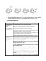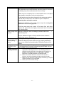
1
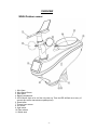
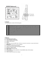
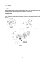
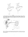
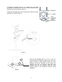
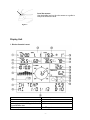
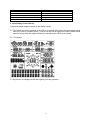
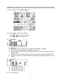
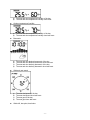
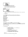
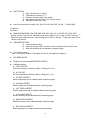
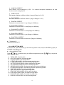
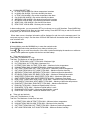
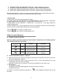
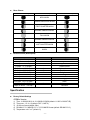
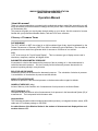
WH2303 PROFESSIONAL WEATHER STATION (WIND AND AIR PRESSURE) Operation Manual About this manual Thank you and congratulations on selecting this professional weather station! We are positive you will enjoy the benefits of accurate weather readings and the precise radio controlled time information that our instruments offer. This manual will guide you step-by-step through setting up your device. Use this manual to become familiar with your professional weather station, and save it for future reference. Glossary of Common Terms DCF/WWVB/MSF The DCF, WWVB or MSF time signal is an AM modulated time-of-day signal broadcasted by the Federal Government of Germany, NIST from USA or National Physical Laboratory. The time base is generated from an atomic time generator which is accurate to 10 billions of one second. LCD “LCD” is an acronym for ”Liquid Crystal Display”. This is a common type of display screen used in televisions, computers, watches, and digital clocks. BAROMETER & BAROMETRIC PRESSURE A barometer is a device that measures the pressure of the air pushing on it—this measurement is called the barometric pressure. We don’t actually feel the barometric pressure because the air pressure is pushing equally in every direction. RELATIVE AIR PRESSURE Relative air pressure is the same as the barometric pressure. The calculation of relative air pressure is a combination of the absolute air pressure and the altitude. ABSOLUTE AIR PRESSURE Absolute air pressure is the actual air pressure on the barometer without regard to altitude. INCHES OF MERCURY (inHg) Inches of Mercury is the common unit of measurement for air pressure in the United States. HECTOPASCALS (hPa) Hectopascals are the common units of measurement for air pressure in the International System (SI) of measurement. The hectopascal holds the same value Important Note: The Professional weather station includes a base station (receiver), an integrated outdoor sensor, USB cable and a PC software package on CD-ROM. An added feature of the Weather Station is the readout of all measured and displayed time and weather data on a PC. -1- OVERVIEW WH24 Outdoor sensor: 1. Wind Vane 2. Wind Speed Sensor 3. Solar panel 4. Battery compartment 5. LED Indicator: light on for 4s if the unit power up. Then the LED will flash once every 16 seconds (the sensor transmission update period). 6. Reset button 7. Thermo-hygro sensor 8. UV sensor 9. Light sensor 10. Rain collector 11. Bubble level -2- WH2303 Display unit DC connector USB interface Contents The weather station consists of the following parts. QTY 1 1 1 1 2 3 1 1 1 Item WH2303 Display Console WH24 Outdoor sensor(Thermo-hygrometer / Rain Gauge / Wind Speed Sensor /Transmitter) Wind Vane Stainless Steel Tube (D32*H200mm) U style Stainless Steel Loop AA 1.5V rechargeable batteries for outdoor sensor Zip bag for 1pc Allen wrench User manual 2 meters USB cable Features Time and date, Moon phase. Indoor temperature and humidity Outdoor temperature and humidity Wind chill, wind direction. Rainfall Display rain level and rainfall data in 24 hours, one week, one month, one year, total rain and rainfall event. Wind speed in mph, km/h, m/s, knots or Beaufort The direction of the wind with 360 degree Wind chill, dew point and heat index temperature display. Barometric, weather forecast. MAX, MIN value with time stamp. High/ low alarm. With message panel showing indication of alarms/Min/Max data, with time stamps Light and UV index Save the data when batteries are changed -3- PC software Installation Before placing and installing all components of the weather station at their final destination, please set up the weather station with all parts being nearby for testing the correct function. Outdoor sensor 1. Attach the wind vane Push the wind vane into the shaft. as shown in figure 1. Tighten the set screw with the Allen Wrench (included) as shown in figure 2. Make sure the wind vane spin freely. Figure 1 Figure 2 2. Insert the pole into the base, as shown in figure 3. Spin the lid onto the base as shown in figure 4. Togue and groove joint Figure 3 -4- Figure 4 3. Locate the battery door on the thermo-hygrometer / rain gauge transmitter, as shown in Figure 5. Turn the set screw counter clockwise to loosen the screw to open the battery compartment. Insert 3XAA rechargeable batteries in the battery compartment The LED indicator on the back of the transmitter will turn on for four seconds and normally flash once every 16 seconds (the sensor transmission update period). Figure 5 Note: If no LED light up or is lighted permanently, make sure the battery is inserted the correct way or a proper reset is happened. Do not install the batteries backwards. You can permanently damage the thermo-hygrometer. -5- 4. Fasten the mounting pole to your mounting pole or bracket (purchased separately) with the two U-bolts, mounting pole brackets and nuts, as shown in Figure 6. Tighten the mounting pole to your mounting pole with the U-Bolt assembly, as shown in Figure 7.. Figure 6 Figure 7 there are four alphabet letter of “N”,”E”,”S” and “W” representing for the direction of North, East, South and West, as Figure 8. Wind direction sensor has to be adjusted so that the directions on the sensor are matching with your real location. Permanent wind direction error will be introduced when the wind direction sensor is not positioned correctly during installation. Figure 8 -6- Level the sensors Use the bubble level on the rain sensor as a guide to verify that sensors are level. Figure 9 Display Unit 1. Display Console Layout 1.Time 3.Indoor Humidity 5. Barometric Pressure graph 7. Message panel showing indication of alarms/Min/Max data 9.Time stamp 2.Indoor Temperature 4.Barometric Pressure 6.Weather icon 8. Minimum 10.RF signal -7- 11.Memory status 13.Wind direction 15.Wind speed 17.Outdoor Humidity 19.UV index 21.Date 12. RCC signal 14.Rain fall 16.Dew point 18.Outdoor Temperature 20.Light 2. Initial Display Console Set Up Connect the power adapter to power up the display console. 2.1 The unit will turn on all segments of the LCD for 3 seconds after power reset and display setting value (RCC and RF frequency option). Then the unit will start to register the outdoor channel which takes 3 minutes. When the register finished, the unit will enter the RCC receive mode. 2.2 Full display 2.3 Key function, the display console has eight keys for easy operation, -8- SET: ALARM: HISTORY: MIN/MAX: : : : : Select the setting unit / enter setting mode Display high or low alarm function / on/off the alarm Display history records / return to normal mode Display the MAX, MIN value Select previously information / Increase or change the set parameter. Select next information / decrease or change the set parameter. Select the active unit. Select the active unit. Console Operation Program mode The screen is divided into 10 segments for selection and there are message display panel on the bottom. There are six program modes: normal, setting mode, history mode, alarm mode, max/min mode and calibrated mode. All the modes can be exited at any time by pressing the HISTORY key, or waiting for a 30 second timeout to take effect. Normally, if the segment selected has multi parts, press SET key to choose different part. Example: the current section is RAIN, you can press SET key to select among RAIN RATE, RAIN EVENT, DAY, WEEK, MONTH, YEAR and TOTAL. 1. Quick Display Mode(Update every 5 Seconds) In the normal mode and once some segment is selected ( Different segments can be chosen by pressing” ” or ” ” key. And the default selected segment is time and date), there will be -9- messages take turns to show on the message panel. If there are alarms occurred, the alarm information will be displayed in real time as well. The messages are showing one by one automatically or you can transfer by pressing” Note: Press fast switch to next message fast switch to previous message. Press or to select segments. Time and date f) g) Week and year (TUESDAY 2013) Alarm time Sunrise and sunset time stamp in the message panel (SUNRISE SUNSET ) Moon phase. (see moon phases part illustration on Page 19) If device received the RCC time successfully and the time is DST, it will display “DAYLIGHT SAVING TIME”. If without RCC function and the DST flag is ON, will also display “DAYLIGHT SAVING TIME”. If device is connected to outdoor transmitter successfully, it will display transmitter ID for 120 second. Light and UVI a) b) c) d) ” button. Press a) b) c) d) e) ” or “ The max light of the day. The max light since last reset The max UVI of the day. The max UVI since last reset. Indoor temperature - 10 - a) b) Outdoor temperature/ humidity a) b) The max and min absolute barometric of the day The max and min absolute barometric since last reset. The max and min relatively barometric of the day The max and min relatively barometric since last reset. Wind and gust speed a) b) c) d) The max and min temperature/ humidity of the day The max and min temperature/ humidity since last reset. Barometric a) b) c) d) The max and min temperature/ humidity of the day. The max and min temperature/ humidity since reset. The max wind speed of the day The max wind speed since last reset. The max gust of the day The max gust since last reset. Wind chill, dew point, heat index - 11 - a) b) c) d) The max of dew point, heat index of the day. The min of wind chill, dew point of the day. The max of dew point, heat index since last reset. The min of wind chill, dew point since last reset. Rainfall a) b) The max Rainfall of rainfall rate of the day. The max Rainfall since last reset (including rainfall rate during 1 day, 1 week, 1 month, and 1 year). 2. Setting Mode 2.1 In normal mode, press SET key for 2 seconds to enter the setting mode. Then press ” ”button, you will transfer among the main menu with options of : TIME SETTING UNIT SETTING Record save interval Rain sensor setting Barometric setting Contrast setting Key Beep Setting REREGISTER Transmitter Calibration setting Transmitter ID Choose one option and then press ” ” button, you will enter the sub menu. Press / key to transfer the unit or change the value. Hold the / key for 2 seconds will increase/decrease digits in great steps. Press HISTORY key or wait for 30 seconds at any time, device will return to normal mode. Sub menus of every option: TIME SETTING a) b) c) d) e) f) g) h) i) 12H/24H format select MM-DD-YYYY / DD-MM-YYYY / YYYY-MM-DD select Set time (hour, minute) Set clock (month, day, year) Time Zone select RCC ON/OFF select (if have RCC function) Daylight saving settings (DST ON/OFF) Set Latitude (NORTH or SOUTH, latitude value). Set longitude (EAST or WEST, longitude value). RCC mode: DCF: if RCC is OFF, the Daylight saving settings will display. - 12 - UNIT SETTING a) b) c) d) e) Light unit select (lux, fc, w/m2) Temperature unit select (C, F) Pressure unit select (hpa, inhg, mmhg) Wind speed unit select (km/h, m/s, bft, mph, knots) Rainfall unit select (mm, inch) Save record interval time setting: 16S, 24S, 32S, 40S, 48S, 56S, 1M, 2M, …, 239M, 240M. S; Seconds M: Minute RAIN SEASON BEGIN (JAN, FEB, MAR, APR, MAY, JUN, JUL, AUG, SEP, OCT, NOV, DEC) Default: January. The total rain falls before that will be cleared once it comes to 0:00 of January 1 st. Means the new statistic annual of rain fall begins from 0:00 of January 1st.Users can choose from January to December PRESSURE SETTING a) Current weather setting. b) Select the synoptic chart, Pre-set the value of weather and Pre-storm value. c) Select the historical time coordinates of pressure graph. LCD contrast setting. Level 1-9 for option. Default: 5.The higher the level is, the brighter the display is. KEY BEEP ON/OFF Register new transmitter(REREGISTER ON/OFF) Calibration setting a) LIGHT FACTOR LUX index calibration coefficient: default 1. (Range is 0.1-10) b) UV FACTOR UV factor calibration coefficient: default 1 (Range is 0.1-10) c) IN TEMP CORRECT Indoor temperature can be calibrated within measuring range. d) IN HUMI CORRECT Indoor humidity can be calibrated within measuring range. e) OUT TEMP CORRECT Outdoor temperature can be calibrated within measuring range. f) OUT HUMI CORRECT Outdoor humidity can be calibrated within measuring range. g) ABS PRESS CORRECT Absolute pressure can be calibrated within measuring range. h) REL PRESS CORRECT Relatively pressure be calibrated within measuring range. - 13 - i) WIND DIR CORRECT Wind direction can be adjusted by 0-359°.For southern hemisphere installations, the wind direction need to change by 180°. j) WIND FACTOR Wind speed calibration coefficient: default 1 (range is Range is 0.1-2.5) k) RAIN FACTOR Rain factor calibration coefficient: default 1 (range is Range is 0.1-2.5) l) RAIN DAY CORRECT Calibration for total rain falls of 1 day. (Range is 0-9999mm) m) RAIN WEEK CORRECT Calibration for total rain falls of 1 week (Range is 0-9999mm) n) RAIN MONTH CORRECT Calibration for total rain falls of 1 month (Range is 0-9999mm) o) RAIN YEAR CORRECT Calibration for total rain falls of 1 year (Range is 0-9999mm) p) RAIN TOTAL CORRECT Calibration for total rain falls since last reset. (Range is 0-9999mm) Transmitter ID Display the transmitter ID. 2.2 ALARM SETTING MODE In normal mode, press ALARM key you will enter high alarm mode, and press ALARM key again you will switch to low alarm mode. HIGH ALARM SETTING Press / key to transfer among the different segments and press value of the high alarm. a) b) c) d) e) f) g) h) i) j) k) l) m) n) o) TIME ALARM –Set time alarm. LIGHT HIGH ALARM --Set light high alarm UVI HIGH ALARM --Set UVI high alarm In TEMP HIGH ALARM --Set indoor temperature high alarm In HUMI HIGH ALARM --Set indoor humidity high alarm Out TEMP HIGH ALARM Set outdoor temperature high alarm Out HUMI HIGH ALARM Set outdoor humidity high alarm ABS BARO HIGH ALARM --Set absolute barometric pressure high alarm REL BARO HIGH ALARM --Set relatively barometric pressure high alarm WIND HIGH ALARM --Set wind speed high alarm GUST HIGH ALARM --Set gust speed high alarm DEW POINT HIGH ALARM --Set dew point high alarm HEAT INDEX HIGH ALARM --Set heat index high alarm RAIN RATE HIGH ALARM --Set rainfall rate high alarm RAIN DAY HIGH ALARM --Set rainfall day high alarm - 14 - / key to adjust the a) b) c) d) e) f) g) h) LOW ALARM SETTING In TEMP LOW ALARM--Set indoor temperature low alarm In HUMI LOW ALARM --Set indoor humidity low alarm In TEMP LOW ALARM --Set outdoor temperature low alarm Out HUMI LOW ALARM --Set outdoor humidity low alarm ABS BARO LOW ALARM --Set absolute barometric low alarm REL BARO LOW ALARM --Set relatively barometric low alarm WIND CHILL LOW ALARM --Set wind chill low alarm DEW POINT LOW ALARM --Set dew point low alarm In alarm setting mode, you can press the SET key to choose turn on or/off the alarm. Press ALARM key, you can switch between high alarm and low alarm setting. Press HISTORY key or wait for 30 seconds at any time, you will return to normal mode. When alarm occurs, the alarm information will be displayed in real time on the message panel. You can press any key to stop it. But the alarm ICON will still flash until the weather data doesn’t meet the user set alarm level. 3. Max/Min Mode In Normal Mode, press the MIN/MAX key to enter the max/min mode. Press MIN/MAX select today max/history max /today min/history min. Press / key to enter the sub menu of the each 4 options and display the maximum or minimum values of each parameter together with the time and date stamp. Today max and total max: Today max: The Maximum of 1 day Total max: The Maximum of total since last reset a) LIGHT TODAY MAX, LIGHT TOTAL MAX-- Maximum Light b) UV TODAY MAX, UV TOTAL MAX-- Maximum UVI. c) IN TEMP TODAY MAX, IN TEMP TOTAL MAX -- Maximum Indoor temperature. d) IN HUMI TODAY MAX, IN HUMI TOTAL MAX -- Maximum Indoor humidity. e) OUT TEMP TODAY MAX, OUT TEMP TOTAL MAX – Maximum Outdoor temperature. f) OUT HUMI TODAY MAX, OUT HUMI TOTAL MAX -- Maximum Outdoor humidity. g) ABS BARO TODAY MAX, ABS BARO TOTAL MAX -- Maximum Absolute barometric. h) REL BARO TODAY MAX, REL BARO TOTAL MAX -- Maximum Relatively barometric. i) WIND SPEED TODAY MAX, WIND SPEED TOTAL MAX -- Maximum Wind speed. j) GUST SPEED TODAY MAX, GUST SPEED TOTAL MAX -- Maximum Gust speed. k) DEW POINT TODAY MAX, DEW POINT TOTAL MAX -- Maximum Dew point temperature. l) HEAT INDEX TODAY MAX, HEAT INDEX TOTAL MAX -- Maximum Heat index temperature. m) RAIN RATE TODAY MAX, RAIN RATE TOTAL MAX -- Maximum Rainfall rate. n) RAIN 24H TOTAL MAX -- Maximum Rainfall within 24 hours. o) RAIN WEEK TOTAL MAX -- Maximum Rainfall within 1 week p) RAIN MONTH TOTAL MAX -- Maximum Rainfall within 1 month q) RAIN YEAR TOTAL MAX -- Maximum Rainfall within 1 year. Today min and total min: Today min: The Maximum of 1 day Total min: The Maximum of total since last reset a) b) c) d) IN TEMP TODAY MIN, IN TEMP TOTAL MIN -- Minimum Indoor temperature. IN HUMI TODAY MIN, IN HUMI TOTAL MIN -- Minimum Indoor humidity. OUT TEMP TODAY MIN, OUT TEMP TOTAL MIN -- Minimum Outdoor temperature. OUT HUMI TODAY MIN, OUT HUMI TOTAL MIN -- Minimum Outdoor humidity. - 15 - e) f) g) h) ABS BARO TODAY MIN, ABS BARO TOTAL MIN -- Minimum Absolute barometric. REL BARO TODAY MIN, ABS BARO TOTAL MIN -- Minimum Relatively barometric WIND CHILL TODAY MIN, WIND CHILL TOTAL MIN -- Minimum Wind chill temperature DEW POINT TODAY MIN, DEW POINT TOTAL MIN -- Minimum Dew point temperature Each Maximum/minimum value can be cleared by pressing SET key for 2 seconds during this mode. Press the HISTORY key or wait for 30 seconds will lead to Normal Mode. 5. History mode In normal mode, press the history key switch to history. If no history data, it will show “HISTORY” and “NONE RECORD” on the message pane.. Otherwise it will display message like”HISTORY P/R 1.01”and “YEAR / SECOND 13.06”. P means PAGE, R means RECORD. 1 is PAGE No., 01 is record No.. Every page includes 32 records of history data. “YEAR / SECOND 13.06”. is a time stamp of the record. 13 means 2013 year,06 is the second stamp. The hour, minute, and date stamp will be shown on the time segment. Press the / Press the / key to switch to next/pre record. key to switch to next/pre page record. Other Console Functions Weather Tendency indicators There are tendency indicators besides the indoor/outdoor temperature and humidity segments. The standard of detection is as bellow: Tendency indicators Rising Steady Falling humidity Temperature Rising rate>= 10% within 30 minutes Change rate < 10% within 30 minutes Falling rate >= 10% within 30 minutes Rising >= 1℃ within 30 minutes Change rate < 1℃ within 30 minutes Falling >= 1℃ within 30 minutes Radio Controlled Clock (RCC) - Optional 3.1 First time unit power on. Once the device get the data from the transmitter, it will start to receive the RCC automatically after 3 minutes 3.2 If failed to receive the RCC, device will retrieve RCC at some pre-determined time spot automatically:2:00, 8:00, 14:00, and 20:00; It will stop to retrieve RCC once the RCC is received successfully for once within 1 day. 3.3 Exit condition: 3.31 Any key is pressed. 3.32 3 Minute (not received start signal) or 8 minute auto time out reached. 3.33 Receive success. 3.4 If RCC is received successfully, the signal icon be hidden. - 16 - will be displayed. Otherwise the icon will Moon Phases Icon: Northern Hemisphere Moon Phase Description Icon: Southern Hemisphere NEW MOON WAXING CRESCENT MOON FIRST QUARTER MOON WAXING GIBBOUS MOON FULL MOON WANING GIBBOUS MOON LAST QUARTER MOON WANING CRESCENT MOON Beaufort Scales (Wind Speed) Wind speed 0-1mph(0-1.6kph) 1-3mph(1.6-4.8kph) 3-7mph(4.8-11.3kph) 7-12mph(11.3-19.3kph) 12-18mph(19.3-29.0kph) 18-24mph(29.0-38.6kph) 24-31mph(38.6-49.9kph) 31-38mph(49.9-61.2kph) 38-46mph(61.2-74.1kph) 46-54mph(74.1-86.9kph) 55-63mph(88.5-101.4kph) 64-73mph(103-117.5kph) 74mph or above(119.1kph) Beaufort number 0 1 2 3 4 5 6 7 8 9 10 11 12 Description Calm Light air Light breeze Gentile breeze Moderate breeze Fresh breeze String breeze Near gale Gale Strong gale Storm Violent storm Hurricane Specification Factory Default Settings 433MHz Version: 1) 2) 3) 4) 5) Time: 1/1/2000 0:00:00 31/12/2099 23:59:59 (default: 1/1/2013 0:00 00 TUE) Time zone: -12 +12 (default: DCF:1, MSF:0) 12/24 hour format (default: 24hr) DD-MM-YYYY / MM-DD-YYYY / YYYY-MM-DD format (default: DD-MM-YYYY) Temperature unit C or F (default: C) - 17 - 6) 7) 8) 9) 10) 11) 12) 13) 14) 15) 16) 17) 18) 19) 20) 21) 22) 23) 24) 25) 26) 27) 28) 29) 30) 31) 32) 33) 34) 35) 36) Wind speed units: km/h, m/s, bft, mph, knots (default: km/h) Average wind speed / gust wind speed (default: average wind speed) Pressure units: hpa, mmHg, inHg (default: hpa) Weather forecast: 2, 3, 4 (default: 2) Storm: 39 (default: 4) Time format of history graph: 12h, 24h (default: 12h) Pressure display: absoluteness or relative (default: relative) Forecast : sun, partly cloudy, cloudy, rain, rain storm (default: partly cloudy) Temperature exponent: wind chill, dew point, heat index (default: dew point) Light units: lux, fc, w/m2 (default: w/m2) Rainfall units: mm, inch (default: mm) Rainfall display: rainfall rate/rainfall event/24H/WEEK/MONTH/YEAR (default: RAINFALL RATE) Rainfall of year season begin (default: JAN) Time alarm: 0:00 23:59 (default: 0:00, disable) Indoor temperature high alarm: -9.9 60.0C (14F 140F) (default: 20.0C, disable) Indoor temperature low alarm: -9.9 60.0C (14F 140F) (default: 0.0C, disable) Indoor humidity high alarm: 1% 99% (default: 65%, disable) Indoor humidity low alarm: 1% 99% (default: 35%, disable) Outdoor temperature high alarm: -40.0 60.0C (-40F 140F) (default: 30.0C, disable) Outdoor temperature low alarm: -40.0 60.0C (-40F 140F) (default: -10.0C, disable) Outdoor humidity high alarm: 1% 99% (default: 75%, disable) Outdoor humidity low alarm: 1% 99% (default: 45%, disable) Wind chill temperature low alarm: -40.0 60.0C (-40F 140F) (default: 0.0C, disable) Dew point temperature high alarm: -40.0 60.0C (-40F 140F) (default: 10.0C, disable) Dew point temperature low alarm: -40.0 60.0C (-40F 140F) (default: -10.0C, disable) Heat index temperature high alarm: -40.0 60.0C (-40F 140F) (default: 27.0C, disable) Rainfall alarm: rainfall rate and rainfall 24H: 0-999.9mm (default: 0.0mm, disable) Wind speed alarm: 0-50.0m/s (default: 1.8km/h, disable) Guest speed alarm: 0-50.0m/s (default: 3.6km/h, disable) Light high alarm: 0 to 300000 (default: 200000lux, disable) UVI high alarm: 0 to 15 (default: 10, disable) Specifications Outdoor data Transmission distance in open field : Frequency : up to 150m (330 feet) 433 MHz Temperature range Accuracy Resolution : : : -40˚C--60˚C + / - 1 °C 0.1˚C Measuring range rel. humidity Accuracy : : 1%~99% +/- 5% Rain volume display Accuracy Resolution : : : 0 – 9999mm (show --- if outside range) + / - 10% 0.3mm (if rain volume < 1000mm) 1mm (if rain volume > 1000mm) Wind speed Accuracy: : 0-50m/s (0~100mph) (show --- if outside range) +/- 1m/s (wind speed< 5m/s) +/-10% (wind speed > 5m/s) - 18 - Light Accuracy : : UVI range : 0-300k Lux +/-15% 0 to 15 index (0 to 2000 w/m2) Indoor data Indoor temperature range Resolution : : -9.9˚C--60˚C (show --- if outside range) 0.1˚C Measuring range rel. humidity Resolution : : 1%~99% 1% Measuring range air pressure Accuracy Resolution : : : Power consumption Base Station Remote sensor : : Battery life : 300-1100hPa (8.85-32.5inHg) +/-3hpa under 700-1100hPa 0.1hPa (0.01inHg) 3 X AA 1.5V LR6 Alkaline batteries (not included) 3 x AA 1.5V rechargeable batteries (included) *** Or normal Alkaline batteries can also be safely used Minimum 12 months for thermo-hygro sensor Maintenance 1. Clean the rain gauge once every 3 months as follows. Reference Figure 11. Step 1: Make a note of the current rain totals by referencing the calibration screen (reference Section Error! Reference source not found.). You will need to re-enter these values after the calibration procedure it complete. Step 2: Pour water into the rain collector to moisturize the dirt inside rain bucket. Step 3: Use an approximately 3 inch (80 mm) long cotton swab, and push the cotton tip through the rain collector hole until it reaches the self-emptying mechanism, and press until the mechanism no longer rotates. Step 4: Rotate the cotton swab back and forth, removing dirt from the tipping mechanism and rain collector hole. Step 5: Remove the cotton swab and flush with water to remove any remaining dirt. Step 6: Re-enter the rain totals recorded in Step 1. - 19 - Figure 11 2. Clean the solar radiation sensor every 3 months with water and towel. 3. Replace rechargeable batteries every 2 to 3 years. Can also safely use ordinary Alkaline batteries. Standard NiMh/LiIon/NiCd 1.2V rechargeable batteries should not be used. Troubleshooting Guide Problem Wireless remote (thermo-hygrometer) not reporting in to console. Solution The maximum line of sight communication range is about 300’. Move the sensor assembly closer to the display console. There are dashes on the display console. Install a fresh set of batteries in the remote sensor(s). Resynchronize the remote sensor(s). Reference Section 4.4. Make sure the remote sensors are not transmitting through solid metal (acts as an RF shield), or earth barrier (down a hill). Radio Frequency (RF) Sensors cannot transmit through metal barriers (example, aluminum siding) or multiple, thick walls. Outdoor sensor array does not communicate to the display console. Move the display console around electrical noise generating devices, such as computers, TVs and other wireless transmitters or receivers. The sensor array may have initiated properly and the data is registered by the console as invalid, and the console must be reset. The reset button is next to the LED, near the mounting point on the sensor array, as shown in figure10. With an open ended paperclip, press the reset button for 3 seconds to completely discharge the voltage. Take out the batteries and wait one minute, while covering the solar panel to drain the voltage. Put batteries back in and resync with console by powering down and up the console with the sensor array about 10 feet away. Bring the sensor array inside the house (you can disconnect it from the rest of the sensors). The LED next to the battery compartment will flash every 16 seconds. If the LED is not flashing every 16 seconds… Replace the batteries in the outside sensor array. Non-rechargeable - 20 - Problem Solution batteries are OK for testing purposes. If the batteries were recently replaced, check the polarity. If the sensor is flashing every 48 seconds, proceed to the next step. There may be a temporary loss of communication due to reception loss related to interference or other location factors, or the batteries may have been changed in the sensor array and the console has not been reset. The solution may be as simple as powering down and up the console. Replace the batteries in the outside sensor array. Non-rechargeable batteries are OK for testing purposes. Temperature sensor reads too high in the day time. Absolute pressure does not agree with official reporting station Rain gauge reports rain when it is not raining Data not reporting to Wunderground.com With the sensor array and console 10 feet away from each other, remove AC power from the display console and wait 10 seconds. Re-connect power. Make certain that the sensor array is not too close to heat generating sources or strictures, such as buildings, pavement, walls or air conditioning units. Use the calibration feature to offset installation issues related to radiant heat sources. Reference 4.3. You may be viewing the relative pressure, not the absolute pressure. Select the absolute pressure. Make sure you properly calibrate the sensor to an official local weather station. Reference Section 4.3 for details. An unstable mounting solution (sway in the mounting pole) may result in the tipping bucket incorrectly incrementing rainfall. Make sure you have a stable, level mounting solution. 1. Confirm your password is correct. It is the password you registered on Wunderground.com. Your Wunderground.com password cannot begin with a non-alphanumeric character (a limitation of Wundeground.com, not the station). Example, $oewkrf is not a valid password, but oewkrf$ is valid. 2. Make sure the date and time is correct on the console. If incorrect, you may be reporting old data, not real time data. 3. Make sure your time zone is set properly. If incorrect, you may be reporting old data, not real time data. 4. Check your router firewall settings. - 21 - Weather Smart PC Software User Manual 1.0 General Information The Weather station is a weather monitoring device that achieves displays and records the weather data from internal and external sensors. Besides the indoor temperature, indoor humidity and air pressure measured by internal sensor, it will receive the outdoor temperature and humidity, wind and rainfall. Light & UVI and Heat index transmitted by outdoor sensor as well. After installing the “Weather Smart” program on the CD-ROM in package, It can show you all the weather data from the base station including data from both indoor and outdoor sensors. For operation, simply use the USB cable supplied and connect the Base Station to the PC. From now on you can start to track current and history weather information at your finger tips. 2.0 System Requirements To install the “WeatherSmart” software onto your PC, the minimum requirements for PC are as follows: Operating System: Windows 2000, Windows XP, Windows Vista. Windows 7, Windows 8 Internet Explorer 6.0 or above Processor: Pentium III 500 MHz or above Memory: at least 128MB, 256MB recommended CD-ROM Drive Base Station and PC must be connected by USB cable 3.0 Installation of the “Weather Smart” Software Firstly, the Base Station and the Outdoor Sensors should be connected and checked for correct function (see Operation Manual for Professional Weather Station for setting up the Weather Station). After successful checking, install the “Weather Smart” software as follows: 1. 2. 3. 4. 5. 6. Switch on your PC and insert the CD-ROM into the CD-ROM Drive. Double click “Weather Smart.exe”” Select the installation process language option and click ok click next and select the destination folder(change directory when needed) click next and select the shortcut folder(change directory when needed) click next and select the additional tasks. 7. Click next and setup is now ready to begin installing Weather Smart on your computer. 8. Click install, software will be installed automatically - 22 - 9. Press Finish to finish the installation process and exit. If you tick “Launch Weather Smart” the software will start to run. 10. From “Start—All Programs—Weather Smart” path and double click the “Weather Smart” icon to start application. Note: The graphic function needs the software to be installed under the administrator account. If it is installed under limited user accounts, the graphic function of the software might not be working correctly. 3.0 Basic Settings of the “Weather Smart” Software After the “EasyWeather.exe” program has been started, the following main window will appear on the PC screen: All the settings from the base unit is mirrored into the PC software, so once you have done your setting on the base unit, then you don’t need to make any setting changes on the PC software. However you can still easily make any setting changes you wanted from the PC and download the changes into the base station (the setting change will be refreshed when next full minute arrives on the base station). When the base unit is connected to PC, it shows “USB Connected” at the bottom of screen. If no base station is connected, it shows “USB Unconnected”. Tool Bar: The tool bar at the top of the screen has 3 options; System, Record and Help. 4.1 System option - 23 - 4.1.1 Click System button, enters the Setting menu This section is used to set up PC software display, base station units. Once you made your choice, press Save to make the setting effective. 4.1.2 Click Alarm button, enters the Alarm menu - 24 - This section is used to set the desired time, high or low alarm value for the base unit, as well as able or disable the corresponding alarm function. Once you made your choice, choose Save to make the setting effective. If you don’t want to make any change, just press Cancel and exit without change. 4.1.3 Click Max/Min day button, enters the Max/Min day menu This section is used to display the recorded the min and max alarm time. - 25 - 4.1.4 Click Max/Min button, enters the Max/Min menu This section is used to display the recorded min and max value recorded with time stamp. Min/Max reset can only be done through key operation on the base station. 4.1.5 Click Language button, enters the Language menu 4.2 Record option - 26 - 4.2.1 Click History button, enters the History menu This section is used to display recorded history data in a spread sheet. If you wanted to see all history data in a desired time period, choose the time duration and press Search to reload the history data. With the Export button, you can export the selected history data into excel format file for other application purpose. When memory on base station is full, press “Clear Memory” button to refresh the memory space on the base station (remember to upload all data before pressing this button). If you wanted to start a new weather history record, press “Clear Data” button to clear up the data base, all history weather data will be deleted (if you would like to keep a back up history file before deleting all weather data, you can make a copy of the “WeatherSmart.mdb” file into another folder or just rename the “WeatherSmart.mdb” file, such as “Jan-07.dat”, for future reference.) 4.2.2 Click Graph button, enters the Graph menu - 27 - In this section, you can see the history data plotted in graph format for easier observation. If you want to see more details, just use your mouse to select the area you wanted and the display will be automatically updated in more detailed scale: - 28 - With the Export as image button, you can export the selected graph into .jpeg format file. You can change the Y axel by scrolling the mouse up and down roller. What to do if graph function is not working This is the most encountered problem with this software. To make the graph function working properly, please check the following step: 1, find the folder where the “WeahterSmart.exe” file is located 2. Create a file name “reg_graph.bat” file with wordpad or notepad editor program 3. Type “regsvr32 WeatherSmart.ocx” and save the reg_graph.bat file 4. Double click “reg_graph.bat” file and it should register the graphic driver again. If successful, then the following window will be displayed: 4.3 Upload option - 29 - 4.3.1 Click Upload button, enters the upload menu Note: This feature is only available in EasyWeather Version 8.3 or greater. To upload weather data to the internet, from EasyWeather, select Upload from the menu bar. User can upload data to website. www.wundergound.com or their own website. If user choose www.wundergound.com, he do not need to set the server, server type and port. If user choose custom, he need to set the server, server type and port. To upload data to Wunderground.com, you must first register on the Wunderground.com website. Registration is free. 1. Visit http://www.wunderground.com/ and select Join if you do not have an account. - 30 - 2. Once registered with Wunderground.com you will need to sign up your station. To get started visit: http://www.wunderground.com/weatherstation/setup.asp 3. Enter your Station ID, and password into the ID and Password fields provided in the EasyWeather software, and select the Auto Upload checkbox. Please Note: Make sure you enter the ID in all capitals, and the password exactly as you chose it, both fields are case sensitive. 4.4 Help option Click About “WeatherSmart” button, enters the About menu Special Notes about time synchronization between PC and sub-station: The PC software obtained its own time scale through the time interval marker from the base station history data, and the PC software automatically synchronizes the weather data with a time stamp calculated. Thus the history data file can have different time when the PC time and base station time is not same. In order to make the time scale correct, remember to set the PC time and base station time same, and further to this, no weather data is allowed to be missed or over-written. If history weather memory on the base station is cleared by manual setting, then the history weather data since last uploading is lost permanently. Before memory is used up(memory icon on LCD display showing 100% full), remember to upload weather history data to PC periodically. If there is a reset happened for the rain fall on the base station, then there will be rain fall value discrepancy between PC and base station. Legal Notes We reserve the right to delete or change any image whether or not purposely uploaded onto the server by a user of the Professional weather station and the WeatherSmart Software products. The WeatherSmart software products are protected by copyright laws and international copyright treaties as well as other intellectual property laws and treaties. You may not copy the printed materials accompanying the products. - 31 -