1
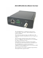
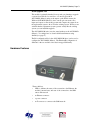
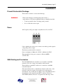
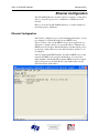
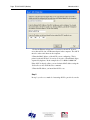
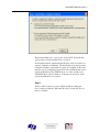
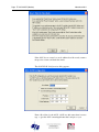
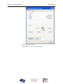
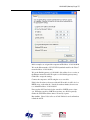
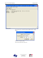
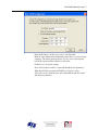
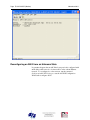
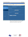
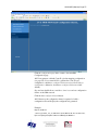
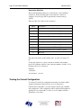
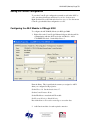
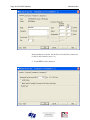
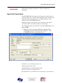
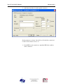
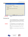
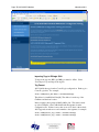
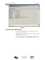
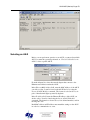
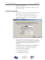
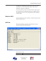
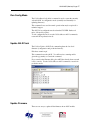
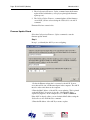
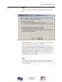
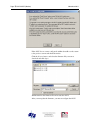
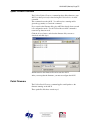
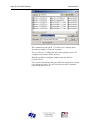
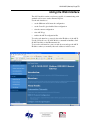
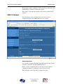
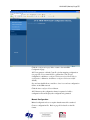
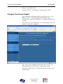
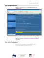
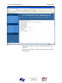
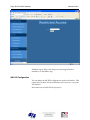
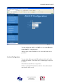
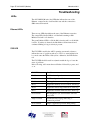
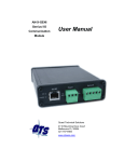
AN-X-MOD (Monitor)
Modicon
S908 Remote I/O
Monitor
User Manual
Page 2 AN-X-MOD (Monitor)
November 2011
Because of the variety of uses for the products described in this
publication, those responsible for the application and use of these
products must satisfy themselves that all necessary steps have been taken
to assure that each application and use meets all performance and safety
requirements, including any applicable laws, regulations, codes and
standards. In no event will Quest Technical Solutions be responsible or
liable for indirect or consequential damage resulting from the use or
application of these products.
Any illustrations, charts, sample programs, and layout examples shown
in this publication are intended solely for purposes of example. Since
there are many variables and requirements associated with any particular
installation, Quest Technical Solutions does not assume responsibility or
liability (to include intellectual property liability) for actual use based
upon the examples shown in this publication.
Throughout this manual we use notes to make you aware of safety
considerations.
Identifies information about practices or circumstances that can lead to
personal injury or death, property damage, or economic loss.
These warnings help to:
WARNING!
IMPORTANT!
TIP
•
identify a hazard
•
avoid the hazard
•
recognize the consequences
Identifies information that is especially important for successful
application and understanding of the product.
Identifies information that explains the best way to use the AN-X-MOD
(Monitor)
Microsoft is a registered trademark of Microsoft Corporation.
Windows, Windows XP Windows Vista and Windows 7 are trademarks of Microsoft Corporation.
ControlLogix, RSLinx and RSLogix 5000 are trademarks of the Allen-Bradley Company, Inc.
AN-X-MOD (MONITOR) MODULE OVERVIEW
2
Hardware Features
3
Package Contents
4
Modes of Operation
4
INSTALLATION
5
Prevent Electrostatic Discharge
5
Power
5
S908 Cabling and Termination
5
Ethernet Cabling
6
Software Installation
6
QUICK START
7
ETHERNET CONFIGURATION
8
Ethernet Configuration
Standalone Computer
8
13
Reconfiguring an AN-X from an Unknown State
18
S908 NETWORK CONFIGURATION
19
Autoconfiguration
19
Manual Configuration
22
Configuration File Format
23
Viewing the Current Configuration
25
Saving the Current Configuration
25
Supported Modicon Modules
25
EXCHANGING SCHEDULED DATA WITH A CONTROLLOGIX
26
Mapping I/O Data
26
Page 4 AN-X-MOD (Monitor)
Other Mappable Data
November 2011
29
Viewing the Current Configuration
32
Saving the Current Configuration
33
Configuring the AN-X Module in RSLogix 5000
33
Input Only Connections
35
ControlLogix Tags
37
Using the ControlLogix Log
39
CONVERTING AN APPLICATION TO AN-X-MOD (MASTER)
40
USING ANXINIT
41
AnxInit Log
41
Locating Available AN-X Modules
42
Selecting an AN-X
43
Set AN-X IP Configuration
44
Restart an AN-X
45
AN-X Info
45
Read Kernel Parameters
46
Run Config Mode
47
Update AN-X Flash
47
Update Firmware
Firmware Update Wizard
Update Firmware Command
47
48
51
Patch Firmware
51
USING THE WEB INTERFACE
53
S908 I/O Network
54
Configure ControlLogix Support
56
View Configuration Files
57
View Active Configuration
57
Log Files
System Error Log
System Info Log
ControlLogix Log
View All Logs
59
59
59
59
59
Administration Menu
Browse File System
AN-X IP Configuration
Archive Configuration
59
59
60
61
TROUBLESHOOTING
62
LEDs
Ethernet LEDs
SYS LED
NET LED – Network Status
62
62
62
63
Logs
63
Diagnostic Counters
63
UPDATING THE FIRMWARE
64
Reading Version Numbers
64
SPECIFICATIONS
65
SUPPORT
66
WARRANTY
67
AN-X-MOD (Monitor) Module Overview
The AN-X-MOD (Monitor) communications module connects a
ControlLogix PLC or other device to a Modicon S908 remote I/O
network, over Ethernet.
The module monitors inputs and outputs on the S908 network. The
module supports 800 series and Quantum remote drops. It supports up to
32 drops.
The module supports scheduled connections with a ControlLogix
processor, over Ethernet, so the ControlLogix processor can read inputs
and outputs from the Modicon network.
Both the S908 and ControlLogix configurations can be generated
automatically by the AN-X from data captured from the S908 network.
The AN-X-MOD (Monitor) module has a web interface for
configuration. You can communicate with the module using any standard
web browser such as Internet Explorer.
The module firmware can be updated over Ethernet using the Windows
utility supplied. Refer to page 64 for details.
AN-X-MOD (Monitor) Page 3
As an Upgrade Tool
This module is primarily intended for users who are planning to upgrade
a system from a Modicon controller to a ControlLogix with an
AN-X-MOD (Master) acting as the master on the Modicon network.
With an AN-X-MOD (Monitor), the ControlLogix can monitor live
inputs and outputs on the existing system and compare the outputs from
the replacement system to those from the existing system. When you are
satisfied that the replacement system operates exactly like the existing
system, you can install the upgrade.
The AN-X-MOD (Monitor) uses the same hardware as the AN-X-MOD
(Master). You simply have to download different firmware using
AnxInit (see page 47).
The I/O configuration file for the AN-X-MOD (Monitor) can be used to
configure the AN-X-MOD (Master). The Ethernet/IP configuration is
different for the two modules since data is mapped differently.
Hardware Features
The module has:
•
LEDs to indicate the status of the connection to the Ethernet, the
module’s internal state, and state of the connection to the S908
remote I/O network
•
an Ethernet connector
•
a power connector
•
an F connector to connect to the S908 network
Page 4 AN-X-MOD (Monitor)
November 2011
Package Contents
•
AN-X-MOD module
•
CD containing software and documentation
•
rubber feet for desktop use
Modes of Operation
There are three AN-X modes of operation:
•
Boot mode. The AN-X is running its low level startup firmware.
•
Configuration mode. This is the mode when you are updating the
firmware in the AN-X.
•
Production mode. This is the normal runtime mode of operation.
AN-X-MOD (Monitor) Page 5
Installation
Prevent Electrostatic Discharge
The module is sensitive to electrostatic discharge.
WARNING!
Electrostatic discharge can damage integrated circuits or
semiconductors. Follow these guidelines when you handle the module:
•
Touch a grounded object to discharge static potential
•
Do not touch the connector pins
Power
AN-X requires a DC power input of anywhere from 12 to 24 VDC.
Left to right the pins on the power connector are chassis ground, negative
voltage and positive voltage.
The chassis ground should be connected.
Power consumption is 200 mA @ 12VDC or 100 mA @ 24VDC.
The part number for the power connector is Phoenix MSTB
2.5/3-ST-5.08
S908 Cabling and Termination
The AN-X-MOD (Monitor) module does not transmit on the S908
network. It does not occupy a drop number on the network.
The module has a standard F connector for connection to the S908
remote I/O network.
Since the module monitors communication between other nodes on the
network, it cannot be treated as just another node on the network.
Normally the only consideration in adding a node to the S908 network is
the attenuation of the signal from the PLC to the drop. However,
AN-X-MOD (Monitor) must also see signals from other drops on the
Page 6 AN-X-MOD (Monitor)
November 2011
network. A typical tap has a 14 dB drop from the network trunkline to
the node so if the AN-X is connected as a node, there would be an
immediate 28 dB drop in the signal from any other node on the network
to the AN-X. Also bear in mind that the network cable attenuates the
signal, typically 0.5 dB per 100 feet.
If possible the AN-X should be connected to the "trunk", not on a
dropline. There are only two ends to the trunk, and the master will be on
one end, so if possible put the AN-X-MOD (Monitor) on the other.
Ensure that the physical ends of the S908 remote I/O network are
properly terminated. Both the AN-X and the Modicon controller have
internal termination. Therefore, if they are at the physical ends of the
network, there should not be other terminators on the network trunk.
The AN-X module does not connect the S908 cable to earth ground. If a
connection to ground is required, use an F connector grounding block.
Ethernet Cabling
AN-X has a standard RJ-45 connector for connecting to Ethernet.
If you are connecting AN-X to an existing network through a router or
switch, use a standard Ethernet cable.
If you are connecting directly between a computer and AN-X, use a
crossover cable.
Software Installation
You must uninstall any previous version of the software before you can
install a new version. Use the Windows Control Panel Add and Remove
Programs to remove the old version.
Insert the CD supplied with the AN-X module and run the program
setup.exe on the CD.
AN-X-MOD (Monitor) Page 7
Quick Start
Step
See page
1
Install the AN-X Windows software
6
2
Power up the AN-X, connect it to Ethernet and use
AnxInit to assign it an IP address and download the
firmware
8
3
Connect AN-X to the Modicon S908 network
5
4
Use a web browser to connect to the the AN-X web
interface and use it to autoconfigure the Modicon
network and ControlLogix configuration
19
5
Select Automation Network/S908 I/O Network
Configuration
19
6
Click Clear Heard Configuration and then return
to configuration page
7
Stop and start the Modicon controller
8
Select whether the AN-X should generate the
ControlLogix configuration as well as the S908
configuration.
9
Click Auto-configure network. You should see a
list of the Modicon modules and their locations on
the S908 network. If you selected ControlLogix
configuration, you should also see the CLX
configuration it generated
10
Configure the AN-X in RSLogix 5000
11
Read inputs and outputs from the S908 network
12
Use the web interface to create tags for RSLogix
5000
37
13
Import the tags into RSLogix 5000
38
14
Use the tags to access data
33
Page 8 AN-X-MOD (Monitor)
November 2011
Ethernet Configuration
The AN-X-MOD (Monitor) module connects a computer or other device
such as a ControlLogix processor on Ethernet to an S908 remote I/O
network.
Before you can use the AN-X-MOD (Monitor), you must configure its
network properties on Ethernet.
Ethernet Configuration
AN-X can be configured to use a static (unchanging) IP address or it can
be configured to obtain its IP address from a DHCP server.
Unless you have control of the DHCP server, in most applications you
will want to configure AN-X to use a static IP address. Otherwise the
DHCP server may assign a different IP address each time AN-X powers
up, and any software that accesses the AN-X module would have to be
reconfigured.
AN-X is shipped with DHCP enabled. If it finds a DHCP server on the
network, the DHCP server assigns it an IP address. You can use the
utility AnxInit to find the IP address that the DHCP server has assigned.
Select Utilities/Locate All AN-X Modules and AnxInit will locate the
AN-X and display its IP address.
AN-X-MOD (Monitor) Page 9
If AN-X does not find a DHCP server within about three minutes of
starting up, it reverts to a temporary static IP address of 192.168.0.41 If
AN-X is using this temporary IP address, it repeatedly flashes the SYS
LED red three times followed by a pause. If your computer is on the
same subnet, you can use the web interface to change the IP address.
IMPORTANT!
Use this temporary IP address only for initial setup of AN-X. AN-X will
not function for its intended purpose at the temporary IP address.
If you are using multiple AN-X modules, configure them one at a time,
especially if there is no DHCP server on the network, since they will all
revert to the same temporary IP address when they fail to find a DHCP
server.
IMPORTANT!
If you are connecting AN-X to an existing Ethernet network, consult the
network administrator to obtain a static IP address for AN-X and to
obtain information about how you should configure AN-X.
IMPORTANT!
The AN-X must be on the local Ethernet (same subnet as your computer)
when you set its IP address.
You configure the Ethernet properties using the Windows utility AnxInit
supplied with AN-X or the AN-X web interface.
Use the Configuration/AN-X IP Settings command to start the AN-X IP
configuration wizard, which takes you step by step through the IP
configuration process.
Step 1
In step 1, you identify the AN-X you are configuring.
Page 10 AN-X-MOD (Monitor)
November 2011
1. Select the Ethernet adapter that’s connected to the AN-X. In most
cases there will be just one Ethernet adapter in the computer. The AN-X
must be on the same subnet as the computer.
2. Enter the MAC address of the AN-X you are configuring. This is
printed on the AN-X label. It consists of six pairs of hexadecimal digits,
separated by hyphens. In the example above, it’s 00-0c-1a-00-01-0d.
If the AN-X is already online, you can obtain its MAC address using the
Utilities/Locate All AN-X Modules command.
3. Enter the IP address you intend the AN-X to use.
Step 2
In step 2, you choose a method of restarting AN-X to put it in boot mode.
AN-X-MOD (Monitor) Page 11
The preferred method is to cycle power on the AN-X. Select the first
option on the screen and click the Next >> button.
An alternative method, useful if the AN-X in not easily accessible, is to
send it a command over Ethernet. The AN-X must be powered on and
completely running for this method to work. For example, if this is the
first time you are configuring a new AN-X, allow sufficient time for it to
acquire an IP address from a DHCP server or to time out and use its
default IP address (about 3 minutes). Select the second option on the
screen and click the Next >> button.
Step 3:
Wait for AN-X to enter boot mode. While AnxInit is waiting, the
Next>> button is disabled. When AN-X is in boot mode, the Next>>
button is enabled.
Page 12 AN-X-MOD (Monitor)
November 2011
If the AN-X does not enter boot mode within about 10 seconds, return to
the previous screens and check the entries.
The AN-X TCP/IP Configuration dialog appears.
Enter a Host Name for the AN-X. AN-X uses this name when it creates
tags, so give the AN-X a meaningful name that is unique on your
AN-X-MOD (Monitor) Page 13
network. This name is also used internally by AN-X and may be used to
identify the AN-X if you have a DNS server on your network. The name
can be from 1 to 31 characters long.
To configure the AN-X to obtain its IP address from a DHCP server on
the network, select Obtain an IP address automatically (DHCP)
To configure the AN-X to use a static IP address, select Use the
following Settings and enter:
•
the desired IP address for the AN-X.
•
the Subnet mask for the AN-X
•
the default gateway for your network.
You must enter a default gateway address that is valid for the subnet,
even if there is no device at the gateway address on the network.
Click OK to complete the configuration.
If you click Cancel, AN-X is left running the boot code. Use the
Utilities/Restart AN-X command to restart the AN-X in production mode.
Standalone Computer
Since you are connecting directly from the computer to AN-X, use a
crossover Ethernet cable.
The following instructions assume Windows XP. They also assume that
an Ethernet network card has been installed in the computer and that
AnxInit has been installed on the computer.
TIP
The parameters in this example will work when you set up any
standalone computer to work with AN-X.
First configure the computer to use a static IP address. From the Control
Panel, select Network Connections. Double click on Local Area
Connection (or whatever connection is being used for the AN-X)
Page 14 AN-X-MOD (Monitor)
November 2011
Click the Properties button.
Double click on Internet Protocol (TCP/IP).
AN-X-MOD (Monitor) Page 15
In this example, we assigned the computer an IP address of 192.168.0.10
We set the Subnet mask to 255.255.255.0 (standard mask for the Class C
network address of 192.168.0.x).
We set the Default gateway to 192.168.0.1 (this address does not exist on
the Ethernet network but AN-X requires a valid default gateway entry).
Click OK to accept the settings
Connect the computer to AN-X using the crossover cable.
If this is the first time you have used the AN-X module, it will look for a
DHCP server on the network. It waits about three minutes, then reverts
to a default IP address of 192.168.0.41
Power up the AN-X and wait for the search for a DHCP server to time
out. When the search for a DHCP server times out, AN-X repeatedly
flashes the SYS LED red three times followed by a pause.
Run AnxInit. Select Utilities/Locate All AN-X Modules and confirm that
it finds the AN-X.
Page 16 AN-X-MOD (Monitor)
November 2011
Select Utilities/Select An AN-X and enter the MAC Address and IP
address.
Click OK to accept the setting.
Select Utilities/AN-X IP Configuration.
AN-X-MOD (Monitor) Page 17
Enter an IP Address. In this case we chose 192.168.0.105
Enter the same Subnet mask and Default gateway that you entered for the
computer. The default gateway address does not exist on the network
but AN-X requires that the field have a valid entry.
Click Finish to accept the settings.
Select Utilities/Restart AN-X to restart AN-X with the new parameters.
When the AN-X has restarted (SYS LED is solid green), select
Utilities/Locate All AN-X Modules and confirm that the AN-X is found
with the new parameters.
Page 18 AN-X-MOD (Monitor)
November 2011
Reconfiguring an AN-X from an Unknown State
It sometimes happens that an AN-X has been previously configured with
an IP address that causes it to be inaccessible on the current Ethernet
network. To reconfigure it to a known state, run the command
Configuration/AN-X IP Settings to start the AN-X IP Configuration
Wizard and reconfigure AN-X.
AN-X-MOD (Monitor) Page 19
S908 Network Configuration
Before you can monitor a Modicon S908 remote I/O network, you must
configure the network in the AN-X-MOD (Monitor).
There are two methods of configuring the S908 remote I/O that the
AN-X-MOD (Monitor) is to monitor:
•
autoconfiguration. The AN-X-MOD (Monitor) reads the network
contents by capturing configuration frames from the master to drops
on the network.
•
manual configuration. You build a configuration file and send it to
the AN-X-MOD (Monitor).
You can also use autoconfiguration to build an initial configuration file,
edit the file, then perform a manual configuration with the modified file.
Autoconfiguration
Before you can perform an autoconfiguration, the S908 remote I/O
network must be connected to the AN-X.
From the AN-X web interface, select Automation Network/S908 I/O
Network Configuration.
Page 20 AN-X-MOD (Monitor)
November 2011
Before you autoconfigure the AN-X, clear the previously captured
configuration frames by clicking Clear Heard Configuration.
When AN-X has cleared the buffer, it displays this page.
AN-X-MOD (Monitor) Page 21
Click the configuration page link to return to the main RIO
Configuration page.
AN-X can generate a default ControlLogix data mapping configuration
(see page 26). If you want AN-X to generate the ControlLogix
configuration, check Auto-configure S908 network and ControlLogix
configuration. Otherwise, check Auto-configure S908 network (the
default).
Stop and start the Modicon controller to force it to send out configuration
frames on the S908 network.
Click the Auto-configure Network button.
AN-X then uses the configuration frames it captured to build a
configuration file and displays the configuration it generated.
Example:
Drop=4,;StsOfs=57
,,Slot=1,Type=CPS_114_xx,;Addr=d4s1,Inp=00,Out=00,AC PS 115/230V 10A,;
InpLen=0,InpCfg=00,InpRef=1,OutLen=0,OutCfg=00,OutRef=1
Page 22 AN-X-MOD (Monitor)
November 2011
,,Slot=2,Type=CRA_93x_00,;Addr=d4s2,Inp=00,Out=00,RIO DROP S908,;
InpLen=0,InpCfg=00,InpRef=1,OutLen=0,OutCfg=00,OutRef=1
,,Slot=3,Type=DDI_353_00,;Addr=d4s3,Inp=04,Out=00,DC IN 24V 4x8,;
InpLen=4,InpCfg=a0,InpRef=1,OutLen=0,OutCfg=00,OutRef=1
,,Slot=4,Type=DDO_353_00,;Addr=d4s4,Inp=00,Out=04,DC OUT 24V 4x8,;
InpLen=0,InpCfg=00,InpRef=1,OutLen=4,OutCfg=a0,OutRef=1
,,,,CfgLen=2,0x0000,0x0000
,,Slot=5,Type=ACI_030_00,;Addr=d4s5,Inp=18,Out=00,AN IN 8CH UNIPOLAR,;
InpLen=18,InpCfg=00,InpRef=1,OutLen=0,OutCfg=00,OutRef=1
,,,,CfgLen=1,0x0001
,,Slot=6,Type=ACO_020_00,;Addr=d4s6,Inp=00,Out=08,AN OUT 4CH CURR,;
InpLen=0,InpCfg=00,InpRef=10,OutLen=8,OutCfg=20,OutRef=1
,,,,CfgLen=6,0x8001,0x5555,0x0000,0x0000,0x0000,0x0000
EndDrop
Drop=5,
,,Slot=2,Type=B810,;Addr=d5s2,Inp=00,Out=01,8-OUT ISO B810,;
InpLen=0,OutLen=1
,,OutPad=1,
,,Slot=3,Type=B804,;Addr=d5s3,Inp=00,Out=02,16-OUT B804,;
InpLen=0,OutLen=2
,,Slot=4,Type=B863,;Addr=d5s4,Inp=08,Out=00,REG 4 CH IN B863,;
InpLen=8,OutLen=0
EndDrop
When AN-X creates a configuration file, it includes comments in the file
based on the information in its module database. If you modify the
automatically generated configuration file, remember to edit the
comments as well.
See page 25 for information on how to upload the configuration from
AN-X and save it to a file.
Manual Configuration
Manual configuration is useful when the Modicon network is not
attached to the AN-X or when you need something other than the default
configuration.
Create the configuration file using a text editor or a spreadsheet such as
Excel and save it as a comma separated variable (CSV) file, with
extension csv. The file format is described on page 23.
AN-X-MOD (Monitor) Page 23
To send the configuration to AN-X:
1. From the AN-X web interface, select Automation Network/S908 I/O
Network Configuration.
2. Type or browse the configuration file name into the Select file: area
3. Click the Send To AN-X button to send the file to AN-X.
AN-X parses the file and shows either the current configuration if
configuration was sent successfully or an error message if there was a
problem with the file.
Configuration File Format
The remote I/O configuration file defines the contents of the drops to be
monitored on the S908 network.
It is a comma-separated variable (csv) text file, which can be created
with a text editor or with a spreadsheet such as Excel.
Anything after a semicolon on a line is treated as a comment. Comments
can be inserted at the end of a line or on a separate line.
Begin a drop definition with a line that consists of the keyword Drop,
followed by an equals sign and then the drop number, from 1 to 32.
There should be no spaces before or after the equals sign.
Example:
Drop=7
End the drop definition with a line with just the keyword EndDrop.
Between the Drop and EndDrop lines, enter the rack and slot definitions
for the drop.
Begin a rack definition with a line that consists of the keyword Rack,
followed by an equals sign and then the rack number, from 1 to 5. There
should be no spaces before or after the equals sign.
Example:
Rack=1
After the rack definition, enter the slot definitions. They consist of the
keyword Slot, followed by an equals sign and the slot number, a comma,
then the keyword Type, an equals sign, and the module type. There
should be no spaces before or after the equals signs.
Examples:
Slot=4,Type=B804
Slot=7,Type=ACI_030_00
Page 24 AN-X-MOD (Monitor)
November 2011
For rack 1, the rack definition line can be omitted. It is required for
racks 2 to 5. If there is no explicit Rack definition, AN-X assumes the
subsequent slot definitions are for rack 1.
There is no EndRack command. If there is more than one rack in a drop,
start the new rack with a Rack definition.
Quantum Parameter Data
Some Quantum modules have additional parameters to define
configurable properties of the module.
When the AN-X-MOD-MOD generates a file as a result of an
autoconfiguration, it adds the parameter data the master sent to each
module.
The parameter data is added on a line after the slot definition. It contains
the length of the parameter data in words, followed by the parameter
data.
Example:
Slot=6,Type=ACO_020_00
CfgLen=6,0x8001,0x5555,0x0000,0x0000,0x0000,0x0000
The leading 0x indicates a hexadecimal number.
The AN-X-MOD (Monitor) does not use the parameter data but if you
use the configuration file to configure an AN-X-MOD (Master) module,
it sends the same initial parameter data that the monitored control system
sent.
Refer to the document AN-X-MOD-Parameters supplied with the AN-X
for detailed information about parameters for specific Quantum modules.
Pad Modules
Modicon processors sometimes add padding modules to configurations
containing 8-bit 800 series input or output modules. They are shown as
InpPad or OutPad in the file generated by the autoconfiguration.
Sample RIO Configuration File
In this example, drop 1 is an 800 series drop and drop 2 is a Quantum
drop.
Drop=1
Rack=1
Slot=4, Type=B804
Slot=5, Type=B805
AN-X-MOD (Monitor) Page 25
Rack=2
Slot=4, Type=B888
EndDrop
Drop=2
Rack=1
Slot=4,Type= DAI_353_00
Slot=7,Type= DAO_840_00
EndDrop
Viewing the Current Configuration
To view the S908 remote I/O configuration currently in AN-X, access
the web interface and select Automation Network/View Active
Configuration.
You can also view the configuration file by accessing the web interface
and selecting Automation Network/View Configuration Files. Click on
the AN-X-MOD-MON S908 Network Configuration File link and select
Open to open the file in whatever application is associated with CSV
files on your computer, usually a spreadsheet or a text editor.
Saving the Current Configuration
To save the configuration currently in AN-X to a file, access the web
interface and select Automation Network/View Configuration Files.
Right click on the AN-X-MOD S908 Network Configuration File link and
save the file.
Supported Modicon Modules
When you perform an autoconfiguration, AN-X appends a list of
supported modules to the end of the file. To view a list of supported
modules, autoconfigure AN-X and view the current configuration.
Page 26 AN-X-MOD (Monitor)
November 2011
Exchanging Scheduled Data with a ControlLogix
A Modicon S908 remote I/O network can contain up to 2048 words of
input data and 2048 words of output data (32 drops x 64 words each per
drop).
Each scheduled connection with a ControlLogix contains at most 250
words of input data and 248 words of output data. In order to be able to
monitor large Modicon networks, the AN-X-MOD (Monitor) module
supports multiple scheduled connections with a ControlLogix processor
over Ethernet. All but the very largest configurations can be mapped
into a single AN-X-MOD (Monitor) module.
The AN-X-MOD (Monitor) module emulates a 17-slot ControlLogix
rack with an ENBT/A module in slot 16 and generic modules in slots 0 to
15.
A ControlLogix processor can open a scheduled connection to each of
these 16 generic modules. Each scheduled connection consists of up to
250 words of input data from the AN-X to the ControlLogix processor.
The minimum output size in RSLogix 5000 is 1.
Each connection can have its own RPI, from 5 to 750 ms.
In general, you should try to keep the number of connections small.
There is significant overhead in opening and maintaining each
connection.
You map the inputs and outputs for the Modicon I/O modules on the
S908 network to the input data for these scheduled connections. AN-X
can create the mappings automatically or you can create a mapping
configuration manually.
You can also have AN-X create the mapping file automatically, then
modify the file to better suit your application. For example, in order to
make the most efficient use of the available Ethernet bandwidth, you can
organize the data so that items that must update quickly are mapped to
connections with short RPIs and items that are less time-critical are
mapped to connections with longer RPIs.
In addition, the AN-X module has diagnostic data that can be mapped to
ControlLogix scheduled input data.
The mapping file can also contain options that apply to the entire
configuration.
Anything after a semicolon on a line is treated as a comment.
Mapping I/O Data
You map Modicon input and output data to the ControlLogix scheduled
input data by creating a comma separated variable file that defines the
mappings.
AN-X-MOD (Monitor) Page 27
Usually AN-X creates the ControlLogix configuration when you perform
an autoconfiguration of the S908 network. Look at the configuration file
it creates to determine the number of connections you will need in the
ControlLogix. Each connection begins with a ClxSlot line in the
configuration file.
The file consists of sections for each scheduled connection. Within each
scheduled connection there are definitions for the input data for that
connection that refer to the Modicon module (drop, rack and slot) where
the data is to be found and whether input or output data is being mapped.
When you create a mapping for a module, all the input or output data for
the module is mapped; you cannot map individual registers.
AN-X can automatically create a default mapping file when you
autoconfigure I/O. See page 19 for details.
ClxName
The first line in the file identifies the AN-X module. AN-X uses this
name in the ControlLogix alias tags it creates for the Modicon data. The
ClxName definition consists of a line with the keyword ClxName,
followed by a comma and the name you gave the emulated ENBT (see
page 33)
Example:
ClxName, AnxMod
When AN-X automatically creates a configuration file, it uses the
Ethernet host name as the default ClxName.
ClxPrefixes
There are two prefixes which are used in the tagnames AN-X creates for
import into RSLogix 5000. AN-X prefixes each tagname for input and
diagnostic data with the ClxPrefix. AN-X prefixes each tagname for
output data with the ClxPrefixOut.
The prefixes can be used to distinguish tags for the same Modicon
address when the ControlLogix processor has connections to more than
one AN-X-MOD (Monitor).
For example, if the ControlLogix has connections to two AN-X-MOD
(Monitor) modules, each monitoring a different Modicon network, both
networks could have a module with the same drop and slot address.
Using a different ClxPrefix in the configuration file for each
AN-X-MOD (Monitor) makes the tagnames for the two I/O modules
distinct.
The ClxPrefix consists of a line with the keyword ClxPrefix, followed by
a comma and the prefix text.
Page 28 AN-X-MOD (Monitor)
November 2011
Example:
ClxPrefix,MOD_
The ClxPrefixOut consists of a line with the keyword ClxPrefixOut,
followed by a comma and the prefix text.
Example:
ClxPrefixOut,MOD_MONOUT_
The ClxPrefixOut can be used to distinguish monitored outputs and
control outputs when an existing control system is being replaced.
Scheduled Connection Data
Each scheduled connection to the AN-X begins with a line that consists
of the keyword ClxSlot followed by a comma and then a number from 0
to 15
Example:
ClxSlot, 0
Each scheduled connection contains input data.
There are no scheduled outputs from the ControlLogix processor.
Scheduled inputs to the ControlLogix processor for that connection begin
with a line with just the keyword DataInput.
Data definitions consist of lines that define the mapping between the
ControlLogix data table, the Modicon I/O module location (drop, rack
and slot), and whether input or output data is being mapped.
They consist of lines of the form
CLX_offset (optional), Modicon_Location, tagname
The CLX_offset is the offset into the data for the connection. You can
select the offset where the data is located or you can leave it out and
AN-X will automatically assign the offset.
The Modicon_location consists of an address in the form dxrysz where x
is the drop number, from 1 to 32, y is the rack number, from 1 to 5, and s
is the slot number, from 1 to 16.
If the rack number is 1, the explicit rack number (ry) can be omitted.
This is followed by an underscore and either Inp (input data) or Out
(output data).
Example:
To map the input data from a Modicon module at address drop 4, rack 2,
slot 4 to ControlLogix offset 27 and assign it tagname tag1
27, d4r2s4_Inp, tag1
AN-X-MOD (Monitor) Page 29
Example:
To map the output data from a Modicon module at address drop 14, rack
1, slot 3 to the next available ControlLogix location and assign it
tagname tag2
, d14r1s3_Out, tag2
or, since the rack number is 1, you can also use
, d14s3_Out, tag2
Example Configuration File:
ClxName, ANX
ClxPrefix,MOD_
ClxSlot, 0
DataInput
,d4s7_Inp, Drop4Slot7_Inputs
,d4s8_Out, Drop4Slot8_Outputs
Other Mappable Data
In addition to the I/O data, there are other items that can be mapped to
connection input data.
For all these items, you can assign an offset for the data within the
ControlLogix input data, or your can leave out the offset and let AN-X
assign the offset automatically.
All items are of the form
offset [optional], ItemKeyword
If you create the ControlLogix configuration automatically when you
autoconfigure the S908 network, these items are mapped by default to
ClxSlot 15.
TIP
If you map the diagnostic data to a separate connection, use a long RPI
to reduce the Ethernet traffic, since the diagnostics do not need to be
updated as frequently as I/O data.
Diagnostic Counters
The AN-X-MOD (Monitor) maintains the following diagnostic counters.
Page 30 AN-X-MOD (Monitor)
November 2011
Offset
Counter
Description
0
RxGood
Received frames with good status
1
RxInpMism
Size of input frame doesn’t match
expected size
2
RxOutMism
Size of output frame doesn’t match
expected size
3
RxNodeMism Source for input or output mismatch
Low byte is drop number
High byte is length received
4
RxNoise
Received frames with a noise error
5
RxTout
No frame received in timeout period
6
RxCrc
Received frames with a CRC error
7
RxOvr
Received frames too long
8
RxAbort
Received frames with an abort error,
started to receive a packet but it ended
prematurely
9
RxShort
Received frames too short
10
RxPrtcl
Received frames with a protocol error
11
RxErrMsk
Indicates the type of protocol error
To map the diagnostic counters, include a line with the keyword
DiagCtrs in the input section of a connection. This maps all the
diagnostic counters; they cannot be mapped individually.
Examples:
, DiagCtrs
10, DiagCtrs ; offset 10
Under normal circumstances, only the RxGood counter should be
incrementing, although some of the other counters may have nonzero
values because of errors in a few frames at startup.
Drop Error Table
The drop error table consists of 2 16-bit words, one bit per drop. Bit 0 of
the first word corresponds to drop 1, bit 1 corresponds to drop 2, and so
on.
If a configured drop is in error, the bit is 1. If a configured drop is
responding correctly, the bit is 0. The bit is 0 for an unconfigured drop.
AN-X-MOD (Monitor) Page 31
To map the drop error table, include a line with the keyword DropErr.
Examples:
, DropErr
10, DropErr ; offset 10
TIP
Map the drop error table to the first two words of input data of each
connection. If the connection to the AN-X module is lost, the
ControlLogix sets the first 2 words of the connection to FFFF
hexadecimal. If your program is monitoring the drop error table, it will
see the error bit as set.
Module Health Bits
Each Modicon drop returns 5 words of module health data. Each word
corresponds to a rack – the first word corresponds to rack 1, the second
corresponds to rack 2, and so on. Bits in the word correspond to a slot.
The bit is 1 for a correctly functioning module and 0 otherwise.
To map the health bits for a given drop, include a line with the keyword
ModnHlth, where n is the drop number, from 1 to 32, in the input section
of a connection.
Example:
, Mod2Hlth
20, Mod2Hlth ; offset 20
Note: the module health bits do not update if the drop is offline or if the
connection to the AN-X module is lost.
Quantum Module Status Data
Quantum modules each return a byte of module status data. Refer to the
documentation for each module for details on what the module status
contains for a specific module.
There are 8 words of module status data for each drop. The status byte
for slot 1 is found in the low byte of the first word, the status byte for slot
1 is found in the high byte of the first word, and so on.
To map the module status data for a given Quantum drop, include a line
with the keyword dnModSts, where n is the drop number, from 1 to 32,
in the input section of a connection.
Examples:
,d4ModSts
30, d4ModSts
; offset 30
Page 32 AN-X-MOD (Monitor)
November 2011
Connection Statistics
The module maintains statistics for each exclusive owner scheduled
connection. In the following table, O represents the connection
originator (ControlLogix) and T represents the connection target
(AN-X).
There are 10 words of data for the connection:
Offset
Description
0
Average time for last 100 O=>T updates
1
Minimum time for last 100 O=>T updates
2
Maximum time for last 100 O=>T updates
3
Maximum O=>T time since connection opened
4
Reserved
5
Average time for last 100 T=>O updates
6
Minimum time for last 100 T=>O updates
7
Maximum time for last 100 T=>O updates
8
Maximum T=>O time since connection opened
9
Reserved
The units for the times are 0.1 milliseconds. A value of 87 means 8.7
ms.
To map the statistics for a given connection, include a line with the
keyword ConnStatsn, where n is the connection number, from 0 to 15, in
the input section of a connection.
Examples:
, ConnStats2
40, ConnStats2 ; offset 40
Viewing the Current Configuration
To view the ControlLogix configuration currently stored in the AN-X,
start the web interface and select View Active Configuration.
Click the Ethernet/IP link to view the current ControlLogix scheduled
data configuration. The configuration will be displayed using whatever
application is associated with *.csv files on your computer, usually a
spreadsheet or text editor.
AN-X-MOD (Monitor) Page 33
Saving the Current Configuration
To save the ControlLogix configuration currently stored in the AN-X to
a file, start the web interface and Select View Active Configuration.
Right click the Ethernet/IP link and select Save target to save the current
ControlLogix scheduled data configuration to a file.
Configuring the AN-X Module in RSLogix 5000
To configure the AN-X-MOD (Monitor) in RSLogix 5000:
1. Right click on the ControlLogix Ethernet bridge module that will be
communicating with the AN-X and select Add Module. Add a
1756-ENBT/A module. Set the Major Rev to 1.
Enter the Name. This is usually the host name you assigned to AN-X
when you configured its IP properties.
Set the Slot to 16. Set the chassis size to 17.
Set the Comm Format to None.
Set the IP address to match the AN-X module.
Set Electronic Keying to Disable Keying.
Record the Name as it is used to create tags to access the data.
2. Add Generic modules for each required connection
Page 34 AN-X-MOD (Monitor)
November 2011
Set the parameters as shown. Set the Slot to 0 for the first connection, 1
for the second connection, and so on.
3. Set the RPI for each connection.
AN-X-MOD (Monitor) Page 35
IMPORTANT!
Ensure that any check box that refers to Unicast connections is
unchecked.
Input Only Connections
The AN-X-MOD (Monitor) supports one input only connection from a
ControlLogix processor. The ControlLogix will be able to read the same
input data as the ControlLogix processor with the exclusive owner
connection to the AN-X-MOD (Monitor).
There must always be an exclusive owner connection to the generic
module in slot 0 in order for the module to work correctly.
To configure the input only connection to the AN-X-MOD (Monitor) in
RSLogix 5000:
1. Right click on the ControlLogix Ethernet module that will be
communicating with the AN-X and select Add Module. Add a
1756-ENBT/A module. Set the Major Rev to 1.
Set the Slot to 16. Set the chassis size to 17.
Set the Comm Format to None.
Set the IP address to match the AN-X module.
Set Electronic Keying to Disable Keying.
Record the Name as you will use it if you create tags to access the data.
Page 36 AN-X-MOD (Monitor)
November 2011
2. Add Generic modules for each required connection
Set the parameters as shown. Set the Slot to 0 for the first connection, 1
for the second connection, and so on.
3. Set the RPI for each connection to match the RPI of the exclusive
owner connection.
AN-X-MOD (Monitor) Page 37
IMPORTANT!
Ensure that any check box that refers to Unicast connections is
unchecked.
ControlLogix Tags
AN-X uses the Ethernet/IP configuration to create alias tags that can be
imported into RSLogix 5000. Use these tags in your RSLogix 5000
program to access the data on the AN-X. Even if the ControlLogix
address for a Modicon address changes, all you have to do is re-import
the tags.
WARNING!
If you change the Modicon or ControlLogix configuration, re-import
tags so that the ControlLogix processor is using the correct addresses.
In the web interface, select Automation Network/View Configuration
Files.
To view the file, click AN-X-MOD-MON Ethernet/IP ControlLogix
Data Tags.
To save the file to your computer, right click on the link and select Save
Target As…
Page 38 AN-X-MOD (Monitor)
November 2011
Importing Tags in RSLogix 5000
To import the tags into RSLogix 5000, you must be offline. Select
Tools/Import Tags and import the tag file.
Tag Format
AN-X builds the tags from the ControlLogix configuration. Each tag is a
ControlLogix alias. For example,
ALIAS,"","MOD_d05s4_Out","B804","","AnxMod:0:O.Data[0]"
The address is AnxMod:0:O.Data[0]. The address is made up of the
ClxName and the data location.
In this example, the tag name is MOD_d05s4_Out. The name is made
up of the ClxPrefix or the ClxPrefixOut and the tagname from the
configuration file. If there is more that one word of data for the module,
AN-X appends an underscore and a number to the tagname, for example
ALIAS,"","MOD_d05r4s4_Inp_0","B863","","AnxMod:0:I.Data[8]"
ALIAS,"","MOD_d05r4s4_Inp_1","B863","","AnxMod:0:I.Data[9]"
AN-X-MOD (Monitor) Page 39
ALIAS,"","MOD_d05r4s4_Inp_2","B863","","AnxMod:0:I.Data[10]"
ALIAS,"","MOD_d05r4s4_Inp_3","B863","","AnxMod:0:I.Data[11]"
Using the ControlLogix Log
If there are problems with scheduled connections to the AN-X, use the
ControlLogix log to identify the cause.
From the web interface, select Log Files/ControlLogix Log to display the
log. Look for error messages that describe in detail the cause of any
problem with the current configuration.
Page 40 AN-X-MOD (Monitor)
November 2011
Converting an Application to AN-X-MOD (Master)
After you have used the AN-X-MOD (Monitor) to monitor an existing
application, the next step is to replace the AN-X-MOD (Monitor) with
the AN-X-MOD (Master).
It is recommended that you change the IP address of the AN-X when you
convert it from monitor to master operation.
To convert the module, use AnxInit to download the AN-X-MOD-MAS
(Master) firmware. Loading new firmware clears the configurations on
the module. They must be reloaded or recreated.
The remote I/O configuration file used to configure the monitor should
not require any changes to be used with the master.
However the Ethernet/IP file will be different. In the AN-X-MOD
(Monitor), both input and output Modicon data is mapped to
ControlLogix inputs. In the AN-X-MOD (Master), Modicon output data
is mapped to ControlLogix output data.
The recommended procedure is to autoconfigure the AN-X-MOD
(Master) module to create both remote I/O and Ethernet/IP files, then
load the remote I/O configuration file from the monitor. That way, the
remote I/O configuration will have the same parameter data as the
original control system that the AN-X-MOD (Monitor) module
monitored.
AN-X-MOD (Monitor) Page 41
Using AnxInit
AnxInit is a Windows application supplied with AN-X to perform the
following functions:
•
Locate and identify AN-X modules on the Ethernet network
•
Select a specific AN-X for configuration
•
Set the IP address and other network parameters for an AN-X
•
Restart an AN-X in production mode
•
Display information about the selected AN-X
•
Read the kernel parameters for the selected AN-X
•
Update the flash (low level firmware) on the selected AN-X
•
Update the firmware on the selected AN-X
•
Patch the firmware on the selected AN-X
In addition, it can be used to:
•
clear the AnxInit log
•
copy the contents of the log to the clipboard for use by another
application. This is often useful for technical support
AnxInit Log
AnxInit logs messages in its main window. These messages are often
useful for determining the cause of errors or for technical support.
To clear the log, select Edit/ClearLog.
To copy the contents of the Log to the Windows clipboard so that they
can be pasted into another application, select Edit/Copy.
Page 42 AN-X-MOD (Monitor)
November 2011
AN-X Log
Locating Available AN-X Modules
To locate all accessible AN-X modules on the Ethernet network, select
Utilities/Locate All AN-X Modules.
AnxInit displays a list of the AN-X modules it finds, showing their MAC
IDs, IP addresses and host names.
This command is useful for determining IP addresses when they have
been set by a DHCP server or for confirming that an AN-X is accessible.
AN-X-MOD (Monitor) Page 43
Selecting an AN-X
Before you can perform an operation on an AN-X, you must select which
AN-X you want the operation performed on. Choose Utilities/Select An
AN-X to select a specific AN-X.
From the Adapter list, select the network adapter that connects to the
Ethernet network that contains the AN-X.
In the Ethernet MAC Address field, enter the MAC Address of the AN-X
you wish to select. It can be found on the AN-X label or by using the
Locate All AN-X Modules command. The format is as shown above, six
pairs of hexadecimal digits separated by hyphens.
In the IP Address field, enter the Ethernet IP address of the AN-X you
wish to select. It can be found using the Locate All AN-X Modules
command. The format is as shown above, four decimal numbers, each in
the range 0 to 255.
Both MAC address and IP address must match the settings on the AN-X
in order for communication to occur.
Page 44 AN-X-MOD (Monitor)
November 2011
Click OK to select the AN-X.
The title bar of AnxInit shows the MAC Address and IP Address of the
currently selected AN-X.
Set AN-X IP Configuration
Utilities/AN-X IP Configuration sets the AN-X IP address and hostname.
The AN-X must be on the local Ethernet to set its IP address.
First select the AN-X using the Utilities/Select An AN-X command.
Next select Utilities/AN-X IP Configuration. The AN-X TCP/IP
Configuration dialog appears.
Enter a Host Name for the AN-X. AN-X uses the host name to create
ControlLogix tags, so give the AN-X a meaningful host name. This name
is used internally by AN-X and may be used to identify the AN-X if you
have a DNS server on your network. The name can be from 1 to 31
characters long.
To configure the AN-X to obtain its IP address from a DHCP server on
the network, select Obtain an IP address automatically (DHCP)
To configure the AN-X to use a static IP address, select Use the
following Settings and enter the following:
•
the desired IP address for the AN-X.
•
the Subnet mask for the AN-X
•
the default gateway for your network.
AN-X-MOD (Monitor) Page 45
You must enter a default gateway address that is valid for the subnet,
even if there is no device at the gateway address on the network.
Click OK to complete the configuration.
Use the Utilities/Restart AN-X to restart the AN-X in production mode.
If you Cancel the Utilities/AN-X IP Configuration command, AN-X is
left running in boot mode. Use the Utilities/Restart AN-X command to
restart the AN-X.
Restart an AN-X
Use the Utilities/Restart AN-X command to restart the currently selected
AN-X in poduction mode.
AN-X Info
The Utilities/AN-X Info command provides information about the
currently selected AN-X in the log window.
The information shown:
AN-X Info
Ethernet MAC address
Page 46 AN-X-MOD (Monitor)
November 2011
SerNum
Serial number
DaughterID
Daughterboard ID, 10 (0a hex) for AN-X-MOD
(Monitor)
BootRev
Boot code version
ConfigRev
Configuration kernel version
ProdRev
Production kernel version
HwRev
Hardware version
FirmwRev
Firmware release version (depends on current
operating mode)
Status
see below
VendorId
Vendor ID
ProdId
Product ID
IpAddrStr
AN-X IP address
HostName
AN-X host name
In boot mode, FirmwRev, Vendor ID and Product ID and not valid, and
IpAddrStr and HostName are not shown.
Read Kernel Parameters
The Utilities/Read Kernel Parameters command displays various
communications parameters for the currently selected AN-X
This command resets the AN-X. You will be warned and given the
opportunity to cancel the command.
The Utilities/Read Kernel Parameters command leaves the AN-X
running the boot code. Use the Utilities/Restart AN-X command to
restart the AN-X in production mode.
AN-X-MOD (Monitor) Page 47
Run Config Mode
The Utilities/Run Config Mode command is used to restart the currently
selected AN-X in configuration mode (normally used internally for
updating firmware).
This command is not used in normal operation but may be required for
technical support.
The AN-X is in configuration mode when the SYS LED flashes red
twice, followed by a pause.
To exit configuration mode, use the Utilities/Restart AN-X command to
restart AN-X in production mode.
Update AN-X Flash
The Utilities/Update AN-X Flash command updates the low-level
firmware (configuration and production kernels).
Files have extension qtf.
This command resets the AN-X. You will receive a warning and be
given the opportunity to Cancel the command.
If you cancel at the filename dialog, the AN-X has already been reset and
is in boot mode. Use the Utilities/Restart AN-X command to restart it in
production mode.
Update Firmware
There are two ways to update all the firmware in an AN-X module.
Page 48 AN-X-MOD (Monitor)
November 2011
1. The Configuration/Firmware Update command starts the firmware
update wizard, which takes you step by step through the firmware
update process.
2. The Utilities/Update Firmware command updates all the firmware
on an AN-X you have selected using the Utilities/Select An AN-X
command.
Firmware files have extension bin.
Firmware Update Wizard
Select the Configuration/Firmware Update command to start the
firmware update wizard.
Step 1:
In step 1, you identify the AN-X you are configuring.
1. Select the Ethernet adapter that’s connected to the AN-X. In most
cases there will be just one Ethernet adapter in the computer. The AN-X
must be on the same subnet as the computer.
2. Enter the MAC address of the AN-X you are updating. This is printed
on the AN-X label. It consists of six pairs of hexadecimal digits,
separated by hyphens. In the example above, it’s 00-0c-1a-00-00-09.
If the AN-X is already online, you can obtain its MAC address using the
Utilities/Locate All AN-X Modules command.
3. Enter the IP address of the AN-X you want to update
AN-X-MOD (Monitor) Page 49
Step 2
In step 2, you choose a method of restarting AN-X to put it in config
mode.
The preferred method is to cycle power on the AN-X. Select the first
option on the screen and click the Next >> button.
The second method, useful if the AN-X in not easily accessible, is to
send it a command over Ethernet. The AN-X must be powered on and
completely running for this method to work. For example, if this is the
first time you are configuring a new AN-X, allow sufficient time for it to
acquire an IP address from a DHCP server or to time out and use its
default IP address (about 3 minutes). Select the second option on the
screen and click the Next >> button.
Step 3:
Wait for AN-X to enter config mode. While AnxInit is waiting, the
Next>> button is disabled. When AN-X is in boot mode, the Next>>
button is enabled.
Page 50 AN-X-MOD (Monitor)
November 2011
If the AN-X does not enter config mode within about 60 seconds, return
to the previous screens and check the entries.
Click the Next>> button, and select the firmware file you want to
download and click Open.
AnxInit transfers the firmware file and restarts the AN-X.
After you run update the firmware, you must reconfigure the AN-X.
AN-X-MOD (Monitor) Page 51
Update Firmware Command
The Utilities/Update Firmware command updates all the firmware on an
AN-X you have previously selected using the Utilities/Select An AN-X
command.
This command resets the AN-X. You will receive a warning and be
given the opportunity to Cancel the command.
If you cancel at the filename dialog, the AN-X has already been reset and
is in configuration mode. Use the Utilities/Restart AN-X command to
restart it in production mode.
Click the Next>> button, and select the firmware file you want to
download and click Open.
AnxInit transfers the firmware file and restarts the AN-X.
After you run update the firmware, you must reconfigure the AN-X.
Patch Firmware
The Utilities/Patch Firmware command applies small patches to the
firmware running on the AN-X.
These patch files files have extension pch.
Page 52 AN-X-MOD (Monitor)
November 2011
This command resets the AN-X. You will receive a warning and be
given the opportunity to Cancel the command.
You do not have to reconfigure the AN-X after applying a patch. All
configuration information will be left intact.
When the patch has been applied, AnxInit restarts the AN-X in
production mode.
If you cancel at the filename dialog, the AN-X has already been reset and
is in configuration mode. Use the Utilities/Restart AN-X command to
restart it in production mode.
AN-X-MOD (Monitor) Page 53
Using the Web Interface
The AN-X module contains a webserver capable of communicating with
standard web browsers such as Internet Explorer.
Use the web interface to:
•
set the S908 remote I/O network configuration
•
set the ControlLogix scheduled data configuration
•
view the current configuration
•
view AN-X logs
•
archive the AN-X configuration files
To use the web interface, you need to know the IP address of the AN-X.
Use the Utilities/Locate All AN-X Modules command in AnxInit to find
all AN-X modules on the Ethernet network.
To access the web interface, start your web browser and type the AN-X
IP address where you normally enter web addresses in the browser.
Page 54 AN-X-MOD (Monitor)
November 2011
The left pane contains commands. Click on the arrows at the left of the
main headings to expand or contract the sections.
The contents of the right pane depend on the current command being
executed.
S908 I/O Network
Select Automation Network/S908 I/O Network Configuration to
configure the I/O the AN-X-MOD (Monitor) is to monitor.
Autoconfiguration
If you are autoconfiguring the S908 remote I/O network, make sure the
network is connected to the AN-X-MOD (Monitor).
Before you autoconfigure the AN-X, clear the previously captured
configuration frames by clicking Clear Heard Configuration.
When AN-X has cleared the buffer, it displays this page.
AN-X-MOD (Monitor) Page 55
Click the configuration page link to return to the main RIO
Configuration page.
AN-X can generate a default ControlLogix data mapping configuration
(see page 26). If you want AN-X to generate the ControlLogix
configuration, check Auto-configure S908 network and ControlLogix
configuration. Otherwise, check Auto-configure S908 network (the
default).
Stop and start the Modicon controller to force it to send out configuration
frames on the S908 network.
Click the Auto-configure Network button.
AN-X then uses the configuration frames it captured to build a
configuration file and displays the configuration it generated.
Manual Configuration
Manual configuration does not require that the network be attached.
Create a configuration file. Refer to page 26 for details on the file
format.
Page 56 AN-X-MOD (Monitor)
November 2011
Browse or type the file name.
Click the Send File to AN-X button to send the values to AN-X.
Configure ControlLogix Support
AN-X exchanges scheduled data with a ControlLogix processor over
Ethernet. Refer to section Exchanging Scheduled Data with a
ControlLogix on page 26 for information on configuring scheduled data
exchange.
Select Automation Network/Configure ControlLogix Support in the web
interface to upload the configuration.
Type or browse the configuration file name into the Select file: area.
Then click the Send To AN-X button to send the file to AN-X.
Check the ControlLogix Log to determine if there have been any errors
with the upload.
AN-X-MOD (Monitor) Page 57
View Configuration Files
Select View Configuration Files to view the S908 and ControlLogix
configuration files.
Click on the links to view the files using the application that is associated
with CSV files.
Right click on the links to retrieve the files from AN-X and store them on
your computer.
View Active Configuration
Select View Active Configuration to view the S908 remote I/O or
ControlLogix configuration file in the web browser.
Page 58 AN-X-MOD (Monitor)
November 2011
Click the Modicon S908 network link to view the current I/O network
configuration.
Click the Ethernet/IP link to view the current ControlLogix scheduled
data configuration.
AN-X-MOD (Monitor) Page 59
Log Files
AN-X maintains various logs to record diagnostic and error messages.
Use the Log Files menu in the web interface to view these logs.
System Error Log
The System Error log records errors that occur during AN-X operation.
This log is normally empty.
System Info Log
The System Info Log records informational messages during startup and
normal operation.
ControlLogix Log
The Ethernet/IP log shows messages and errors associated with the
ControlLogix scheduled data operation.
View All Logs
Use View All Logs to list and view all the AN-X logs. To view a log file,
double click on the file name.
Administration Menu
The Administration Menu is used to set the AN-X IP address, to view
and edit files on AN-X, and to archive AN-X configuration files.
The file edit function is password protected and is used only for AN-X
technical support.
Browse File System
If you are required by technical support to examine files on the AN-X,
select Administration/Browse File System.
Page 60 AN-X-MOD (Monitor)
November 2011
Technical support will provide the password and supply detailed
information on any further steps.
AN-X IP Configuration
You can change the AN-X IP configuration from the web interface. This
requires that you know the currect IP address and can use it to access the
web interface.
Select Administration/AN-X IP Configuration.
AN-X-MOD (Monitor) Page 61
You can configure the AN-X to use DHCP or to use a static IP address.
Click SUBMIT to set the parameters.
When prompted, click CONTINUE to reboot the AN-X with the new
parameters.
Archive Configuration
You can archive all the current AN-X configuration files and log files
from the web interface. The archive file is a standard gzip compressed
tar archive.
Select Administration/Archive configuration.
Click on the Archive File link and save the file. Select the destination
where the file will be stored.
Page 62 AN-X-MOD (Monitor)
November 2011
Troubleshooting
LEDs
The AN-X-MOD (Monitor) has LEDs that indicate the state of the
Ethernet connection, the overall module state and the connection to
S908 remote I/O network.
Ethernet LEDs
There are two LEDs that indicate the state of the Ethernet connection.
The orange LED, labelled 100, is on if the link is running at 100
Mbits/second and is off otherwise.
The green Link/Act LED is off if the link is inactive and is on if the link
is active. If activity is detected, the link blinks at 30 ms intervals and
continues blinking as long as activity is present.
SYS LED
The SYS LED is used by the AN-X operating system and software to
indicate the state of operations and errors. Errors or status indication in
boot mode cause the LED to flash yellow. Otherwise, the LED flashes
red.
The SYS LED should be used in conjunction with the logs to locate the
cause of problems.
In the following, red 3 means three red flashes followed by a pause, and
so on.
SYS LED State
Possible cause
Red 2
AN-X is in config mode
Red 3
DHCP configuration failed
Red 4
Fatal application error, check logs for cause
Red 5
Application memory access violation, check logs
Red 6
Application failed, illegal instruction, check logs
Red 7
Application crashed, unknown cause, check logs
Fast red flash
Reconfiguration (set station number and baud
rate) failed
Single red flash
Unscheduled messaging, addressing or
connection problem
Slow red flash
Script or application problem during startup
AN-X-MOD (Monitor) Page 63
At startup, the SYS LED sequence is:
•
boot code starts – fast flashing red
•
boot code loads a kernel – solid red
•
if the configuration kernel is loaded, 2 red flashes followed by a
pause
•
if the production kernel loads with no errors, solid green
NET LED – Network Status
The NET LED indicates the status of the S908 remote I/O network
connection.
Off
Inactive
Solid green
good frames being received
Flashing or
solid red
bad frame or no frame received within the last second
Logs
The AN-X-MOD (Monitor) maintains various logs that indicate causes
of errors, steps in normal operation, and so on. The logs are accessible
from the web interface.
Diagnostic Counters
The diagnostic counters indicate the quality of the S908 network
communication. They can be mapped into the ControlLogix data.
Refer to page 29 for details.
Page 64 AN-X-MOD (Monitor)
November 2011
Updating the Firmware
The AN-X operating software consists of several parts:
•
boot code, runs at startup
•
configuration kernel, runs when you update firmware
•
production kernel, runs in normal operation
•
application software, for network communication and scheduled
messaging
The kernels are supplied in file with extension qtf and are updated using
the AnxInit utility. Run the command Utilities/Update AN-X Flash and
select the file you wish to download. Refer to page 47 for details.
Firmware files contain the application programs for AN-X and have
extension bin. They are downloaded using the command
Configuration/Firmware Update or Utilities/Update Firmware in
AnxInit. Refer to page 47 for details.
Occasionally individual patch files are released. They have extension pch
and are downloaded using the Utilities/Patch Firmware command in
AnxInit. Refer to page 51 for details.
Reading Version Numbers
To read the version numbers of the various software components:
Boot code
AnxInit – AN-X Info
Configuration kernel
AnxInit – AN-X Info
Production kernel
AnxInit – AN-X Info
Firmware
AnxInit – AN-X Info (version depends on
current mode, boot, configuration or
production)
Individual applications
Web interface, System Info Log
AN-X-MOD (Monitor) Page 65
Specifications
Parameter
Specification
Function
Bridge between Ethernet and Modicon S908
remote I/O network
Typical Power
Consumption
200 mA @ 12 VDC or 100 mA @ 24 VDC
Maximum Power
dissipation
2.4W
Environmental
Conditions:
Operational
Temperature
0-50°C (32-122°F)
Storage Temperature
–40 to 85°C (–40 to 185°F)
Relative Humidity
5-95% without condensation
.
Page 66 AN-X-MOD (Monitor)
November 2011
Support
How to Contact Us: Sales and Support
Sales and Technical Support for this product are provided by ProSoft
Technology. Contact our worldwide Sales or Technical Support teams
directly by phone or email:
Asia Pacific
+603.7724.2080, [email protected]
Europe – Middle East – Africa
+33 (0) 5.34.36.87.20, [email protected]
North America
+1.661.716.5100, [email protected]
Latin America (Sales only)
+1.281.298.9109, [email protected]
AN-X-MOD (Monitor) Page 67
Warranty
Quest Technical Solutions warrants its products to be free from defects
in workmanship or material under normal use and service for three years
after date of shipment. Quest Technical Solutions will repair or replace
without charge any equipment found to be defective during the warranty
period. Final determination of the nature and responsibility for defective
or damaged equipment will be made by Quest Technical Solutions
personnel.
All warranties hereunder are contingent upon proper use in the
application for which the product was intended and do not cover
products which have been modified or repaired without Quest Technical
Solutions approval or which have been subjected to accident, improper
maintenance, installation or application, or on which original
identification marks have been removed or altered. This Limited
Warranty also will not apply to interconnecting cables or wires,
consumables nor to any damage resulting from battery leakage.
In all cases Quest Technical Solutions’ responsibility and liability under
this warranty shall be limited to the cost of the equipment. The purchaser
must obtain shipping instructions for the prepaid return of any item under
this Warranty provision and compliance with such instruction shall be a
condition of this warranty.
Except for the express warranty stated above Quest Technical Solutions
disclaims all warranties with regard to the products sold hereunder
including all implied warranties of merchantability and fitness and the
express warranties stated herein are in lieu of all obligations or liabilities
on the part of Quest Technical Solutions for damages including, but not
limited to, consequential damages arising out of/or in connection with
the use or performance of the Product