1
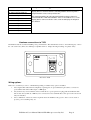
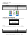
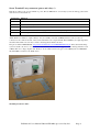
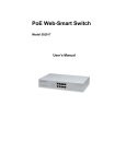
JED MICROPROCESSORS PTY LTD
173 Boronia Rd, Boronia, (PO Box 30), Victoria, 3155, Australia.
Phone: +61 3 9762 3588, Fax: +61 3 9762 5499.
Web site: http://www.jedmicro.com.au email: [email protected]
T470 Users and installation manual, Part A, V039
Ed Schoell Dec 16th, 2015
Introduction
The JED T470 unit is a wall-mounted controller which communicates
with a projector or flat panel via RS232 or IR signalling. (Later
software will enable RS-232 control of a display and IR control of
ancillary equipment (e.g. tuners, players or sound systems).
(Also one (or two) T470(s) will be used as the “head” unit(s) in
combination with the T452 room controller box, which has more relay
connections, four serial ports and other I/O.)
The T470 has an RS232 interface wired to a 5-way Phoenix connector
and a CAT5. Tx and Rx lines only are provided, no handshake lines
are used. If the unit is ordered with the –R2 option (two relay
outputs), the RS232 connection can only be made via the CAT5 cable.
It also has a pin called “Res” which can be used as a PIR (Passive Infra-Red) input, an IR output or a voltage output to
drive an external solid state (directly) or a mechanical relay (via an external FET device).
Power supply
Both connectors also have a ground and a 12 volt input for power supply purposes. This can be unregulated 9 to 15
volts DC, although JED normally supplies the T470 with a small regulated plug pack when sold into the Australian or
New Zealand market. Current consumption is approximately 50mA.
(Connections and wiring to the T470 are covered in the later part of this manual, page 4)
Setting up the T470 in stand-alone mode
To set up the T470 in stand-alone mode, it is necessary to connect the T470 RS232 port to a PC, either directly to a
hardware RS-232 serial port or to a USB -> RS232 connection to the PC.
While more details of wiring the T470 follow, basically the following 3-wire connections are needed. If the T470 does
NOT have the relay option installed, this can be to the Phoenix screw terminals or via a short CAT5 cable.
Function
Phoenix screw
terminals
CAT5 cable
T-568A
Connection to back of female
DB9 to PC or USB-DB9
Ground
Gnd
Solid-Blue and Solid-Brown
Pin 5
RS232 from T470 to PC
Tx
Brown/White
Pin 2
RS232 to T470 from PC
Rx
Blue/White
Pin 3
Unused
Res
+12 volt input
12v
Connect a 12-volt power supply to the T470. Use a multimeter to verify polarity … the white stripe on the power
adaptor cable sometimes indicates –ve, sometime +ve. A hint: strip 5mm of plastic from the wire and fold back once
over the plastic. Open the screw fully, then slide wire AND plastic into the Phoenix screw terminal before tightening the
screw on both. This makes for a stronger termination. It will start up with the red LED above the OFF key lit.
Start the JED T470 Configuration Utility. This can be downloaded from: http://www.jedmicro.com.au/T470.html
A PDF user’s manual for the Configuration Utility is on-line, accessed via the “Help” button.
T470 Part A User’s Manual V039 © JED Microprocessors Pty Ltd
Page 1
Step-through a typical setup sequence
ComPort Setup
Click the down-arrow in the ComPort Setup and then select the active port for the RS232 connection to the T470.
Connect
(Verify that the red LED above the OFF key on the T470 is illuminated.)
Click on the “Connect” button.
The red LED will flash quickly 5 times and the Status window will show a “Controller is now connected” message.
Get Configuration
Clicking on the “Get Config” button will fetch the current T470 configuration.
The “Progress” bar will show this loading, and the “Status” window should show “Config downloaded successfully”.
The current T470 configuration is then shown in all data/status windows:
•
The Current Device code: a 4-digit number in the top setup windows. The current ID is shown in a window,
and is marked as “Invalid Code” if it is not recognised, or during entering codes not recognised so far as digits
are entered. The text window below the four code-setting buttons shows the current target display device;
•
The pre-set Keypad code, in red at the top of the Keypad layout drawing and the default (or pre-loaded) source
allocations to each key are shown.
Note: the keypad code is loaded during manufacture, and is not normally field-alterable. The order/invoice
code used is this keyboard code, with an added letter which identifies the keyboard completely. This gives
labels such as PC, DVD, TV etc to the ones labelled Source1, Source2, Source3 etc ;
•
The Timer settings, either default values (loaded from the internal device data-base) or previously set. These
are the Warm-up Time, the Cool-down Time, and a couple of internal timers, rarely needing adjustment;
•
The RES pin allocation. Choices are: PIR, IR Out, or Relay 3 Out.
In PIR mode, the T460 senses the presence of people in the room (sensing body heat, via IR) If detected, an
internal “PIR Run Timer” is reset repeatedly, and no display device turnoff is triggered. However, if everybody
leaves the room, the PIR Run Timer will timeout after the set time, and the display device is turned off. IN this
mode, the PIR output contact is wired between the RES pin and Ground. It is internally pulled up by a 4k7
resistor in this mode.
In IR Out mode, IR pulses are transmitted from the RES pin on the back of the T470, and assume a positive,
current-limited voltage is pulsed to an external LED (returned to the Ground pin). This can control a display
device or ancillary equipment such as a Set Top Box, DVD player, external IR controlled audio system, etc.
This can be modulated at 38kHz to normal IR-controlled devices, or be unmodulated, e.g. to connect
electrically to a CommBox LCD display (into a special 3.5mm jack socket).
In Relay 3 Out mode, the RES can source a 5 volt signal to an external opto-isolated 240 volt relay, an optoisolated DC relay or a N-channel power FET (e.g. MTD3055, available from JED) (gate to pin, source to
ground, drain as output) as a solid-state relay control device. Commercial 240V AC or 60 volt DC opto-relays
are available from Element 14: see http://www.farnell.com/datasheets/77538.pdf They are made by Opto22,
Gordos, etc and operate with 3.0 volts at 2mA into the internal opto-isolator LED;
•
The PIR Run-Timer value, the time at which a reset to the OFF state occurs if no-one is sensed by the PIR
(Passive Infra-Red) detector wired to the RES pin (only valid/active if the RES Pin allocation is to “PIR” use);
•
The Max Volume window, which defaults to a data-base preset value, but can be altered, if, for instance, a
particular installation has a lower maximum value requirement. (Also, this accommodates the sometimes
incorrect Max Volume setting by some manufacturers). If the projector uses increment/decrement volume
commands (instead of absolute commands) Max Volume is locked at 0;
•
The Reply Mode setting. If “Greyed-out”, Reply Mode is not available for the currently selected display
device. If available, a selection can be made. If set to “Off”, it is turned off.
If set to “On”, the T470 will interrogate the current running state of the display device every 5 seconds, and
will reset itself to the Off state if the display device has assumed the Off state, either because of a time-out or
IR user turn-off. (The point at which this interrogation occurs is marked by a very brief flash of the red LED
every 5 seconds, like a “heart-beat”);
T470 Part A User’s Manual V039 © JED Microprocessors Pty Ltd
Page 2
•
A Relays window, in which the state of 2 or 3 relays are shown, as well as their function allocation. (Relays 1
and 2 are only usable if the –R2 option has been ordered. Relay3 does not need a special order. A relay which
has had an active allocation has its box set to red. An unallocated relay is shown boxed in green.
If a relay application needs two relays (e.g. a screen control function which uses one relay for “Screen Down”
and second one for ‘Screen Up”, the next relay in sequence is allocated automatically. (Relay 3 is only active if
it has been selected as the valid state in the RES pin selection above.)
Set Configuration
As part of the setup process, data can be selected or entered into any of the above windows to suit the particular
installation, and the Set Configuration button clicked to transfer the setup to the T470 currently connected.
Source allocations: Clicking on a “Source Key” will pop up a list of provided source messages by name and by
number 0->F. Any one of these can be selected and “OK” will allocate this, which is then shown below that source key.
One function which updates and displays a Device ID string immediately are the < and > arrows either side of the
Device ID window which will only display valid entries in the device database. After stepping to the desired device,
press “Get Config” which will update the source labels on the keyboard with sources named as appropriate to the new
device code.
(The functions of each of these windows is described in the on-line “Help” at the top left of the config. Utility.)
After changing any selection/value, press “Set Config.” To update the controller, and “Get Config.” To verify the
setting went through correctly (e.g. an invalid code was not attempted to be set.)
Factory Reset (to a phantom/demo/training mode)
Clicking on “Factory Reset” will select a default “phantom” display device, Code: 0000h which is quite useful for demo
and testing purposes. It sets valid English language messages (and a number) for all sources, and when in monitor mode
(see next) will transmit them at 9600 baud. Default times, etc are set up as well. English demo display text also are sent
for volume, blank/mute TV channel change messages, etc.
Monitor button
Clicking on “Monitor” switches to a mode where a serial connection to the T470 is made as if the PC was a display
device and the T470 is reset (Red OFF LED illuminates).
The T470 shows the initial “Power Off” (usually twice) and a “PowerGet” command (used to verify communications,
and used to blink the red LED once (connect) or three times (No connect)
Baud rate, serial format and hex/ASCII mode is set up automatically to suit the data-base settings. ASCII data is shown
in text in blue, and in “ASCII” mode, hex data (such as CR and LF) are shown in red as hex between angled brackets,
e.g. <0D><0A>.
Each received string is placed on its own line with a time stamp. The break delay to a new line is controlled by the
“Break (ms)” window.
The T470 can be operated for a Complete Off press -> On-> run all sources/buttons -> Off cycle.
When finished in “Monitor” mode, press the T470 OFF button and allow it to close down. (Pressing Off and the button
above it simultaneously speeds up the “Closedown” time.) When the red LED is on and stable, click on “Setup” (top
left on monitor screen). Click on “Connect” to re-launch the Configuration Utility.
Update button
NOTE: A software update does NOT change any other settings.
This button allows the software in a T470 to be updated to a newer revision. Firstly the “Open” button should be used to
select the “.hex” file to be used. This file is on the JED web site, T470 page.
Updating is shown on the “progress” bar. The “Firmware Version” window shows a three-digit version number of
current software loaded.
File tab
A configuration can be read from an existing T470, saved under one name, an alteration made and tested,
and then the new configuration saved under a new name.
File tab | Open
This button allows an existing saved configuration for a T470 to be browsed to and opened. The file extension is “.cfg”.
The system will remember the last directory in use, and allows a user-set-up filing system, e.g. by campus, then by
wing, then by classroom.
T470 Part A User’s Manual V039 © JED Microprocessors Pty Ltd
Page 3
File tab | Save
This allows the existing T470 configuration to be saved on disk in a user-set-up filing system.
Help tab
This accesses a pdf help file for the Configuration Utility.
Setting up T470 relay options
Relay drive outputs from the Tx and Rx pins on the green Phoenix connector on the back are available if ordered as the
“-R2” option. These are Solid-state relays (N-channel power FETs), not mechanical (with isolation)
In a stand-alone T470 system (without the –R2 option), Relay 3 option of the RES settings is the only relay function
available.
All three relays in a stand-alone T470 system are set up in the lower-right hand side of the Config Utility. There are
buttons for all relays, and a “clear-all” button. The “Function” window below the buttons shows (in text) the allocated
function of the currently selected relay. If “None” is selected, the relay button is green, and it is red if active. Relay 3 is
dimmed and un-selectable if the RES pin is set other than to “Relay 3 Out”.
Note: If a relay function is set which needs TWO relays (e.g. screen down and screen up on separate relays) then
the next relay numerically is reserved automatically, and an “Unavailable” message shows in the function
window.
The following table shows the functions available for any relay, with an explanation:
Function No / Name
Relay Function / Suggested Use
00: None
Key turns green, no allocation
01: 1 Pulse Down / 1 Pulse Up
Drive screens automatically at Display-device On/Off key activation (or
manually via a “Screen” button) of type which needs a 2-second contact
closure (on the first line to a common ground) to lower the screen, and a
contact closure (on a second line to ground) to raise it. Assumes limit
switches set travel. A “Screen” button can raise or lower the screen at any
time before or during the Display-device on time.
02: 1 Pulse Action / Alt Drive to
Stop
Drive screens automatically at Display-device On/Off key activation of a
type which needs a 2-second contact closure (on the first line to a
common ground) to begin screen-down travel, and a contact closure (on a
second line to ground) to stop downwards travel. To raise the screen, a
contact closure on the second line begins upward travel, and a contact
closure on the first line stops travel. The time of downwards-travel is
automatically set from the display device “Warm-up” constant, and the
screen up-travel time from the “Cool-down” time. These can be set in the
“Timers” window. (No “Screen” button can be used with this type of
screen, as timing is needed.)
03: Pulse Action / 2 Pulses
Together to Stop
Drive screens automatically at Display-device On/Off key activation of a
type which needs a 2-second contact closure (on the first line to a
common ground) to begin screen-down travel, and a contact closure (on
BOTH lines to ground) to stop downwards travel. To raise the screen, a
contact closure on the second line begins upward travel, and a contact
closure on BOTH lines stops travel. The time of downwards-travel is
automatically set from the display device “Warm-up” constant, and the
screen up-travel time from the “Cool-down” time. These can be set in the
“Timers” window. (No “Screen” button can be used with this type of
screen, as timing is needed.)
04: Direct Drive for Warm-up /
Cool- down Duration
Direct control where contact time of first line sets down-travel time and
contact time on second line determines up-travel time. The times are set
by the “Warm-up” and “Cool-down” time settings. (No “Screen” button can
be used with this type of screen, as timing is needed.)
05: 1 Relay Close Down / Open
for Up
Uses one line which closes to drive screen down (and stop with a limit
switch) at Display-device On/Off key activation (or manually via a
“Screen” button). Relay stays on for entire time. Screen travels up when
relay opens, again stopping with limit switch. A “Screen” button can raise
T470 Part A User’s Manual V039 © JED Microprocessors Pty Ltd
Page 4
Function No / Name
Relay Function / Suggested Use
or lower the screen at any time before or during the Display-device on
time.
Note 1: This option can also be used to control functions for power,
lighting, or audio, with automatic or manual actioning.
Note 2: Relay-3 has a voltage output of 5 volts when “On”, which is
compatible with screens needing a “trigger” signal.
09: 1 Pulse Down / 1 Pulse Up
(No automatic)
Drive screens (manually via a “Screen” button) of type which needs a 2second contact closure (on the first line to a common ground) to lower the
screen, and a contact closure (on a second line to ground) to raise it.
Assumes limit switches set travel. The “Screen” button can raise or lower
the screen at any time before or during the Display-device on time.
0a: 1 Relay Close Down / Open
for Up (No automatic)
Uses one line which closes to drive screen down (and stop with a limit
switch) manually via a “Screen” button. Relay stays on for entire time.
Screen travels up when relay opens, again stopping with limit switch. The
“Screen” button can raise or lower the screen at any time before or during
the Display-device on time.
21: On with On press/Off at end
of Cool-down
This is designed to drive a dipper which drops on relay closure and
withdraws on relay open. This allows full cool-down while projector is
descended. Can also be used for system power control (but not display).
22: On with On Press (5 second
display delay / Off at end of
Cool-down
This is designed to control power to the actual display device. Power is
switched on by the relay activation, and then 5 seconds later the ON
command is sent to the display device. The relay deactivates at the end
of cool-down.
23: On with On press/Off with
Off button
This is designed to drive a dipper which can withdraw while projector
cools.
24: On at End Warm-up/Off with
Off button
Relay controls room lighting.
25: On at End Warm-up (Undim
on Blank On)/ Off with Off
Button
Relay controls room lighting, with room lighting returning to normal when
the display is blanked.
30: Momentary Mode, Key A
Relay operates only when key is down, releases when key released. LED
illuminates when key pressed. Can control external devices with
momentary-contact switch input, e.g. a switcher, VC system, etc.
31: Momentary Mode, Key B
32: Momentary Mode, Key C
33: Momentary Mode, Key D
34: Run Toggle Mode Key A
35: Run Toggle Mode Key B
Run Toggle mode (Push On/Push Off) Relay operates only when LED is
lit. Only operates in Run mode. Can be used for a variety of control tasks.
36: Run Toggle Mode Key C
37: Run Toggle Mode Key D
38: Anytime Toggle Mode key A
39: Anytime Toggle Mode key B
Anytime Toggle mode (Push On/Push Off) Relay operates only when LED
is lit. Operates anytime. Can be used for a variety of control tasks.
3a: Anytime Toggle Mode key C
3b: Anytime Toggle Mode key D
3c: Radio mode Key A
3d: Radio mode Key B
3e: Radio mode Key C
3f: Radio mode Key D
A number of keys form a group with “Radio” functions, i.e. press Key A
and the first relay operates and LED lights. Press Key B and the second
relay in the group operates and the second LED lights. Any On relays
release and On LEDs turn off when any other key is pressed. One, two,
three of four Radio keys can be defined. (In a three-relay T470, the fourth
key just turns the other three Off.)
T470 Part A User’s Manual V039 © JED Microprocessors Pty Ltd
Page 5
Function No / Name
Relay Function / Suggested Use
40: Source Key 1 Actioned
Relay operates when defined Source Key is pressed, and stays on while
display device is on that channel. Selecting another source key with a
relay linked to it releases the previous one.
41: Source Key 2 Actioned
42: Source Key 3 Actioned
43: Source Key 4 Actioned
44: Source Key 5 Actioned
This context provides for relay-operated switchers whose channel is
selected with the T470 source buttons. If this is the mode of use, set all
display device sources to be the same, and set to display the output of
the switcher.
45: Source Key 6 Actioned
46: Source Key 7 Actioned
47: Source Key 8 Actioned
48: Source Key 9 Actioned
Hardware connections to T470
JED
T470
Gnd
Tx
Rx
Res
12V
The T470 mounts into standard Aust/NZ power-point hardware. The metal bracket screws to the wall using any or all of
the oval screw holes. (It has slots making it compatible with “C” clamps allowing mounting on a plaster wall.)
8
1
Rear View T470
Wiring options
There are a several ways to wire to a T470 unit depending on whether relay option is installed:
1.
Via a single CAT5 cable. This has simplicity, requiring just one pre-terminated 4-pair cable to connect 12v
power, RS232 and either an IR output or a PIR input;
2.
Via just the 5-way screw terminal connector. This allows a power pair from a plug pack and an RS232 cable
and an extra wire (for IR out or PIR in) to be connected via screw terminals Note: this option cannot be used if
relays are installed.
3.
Via a combination of these two. This is required where the T470 has relay option to drive a screen, audio or
projector power switching relay, etc.
T470 Part A User’s Manual V039 © JED Microprocessors Pty Ltd
Page 6
1. Single CAT5 option (EIA568A)
This allows a pre-terminated cable to be run through a wall to the back of the T470, with all connections via the cable.
We recommend stranded cable
Colours
EIA568A
wire number
Function
Colours
EIA568A
wire number
Function
Green/white
1
+ 12v supply feed via CAT5
Green
2
Gnd (power)
Orange/white
3
Res/IR out/PIR in
Orange
6
N/C
Blue/white
5
RS232 to T470 from projector
Blue
4
Ground to Proj. RS232
Brown/white
7
RS232 from T470 to projector
Brown
8
Ground to Proj. RS232
2. Screw Terminal 5-way connector only option
This allows wiring to the screw terminals of power, RS232 and IR out / PIR in (with nothing connected to the CAT5
connector.)
Connection
Function
Gnd
Ground
Tx
RS232 from T470 to projector
Rx
RS232 to T470 from projector
Res
IR out / PIR in / Relay-3 out
12v
+12 volt input
3. Combination of Screw Terminals and CAT5 option (when screen relay * option
installed)
This mode uses the CAT5 connector for RS232 only … this can be run to the projector directly (with nothing else
connected).
Colours
EIA568A
wire number
Function
Colours
EIA568A
wire number
Function
Green/white
1
N/C
Green
2
N/C
Orange/white
3
N/C
Orange
6
N/C
Blue/white
5
RS232 to T470 from projector
Blue
4
Ground to Proj. RS232
Brown/white
7
RS232 from T470 to projector
Brown
8
Ground to Proj. RS232
T470 Part A User’s Manual V039 © JED Microprocessors Pty Ltd
Page 7
Screw Terminal 5-way connector (power and relays *)
This allows wiring to the screw terminals of power, IR out / PIR and two screen relays (for Down and Up pulses at the
start and end of a lecture/show)
Connection
Function
Gnd
Ground
Tx
Screen Down Relay drive *
Rx
Screen Up Relay drive * OR unmodulated IR (0->5V) out to CommBox LCD
Res
IR out to an IR transmitter LED (to ground) / PIR contact input (to ground) / Relay-3 FET drive **
12v
+12 volt input
*Note: While we call these outputs “Relays” they are actually solid state (N-FET) transistors whose Source is
connected to the common Ground of the system and Drain to the output terminal. When OFF they are high impedance,
and when ON are like a closed relay contact connecting the terminal to Ground.
The part is called an MTD3055VL: http://www.fairchildsemi.com/ds/MT/MTD3055VL.pdf It has an internal clamp
system set at 60 volts, and so does not need an external Zener diode transient suppressor when driving inductive loads.
**Note: This is a voltage output in this “Relay-3” mode which can drive the gate of an N-FET (such as a MTD3055VL) This FET is external to the T470 device.
Mounting bracket for T470
T470 Part A User’s Manual V039 © JED Microprocessors Pty Ltd
Page 8