1
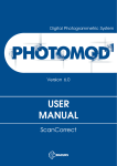
FiveBOT003 Omni 3 Wheel Drive Robotic Platform
Installation
Quick Start Guide
Fivebro International Corp.
User Manual V1.2
Table of Contents
1.
2.
3.
4.
5.
6.
FB003 Robotic Platform Overview…………………………………………. 2
FB003 Omni 3WD Parts List…………………….………………………….. 3
FB003 Electronic Components...…………………………………………… 4
FB003 Omni 3WD Chassis Construction……………………………........ 5
Sample Wiring Installation………………………………………………… 19
Arduino Control Board and Sample Code……….………………………… 21
i.
Introduction……………….………………………………. 21
ii.
Specification……………………………………………... 22
iii.
Arduino control board layout………………………….. 23
iv.
Arduino control board pin jumpers……………………. 24
v.
Powering the Arduino control board………………….. 25
vi.
Uploading sample code to the Arduino control board 26
vii.
Tutorials…………………………………………………… 30
viii.
Sample Code 1………………...………………….......... 30
ix.
Sample Code 2………………...………………………... 31
x.
Dual DC Motor Speed Control…………………............. 31
xi.
Sample code 3: Standard PWM DC control………….… 32
xii.
IO Expansion Board…………………….…………………34
7. Limited Warranty……………………………………………………..………. 35
Version History
(mm/dd/yyyy)
v1.0 – 08/24/2010 – Author: JY, sample code v1.0
v1.1 – 03/07/2011 - Authors: AJ, KL, EC sample code v1.0
v1.2 – 03/16/2011 – Author: AJ, Updated: New components.
1. FB003 Robotic Platform Overview
This manual will explain how to assemble and configure your FiveBOT robot. Please
take your time to carefully read through this manual.
The FiveBOT003 Omni-3 wheel robotic platform robotic platform is designed for
researchers and students working on robotic development. FiveBOT003 Omni-3 wheel
robotic platform has vast advantages over a conventional robot designs as it has better
mobility in congested environments. It is capable of easily performing tasks in
environments congested with static and dynamic obstacles and narrow aisles.
FiveBOT003 Omni-3 Wheel robotic platform comes with 3 Omni-directional wheels
controlled by 3 DC motors, allowing rotation and movement in any direction
simultaneously. The robotic platform’s 3 Ultrasonic Sensors allow the FB003 to avoid
obstacles in 360 degrees.
The FiveBOT003 robotic platform’s maximum load capacity is 15kg. This load can
be placed on top of the platform.
Fivebro International Corp.
2
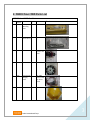
2. FB003 Omni 3WD Parts List
FB3003 Omni 3WD Part List
ID
Part Name
QTY
1
Part
Number
12003
Battery
Mounting
Plate
1
2
95002
Hex
Screwdrivers
1
3
16002
DC Motors
3
4
14056
Omni Wheels 3
5
12040
Power Switch 1
Charging
Socket
6
12025
Omni Chassis 1
Accessories
Check
4 piece set
With
encoders and
cables
One Main
Power switch,
One Power
switch
Fivebro International Corp.
3
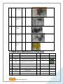
7
80009
Wheel Hub
Screws Bag
1
8
80014
M4 * 8 Hex
Socket Head
Cap Screw
6
9
12016
Ultrasonic
Rubber
Grommet
6
10
18005
Wheel Hub
Assembly
3
11
12030
Second Layer 1
Mounting
Plate
3. FB003 Omni 3WD Electronic Components
ID
Part Number
Part Name
QTY
Accessories
1
22002
Arduino Board, Atmega328
1
Screws
2
22004
Arduino Expansion V1.1
1
3
20012
Dual Ultrasonic Sensor Module
3
4
76001
NI-MH Battery 12V 1800mAh
1
5
76002
NI-MH Battery Charger, 500mA
1
6
71001
Motor Encoder Cable
3
7
71005
Arduino USB Cable
1
8
71006
Jumper Cable
2
9
80011
Ultrasonic Cable & Screws
3
10
80008
Controller Screws Bag
1
Fivebro International Corp.
Check
Cable, Screws
4
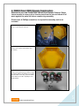
4. FB003 Omni 3WD Chassis Construction
Welcome to your new FiveBOT004 2 Wheel Drive Robotic Platform! Please
take a moment to remove all of chassis parts from the box and check all of
parts against the parts list before commencing assembly.
Please note: A Phillips screwdriver is required for assembly and is not
included.
Step 1. Check all parts and tools.
Step 2. Take out the Omni chassis (Part
No:12025)
Step 3. Take out the three DC Motors (Part
No:16002) and the small black screws from
the wheel hub screws bag (Part No:80009).
These black screws have a phillips (crossshaped) head.
Fivebro International Corp.
5
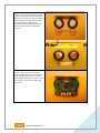
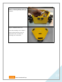
Step 4.Place the DC Motors into the holes in
the Omni chassis as shown.
Please ensure that the DC motors are placed
in the correct orientation with the green
encoder boards facing upwards (as shown to
the right).
Step 5. Use each of the screws from Step 3
to secure the DC motors into the Omni
Chassis. Please be sure to tighten each
screw a little, one at a time as shown in the
diagram using a Phillips screwdriver.
Please double check to ensure the DC motor
is secured flush to the inside wall of the
chassis. If it is not, you need to tighten
these screws the whole way.
Fivebro International Corp.
6
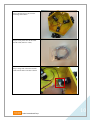
Step 6. Take out the couplers from the
wheel hub assembly bag (Part No: 18005).
Also take out the silver Phillips-head screws
from the wheel hub screws bag (Part No:
80009).
Step 7. Place one of the couplers onto one of
the DC Motor shafts as shown.
Step 8. Place four of the silver screws from
step 6 into one the coupler as shown.
Secure the screws using a Phillips
screwdriver.
Fivebro International Corp.
7
Step 9. Repeat step 8 for the two remaining
couplers.
Step 10. Take out the small hexagonal
black screws from the wheel hub screws bag
(Part No: 80009). Use the smallest sized
hexagonal screwdriver (pictured) to secure
these screws onto the couplers.
Step 11. Take out the three Omni Wheels
(Part No:14056). Also take out the large
hexagonal screws and wheel hubs from the
wheel hub assembly bag (Part No:80009).
Fivebro International Corp.
8
Step 12. Place one of the Omni wheels onto
the couplers as shown.
Step 13. Place a wheel hub onto the Omni
wheel as shown.
Step 14. Take out one of the large
hexagonal screws from the wheel hub
assembly bag (Part No:80009) and use the
largest hexagonal screwdriver to secure
them on as shown. Please ensure the two
washers included are also screwed on.
Fivebro International Corp.
9
Step 15. Repeat steps 12 to 14 for the
remaining Omni wheels.
Step 16. Next please take out the motor
encoder cable (Part No: 71001).
Step 17. Plug each of the motor encoder
cables into the motor encoders as shown.
Fivebro International Corp.
10
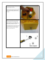
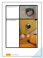
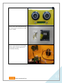
Step 18. Next, take out the power switch
and charging socket (Part No: 12040).
Step 19. Set up the charging socket as
shown in the following two images.
Fivebro International Corp.
11
Step 20. Install the power switch as shown
in the following two images.
Step 21. Connect the charging socket and
power switch by joining the smallest set of
white plugs (pictured).
Fivebro International Corp.
12
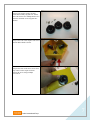
Step 22. Take out the following parts:
Ultrasonic rubber grommet (Part No:
12016)
Dual Ultrasonic Sensor Module (Part No:
20012)
Step 23. Place all 6 of the ultrasonic rubber
grommets (Part No: 12016) into the holes
around the chassis.
Fivebro International Corp.
13
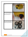
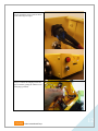
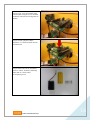
Step 24. Take out the small bronze colored
spacers from the packet labeled Ultrasonic
Cable & Screws (Part No: 80011) and fasten
them to the inside of the chassis as shown.
Use the small silver Phillips screws
contained within the same bag and screw
them in from the outside of the chassis
(pictured).
Step 25. Take out the Dual Ultrasonic
Sensor Module (Part No: 20012) and place
it into the rubber grommets. Secure the
sensor module using the silver screws from
the Ultrasonic Cable & Screws Bag (Part
No: 80011).
Fivebro International Corp.
14
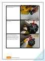
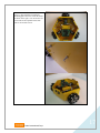
Step 26. Take out the Arduino Board (Part
No: 22002) and the Controller Screws Bag
(Part No: 80008).
Step 27. Fasten the bronze colored pillars
onto the chassis using the small screws
contained the same bag.
Fivebro International Corp.
15
Step 28. Next, secure the Arduino board
onto the pillars using the screws contained
within the Controller Screws Bag (Part No:
80008).
Step 29. Finally, plug the Arduino
Expansion V1.1 (Part No:22004) into the
Arduino board.
Step 30. Please take out the 12V Battery
(Part No. 76001) , the Battery Mounting
Plate (Part No. 12003) and its
accompanying screws.
Fivebro International Corp.
16
Step 31. Place the battery beneath the
mounting plate and screw it into the chassis
as shown to the right. You will need to use
a screwdriver and a spanner at the same
time to secure these screws.
Fivebro International Corp.
17
Step 32. Connect the charging socket to the
battery by connecting the large white plug
as shown.
Step 33. Install the chassis cover.
Your chassis building is now complete!.
Please read the following section for
instructions on how to connect the
remaining wires in the chassis.
Fivebro International Corp.
18
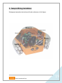
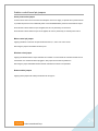
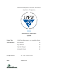
5. Sample Wiring Installation
Subsequent assembly instructions will make references to this figure.
Fivebro International Corp.
19
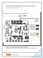
The diagram below illustrates an example of how to connect the Arduino control board to the
sensors, motors and battery. Please pay particular attention to the battery connections. Wiring
these incorrectly will cause damage to the controller.
Please see the following page for expansion board connections.
Fivebro International Corp.
20
6. Arduino Control Board & Sample Code
A. Please read this section carefully before applying power to the Arduino control board.
B. The control board is not designed for military or medical purposes and therefore cannot be used for these
applications.
C. The FB004 2WD sample code can be found on this user guide, on the accompanying CD and also under
the support section of the Fivebro International website – www.fivebro.com.tw.
Introduction
The FB003’s Arduino control board is a specially modified Arduino control board designed especially for
robotics applications. Built from the Arduino open source platform, it is supported by thousands of open
source codes and can be easily expanded with most Arduino Shields. The integrated 2 way DC motor driver
and wireless socket gives you a much easier way to start your robotic project.
Fivebro International Corp.
21
Specification
Atmega328P microcontroller
14 Channels Digital I/O
6 PWM Channels (Pin11,Pin10,Pin9,Pin6,Pin5,Pin3)
8 Channels 10-bit Analog I/O
USB interface
Auto sensing/switching power input
ICSP header for direct program download
Serial Interface TTL Level
Supports AREF
Supports Male and Female Pin Header
Integrated sockets for APC220 RF Module
Five IIC Interface Pin Sets
Two way Motor Driver with 2A maximum current
7 key inputs
DC Supply:USB Powered or External 7V~12V DC。
DC Output:5V /3.3V DC and External Power Output
Dimensions:90x80mm
Fivebro International Corp.
22
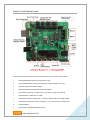
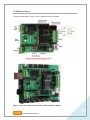
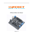
Arduino Control Board Layout
The picture above shows all of the I/O lines and Connectors on the controller, which includes:
One Regulated Motor Power Input Terminal (6v to12v)
One Unregulated Servo Power Input Terminal (you supply regulated 4v to 7.2v)
One Servo input power selection jumper
One Serial Interface Module Header for APC220 Module
Two DC Motor Terminals – Handles motor current draw up to 2A, each terminal
One IIC/TWI Port – SDA, SCL, 5V, GND
One Analog Port with 8 analog inputs – one input is tied internally to the supply voltage
One General Purpose I/O Port with 13 I/O lines – 4,5,6,7 can be used to control motors
One Reset Button
Jumper bank to Enable/Disable Motor Control
Fivebro International Corp.
23
Arduino control board pin jumpers
Servo power select jumper
As most servos draw more current than the USB power source can supply, a separate servo power terminal
is provided to power the servo individually which can be Enable/Disable by the Servo Power Select Jumper.
When the Servo Power Select Jumper is applied, the servo is powered by an internal 5V.
When the Servo Power Select Jumper is not applied, the servo is powered by an external power source.
Motor control pin jumper
Applying the Motor Control Pin Jumpers will allocate Pins 4, 5, 6 and 7 for motor control.
Removing the jumpers will release the above pins.
Wireless select jumper
Applying the Wireless Select Jumper will allow the controller to communicate via a wireless module such as
the APC220. If no wireless module is plugged in, this jumper will not make any difference.
Removing the jumper will disable wireless module and allows the sketch to be uploaded.
Button enable jumpers
Applying these jumpers will enable push buttons S1 through S7.
Fivebro International Corp.
24
Powering the Arduino control board
Applying power
This is one of the most important steps in getting your control board up and communicating with your host
controller. Your control board can be powered from its USB port (connected to your computer), from its
motor power input or from its servo power input. Power from the USB port will provide the control board with
enough power to upload and run sketches, but not enough power to drive servos or DC motors; for these
applications, power from the servo power input or the motor power input is required.
Please note: When applying power to either the Motor Power Input or the Servo Power Input, please ensure
you use the correct polarity. Reverse Polarity will damage the controller. We are not responsible for such
damage, nor does our warranty cover such damage. Please make sure you take time to apply the power
correctly!
Power from the servo power Input:
Connect the battery to the Servo Power Input. You MUST make sure that you apply power to the Power
Terminal using the correct polarity (refer to “Arduino control board Layout” on page 23).
Power from motor power input: Connect the battery to the Motor Power Input. You MUST make sure that
you apply power to the Power Terminal using the correct polarity (refer to “Arduino control board Layout” on
page 23).
From USB: Simply connect your control board to your computer via USB cable, and the controller is able to
work. Please note that the USB can supply a maximum current of 500 mA. It should be able to meet the
most requirements for LED applications, however it is not enough to power servos or DC motors.
Fivebro International Corp.
25
Uploading sample code to the Arduino control board
For this section you will need:
Arduino IDE (Integrated Development Environment) software
The FB004 sample code
The Arduino IDE (Integrated Development Environment) is a piece of software that allows you to write
programs on your computer and then upload them onto the Arduino control board. The control board
included in this package can be programmed using Arduino IDE version 0014 and above. It is included on
the CD but can also be downloaded directly from the Arduino website at http://arduino.cc/en/Main/Software.
You will also need the FB004 2WD sample code file. It is located on the accompanying CD and it is also
supplied on the Fivebro international website (http://www.fivebro.com.tw) under the support section.
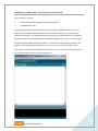
Once you have downloaded and extracted both of these files, you can execute the file named “arduino.exe”
and you will be presented with a screen that looks like this:
Fivebro International Corp.
26
The next step is to simply connect the Arduino control board to your computer using the USB cable supplied
(part #71005).
Please note: The Arduino expansion board cannot be plugged in while uploading any programs.
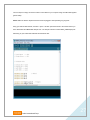
Using your Arduino IDE software, click File > Open > and then point the browser to the location where you
have downloaded the FB004 2WD sample code. The sample code file is called “FB004_2WDSample.pde”.
After doing so your Arduino IDE software should look like this:
Fivebro International Corp.
27
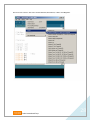
Now click Tools > Board > then select “Arduino Diecimila, Duemilanove, or Nano w/ ATMega328”.
Fivebro International Corp.
28
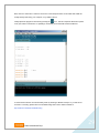
Next, click File > Serial Port > and then choose one of the serial ports listed. Ports COM1 and COM2 are
usually already reserved by your computer, so try COM3 or above.
Finally upload the program to the board by pressing the
icon. This will compile the sketch and upload
it into your Arduino control board. If uploading is successful your Arduino IDE should look like this:
If communication with the control board fails, please try selecting a different serial port. If you still cannot
succeed in connecting, please refer to the troubleshooting section of the Arduino website at:
http://arduino.cc/en/Guide/Troubleshooting
Fivebro International Corp.
29
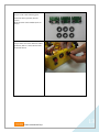
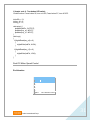
Tutorials
Button Press Tutorials
The controller has 7 build-in buttons, labelled S1-S7. Buttons S1-S5 use analog input, S6, S7 use digital
input.
To enable S6 and S7, apply all three of the “button enable jumpers” (shown on the layout diagram, page 23).
S6 uses Digital Pin2, S7 uses Digital Pin3. Once these enable jumpers have been applied, Pin 2 and 3 will
be occupied by the push buttons.
// Sample code 1: One-button LED switch
//Code function: Press button S6, LED turns on, press it again, LED turns off.
int ledPin = 13;
int key_s6 = 2;
int val=0;
void setup()
{
pinMode(ledPin, OUTPUT);
// Set Pin13 to output mode
pinMode(key_s6, INPUT);
// Set Pin12 to output mode
}
void loop()
{
if(digitalRead(key_s6)==0) {
while(!digitalRead(key_s6));
val++;
}
if(val==1) {
digitalWrite(ledPin, HIGH); //
}
if(val==2) {
val=0;
digitalWrite(ledPin, LOW);
}
//
}
Fivebro International Corp.
30
// Sample code 2: Two-button LED switch
//Code function: Press button S6, turn on LED, Press button S7, turn off LED.
int ledPin = 13;
int key_s6 = 2;
int key_s7 = 3;
void setup() {
pinMode(ledPin, OUTPUT);
pinMode(key_s6, INPUT);
pinMode(key_s7, INPUT);
}
void loop()
{
if(digitalRead(key_s6)==0)
{
digitalWrite(ledPin, HIGH);
}
if(digitalRead(key_s7)==0)
{
digitalWrite(ledPin, LOW);
}
}
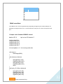
Dual DC Motor Speed Control
Pin Allocation
"PWM Mode"
Pin
Function
Digital 4
Motor 1 Direction control
Digital 5
Motor 1 PWM control
Digital 6
Motor 2 PWM control
Digital 7
Motor 2 Direction control
Fivebro International Corp.
31
"PLL Mode"
Pin
Function
Digital 4
Motor 1 Enable control
Digital 5
Motor 1 Direction control
Digital 6
Motor 2 Direction control
Digital 7
Motor 2 Enable control
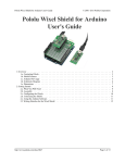
PWM Control Mode
The PWM DC motor control is implemented by manipulating two digital IO pins and two PWM pins. As
illustrated in the diagram above, Pin 4,7 are motor direction control pins, Pin 5,6 are motor speed control
pins.
// Sample code3: Standard PWM DC control
#define LED 13
//pin for the LED labelled "L"
//motor control pins
unsigned char E1=6;
unsigned char E2=5;
unsigned char M1=4;
unsigned char M2=7;
int incomingByte = 0; // for incoming serial data
void setup() {
Serial.begin(9600);
}
void advance() //advance
{
analogWrite(E1,100);
digitalWrite(M1,HIGH);
analogWrite(E2,100);
digitalWrite(M2,HIGH);
return;
}
void back_off () //Move backward
{
analogWrite (E1,100);
digitalWrite(M1,LOW);
analogWrite (E2,100);
digitalWrite(M2,LOW);
Fivebro International Corp.
32
}
void stop() //stop
{
analogWrite(E1,0);
digitalWrite(M1,HIGH);
analogWrite(E2,0);
digitalWrite(M2,HIGH);
return;
}
void loop() {
if (Serial.available() > 0) {
// read the incoming byte:
incomingByte = Serial.read();
// say what you got:
Serial.print("I received: ");
Serial.println(incomingByte, DEC);
if (incomingByte == 119) { // press "w"
advance();
delay(1000);
stop();
}
if (incomingByte == 115) { //press "s"
back_off();
delay(1000);
stop();
}
}
}
Fivebro International Corp.
33
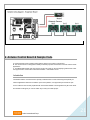
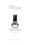
IO Expansion Board
To support RS485 interface or drive 4 motors, IO Expansion Board is available.
Arduino main controller board combine with expansion board
Fivebro International Corp.
34
6. Limited Warranty
FIVEBRO ONE YEAR LIMITED WARRANTY
Fivebros warranty obligations for this FiveBOT (this “Product”) are limited to the terms set forth below.
Fivebro International Corp. (“Fivebro”) warrants to the original end-user purchaser that this Product will be free from defects in
materials and workmanship under normal use for a period of 180 days from the date of retail purchase (the “Warranty Period”).
This warranty is extended only to the original end-user purchaser of a new product that was not sold “as is”.
If a defect arises:
(1) you may within 1 year from the date of retail purchase (or such other period specified by the return policies of the place of purchase)
return this Product to the place of purchase, together with the original proof of purchase and either the original box or the UPC code label
from the box, and this Product will be replaced or, in the event that a replacement for this Product is not available at the place of purchase,
either a refund of the purchase price for this Product or an store credit of equivalent retail value will be provided; or
(2) you may after the day that is 30 days from the date of retail purchase (or such other period specified by the return policies of the place
of purchase) and within the Warranty Period contact Fivebro Customer Support to arrange for the replacement of this Product. In the event
that a replacement for this Product is not available this Product will be replaced by Fivebro with a product of equivalent or greater retail
value.
A purchase receipt or other proof of the date of retail purchase is required in order to claim the benefit of this warranty.
If this Product is replaced, the replacement product becomes your property and the replaced Product becomes Fivebros
property. If the place of purchase refunds the purchase price of this Product or issues a store credit of equivalent retail value, this Product
must be returned to the place of purchase and becomes Fivebros property.
EXCLUSIONS AND LIMITATIONS
This warranty covers the normal and intended use of this Product. This warranty does not apply: (a) to damage caused by
accident, abuse, unreasonable use, improper handling and care or other external causes not arising out of defects in materials or
workmanship; (b) to damage caused by power line surge, lightning or acts of God; (c) to damage caused by service performed by
anyone who is not an authorized representative of Fivebro; (d) to any hardware, software or other add-on components installed
by the end-user; (e) if this Product has been disassembled or modified in any way; (f) to faulty installation or set-up adjustments;
(g) to consumable parts, such as batteries, unless damage has occurred due to a defect in materials or workmanship; (h) to
cosmetic damage, including but not limited to scratches, dents or broken plastic, or normal wear and tear. Regardless of whether
the camera is in use or not,exposure to extremely bright lights or objects can damage the CMOS camera sensor. This warranty
specifically excludes any damage to the CMOS sensor resulting from exposure to extremely bright lights or objects, whether
accidental or deliberate.
THIS WARRANTY GIVES YOU SPECIFIC LEGAL RIGHTS AND YOU MIGHT ALSO HAVE OTHER RIGHTS THAT VARY FROM STATE
TO STATE. FIVEBROS RESPONSIBITLITY FOR PRODUCT DEFECTS IS LIMITED TO THE REPLACEMENT OF THIS PRODUCT OR
THE REFUND OF THE PURCHASE PRICE FOR THIS PRODUCT. ALL EXPRESS AND IMPLIED WARRANTIES, INCLUDING BUT NOT
LIMITED TO ANY IMPLIED WARRANTIES AND CONDITIONS OF MERCHANTABILITY AND FITNESS FOR A PARTICULAR PURPOSE,
ARE LIMITED IN TIME TO THE TERM OF THIS LIMITED WARRANTY. NO WARRANTIES, WHETHER EXPRESS OR IMPLIED, WILL
APPLY
AFTER THE EXPIRATION OF THE LIMITED WARRANTY PERIOD. If any term of this warranty is held to be illegal or unenforceable,
the legality or enforceability of the remaining terms shall not be affected or impaired.
EXCEPT AS PROVIDED IN THIS WARRANTY AND TO THE EXTENT PERMITTED BY LAW, FIVEBRO IS NOT RESPONSIBLE FOR
DIRECT, SPECIAL, INCIDENTAL OR CONSEQUENTIAL DAMAGES HOWSOEVER CAUSED RESULTING FROM BREACH OF
WARRANTY
OR CONDITION OR UNDER ANY OTHER LEGAL THEORY, INCLUDING BUT NOT LIMITED TO LOSS OF USE. THE FOREGOING
LIMITATION SHALL NOT APPLY TO DEATH OR PERSONAL INJURY CLAIMS, OR ANY STATUTORY LIABILITY FOR INTENTIONAL
AND
GROSS NEGLIGENT ACTS AND/OR OMISSIONS.
SOME STATES DO NOT ALLOW THE EXCLUSION OR LIMITATION OF INCIDENTAL OR CONSEQUENTIAL DAMAGES, OR
LIMITATIONS ON HOW LONG AN IMPLIED WARRANTY LASTS, SO THESE LIMITATIONS MIGHT NOT APPLY TO YOU.
Valid only in R.O.C. and U.S.A.
Fivebro International Corp.
35
Manufactured and distributed by 2010-2011 Fivebro International Corp.
Product names, designations, and logos are trademarks or registered trademarks
of Fivebro International Corp. All right reserved.
Fivebro International Crop.
1105 Room, 11F, No. 206, Song Jiang Rd.,
Taipei City 10467, Taiwan, R.O.C.
Email: [email protected]
Web: www.fivebro.com.tw
Customer service line: +886 2 2562 8445
Customer online support: http://www.fivebro.com.tw/supprot/support.html
We recommend that you retain our address for future reference.
Product and colors may vary.
Printed in Taiwan.
This product is not suitable for children under 3 years
This user manual should be kept as it contains important information.
Fivebro International Corp.
36