1
Safety Precautions
Before handling the product
Safety Precautions is for using the product safe and correct in order to prevent the
DATASHEET
accidents and danger, so always follow the instructions..
The precautions explained here only apply to MasterLogic-200 Series.
For safety precautions on the PLC system, refer to FEnet I/F User’s manual.
Read this data sheet carefully prior to any operation, mounting, installation or
start-up of the product.
Materials for MasterLogic-200
The precautions are divided into 2 sections, ‘Warning’ and ‘Caution’. Each of the
Name
meanings is represented as follows.
MasterLogic-200
Warning
Fast Ethernet I/F Module
Caution
If violated instructions, it may cause death, fatal injury or a
considerable loss of property.
If violated instructions, it may cause a slight injury or a slight
loss of products.
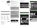
3. Performance Specification
Item Code
2MLK-CPUH/CPUS
Following presents performance specification of Fast Ethernet module.
Performance spec.
Items
100BASE-FX
10/100BASE-TX
Speed
10310000648
MasterLogic-200 BASIC NSTRUCTION
10310000649
MasterLogic-200 SOFTWARE
10310000650
Max. extended
distance of Stationto-Station
Max. Segment
Length.
The symbols which are indicated in the PLC and User’s Manual mean as follows.
2MLL-EFMT
2MLL-EFMF
Give warnings and cautions to prevent from risk of injury, fire, or malfunction.
Name
Give warnings and cautions to prevent from risk of electric shock.
Code
Fast Ethernet(FEnet I/F) I/F Module datasheet
10310000652
Transfer
Spec.
Store this datasheet in a safe place so that you can take out and read whenever
necessary. Always forward it to the end user
Revision History
Warning
X
Publication
Version
2005. 11
V1.0
The first edition
2006. 1
V1.1
Fiber-Optic Module(2MLL-EDMF) is added.
Do not contact the terminals while the power is applied.
Description
Risk of electric shock and malfunction.
X Do
Max. Node No.
Basic
Spec
not charge, heat, short, solder and break up the battery.
10/100Mbps
Base Band
2km
-
100m
(Node-Hub)
Able to link to 9
30
hub stages
Nodes/Segment
(Recommended)
Multiple of 0.5m
1,500 Byte
Node Interval
Max. Protocol Vol.
Excess Method of
Communication
Range
Frame Error Check
CRC16 = X + X14 + X13+ ... + X2 + X + 1
Number of Max.
Installation module
12
Base
not drop or insert any metallic object into the product.
Risk of fire, electric shock and malfunction.
X Do
100Mbps
Transfer System
CSMA/CD
15
Basic and Expansion base
Power Consumption
600
410
Weight (g)
110
105
Risk of injury and fire by explosion and ignition.
4. Cable specification
Caution
X Ensure
10310000652 Printed in Korea
` 10/100BASE-TX(UTP)
to check the rated voltage and terminal arrangement for the
module before wiring work.
Risk of electric shock, fire and malfunction.
X Tighten
the screw of terminal block with the specified torque range.
Risk of fire and electric shock if the terminal screw looses.
X Use
1. Introduction
configurations, and operating of MasterLogic-200 PLC Fast Ethernet I/F module
Risk of electrical shock, fire, erroneous operation and deterioration of the PLC.
that external load do not exceed the rating of output module.
Risk of fire and erroneous operation.
Japan
Honeywell Inc.
Phone: (81)3-5440-1395
Fax: (81)3-5440-1368
Singapore
Honeywell Pte Ltd.
Phone: (65) 6355-2828
Fax: (65) 6445-3033
China
Honeywell (Tianjin) Ltd. – Beijing
Phone: (86-10) 8458-3280
Fax: (86-10) 8458-3102
South Korea
Honeywell Co., Ltd.
Phone : (82) 2-799-6114
Fax : (82) 2-792-9015
Thailand
Honeywell Systems Ltd.
Phone: (662) 693-3099
Fax: (662) 693-3085
Honeywell (Tianjin) Ltd. – Shanghai
Phone: (86-21) 6237-0237
Fax : (86-21) 6237-3102
Malaysia
Honeywell Engineering Sdn Bhd.
Phone: (603) 7958-4988
Fax: (603) 7958-8922
Taiwan
Honeywell Taiwan Ltd.
Phone: (886) 2-2245-1000
Fax: (886) 2-2245-3241
New Zealand
Honeywell Ltd.
Phone: (64-9) 623-5050
Fax: (64-9) 623-5060
For Countries (SE Asia) Listed
below, call Honeywell Singapore
Office
Pakistan, Cambodia, Laos,
Myanmar, Vietnam and East Timor
Indonesia
PT Honeywell Indonesia
Phone : (62) 21-535-8833
Fax : (62) 21-5367-1008
India
Honeywell Automation India Ltd.
Phone: (91) 20-5603-9400
Fax: (91) 20-5603-9800
Philippines
Honeywell Systems Inc.
Phone: (63-2) 633-2830
Fax: (63-2) 638-4013
For Countries Listed below,
call Honeywell India Office
Bangladesh, Nepal, and Sri Lanka
not use the PLC in the environment of direct vibration
Risk of electrical shock, fire and erroneous operation.
X Do
not disassemble, repair or modify the PLC.
Honeywell Process Solutions
17F, Kukje Center Building, 191 Hangangro-2ga,
Yongsan-gu, Seoul 140-702, Korea
Tel : 82-2-799-6114 / Fax : 82-2-792-9015
3
4
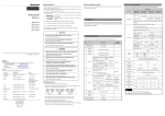
X Do not install in any places other than PLC controlled place.
X Ensure that the FG terminal is grounded with class 3 grounding which is dedicated
to the PLC. Otherwise, it may cause disorder or malfunction of PLC
PLC
Others
< Good >
Voltage resistance
V/min
AC 500
Characteristic impedance
Ω(1~100MHz)
100 ± 15
dB/100m
or less
Decrement
5 ~ 95%RH, non-condensing
PLC
Vibration
6
Shocks
Others
< Bad >
X Connect expansion connector correctly when expansion module are needed,
X Do not detach PCB from the case of the module and do not modify the module.
X Turn off the power when attaching or detaching module.
X Cellular phone or walkie-talkie should be farther than 30cm from the PLC
X Input signal and communication line should be farther than minimum 100mm from a
high-tension line and a power line in order not to be affected by noise and magnetic
field.
non-condensing
7
Noise
immunity
Acceleration
8
9
10
11
Atmosphere
Altitude for
use
Pollution
degree
Cooling
method
Sweep
count
Amplitude
10≤f∠57 Hz
0.075 mm
57 ≤f≤150 Hz 9.8 ㎨ {1G}
10 times in
Continuous vibration
each
Frequency
Acceleration Amplitude direction for
X, Y, Z
10≤f∠57 Hz
0.035 mm
57≤f≤150 Hz 4.9 ㎨{0.5G}
*Maximum shock acceleration: 147 ㎨ {15G}
*Duration time :11 ms
*Pulse wave: half sine wave pulse
( 3 times in each of X, Y and Z directions )
Square wave
±1,500 V
impulse noise
Electrostatic
Voltage :4kV(contact discharge)
discharge
Radiated
27 ~ 500 MHz, 10 V/m
Electromagnetic
field
Digital,
Severity All power
Analog I/Os
Fast transient
Level
modules
communications
burst noise
Voltage
2 kV
1 kV
Free from corrosive gases and excessive dust
Up to 2,000m
2 or lower
Self-cooling
dB/100m
or less
10MHz
6.5
16MHz
8.2
20MHz
9.3
10MHz
47
16MHz
44
20MHz
42
Attenuation
SC type
PC Polish
APC Polish
Less than -45dB,X=-47dB Less than -45dB,X=-47dB
Connection Loss
Less than 0.5dB ,X=0.2dB
Connection Durability
Less than 0.2dB
Less than ±0.2dB
(-40°C ~ +75°C)
Item
Occasional vibration
Precautions for use
Others
2500
` Fiber Optic(100Mbps)
-25 ~ 70℃
5 ~ 95%RH,
Value
Standard
0 ~ 55℃
Frequency
5
PLC
Specification
disposing of PLC and battery, treat it as industrial waste.
Email : [email protected]
10310000652 Printed in Korea
Item
Operating
temperature
Storage
temperature
Operating
Humidity
Storage
humidity
Risk of poisonous pollution or explosion.
< Best >
Honeywell Co., Ltd.
1
2
Risk of electrical shock, fire and erroneous operation.
X When
MΩ·km
Near-end crosstalk
decrement
2. General Specifications
No.
For more information on MasterLogic PLCs , contact your nearest Honeywell office
Australia
Honeywell Ltd.
Phone : (61) 2-9353-4500
Fax : (61) 2-9353-7677
93.5
Insulation resistance(Min)
(FEnet I/F module).
specifications contained in this datasheet.
X Do
Unit
Ω/km
This data sheet contains the brief information about the characteristics,
the PLC in an environment that meets the general
X Ensure
Item
Conductor resistance(Max)
Operating Temp.
IEC61131-2
* 2 core multimode: 62.5/125 fiber optic cable
* Connector: SC type
IEC61131-2
Remark
1) Connecting cable for communication module is different from system
configuration and environment. So, consult with expert before the
installation.
IEC61131-2
IEC61000-4-2
IEC61131-2
IEC61000-4-3
IEC61131-2
IEC61000-4-4
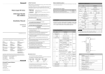
5. Parts Name and Descriptions
Max. segment length of 10/100BASE-TX is 100m(between this module and
the hub). Generally the straight cable is used which is made as twisted with TD
and RD inside. If only 2 communication modules are connected 1 to 1, the
cross cable type shall be applied.
` 2MLL-EFMT/2MLL-EFMF
2MLL-EFMT
HS
P2P
PADT
PC
ERR
2MLL-EFMF
RUN
I/F
TX
RX
10/100
HS
P2P
PADT
PC
ERR
▶ LED Display
RUN
I/F
TX
RX
PHY
Signal
name
TD+
TDRD+
RDN/A
Pin No.
1
2
3
6
4, 5, 7, 8
1:1 cross cable
1—3
2—6
3—1
6—2
` Pin diagram for RJ-45 UTP Jack
Refer to the following pin number for Ethernet cable connection using UTP
RJ-45 connector.
To make the cable, use RJ-45 (cutter and stripper hand tool for RJ-45) and
when it completed, check the wiring and contact with wiring check inspector if
the connection is right.
TX
▶ Connector
: TP(UTP)
: Fiber Optic
RX
Straight cable between
Hub & Module
1—1
2—2
3—3
6—6
7. Precautions for system configuration
For system configuration through FEnet I/F module, carefully make sure of the
following items prior to installation.
1) IP addresses shall be surely different from each other including this module.
If connected via the repeated addresses, communication error may occur,
leading to communication trouble. HS link station No. of all stations also
shall be different from each other to use HS link service.
2) Use the communication cable as specified only. If not, serious error may occur
to communication.
3) Check communication cable if disconnected or shorted prior to installation.
4) Tighten up communication cable connector until connected firmly. If cable
connection is unstable, serious error may occur to communication.
5) If remote communication cable is connected, keep the cable far away from
power line or inductive noise.
6) If the cable is bent at a right angle or transformed compulsorily, cable
disconnection or connector damage in communication module will be
caused.
10/100BASE-TX
100BASE-FX
2MLL-EFMT
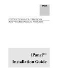
8. Outward Dimension
2MLL-EFMF
▶ RJ-45(Front view)
2MLL-EFMF’s dimension is same as 2MLL-EFMT.
` LED Discription
RUN
I/F
HS
P2P
PADT
PC
ERR
TX
RX
10/100
PHY
Discription
How to manage
Normal
ON when a fatal error occurs
Normal
ON when a fatal error occurs
On during HS Link service
Check at center
Check at center
SOFTMASTER-PD
setting check
Off
HS Link service is off
On
On P2P service
Off
P2P service is off
On
On remote service
Off
Remote service is off
On
On dedicated service use
Off
Dedicated service is off
On
Off
On
Off
On
Off
On
Off
On
Off
ON when a fatal error occurs
Normal
Blinks when sending
ON when a fatal error occurs
Blinks when receiving
ON when a fatal error occurs
100Mbps
10Mbps
Media Connected
No Connected
Unit : mm
1 2 3 4
5 6 7 8
Remark
1) Since 10/100 BASE-TX cable structure is week in external noise, the
cable of No.1 & 2 which are TD+ & TD- and No.3 & 6 which are RD+ &
SOFTMASTER-PD
setting check
RD shall be twisted respectively to be strong against noise.
2) Hub power shall be with countermeasures against noise as separat-
SOFTMASTER500
0 setting check
-ed from PLC power.
3) The cable shall be installed min. 50 mm away from high current line
MMI(HMI) setting
check
Check at center
such as power line, etc.
4) Contact an expert for terminal work, manufacture and installation of
cable.
Check at center
Check at center
98
Media check
Media check
2MLL-EFMF
HS
P2P
PADT
PC
ERR
RUN
I/F
TX
RX
PHY
Optic switch
9. Warranty
1) Warranty period
TX RX
TX RX
Honeywell 12-month-warranty for new MasterLogic PLC systems and 90-daywarranty for spare parts, from the date of delivery.
1) 2MLL-EFMT Installation
2) Warranty conditions
For troubles within the warranty period, Honeywell will replace the entire PLC or
2MLL-EFMT
HS
P2P
PADT
27
2) 2MLL-EFMF installation
6. Installation and Wiring
RUN
PC
I/F
TX
ERR
RX
10/100
90
LED
Status
On
OFF
Blink
Off, On
On
SILK
repair the troubled parts free of charge except the following cases.
Hub
(1) The troubles caused by improper condition, environment or treatment except
TX
the instructions of Honeywell.
Multi mode
RX
SC
100BASE-FX
(2) The troubles caused by external devices.
(3) The troubles caused by remodeling or repairing based on the user’s own
discretion.
(4) The troubles caused by improper usage of the product.
2MLL-EFMF
Twisted
cable
8 pin RJ-45
connector
10/100BASE-TX
2MLL-EFMT
pair
(5) The troubles caused by the reason which exceeded the expectation from
science and technology level when Honeywell manufactured the product.
100BASE-FX must use with 2 cored multimode 62.5/123 cable (SC connector)
for normal communication. It can access by optic switching hub and optic
converter. Refer to user’s manual for detailed information.
(6) The troubles caused by natural disaster.
3) This warranty is limited to the PLC itself only. It is not valid for the whole
system which the PLC is attached to.