1
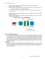
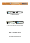
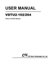
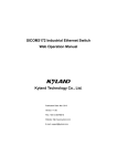
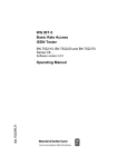
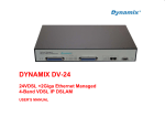
USER MANUAL VDTU-101/201 VDSL 4-band CO/CPE Modem VDSL 4-Band CO/CPE MODEM VDSL Point to Point Solution The VDTU-101/201 works as Ethernet to/from VDSL subscriber-site conversion bridge. The VDTU-101/201 uses QAM-based 4-band VDSL technologies. Which supports max distance 1.9Km (6333ft) at 5M/5M or 1.3Km (4333ft) at 15M/15M, or 800m(2666ft) at 25M/25M symmetrical data service. The VDTU-201 also works with VRM-308/VRM-324 VDSL IP DSLAM, together to form a cost-effective solution for services such as remote lecturing, telemedicine, video conferencing, Video-on-Demand (VoD), IP-TV etc. Internet access, and various high-speed data applications. The front-panel provides LED indications of system and interface status. The built-in POTS/ISDN splitter allows a standard POTS phone or ISDN device to be connected. Full or half-duplex mode of LAN operations is automatically sensed and configured. VDSL link rates are configured by local Modem or IP DSLAM over auto speed function. Therefore, VDTU-101/201 supports auto-speed, plug & play operations on the subscriber-site, and are part of an ideal solution for delivering cost-effective, high-performance broadband/multimedia services to Multi-Dwelling Units (MDU) and Multi-Tenant Units (MTU) environments such as hotels, campus, hospitals and telecom. 1 Table of Contents 1.Unpacking Information ............................................................................................. 3 Check List ................................................................................................................... 3 2. Installation............................................................................................................... 3 Hardware Installation .................................................................................................. 3 2.1 Pre-installation Requirements ..........................................................................3 General Rules ........................................................................................................4 Connecting the Modem..........................................................................................4 Connecting the RJ-11/RJ-45 ports .........................................................................4 3.Hardware Description Front Indicators………………………………………………………………….…6 Rear Connectors………………………………………………………………......7 Left Side Connector…………………………………………………………….…7 Power On…………………………………………………………………….….…7 4.Firmware Description………………………………………………………….….8 Appendix A Cable Requirement………………………………………………..…..9 Appendix B Product Features & Specifications……………………………….…10 Appendix C Trouble shooting………………………………………………….…..12 Appendix D Compliance and Safety Information…………………………….….15 FCC/CE Warning……………………………………………………………………15 Warranty……………………………………………………………………………..16 VDSL 4-band Modem Manual 1. Unpacking Information Check List Carefully unpack the package and check its contents against the checklist. Package Contents z VDSL 4-Band Modem (VDTU-101 for CO side/ VDTU-201 for CPE side) z Four plastic feet z User Manual & Utility z AC To DC Power Adapter z RJ-45 cable z RJ-11 cable z RJ-45 To D-SUB Cable(Option) Please inform your dealer immediately for any missing, or damaged parts. If possible, retain the carton, including the original packing materials, Use them to repack the unit in case there is a need to return for repair. 2. Installation Hardware Installation This chapter describes how to install the VDTU-101 & 201 MODEM and establishes network connections. You may install the VDTU1-101 & 201 MODEM on any level surface (e.g, a table or shelf). However, please take note of the following minimum site requirements before you begin. 2.1 Pre-installation Requirements Before you start actual hardware installation, make sure you can provide the right operating environment, including power requirements, sufficient physical space, and proximity to other network devices that are to be connected. Verify the following installation requirement: z Power requirements: DC5V/1A or above. z The VDTU-101 & 201 MODEM should be located in a cool dry place, with at least 10cm/4in of space at the front and back for ventilation. z Place the VDTU-101 & 201 MODEM out of direct sunlight, and away from heat sources or areas with a high amount of electromagnetic interference. z Check if network cables and connectors needed for installation are available 3 CTC Union Technologies Co., Ltd VDSL 4-band Modem Manual General Rules Before making any connections to the MODEM, note the following rules: zEthernet Port (RJ-45) All network connections to the Modem Ethernet port must be made using Category 5 UTP for 100Mbps; Category 3,4 UTP for 10Mbps No more than 100 meters of cabling may be use between the MUX or HUB and an end node. zPhone Port (RJ-11) All Phone set connections to the RJ-11 Port made using 24~26 Gauge phone wiring. Connecting the MODEM The Modem has one Ethernet port which support connection to Ethernet operation. The devices attached to these ports must support auto-negotiation or 10Base-T OR 100Base-TX unless they will always operate at half duplex. Use any of the Ethernet ports to connect to devices such as NIC, Switch, bridge or router. You can also connect to another compatible Modem to an RJ-45 port on the other device. The RJ11 Line port is used to connect to the wall RJ-11 modular socket (outlet) which is connect to VDSL 4-Band CPE Modem side (Point to point solution) The RJ11 Phone port of the Modem can connected to a telephone and a computer sharing one telephone wire for making calls and accessing the internet at the same time. Connecting the RJ-11/RJ-45 Ports 1. The Modem’s RJ-11 ports supports max distance 1.9Km at 5M/5M or max speed 25M/25M symmetrical and distances up to 800m data service across existing phone wiring, without interfering with standard voice transmissions, easy-to-use does not require the installation of any additional wiring. Every RJ-11 modular phone jack in the home can become a port on the LAN. Networking devices can be installed on a single telephone wire that can span within 1.9Km or 800m (depend on speed) between the two farthest points. (Figure 1.0). 2. VDTU-101/201 Modem has embedded Splitter between every VDSL side (Line) and POTS (Phone) side. It permit you to deliver broadband service on the same lines as Plain Old Telephone Service (POTS), PBX, ISDN traffic and VDSL Signal. 4 CTC Union Technologies Co., Ltd VDSL 4-Band CO/CPE MODEM 3.The RJ-11 port support max distance 1.9Km at 5M/5M or max speed 25M/25M symmetrical and distances up to 800m data service. When inserting a RJ-11 plug, be sure the tab on the plug clicks into position to ensure that it is properly seated. 4.Do not plug a RJ-11 phone jack connector into the Ethernet port (RJ-45 port). This may damage the modem. Instead, use only twisted-pair cables with RJ-45 connectors that conform to Ethernet standard. Notes: 1.Be sure each twisted-pair cable (RJ-45) does not exceed 100 meters (333 feet). 2.RJ-11 port use 24 ~ 26 gauge phone wiring, we do not recommend 28 gauge or above. 3.We advise using Category 3,4,5 cable for Cable Modem or Router connections to avoid any confusion or inconvenience in the future when you upgrade attached to high bandwidth devices. 4.Be sure phone cable has been installed when VDTU-101 and VDTU-201 will be power on. 5 CTC Union Technologies Co., Ltd. VDSL 4-Band CO/CPE MODEM 3. Hardware Description This section describes the important parts of the VDTU-101 & 201 MODEM. It features the front indicators and rear connectors. Front Indicators The following figure shows the front panel. Figure Chapter 2.1 VDTU-101 Modem Figure Chapter 2.2 VDTU-201 Modem At a quick glance of the front panel, it is easy to tell if the CO Modem has power, if it has signal from its Ethernet RJ-45 port and if there is phone line signal on RJ-11 port. Front Indicators LED Description and Operation The Modem has three LED indicators. LEDs Status PWR (Power LED) Steady Green It will light up (ON) to show that the product is power good, and system reset OK. Ethernet (Ethernet LED) Steady Green Flashing (LINK/ACT) Each RJ45 station port on the Ethernet is assigned an LED light for monitoring port “Good Linkage”. LED is normally OFF after the power on operation, but will light up steadily to show good linkage and flashing to show data transmission. Steady Green RJ11 station port on the VDSL is assigned an LED light for monitoring port “Good Linkage”. LED is normally OFF after the power on operation, but will light up steadily to show good linkage. LINK (VDSL LED) Descriptions 6 CTC Union Technologies Co., Ltd. VDSL 4-band Modem Manual Rear Panel The following figure shows the rear connectors Figure Chapter 2.3 Rear Connectors VDTU-101/201 &CPE MODEM Rear Connectors Description Connectors Type Line For connecting to the VDSL Modem Using a RJ-11 cable RJ-11 Phone For connecting to the telephone or Fax、ISDN Modem RJ-11 Ethernet For connecting to a Ethernet equipped device RJ-45 Left side view The following figure shows the left side connectors. You can firmware upgrade and Monitor VDSL status over console port (VDTU-101 only). Figure Chapter 2.4 Left side Connector Table Modem Rear Connectors: Connector Console port Description Type For connecting to PC with RS-232 serial port over a RJ-45 To D-SUB Cable RJ-45 Power On 1. Check the adapter is properly connected. 2. Verify the power LED is steadily on. 7 CTC Union Technologies Co., Ltd VDSL 4-band Modem Manual 4. Firmware Description Auto Speed function description. VDTU-101 is a 4band VDSL solution which supports auto speed function, they can support 5M/15M/25M symmetrical data service depend on installing environment, they will do auto speed function while phone cable be re-plug in between VDTU-101 and VDTU-201, or both be re-power on. VDTU-101 will try to link with 25M/25M mode first, if link fail will auto speed down to 15M/15M mode second, and if link fail again will auto speed down to 5M/5M, then stay on this mode until re-plug in phone cable or re-power on both. Speed mode limitation : 5M/5M mode within 1.9km (6333ft) 15M/15M mode within 1.3km (4333ft) 25M/25M mode within 800m (2666ft) Note : We recommend phone cable which must meet Cat. 3 standard or above and without clustering, otherwise the above guarantee will be void. Engineering Functions : These functions is for maintaining and troubleshooting such as firmware upgrade, command line, SNR indicator, Ethernet and VDSL port setting and status monitor and so on. And it is supporting plug and play, so end user doesn’t have to need it. 8 CTC Union Technologies Co., Ltd VDSL 4-band Modem Manual Appendix A: Cable Requirements A CAT 3,4 or 5 UTP (unshielded twisted pair) cable is typically used to connect the Ethernet device to the Modem. A 10Base-T cable often consists of four pairs of wires, two of which are used for transmission. The connector at the end of the 10Base-T cable is referred to as an RJ-45 connector and it consists of eight pins. The Ethernet standard uses pins 1,2,3 and 6 for data transmission purposes. PIN 1 2 3 4 5 6 7 8 MNEMONIC TX+ TXRX+ NC NC RXNC NC Table FUNCTION Ethernet differential Transmit signal(+) Ethernet differential Transmit signal(-) Ethernet differential receive signal(+) Unused Unused Ethernet differential receive signal(-) Unused Unused RJ-45 Ethernet Connector Pin out Assignments Standard telephone wire of any gauge or type-flat, twisted or quad is used to connect the Modem to the telephone network. A telephone cable typically consists of three pairs of wires, one of which is used for transmission. The connector at the end of the telephone cable is called an RJ-11 connector and it consists of six pins. POTS (plain old telephone services) use pins 3 and 4 for voice transmission. A telephone cable is shown below. A B Figure:Telephone cable The A and B connectors on the rear of the Modem are RJ-11 connectors. These connectors are wired identically. The RJ-11 connectors have six positions, two of which are wired .The Modem uses the center two pins. The pin out assignment for these connectors is presented below. Pin# MNEMONIC FUNCTION 1 NC Unused 2 NC Unused 3 TIP POTS 4 RING POTS 5 NC Unused 6 NC Unused Table RJ-11 Pin out Assignments 9 CTC Union Technologies Co., Ltd VDSL 4-band Modem Manual Appendix B: Product Features & Specification Product Name:VDTU-101/201 Features: ● Compliant with IEEE802.3 10BASE-T standard. ● Compliant with IEEE802.3u 100BASE-TX standard. ● Compliant with ETSI, ITU, ANSI standards ● Max distance 5M/5M distance up to 1.9km(6333ft) 15M/15M distance up to 1.3km(4333ft) Max speed 25M symmetrical and distances up to 800m(2666ft). ● Supports 1 * RJ-11 connector for Ethernet over VDSL. ● Supports 1 * RJ-11 connector for telephone/PBX connection. ● Supports 1 * RJ-45 port for 10/100Mbps Ethernet with Auto MDI/MDIX. ● Supports Auto-speed and full duplex for VDSL port. ● Supports long packet size up to 1536 bytes ● Supports POTS/ISDN voice pass. ● Supports 4wires phone set pass through. ● Supports console port for firmware upgrade and maintain (LT only). ● Voice and Data work on the same telephone line. ● Spectral compatibility with xDSL, ISDN (2B1Q/4B3T). ● Supports flow control IEEE802.3x for Full Duplex & Back Pressure for Half Duplex. ● Supports Surge protection. ● Provides Power LED. ● Provides LED indication Link/Active Status for Ethernet port and Link for VDSL port. ● External switching power adapter Input: AC 85-240 volts/50-60Hz; Output: DC 5V/1A or above. ● Mini size and metal case design 10 CTC Union Technologies Co., Ltd VDSL 4-band Modem Manual Specifications: ● Standard IEEE802.3 standard IEEE802.3u standard Compliant with ETSI, ITU, ANSI standards ● Interface ● ● ● ● ● ● ● ● ● 1 * RJ-45 10/100Mbps Ethernet port 1 * RJ-11 connector for EoVDSL 1 * RJ-11 connector for telephone connection Console port: RS-232C / 19200bps(VDTU-101 only) Cable Connections RJ-45 (Ethernet): Category 3, 4, 5 UTP/STP RJ-11 (EoVDSL): Twisted-Pair phone wire Provides LED indication Link/Active Status for Ethernet port and Link for VDSL port. VDSL Frequency Spectrum: VDTU-101_ Transmitter: 900 KHz ~ 3.9MHz Receiver: 4MHz & 7.9MHz VDTU-201_ Transmitter: 4MHz ~ 7.9MHz Receiver: 900 KHz ~ 3.9M POTS/ISDN pass filter Spectrum: 0 ~ 120K Power Consumption: VDTU-101(LT): 5.4W / VDTU-201(NT): 6W. Operating Temperature: 0°C ~ 50°C (41F ~ 122F) Storage Temperature: -20°C ~ 65°C (-4F ~ 149F) Humidity: 10 to 90% (non-condensing) Dimensions: 95 x 110 x 24 mm(3.74" x 4.33" x 0.94"). 11 CTC Union Technologies Co., Ltd VDSL 4-band Modem Manual Appendix C: Troubleshooting Diagnosing the Modem’s Indicators The Modem can be easily monitored through its comprehensive panel indicators. These indicators assist the network manager in identifying problems the hub may encounter. This section describes common problems you may encounter and possible solutions 1. Symptom: Power indicator does not light up (green) after power on. Cause: Defective External power supply Solution: Check the power plug by plugging in another that is functioning properly. Check the power cord with another device. If these measures fail to resolve the problem, have the unit power supply replaced by a qualified distributor. 2. Symptom: Link indicator does not light up (green) after making a connection. Cause: Network interface (e.g, a network adapter card on the attached device), network cable, or switch port is defective. Solution: Power off and re- power on the VDSL Modem. Verify that the switch and attached device are powered on. Be sure the cable is plugged into both the switch and corresponding device. Verify that the proper cable type is used and its length does not exceed specified limits. Check the Modem on the attached device and cable connections for possible defects. Make sure phone wire must be connected between VDTU-101 and VDTU-201 first, when both are be power on. Replace the defective Modem or cable if necessary. 3. Symptom: VDSL Link cannot be established Cause: VDSL auto speed failure, or phone cable length is over specification with the limit of 1.9km or not a 24 gauge phone wire with twist pair. Solution: 3.1 Please make sure phone wire must be connected between VDTU-101 and VDTU-201 when both are power on. VDTU-101 will do auto speed function depending on phone wire length, therefore if VDTU-101 can’t detect VDTU-201 over phone wire while both power on, this will cause the link to fail. 3.2 Please check phone cable must be 24 gauge with twist pair and without rust, and the length is not over 1.9km. Note : Phone cable must meet Cat. 3 standard or above and without clustering, otherwise will cause more cross talk issue to reduce VDSL power driver. 12 CTC Union Technologies Co., Ltd VDSL 4-band Modem Manual 4. Symptom: VDSL always Link on 5M/5M speed mode at short phone cable. Cause: VDSL auto speed stop. Solution: Please re-plug in phone cable between VDTU-101 and VDTU-201, or re-power on VDTU-101 and VDTU-201 again. Note : VDTU-101 will do auto speed function while phone cable re-plug in or re-power on. 5. Symptom: We tested with a regular S0 bus from an NTBA - data works, but ISDN telephone does not. Solution: You must connect according to the following chart if you want to connect CO and CPE with NTBA. Power and Cooling Problems If the POWER indicator does not turn on when the power cord is plugged in, you may have a problem with the power outlet, power cord, or internal power supply as explained in the previous section. However, if the unit power is off after running for a while, check for loose power connections, power losses or surges at the power outlet, and verify that the fan on back of the unit is unobstructed and running prior to shutdown. If you still cannot isolate the problem, then the internal power supply may be defective. In this case, contact your dealer. Installation Verify that all system components have been properly installed. If one or more components appear to be malfunctioning (e.g., the power cord or network cabling), test them in an alternate environment where you are sure that all the other components are functioning properly. 13 CTC Union Technologies Co., Ltd VDSL 4-band Modem Manual Transmission Mode The default method of selecting the transmission mode for RJ-45 ports is 10/100 Mbps ETHERNET, for RJ-11 port are 5/15/25Mbps VDSL. Therefore, if the Link signal is disrupted (e.g., by unplugging the network cable and plugging it back in again, or by resetting the power), the port will try to reestablish communications with the attached device via auto-negotiation. If auto-negotiation fails, then communications are set to half duplex by default. Based on this type of industry-standard connection policy, if you are using a full-duplex device that does not support auto-negotiation, communications can be easily lost (i.e., reset to the wrong mode) whenever the attached device is reset or experiences a power fluctuation. The best way to resolve this problem is to upgrade these devices to a version that support Ethernet and VDSL. Physical Configuration If problems occur after altering the network configuration, restore the original connections, and try to track the problem down by implementing the new changes, one step at a time. Ensure that cable distances and other physical aspects of the installation do not exceed recommendations System Integrity As a last resort verify the switch integrity with a power-on reset. Turn the power to the switch off and then on several times. If the problem still persists and you have completed all the preceding diagnoses, then contact your dealer 14 CTC Union Technologies Co., Ltd VDSL 4-band Modem Manual Appendix D:Compliance and Safety Information FCC Radio Frequency Interference Statement This equipment has been tested and found to comply with the limits for a computing device, pursuant to Part 15 of FCC rules. These limits are designed to provide reasonable protection against harmful interference when the equipment is operated in a commercial environment. This equipment generates, uses and can radiate radio frequency energy and, if not installed and used in accordance with the instructions, may cause harmful interference to radio communications. However, there is no guarantee that interference will not occur in a particular installation. If this equipment does cause harmful interference to radio or television reception, which can be determined by turning the equipment off and on, the user is encouraged to try to correct the interference by one or more of the following measures: 1. 2. 3. 4. Reorient or relocate the receiving antenna. Increase the separation between the equipment and receiver. The equipment and the receiver should be connected to outlets on separate circuits. Consult the dealer or an experienced radio/television technician for help. Changes or modifications not expressly approved by the party responsible for compliance could void the user’s authority to operate the equipment. If this telephone equipment causes harm to the telephone network, the telephone company will notify you in advance that temporary discontinuance of service may be required. But if advance notice isn’t practical, the telephone company will notify the customer as soon as possible. Also, you will be advised of your right to file a complaint with the FCC if you believe it is necessary. The telephone company may make changes in its facilities, equipment, operations or procedures that could affect the proper functioning of your equipment. If they do, you will be notified in advance in order for you to make necessary modifications to maintain uninterrupted service. This equipment may not be used on coin service provided by the telephone company. Connection to party lines is subject to state tariffs. 15 CTC Union Technologies Co., Ltd VDSL 4-Band CO/CPE MODEM Important Safety Instructions Caution:The direct plug-in wall transformer serves as the main disconnect for the product. The socket outlet shall be installed near the product and be readily accessible. Caution:Use only the power supply included with this product. In the event the power supply is lost or damaged:In the United States, use only with CSA certified or UL listed Class 2 power supply, rated 5Vdc 1A or above. IN Europe, use only with CE certified power supply, rated 5Vdc 1A or above. Do not use this equipment near water, for example in a wet basement. Avoid using a telephone during an electrical storm. There may be a remote risk of electrical shock from lightning. Do not use the telephone to report a gas leak in the vicinity of the leak. If trouble is experienced with this unit, please contact customer service at the address and phone listed below. Do not disassemble this equipment. It does not contain any user serviceable components. FCC Warning This equipment has been tested and found to comply with the limits for a Class A digital device, pursuant to Part 15 of the FCC Rules. These limits are designed to provide reasonable protection against harmful interference when the equipment is operated in a commercial environment. This equipment generates, uses, and can radiate radio frequency energy and, if not installed and used in accordance with the instruction manual, may cause harmful interference to radio communications. Operation of this equipment in a residential area is likely to cause harmful interference in which case the user will be required to correct the interference at his own expense. CE Mark Warning This is a CE class A product. In a domestic environment, this product may cause radio interference in which case the user may be required to take adequate measures. 16 CTC Union Technologies Co., Ltd. VDSL 4-band Modem Manual Warranty The original owner that the product delivered in this package will be free from defects in material and workmanship for one year parts after purchase. There will be a minimal charge to replace consumable components, such as fuses, power transformers, and mechanical cooling devices. The warranty will not apply to any products which have been subjected to any misuse, neglect or accidental damage, or which contain defects which are in any way attributable to improper installation or to alteration or repairs made or performed by any person not under control of the original owner. The above warranty is in lieu of any other warranty, whether express, implied, or statutory, including but not limited to any warranty of merchantability, fitness for a particular purpose, or any warranty arising out of any proposal, specification, or sample. Shall not be liable for incidental or consequential damages. We neither assumes nor authorizes any person to assume for it any other liability. Note: Please do not tear off or remove the warranty sticker as shown, otherwise the warranty will be void. 17 CTC Union Technologies Co., Ltd