1
GL-241101
Wireless LAN PCMCIA Card
USER MANUAL
Version 1.0, Dec. 20, 2000
Federal Communications Commission Statement
This device complies with FCC Rules Part 15. Operation is subject to the following two conditions:
This device may not cause harmful interference.
This device must accept any interference received, including interference that may cause undesired
operation.
This equipment has been tested and found to comply with the limits for a Class B digital device,
pursuant to Part 15 of the FCC Rules. These limits are designed to provide reasonable protection
against harmful interference in a residential installation. This equipment generates, uses and can
radiate radio frequency energy. If this equipment is not installed and used in accordance with the
manufacturer's instructions, it may cause harmful interference to radio communications. However,
there is no guarantee that interference will not occur in a particular installation. If this equipment
does cause harmful interference to radio or television reception, which can be determined by during
the equipment off and on, the user is encouraged to try to correct the interference by one or more
of the following measures:
Reorient or relocate the receiving antenna.
Increase the separation between the equipment and receiver.
Connect the equipment to an outlet on a circuit different from that to which the receiver is
connected.
Consult the dealer or an experienced radio/TV technician for help.
The use of shielded cables for connection of the monitor to the graphics card is required to assure
compliance with FCC regulations. Changes or modifications to this unit not expressly approved by
the party responsible for compliance could void the user's authority to operate this equipment.
Manufacturer's Disclaimer Statement
The information in this document is subject to change without notice and does not represent a
commitment on the part of the vendor. No warranty or representation, either expressed or implied,
is made with respect to the quality, accuracy or fitness for any particular purpose of this document.
The manufacturer reserves the right to make changes to the content of this document and/or the
products associated with it at any time without obligation to notify any person or organization of
such changes. In no event will the manufacturer be liable for direct, indirect, special, incidental or
consequential damages arising out of the use or inability to use this product or documentation,
even if advised of the possibility of such damages. This document contains materials protected by
copyright. All rights are reserved. No part of this manual may be reproduced or transmitted in any
form, by any means or for any purpose without expressed written consent of its authors. Product
names appearing in this document are mentioned for identification purchases only. All trademarks,
product names or brand names appearing in this document are registered property of their
respective owners.
Printed in Taiwan
2
Contents
Chapter 1 About the GL-241101 PCMCIA Card ........................................................ 4
1-1 Features............................................................................................................................................... 4
1-2 Applications ......................................................................................................................................... 4
1-3 Product Kit ........................................................................................................................................... 5
Chapter 2 Network Configuration and Planning ...................................................... 6
2-1 Network Topology................................................................................................................................ 6
2-2 Roaming .............................................................................................................................................. 8
Chapter 3 Adapter Installation and Configuration ................................................... 9
3-1 System Requirements ......................................................................................................................... 9
3-2 Inserting the GL-241101 PC CARD..................................................................................................... 9
3-3 GL-241101 Driver Installation -Windows® 95 .................................................................................... 10
3-4 GL-241101 Driver Installation -Windows® 98 .................................................................................... 19
3-5 GL-241101 Driver Installation -Windows® 2000 ................................................................................ 29
3-6 GL-241101 Driver Installation -Windows® Me ................................................................................... 37
3-7 GL-241101 Setup for Windows® NT 4.0 ............................................................................................ 46
3-8 GL-241101 Setup for Linux................................................................................................................ 50
Chapter 4 Installing & Navigating the Configuration Utility .................................. 55
4-1 PRISM Configuration Utility - Installation........................................................................................... 55
4-2 Configuration Utility- Navigation ........................................................................................................ 57
Appendix A Troubleshooting................................................................................... 62
Appendix B Glossary................................................................................................ 64
3
Chapter 1 About the GL-241101 PCMCIA Card
The GL-241101 IEEE 802.11b PCMCIA PC Card is compatible with any standard, notebook
computer Type II or Type III PCMCIA slot. As a Plug-and-Play device, Windows 95/98 will
automatically recognize the GL-241101 PCMCIA card and initiate the installation process. Upon
successful installation, the GL-241101 PCMCIA card will communicate seamlessly with other GL241101 wireless home and office networking products.
1-1 FEATURES
1.
Supports up to 11 Mbps data rate: T-1 line alternative/replacement that dramatically cuts
costs.
2.
Working range up to 800 ft. in an open environment enhances mobility.
3.
Supports point-to-point and point-to-multipoint access provides increased flexibility.
4.
Seamless connectivity to wired Ethernet and PC network LAN’s offers quick, trouble-free
integration with existing networks.
5.
Robust Direct Sequence Spread Spectrum (DSSS) technology provides secure,
interference-resistant wireless connection.
6.
Wireless connections eliminate the hassle and cost of cabling.
7.
Supports a wide range of LAN (Local Area Network) Network Operating Systems (NOS)
including Windows ® 98 and Windows NT™
8.
Easy Plug and Play installation
9.
Omni - directional antenna included
10. Greater flexibility to locate or move networked PC’s
1-2 APPLICATIONS
GL-241101 products offer a fast, reliable, cost-effective solution for wireless client access to the
network the following applications and environments:
Remote access to corporate network information
E-mail, file transfer and terminal emulation
Difficult-to-wire environments
Historic or older buildings
Buildings with asbestos insulation
Open areas where wiring is difficult to employ
Frequently changing environments
Retailers, manufacturers or other organizations that frequently rearrange the workplace or
relocate
Temporary LANs for special projects or peak time usage
4
Trade shows, exhibitions and construction sites that employ temporary networks.
Retailers, airline and shipping companies that need additional workstations for a peak
period and Auditors that require workgroups at customer sites.
Access to database for mobile workers
Medical, Technical and Retail specialists that require roaming access to a database or
other network resources.
SOHO (Small Office and Home Office) users
Perfect for users that need a small, easy-to-install network that deploys rapidly.
Inter-building connection
Wireless building-to-building networks are quickly and easily installed, require no monthly
lease fees, and provide the flexibility to reconfigure easily.
1-3 PRODUCT KIT
The GL-241101 product kit includes the following items. Ensure that the items in the following list
have been included. If any of the listed items are missing, please contact your local dealer.
1 X GL-241101 PCMCIA Type II Adapter
1 X Driver
1 X User Manual & Utility CD pack
5
Chapter 2 Network Configuration and Planning
The GL-241101 supports legacy Ethernet LAN network configuration options as defined by the
IEEE 802 standards committee.
The GL-241101 can be configured as:
Ad-Hoc for departmental or SOHO LANs
Infrastructure for enterprise LANs
LAN-Interconnection for point-to-point link as a campus backbone
2-1 NETWORK TOPOLOGY
Notebook
with
GL-241101
Desktop PC
with
GL-241101
Ad Hoc
Wireless LAN
Notebook
with
GL-241101
Desktop PC
with
GL-241101
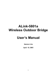
Fig. 1 - Ad-Hoc Wireless LAN
An Ad-Hoc wireless LAN is a group of computers, each equipped with one GL-241101 PC Card,
connected as an independent wireless LAN. Computers in a specific Ad-Hoc wireless LAN must be
configured to share the same radio channel.
Ad-Hoc wireless LAN configurations are appropriate for branch level departments or SOHO
operations
6
Desktop PC with ethernet
Desktop PC with ethernet
Sever
Ethernet
Notebook
with
GL-241101
Notebook
with
GL-241101
GL-2411AP
GL-2411AP
Notebook
with
GL-241101
Desktop PC
with
GL-241101
Desktop PC
with
GL-241101
Desktop PC
with
GL-241101
Infrastructure
Wireless LAN
Infrastructure
Wireless LAN
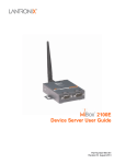
Fig. 2 - Infrastructure Wireless LAN Configuration
The GL-241101 provides access to a wired LAN for wireless workstations. An integrated wireless
and wired LAN is called an Infrastructure configuration. A group of GL-241101 PC users and an
Access Point compose a Basic Service Set (BSS). Each GL-241101 PC in a BSS can talk to any
computer in the wired LAN infrastructure via the Access Point.
An Infrastructure configuration extends the accessibility of a GL-241101 equipped PC to a wired
LAN, and doubles the effective wireless transmission range for 2 GL-241101 PCs. Since the
Access Point is able to forward data within its BSS, the effective transmission range in an
infrastructure LAN is doubled.
Ad Hoc
Notebook
with
GL-241101
Notebook
with
GL-241101
Notebook
with
GL-241101
GL-2411AP
Infrastructure
Notebook
with
GL-241101
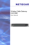
Fig. 3 - The effective Transmission Range
The use of a unique ID in a BSS is essential. All GL-241101 equipped PCs configured without
roaming options in an independent BSS must be configured with a BSS ID corresponding to the
GL-2411AP used in the BSS. Check your GL-2411AP for its BSS ID or use the Access Point
Browser Utility program to determine the BSS ID.
The Infrastructure Wireless LAN configuration is appropriate for enterprise-scale wireless access to
a central database, or as a wireless application for mobile users.
7
A point-to-point LAN configuration is possible when two access points are linked with an optional
directional antenna (the directional antenna is an optional accessory, please contact your dealer for
information). The optional directional antenna makes LAN-Interconnection to a wireless backbone
between buildings possible.
2-2 ROAMING
Infrastructure mode also supports roaming capabilities for mobile users. More than one BSS can be
configured as an Extended Service Set (ESS). The continuous network allows users to roam freely
within an ESS. All GL-241101 PCs and GL-2411APs within one ESS must be configured with the
same ESS ID and use the same radio channel.
Desktop PC with ethernet
Desktop PC with ethernet
Sever
Ethernet
Notebook
with
GL-241101
Notebook
with
GL-241101
GL-2411AP
Roaming
BSS1
Notebook GL-2411AP
with
GL-241101
Notebook
with
GL-241101
BSS2
Desktop PC
with
GL-241101
ESS
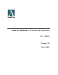
Fig. 4 - Roaming in an Extended Service Set (ESS)
Before enabling an ESS with roaming capability, choosing a feasible radio channel and optimum
Access Point position is recommended. Proper Access Point positioning combined with a clear
radio signal will greatly enhance performance.
8
Chapter 3 Adapter Installation and Configuration
3-1 SYSTEM REQUIREMENTS
In order to install and use the GL-241101 PCMCIA card your PC system must meet the following
requirements:
A PCMCIA Type II or Type III slot
PCMCIA revision 2.10 compliant card and socket services
Windows® 95,98,ME.2000 or NT (with the Windows® CD, for use during installation)
500 Kbytes free disk space for utility and driver installation
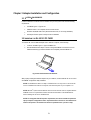
3-2 INSERTING THE GL-241101 PC CARD
To insert the GL-241101 Network Adapter into a notebook computer, do the following:
1.
Locate an available Type II or Type III PCMCIA slot.
2.
With the PCMCIA Card’s 68-pin connector facing the PCMCIA slot and the GL-241101
PCMCIA label facing up slide the PCMCIA Card completely into the PCMCIA slot.
Fig. 5 Insert the GL-241101 into Notebook
After properly inserting the Network Adapter into your notebook, continue with the GL-241101 driver
and PRISM Configuration Utility installation.
NOTE: The PCMCIA slot allows “hot swap” of PCMCIA Card. You may insert or remove the GL241101 / PCMCIA Card from the slot anytime, even when the power of your computer is on.
NOTE: Windows® requires that the Network card and socket services must be compliant with the
PCMCIA revision 2.10 specification. Please check the documentation of the PCMCIA driver
before installing the GL-241101 PCMCIA Card.
NOTE: To comply with FCC RF exposure requirements, this device should be operated in
lap-top computer configurations with a separation distance of 20 cm or more between the
antenna and persons. The antenna should not be operated next to a person’s body.
9
3-3 GL-241101 DRIVER INSTALLATION -WINDOWS® 95
Note: Before proceeding, have the Windows® 95 CD ready, as it will be required during the
software installation process.
1.
Insert the GL-241101 Card into a standard Type II or Type III PCMCIA card slot, as
described in the preceding section.
2.
Windows® 95 will automatically detect the GL-241101 and prompt you to install the
necessary driver. Click “Next” to begin the installation.
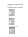
3.
Check “Other Locations…“ and click “Next”.
4.
Check “CD-ROM Driver” click “Browse”. Double-click the “d:\pc-oem\driver\Win9x” folder
icon from the list. Windows® will automatically enter the path click “Next”. (where “D”
represents the CD-ROM drive)
5.
Windows® will then acknowledge that it has found the appropriate driver, click “Next”
10
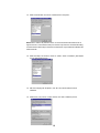
6.
As the driver files are being copied to the appropriate location, Windows® 95 may want
you to relocate the driver. Then you browse the “D:\pc-oem\driver\\win9x” location and
click “OK” to continue. (where “D” represents the CD-ROM drive)
7.
Windows® will now install the driver. As the driver files are being copied to the appropriate
location, you will be prompted to insert the Windows® 95 CD. Insert the Windows® 95 CD.
Select “C:\win95” from the drop down list (where “C” represents the Windows® 95 set up
source), click “OK”
8.
You will be prompted to restart your computer and click "Yes" to complete the installation.
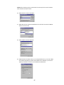
9.
After successful installation of the GL-241101 and its driver, continue the installation
process by configuring the GL-241101 PC Card properties. From the Control Panel,
double-click the “Network” icon.
11
10. Select "PRISM2 IEEE 802.11 PC Card Adapter" from the list and press the “Properties”
button.
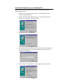
11. From the “Properties” menu, please select the “Advanced” tab.
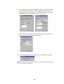
12. Select “Adhoc STA – ATIM Windows” and set up the default value 0 from a range
between 0 and 100 (See Appendix B Glossary).
12
13. Select “Authentication Algorithm” and set up the default value: WECA Compliant (See
Appendix B Glossary).
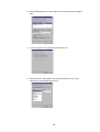
14. Select “Channel” from the list, and choose a “Value” from the drop down list. FCC
regulations require a “Value” between 1 and 11 and ETSI between 1 and 13.
15. Select “Fragmentation Threshold” and set up the default value: 2432 (See Appendix B
Glossary).
13
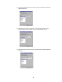
16. Select “Infrastructure STA – Listen Interval” and set up default value: 3 (See Appendix B
Glossary).
17. Select “Network Type”, and choose “Infrastructure”, “Ad-Hoc” or “802.11b Ad-Hoc” as the
“Value”.
NOTE: “Infrastructure” mode allows a wireless adapter to communicate with a wired network,
while “Ad-Hoc” and “802.11b Ad-Hoc” mode allow wireless-to-wireless communication.
Consult your System Administrator for information about your network communication type.
For more information about Infrastructure and Ad-Hoc networks, see Chapter 2 of this manual
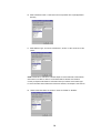
18. Select “Power Save Mode” and choose a “Value” for “Enabled” or “Disabled”.
14
NOTE: To allow uninterrupted data communication, choose “Disabled” as the ”Value”.
Choosing “Enabled” allows your notebook to enter “sleep” mode, however, this will interrupt
data communication. Consult your System Administrator to find out the best setting for your
network type. For more information about Power Save Mode, see the chapter entitled “PRISM
Configuration Utility” in this manual.
19. Select “Preamble Mode” and set up the default value: Long Tx Preamble (See Appendix
B Glossary).
20. Select “RTS Threshold” and set up default value: 2432 (See Appendix B Glossary).
21. The SSID can have any value, but should have the same value as the Access Point (AP).
In Ad-Hoc mode, all clients should share the same SSID.
15
22. Select “Transmit Rate”, and choose a default value as “Fully Auto”.
NOTE: Fixed 11 Mb/s is the preferred “Value” for environments where the client has line of
sight access and is a short distance away from the AP. Fully Auto is the recommended setting
for clients that are farther away from the AP and where there may be interference between the
client and the AP.
23. Select “Use Wep”, and choose a “Value” for “128 bit”, “64 bit” or “Disabled”. (See Chapter
4-2 and Appendix B Glossary).
24. After the configuring the “Properties”, click “OK” and continue with the Protocol
Installation.
25. Please check your protocol. If it lacks TCP/IP, click “Add” to install the protocol.
16
NOTE: Before installing any protocol, please make sure that the protocol has been installed.
Never install the same protocol twice.
26. Select “Protocol” and click “Add” button.
27. Select “Microsoft” from the list of “Manufacturers” and “TCP-IP” from the list of “Network
Protocols”, then click “OK”
28. Select “TCP/IP “ and click “Properties”.
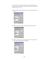
29. Please select the “IP Address” tab. If you are using a DHCP server, you can click “Obtain
an IP address automatically” to get IP from the DHCP sever. Otherwise, you must click
“Specify an IP address” and key in your IP address and subnet mask.
17
30. If you use DHCP sever, please click “OK” and jump to step 31. If you do not use a DHCP
server and must manually enter the IP address and DNS number. Please select the
“Gateway” tab and key in your gateway. Then select the “DNS Configuration” tab and key
in the DNS sever IP address which is near your PC. Then click “OK”.
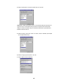
31. From the “Network” menu, please select the “Advanced” tab. Enter a “Computer name”,
“Workgroup” and “Computer Description”, then click “OK”.
32. You will be prompted to restart your computer, click “Yes” to complete the installation.
NOTE: Please see the trouble shooting if you encounter some problem while installing the PCCard or your PC-Card is non-functional.
18
3-4 GL-241101 DRIVER INSTALLATION -WINDOWS® 98
Note: Before proceeding, have the Windows® 98 CD ready, as it will be required during the
software installation process.
1.
Insert the GL-241101 Card into a standard Type II or Type III PCMCIA card slot, as
described in the preceding section.
2.
Windows® 98 will automatically detect the GL-241101 and prompt you to install the
necessary driver. Click “Next” to begin the installation.
3.
Check “Search for the best driver… “ and click “Next”.
4.
Check “CD-ROM Driver” and click “Browse”. Double-click the “D:\PC-OEM\Driver\Win9x”
folder icon from the list. Windows® will automatically enter the path click “Next”. (where
"D" represents a CD-ROM)
19
5.
Windows® will then acknowledge that it has found the appropriate driver, click “Next”
Windows® will now install the driver
As the driver files are being copied to the appropriate location, you will be prompted to
insert the Windows® 98 CD.
6.
Insert the Windows® 98 CD. Select “D:\win98” from the drop down list (where “D”
represents the CD-ROM drive), click “OK”.
NOTE: You must insert the Windows 98®CD as the driver installation requires special files that
will not be available even if you have stored a copy of Windows® 98 on your hard drive.
7.
After Windows® has finished installing the appropriate files click “Finish”
20
8.
You will be prompted to restart your computer and click "Yes" to complete the installation.
9.
After successful installation of the GL-241101 and its driver, continue the installation
process by configuring the GL-241101 PC Card properties. From the Control Panel,
double-click the “Network” icon.
10. Select "PRISM2 IEEE 802.11 PC Card Adapter" from the list and press the “Properties”
button.
11. From the “Properties” menu, please select the “Advanced” tab.
21
12. Select “Adhoc STA – ATIM Windows” and set up a default value 0 from a range between
0 and 100 (See Appendix B Glossary).
13. Select “Authentication Algorithm” and set up a default value: WECA Compliant (See
Appendix B Glossary).
14. Select “Channel” from the list, and choose a “Value” from the drop down list. FCC
regulations require a “Value” between 1 and 11 and ETSI between 1 and 13.
22
15. Select “Fragmentation Threshold” and set up a default value: 2432 (See Appendix B
Glossary).
16. Select “Infrastructure ATS – Listen Interval” and set up a default value: 3 (See Appendix
B Glossary)
17. Select “Network Type”, and choose “Infrastructure”, “Ad-Hoc” or “802.11b Ad-Hoc” as the
“Value”.
NOTE: “Infrastructure” mode allows a wireless adapter to communicate with a wired network,
while “Ad-Hoc” and “802.11b Ad-Hoc” mode allow wireless-to-wireless communication.
Consult your System Administrator for information about your network communication type.
For more information about Infrastructure and Ad-Hoc networks, see Chapter 2 of this manual
23
18. Select “Power Save Mode” and choose a “Value” for “Enabled” or “Disabled”.
NOTE: To allow uninterrupted data communication, choose “Disabled” as the ”Value”.
Choosing “Enabled” allows your notebook to enter “sleep” mode, however, this will interrupt
data communication. Consult your System Administrator to find out the best setting for your
network type. For more information about Power Save Mode, see the chapter entitled “PRISM
Configuration Utility” in this manual.
19. Select “Preamble Mode” and set up a default value: Long Tx Preamble (See Appendix B
Glossary).
20. Select “RTS Threshold” and set up a default value: 2432 (See Appendix B Glossary).
24
21. The SSID can have any value, but should have the same value as the Access Point (AP).
In Ad-Hoc mode, all clients should share the same SSID.
22. Select “Transmit Rate”, and choose a default value as “Fully Auto”.
NOTE: Fixed 11 Mb/s is the preferred “Value” for environments where the client has line of
sight access and is a short distance away from the AP. Fully Auto is the recommended setting
for clients that are farther away from the AP and where there may be interference between the
client and the AP.
23. Select “Use Wep”, and choose a “Value” for “128 bit”, “64 bit” or “Disabled”. (See Chapter
4-2 and Appendix B Glossary).
25
24. After the configuring the “Properties”, click “OK” and continue with the Protocol
Installation.
25. Please check your protocol. If it lacks TCP/IP, click “Add” to install the protocol.
NOTE: Before installing any protocol, please make sure that the protocol has been installed.
Never install the same protocol twice.
26. Select “Protocol” and click “Add” button.
27. Select “Microsoft” from the list of “Manufacturers” and “TCP-IP” from the list of “Network
Protocols”, then click “OK”
28. Select “TCP/IP “ and click “Properties”.
26
29. Please select the “IP Address” tab. If you are using a DHCP server, you can click “Obtain
an IP address automatically” to get IP from the DHCP sever. Otherwise, you must click
“Specify an IP address” and key in your IP address and subnet mask.
30. If you use DHCP sever, please click “OK” and jump to step 31. If you do not use a DHCP
server and must manually enter the IP address and DNS number. Please select the
“Gateway” tab and key in your gateway. Then select the “DNS Configuration” tab and key
in the DNS sever IP address which is near your PC. Then click “OK”.
31. From the “Network” menu, please select the “Advanced” tab. Enter a “Computer name”,
“Workgroup” and “Computer Description”, then click “OK”.
27
32. You will be prompted to restart your computer, click “Yes” to complete the installation.
Note: Please see the trouble shooting if you encounter some problem while installing the PCCard or your PC-Card is non-functional.
28
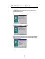
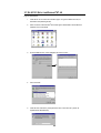
3-5 GL-241101 DRIVER INSTALLATION -WINDOWS® 2000
1.
Insert the GL-241101 PC Card into a standard Type II or Type III PCMCIA card slot, as
described in the preceding section. Then insert the driver CD into the CD-ROM.
2.
Windows® 2000 will automatically detect the GL-241101 and prompt you to install the
necessary driver. Click “Next” to begin the installation.
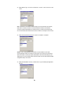
3.
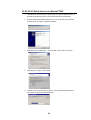
Select “Search for a suitable driver…” and click “Next” to find the GL-241101 driver.
4.
Select “Specify a location” and click “Next”.
5.
Insert the driver disk into the floppy. Then key in “d:\pc-oem\driver\win2000” and click
“OK”. (where “D” represents the CD-ROM drive)
29
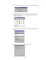
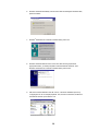
6.
Windows® 2000 will automatically scan the driver. After acknowledge of Windows® 2000,
please click "Next".
7.
Windows® 2000 will show a windows information dialog. Click “Yes”.
8.
Windows® 2000 will install the driver. As the driver files are being copied to the
appropriate location, you will be prompted to insert the Windows® 2000 CD. Then
Windows® 2000 will show a windows information dialog. Click “Finish”.
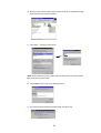
9.
After the successful installation of the GL-241101, continue the installation process by
configuring the GL-241101 adapter properties. First, from the Control Panel, double-click
the “Network and Dial-up Connections” icon.
30
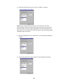
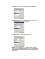
10. Move the mouse to the local area connection which the GL-241101 generates and rightclick the mouse. Then click the “Properties”.
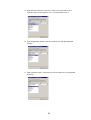
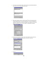
11. Click “Install…” and “Add” to add protocols.
NOTE: Before installing any protocol, please make sure that the protocol has been installed.
Never install the same protocol twice.
12. Click “NetBEUI Protocol” and “OK” to install the protocol.
13. The system will show a windows information dialog. Click “No” to skip.
31
14. Repeat step 11. Then click “NWLink IPX/SPX/NetBIOS Compatible Protocol” and “OK” to
install the protocol.
15. The system will also show the windows information dialog above. Click “No” to skip.
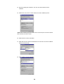
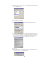
16. Click “Configure” to configure the adapter.
17. From the menu, please select “Advanced” tab and it will show the “Property” and “Value”.
First, Select “ Adhoc ATS - ATIM Windows” and set up a default value: 0 from a range
between 0 and 100 (See Appendix B Glossary).
18. Select “Authentication Algorithm” and set up a default value: WECA Compliant (See
Appendix B Glossary).
32
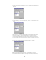
19. Select “Channel” from the list, and choose a “Value” from the drop down list. FCC
regulations require a “Value” between 1 and 11 and ETSI between 1 and 13.
20. Select “Fragmentation Threshold” and set up a default value: 2432 (See Appendix B
Glossary ).
21. Select “Infrastructure ATS – Listen Interval” and set up a default value: 3 (See Appendix
B Glossary).
33
22. Select “Network Type”, and choose “Infrastructure”, “Ad-Hoc” or “802.11b Ad-Hoc” as the
“Value”.
Note: “Infrastructure” mode allows a wireless adapter to communicate with a wired network,
while “Ad-Hoc” and “802.11b Ad-Hoc” mode allow wireless-to-wireless communication.
Consult your System Administrator for information about your network communication type.
For more information about Infrastructure and Ad-Hoc networks, see Chapter 2 of this manual
23. Select “Power Save Mode” and choose a “Value” for “Enabled” or “Disabled”.
NOTE: To allow uninterrupted data communication, choose “Disabled” as the ”Value”.
Choosing “Enabled” allows your notebook to enter “sleep” mode, however, this will interrupt
data communication. Consult your System Administrator to find out the best setting for your
network type. For more information about Power Save Mode, see the chapter entitled “PRISM
Configuration Utility” in this manual.
24. Select “Preamble Mode” and set up a default value: Long Tx Preamble (See Appendix B
Glossary).
34
25. Select “RTS Threshold” and set up a default value: 2432 ( See Appendix B Glossary )
26. The SSID can have any value, but should have the same value as the Access Point (AP).
In Ad-Hoc mode, all clients should share the same SSID.
27. Select “Transmit Rate”, and choose a default value as “Fully Auto”.
NOTE: Fixed 11 Mb/s is the preferred “Value” for environments where the client has line of
sight access and is a short distance away from the AP. Fully Auto is the recommended setting
for clients that are farther away from the AP and where there may be interference between the
client and the AP.
35
28. Select “Use Wep”, and choose a “Value” for “128 bit”, “64 bit” or “Disabled”. (See Chapter
4-2 and Appendix B Glossary).
29. After configuration, please click “OK”.
30. Click “Internet Protocol (TCP/IP)” and “Properties” to initialize the TCP/IP Protocol.
31. If you are using a DHCP server, you can click “Obtain an IP address automatically” to get
IP from the DHCP sever. Otherwise, you must click “Use the following IP address” and
key in your IP address, subnet mask and default gateway. Then you may also key in the
DNS sever IP address which is near your PC. After keying in all IPs, click “OK”
32. Click “Close”.
33. Windows® 2000 will show a windows information dialog. You will be prompted to restart
your computer. Click “Yes” to complete the installation.
36
3-6 GL-241101 DRIVER INSTALLATION -WINDOWS® ME
NOTE: Before proceeding, have the Windows® Me CD ready, as it will be required during the
software installation process.
1. After inserting the GL-241101 PCMCIA card into a standard type II or type III PCMCIA card
slot and powering on the PC under Windows® Me, Windows® Me will automatically detect
the GL-241101 and prompt you to install the necessary driver. Check “Specify the location
of the driver (Advanced)” and click “Next” to begin the installation.
2. Insert the driver disk. Check “Specify a location” and browse “D:\pc-oem\driver\WIN9x”
folder. Then click “Next”. (where “D” represents the CD-ROM drive)
3. Windows® Me will automatically scan the driver. After acknowledge of Windows® Me, please
click "Next".
4. Windows® Me will install the driver. As the driver files are being copied to the appropriate
location, you will be prompted to insert the Windows® ME CD.
5. After installation, please click "Yes" to reboot the PC.
37
6. After successful installation of the GL-241101 and its driver, continue the installation
process by configuring the GL-241101 adapter properties. To configure the GL-24110P
Adapter completes the following steps.
7. From the desktop, move the mouse to “My Network Places”. Click-right the button and
select “Properties”
8. Click “Add” to add complete protocols.
NOTE: Before installing any protocol, please make sure that the protocol has been installed.
Never install the same protocol twice.
9. Select “Protocol” and click “Add”.
10. Select “Microsoft” from the list of “Manufacturers” and “IPX/SPX-compatible Protocol” from
the list of “Network Protocols”. Then click “OK”.
38
11. Repeat step 8 to 10. Select “Microsoft” from the list of “Manufacturers” and “NetBEUI” from
the list of “Network Protocols”. Then click “OK”.
12. Select "PRISM2 IEEE 802.11 PC Card Adapter" from the list and press the “Properties”
button.
13. From the “Properties” menu, please select the “Advanced” tab.
14. Select “Adhoc ATS – ATIM Window” and set up a default value 0 from a range between 0
and 100 (See Appendix B Glossary).
39
15. Select “Authentication Algorithm” and set up a default value: WECA Compliant (See
Appendix B Glossary).
16. Select “Channel” from the list, and choose a “Value” from the drop down list. FCC
regulations require a “Value” between 1 and 11 and ETSI between 1 and 13.
17. Select “Fragmentation Threshold” and set up a default value: 2432 (See Appendix B
Glossary).
40
18. Select “Infrastructure ATS – Listen Interval” and set up a default value: 3 (See Appendix B
Glossary).
19. Select “Network Type”, and choose “Infrastructure” , “Ad-Hoc” or “802.11b Ad-Hoc” as the
“Value”.
Note: “Infrastructure” mode allows a wireless adapter to communicate with a wired network,
while “Ad-Hoc” and “802.11b Ad-Hoc” mode allow wireless-to-wireless communication.
Consult your System Administrator for information about your network communication type.
For more information about Infrastructure and Ad-Hoc networks, see Chapter 2 of this manual
20. Select “Power Save Mode” and choose a “Value” for “Enabled” or “Disabled”.
NOTE: To allow uninterrupted data communication, choose “Disabled” as the ”Value”.
Choosing “Enabled” allows your notebook to enter “sleep” mode, however, this will interrupt
41
data communication. Consult your System Administrator to find out the best setting for your
network type. For more information about Power Save Mode, see the chapter entitled “PRISM
Configuration Utility” in this manual.
21. Select “Preamble Mode” and set up a default value: Long Tx Preamble (See Appendix B
Glossary).
22. Select “RTS Threshold” and set up a default value: 2432 (See Appendix B Glossary).
23. The SSID can have any value, but should have the same value as the Access Point (AP).
In Ad-Hoc mode, all clients should share the same SSID.
42
24. Select “Transmit Rate”, and choose a default value as “Fully Auto”.
NOTE: Fixed 11 Mb/s is the preferred “Value” for environments where the client has line of
sight access and is a short distance away from the AP. Fully Auto is the recommended
setting for clients that are farther away from the AP and where there may be interference
between the client and the AP.
25. Select “Use Wep”, and choose a “Value” for “128 bit”, “64 bit” or “Disabled”. (See Chapter
4-2 and Appendix B Glossary).
26. After the configuring the “Properties”, click “OK”.
27. Select “TCP/IP” and click “Properties”.
43
28. From the “TCP/IP Properties” menu, please select the “IP Address” tab. If you are using a
DHCP server, you can click “Obtain an IP address automatically” to get IP from the DHCP
sever. Otherwise, you must click “Specify an IP address” and key in your IP address and
subnet mask.
29. If you use DHCP sever, please click “OK” and jump to step 32. If you do not use a DHCP
server and must manually enter the IP address and DNS number. Please select the
“Gateway” tab and key in your gateway. Then select the “DNS Configuration” tab and key
in the DNS sever IP address which is near your PC. Then click “OK”.
30. From the “Network” menu, please select the “Identification” tab. Enter a “Computer name”
“Workgroup” and “Computer Description”. Click “OK”.
44
31. You will be prompted to restart your computer. Click “Yes” to complete the installation.
45
3-7 GL-241101 SETUP FOR WINDOWS® NT 4.0
Login as Administrator
1.
Insert the GL-241101 Card into a standard Type II or Type III PCMCIA card slot, as
described in the preceding section.
2.
Power on the PC under Windows® NT4.0 and login as Administrator and double-click
“Network” from Control Panel.
3.
From the Network menu, select “Adapters” tab and click “Add…”.
4.
Click “Have Disk”
5.
Insert the driver CD and key in the path of the driver. Then click “OK”. (where “D”
represents the CD-ROM drive)
46
6.
Select “PRISM2 IEEE 802.11 PC Card Adapter” and click “OK”.
7.
Windows® NT4.0 will show a configuration dialog and you may click “OK”.
NOTE:
A. You many change the I/O Base and IRQ Level which setting should be unique and
avoid any possible conflicts with other system devices.
B. Mode : “Infrastructure” mode allows a wireless adapter to communicate with a wired
network by connecting with an Access Point, while “Ad-Hoc” and “802.11b Ad-Hoc”
mode allows wireless-to-wireless communication. Consult your System Administrator
for information about your network communication type. For more information about
Infrastructure and Ad-Hoc networks, see Chapter 2 of this manual.
C. SSID : The SSID can have any value, but should have the same value as the Access
Point (AP) in the “Infrastructure Mode”. In Ad-Hoc mode, all clients should share the
same SSID for communication.
D. DS Channel : Select “Channel” from the list and choose a “Value” from the drop down
list. FCC regulations require a “Value” between 1 and 11 and ETSI between 1 and 13.
E : Tx Rate : Fixed 11 Mb/s is the preferred “Value” for environments where the client
has line of sight access and is a short distance away from the AP. Fully Auto is the
recommended setting for clients that are farther away from the AP and where there may
be interference between the client and the AP.
F : RTS Threshold, Fragmentation Threshold, WEP, ATIM Windows and Listen Interval:
See Appendix B Glossary
G . Power Saving : To allow uninterrupted data communication, choose “Disabled” as
the ”Value”. Choosing “Enabled” allows your notebook to enter “sleep” mode, however,
this will interrupt data communication. Consult your System Administrator to find out the
best setting for your network type. For more information about Power Save Mode, see
the chapter entitled “PRISM Configuration Utility” in this manual.
47
8.
Click “Close” from the “Network” dialog, Windows NT will auto-bind the new adapter with
any network protocols already installed on the system.
9.
After the auto-binding procedure is complete, Windows® NT4.0 will show the “Microsoft
TCP/IP Properties” dialog. If you are using a DHCP server, you can check “Obtain an IP
address from a DHCP sever” to get IP from the DHCP sever. Otherwise, you must check
“Specify an IP address” and key in your “IP Address”, “Subnet Mask” and “Default
Gateway”. Then click “OK”.
10. From the “Microsoft TCP/IP Properties” menu, please select the “Advanced” tab. Then
please key in the DNS sever IP address which is near your PC. Click “OK”.
11. Click “No”.
48
12. You will be prompted to restart your computer and click “Yes” to complete the installation.
13. Upon restart, open the “Devices” menu from the “Control Panel” to confirm that the driver
installation was successful. Your adapter driver should now be listed in the “Devices”
menu. Click “Start” to start the device.
49
3-8 GL-241101 SETUP FOR LINUX
1. Description
The Linux-wlan-ng package is a Linux device driver and subsystem package that is designed to
provide the full range of IEEE 802.11b MAC management capabilities for use in user-mode utilities
and scripts. The package currently supports the Prism2 11Mb/s reference design PCMCIA wireless
LAN (WLAN) card.
For a list of elements that are still undone, see the TODO file in this directory.
2. License
See the COPYING and LICENSE files.
Top level directory for Linux-wlan-ng:
./doc
- source distribution documentation
./man
- man pages
./etc
- scripts used at run-time
./src
- source code for various components
3. Note
Some of the subdirectories have empty README files. This means we haven't gotten to the
contents of these directories. The empty README is just a trick to prevent CVS from pruning the
directory.
4. DISCLAIMER!!!
prism2dl
This utility is used for loading firmware images into prism2 cards. DO NOT USE IT!
UNLESS YOU KNOW EXACTLY WHAT YOU ARE DOING.
This utility has the capability to damage a card in a way that can only be repaired by
the manufacturer.
This software has currently been tested on the following configurations:
Intel:
linux-2.2.9 + pcmcia-cs-3.1.8 + RedHat6.0
linux-2.2.12 + pcmcia-cs-3.0.14 + RedHat6.1
linux-2.3.99-pre9 + pcmcia-cs-3.1.11 + RedHat 6.2
PowerPC:
linux-2.2.12 + pcmcia-cs-3.1.12 + LinuxPPC2000
The following building and installing instructions assume you have configured source code for both
the Linux kernel package and PCMCIA-CS package installed on your system. It's important that the
configured code for these packages match the kernel and PCMCIA-CS you currently have running.
50
Build Instructions: (Login as root. You may follow the mark '#' to type the command.)
1) untar the package using the command:
Copy Linux-wlan-ng-0.1.7.tar.gz and PCMCIA-CS-3.1.8.tar.gz into the /usr/src directory.
# cd /usr/src
# tar -zxvf pcmcia-cs-3.1.8.tar.gz
# tar -zxvf linux-wlan-ng-0.1.7.tar.gz
2) Make sure you have Linux sources on your system.
3) # cd /usr/src/pcmcia-cs-3.1.8
To clean up any unwanted files accidentally included in the tar package, run 'make clean'. If
make clean behaves badly (infinite loop, for example), you may have a date/time mismatch.
Run the command:
find . -type f -exec touch {} \;
to fix the date and time stamps, then run 'make clean' again.
4) # make config
To configure the pcmcia-cs-3.1.8 package, run 'make config.' and respond to the questions.
The defaults should be sufficient for most users. 'make config.' must be run after a 'make
clean' and before 'make all'.
5) To build the package.
# make all
6) To install the package.
# make install
7) # cd /usr/src/linux-wlan-ng-0.1.7
To clean up any unwanted files accidentally included in the tar package, run 'make clean'. If
make clean behaves badly (infinite loop, for example), you may have a date/time mismatch.
Run the command:
find . -type f -exec touch {} \;
to fix the date and time stamps, then run 'make clean' again.
51
8) # make config.
To configure the linux-wlan-ng-0.1.7 package, run 'make config.' and respond to the questions.
The defaults should be sufficient for most users. 'make config.' must be run after a 'make
clean' and before 'make all'.
9) To build the package.
# make all
10) To install the package.
# make install
11) Edit the /etc/pcmcia/wlan-ng.opts file for configuration. These options are set every
time you insert a card.
# cd /etc/pcmcia
# vi /etc/pcmcia/wlan-ng.opts
; Do we want to enable the card at all? It always sets to 'y'.
; Set to 'n' if you wish to load the flash.
WLAN_ENABLE=y
; =======WEP===========================================
; [Dis/En]able WEP. Settings only matter if PrivacyInvoked is true
dot11PrivacyInvoked=false
# true|false
dot11WEPDefaultKeyID=1
# 0|1|2|3
dot11ExcludeUnencrypted=true
# true|false, in AP this means WEP
; Use the generator string to generate keys (just a convenience)
PRIV_GENERATOR=/sbin/nwepgen
# nwepgen, Neesus compatible
PRIV_GENSTR="12345"
; or set them explicitly. Set genstr or keys, not both.
dot11WEPDefaultKey0=
# format: xx:xx:xx:xx:xx
dot11WEPDefaultKey1=
# e.g. 01:20:03:40:05
dot11WEPDefaultKey2=
dot11WEPDefaultKey3=
; Station Settings (SSID is all we have for now)
; Set the DESIRED_SSID to the SSID of the AP which you want to link.
52
dot11DesiredSSID="linux-wlan"
; Download code/data?
; If you want to configure the card for station,set WLAN_DOWNLOAD to 'n'.
WLAN_DOWNLOAD=n
WLAN_DOWNLOADER=/sbin/prism2dl
WLAN_DLIMAGE=/etc/pcmcia/APFW.hex
; Do we want to be an AP? Set IS_AP to 'n' because it will not work.
IS_AP=n
# y|n
12) Edit your network.opts file to set up your IP settings.
# vi /etc/pcmcia/network.opts
;Transceiver selection, for some cards -- see 'man ifport'
IF_PORT=""
; Use BOOTP? [y/n]
BOOTP="n"
; Use DHCP? [y/n]
; If your local network has DHCP, you can set DHCP to 'y' then save the
; file and exit.If you set DHCP to 'n', you must set the items below.
DHCP="n"
; Host's IP address, netmask, network address, broadcast address
; It is a example to set the items for my local network. You must depend
; on your system.
IPADDR="192.168.0.201"
NETMASK="255.255.255.0"
NETWORK="192.168.0.0"
BROADCAST="192.168.0.255"
; Gateway address for static routing
GATEWAY="192.168.0.1"
; Things to add to /etc/resolv.conf for this interface
DOMAIN="lcat"
SEARCH="
DNS_1="140.118.7.125"
DNS_2=""
DNS_3=""
; You can save the file and exit now if you don't care the other options.
53
; NFS mounts, should be listed in /etc/fstab
MOUNTS=""
; For IPX interfaces, the frame type and network number
IPX_FRAME=""
IPX_NETNUM=""
; Extra stuff to do after setting up the interface
start_fn () { return; }
; Extra stuff to do before shutting down the interface
stop_fn () { return; }
13) Restart pcmcia-cs with the command
# ln -s /etc/rc.d/init.d/pcmcia pcmcia
# ./pcmcia restart
14) Insert the card.
A solid LED indicates that the SSID you specified was found,a bss was joined,
and the firmware completed the authenticate and associate processes.
15) Run ifconfig and route to determine
if the device WLAN0 is includes and your IP and route settings are listed as you wanted
them.It's also a good idea to look at the file /etc/resolv.conf to see if your nameserver address
has been set up correctly.
54
Chapter 4 Installing & Navigating the Configuration Utility
4-1 PRISM CONFIGURATION UTILITY - INSTALLATION
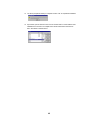
1.
Insert the Configuration Utility CD into an available CD-ROM. Run "D:\PC-OEM\
Utility\setup.exe" (where "D" represents a CD-ROM).
2.
It will show a wizard windows and then Click “Next”.
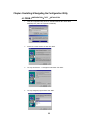
3.
You may click “Browse…” to change the install folder. Click “Next”.
4.
You may change the program folder. Click “Next”.
55
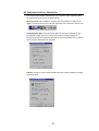
5.
The system will install utility files to the appropriate location. After the installation is
completed, the system shows a windows dialog. If you want to run the utility, select “Yes,
Launch…” and click “Finish”. Otherwise, click “Finish”.
56
4-2 CONFIGURATION UTILITY- NAVIGATION
The following section describes and defines the various functions of the Configuration Utility.
This utility provides quick access to all adapter settings.
Quick-Launch Icon: After installation is complete, launch the program and a utility icon will
appear in the “Quick-Launch” menu in the lower right hand corner of the screen, near the clock.
The Configuration Utility: Double clicking the utility icon in the Quick Launch bar will open
the Configuration Utility main menu, providing quick access to all adapter settings. The
following image shows the Configuration Utility with the “About” tab selected, here you will find
Version, Copyright and Manufacturer information.
Link Info: The Link Info menu provides information about the current link between the adapter
and the base station.
57
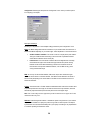
Configuration: Selecting this tab opens the “Configuration” menu. Here you will find options
for configuring your adapter.
Description of Settings
Following is an explanation of each adapter setting presented by the “Configuration” menu.
Mode: The Mode setting determines the architecture of your wireless LAN. Choose Ad-Hoc or
Infrastructure Mode depending on your network type. A brief explanation of each mode follows:
Ad-Hoc and 802.11b Ad-Hoc: This mode is used for a simple peer-to-peer network.
This type of network allows the sharing of local resources only between wireless
clients without a wireless Access Point (AP).
Infrastructure: This mode allows a wireless LAN to be integrated into an existing
wired network through an AP. Infrastructure type networks also permit roaming
between Access Points while maintaining connection to all network resources.
Infrastructure mode provides additional features, such as WEP security, power
saving and extended range.
SSID: An acronym for Service Set Identifier, SSID is the unique name shared among all
clients and Access Points in a wireless network. The SSID must be identical for all clients or
Access Points participating in the same network. The SSID is case sensitive and must not
exceed 30 characters.
Tx Rate: The transmit rate or Tx Rate selects the allowable transfer rates of the wireless client.
To optimize performance and range, the Tx Rate should be set to Fully Automatic, which will
automatically adjust the transfer speed for best performance and longest range.
Note: The Tx rate setting must be supported by the AP. If the AP does not support the Tx rate,
undesired results may occur.
PS Mode: Power Saving Mode enables or disables the power saving features of your wireless
adapter. When enabled on a laptop, the power saving mode can reduce power consumption
by the wireless card and extend the battery life of your laptop. This setting is only implemented
in a network operating in Infrastructure mode.
58
Changing the PS mode: The PS Mode on your adapter is set to “Disabled” by default.
To change the setting, select “Enabled” from the drop-down list, click “OK” and wait a
few seconds. The screen will then is updated and show the current Connection Status,
Link Quality and Signal Strength.
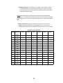
Channel: This setting specifies the default 802.11b channel used by the Wireless LAN
communication. In an Infrastructure type network without an Access Point active on the default
channel, clients will scan through all available channels searching for a network with matching
SSID.
Changing the Channel: Changing the channel is only effective in Ad-Hoc networks.
Networks operating in Infrastructure mode automatically scan for a channel. The
following table presents contains the operational channel frequency for several countries.
Regulatory Channel Frequency
Channel Frequency
FCC
Canada
ETSI
France
Spain
Japan
(MHz)
1
2412
ˇ
ˇ
ˇ
2
2417
ˇ
ˇ
ˇ
3
2422
ˇ
ˇ
ˇ
4
2427
ˇ
ˇ
ˇ
5
2432
ˇ
ˇ
ˇ
6
2437
ˇ
ˇ
ˇ
7
2442
ˇ
ˇ
ˇ
8
2447
ˇ
ˇ
ˇ
9
2452
ˇ
ˇ
ˇ
10
2457
ˇ
ˇ
ˇ
ˇ
ˇ
11
2462
ˇ
ˇ
ˇ
ˇ
ˇ
12
2467
ˇ
ˇ
13
2472
ˇ
ˇ
14
2484
ˇ
59
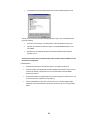
Encryption: Selecting the Encryption tab allows you to create new WEP keys.
NOTE : An acronym for Wired Equivalent Privacy, WEP is an encryption scheme used to
protect your wireless data communications. WEP uses a combination of 64-bit or 128-bit keys
to provide access control to your network and encryption security for every data transmission.
To decode a data transmission, each wireless client on the network must use an identical 64bit or 128-bit key. This feature is only available in Infrastructure Mode and must also be
enabled on the Access Point. Select the WEP tab to enable or disable this feature.
The 64-bit or 128-bit WEP keys can be generated from a user-defined passphrase (any text
string with a maximum of 32 characters) or a manual entry. To generate encryption keys for
each client communicating in the wireless network, complete the following steps:
1.
Select “Create with Passphrase” and type the exact same case sensitive text in the
Passphrase entry field for each client. Click “Apply” to change.
2.
Or, select “Manual Entry” and the “Default Tx Key” of four keys. Click “Apply” to change.
3.
Or, select “Manual Entry” and key in the ten hex values in the selected default key. Click
“Apply” to change.
4.
The 128-bit WEP only has a Tx key.
60
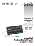
About :
61
Appendix A Troubleshooting
Problem Solving
My computer does not recognize the GL-241101.
Probable Solution:
The GL-241101 is not properly inserted into the PCMCIA slot.
Ensure that the GL-241101 has been inserted into an available PCMCIA slot.
The GL-241101 does not work properly.
Probable Solution:
Insert the PCMCIA Card into Notebook’s slot again. A beep should be heard if the
adapter is properly inserted.
Check the I/O cable that connects the RF module and the PCMCIA Card. The power LED
indicator will be active if the cable is properly connected.
For non-Windows 95/98 environments, ensure that a PCMCIA card service driver is
installed in your computer.
1) Click on the Control Panel and then on PC-Card. Check whether it has PCMCIA card
in one of the sockets or not. If you find PRISM2 IEEE 802.11 PC-Card Adapter in one of
the sockets, it means the card is detected properly. If you see the yellow sign of
question-mark(?), the resources are conflicting.
2)Right click on “My Computer” and the select Properties. Select the device Manager and
click on the Network Adapter. You will find PRISM2 IEEE 802.11 PC-Card Adapter if it is
installed successfully. If you see the Yellow sign the resources are conflicting. Click on
PCMCIA card and then on PCMCIA Card service, you can see the status of PCMCIA
card. If there are yellow sign either on adapter or PCMCIA card, please check followings.
2-1) Check if your Notebook supports 3.3V card.
2-2)Check if your Notebook has a free IRQ
62
2-3) Check that you have inserted the right card and have installed the proper driver.
If the GL-241101 does not function after attempting the above steps, remove the PCMCIA Card,
and do the following:
From the run window enter, c:\windows\system, locate and delete the cw10.sys file
Open the “Control Panel” double-click “System” and delete PRISM2 IEEE 802.11 PCcard Adapter.
Restart the PC and repeat the hardware and software installation steps outlined in
Chapters 3 and 4.
The GL-241101 station cannot communicate with other computers linked via Ethernet in the
Infrastructure configuration.
Probable Solution:
Ensure that the GL-241101 with which the station is associated is powered on.
Confirm the station is configured with the same operating radio channel as the GL-241101.
If the IDs are different, change the GL-241101 and all the stations within the BSS to
another radio channel.
Ensure that the station is configured with the same security options as the GL-241101, and
can be turned off and on with the same security key.
Confirm that the BSS ID is the same as the GL-241101 for a roaming disabled station.
Alternately confirm that the ESS ID is the same as the GL-241101 for a roaming enabled
station.
63
Appendix B Glossary
Access Point - An internetworking device that seamlessly connects wired and wireless networks together.
Ad-Hoc - An Ad-Hoc wireless LAN is a group of computers each with wireless adapters, connected as an
independent wireless LAN without an access point to make point-to-point wireless communication.
ATIM – It means "Announcement Traffic Indication Message". A station may enter power save mode if and only if
the value of the ATIM Window in use within the IBSS (in Ad hoc mode) is greather than zero. If this
value is NULL, no power management is used within IBSS created by the station.
Authentication Type – The Authentication Type controls the WEP key validation during the authentication of
a station by the access point. When the Shared Key option is selected, the access point will validate that
the station is using the same WEP key with it. This procedure goes like this: the access point sends a
known unencrypted packet to the station. The station encrypts this packet and sends it back to the
access point. The access point tries to decrypt this packet and then sends an Authentication response
packet to the station indicating the success or failure of this process. On the other hand, under Open
Authentication, there is no check for a matching WEP key.
Backbone - The core infrastructure of a network, the portion of the network that transports information from one
central location to another central location. The information is then off-loaded onto a local system.
Base Station - In mobile telecommunication, a base station is the central radio transmitter/ receiver that
maintains communication with the mobile radio telephone sets within range. In cellular and personal
communications applications, each cell or microcell has its own base station; each base station in turn
is interconnected with other cells’ base.
BSS - Stands for “Basic Service Set.” An Access Point associated with several wireless stations.
ESS - Stands for “Extended Service Set.” More than one BSS can be configured as an Extended Service Set. An
ESS is basically a roaming domain.
Ethernet - A popular local area data communications network, originally developed by Xerox Corp., which
accepts transmission from computers and terminals. Ethernet operates on 10 Mbps baseband
transmission over shielded coaxial cable or over shielded twisted pair telephone wire.
Fragmentation Threshold – The Fragmentation Threshold defines the number of bytes used for the
fragmentation boundary for directed messages. The purpose of "Fragmentation Threshold" is to
increase the transfer reliability thru cutting a MAC Service Data Unit (MSDU) into several MAC Protocol
Data Units (MPDU) in smaller size. The RF transmission can not allow to transmit too big frame size due
to the heavy interference caused by the big size of transmission frame. But if the frame size is too small,
it will create the overhead during the transmission.
Infrastructure - An integrated wireless and wired LAN system is called an Infrastructure configuration.
Listen Interval – The Listen Interval field is used to indicate to the AP how often a station wakes to listen to
Beacon managemetn frames. The value of this parameter is the station's Listen Interval MIB attribute
and is expressed in units of Beacon Interval. The length of the Listen Interval decides the wake up time
to listen to Beacon management. Longer Listen Interval decreases the performance and shorter interval
decreases power saving function.
PCMCIA - Personal Computer Memory Card International Association, which develops standards for PC cards,
formerly known as PCMCIA cards, are available in three “types” which are about the same length and
width as credit cards, but range in thickness from 3.3 mm (Type I) to 5.0 mm (Type II) to 10.5 mm (Type
64
III). These cards can be used for many functions, including memory storage, as landline modems and
as wireless LAN.
Preamble Mode – Preamble is a sequence of bits transmitted at 1Mbps that allows the PHY circuitry to reach
steady-state demodulation and synchronization of bit clock and frame start. Two different preambles and
headers are defined: the mandatory supported Long Preamble and header, which interoperates with the
1 Mbit/s and 2 Mbit/s DSSS specification (as described in IEEE Std 802.11), and an optional Short
Preamble and header (as described in IEEE Std 802.11b). At the receiver, the Preamble and header are
processed to aid in demodulation and delivery of the PSDU. The Short Preamble and header may be
used to minimize overhead and, thus, maximize the network data throughput. However, the Short
Preamble is supported only from the IEEE 802.11b (High-Rate) standard and not from the original IEEE
802.11. That means that stations using Short-Preamble cannot communicate with stations implementing
the original version of the protocol.
Roaming - A function that allows one to travel with a mobile end system (wireless LAN mobile station, for
example) through the territory of a domain (an ESS, for example) while continuously connecting to the
infrastructure.
RTS Threshold – Transmitters contending for the medium may not hear each other. The RTS (Request To
Send) Threshold defines the number of bytes used for the RTS/CTS (Clear to Send) handshake
boundary. The small setup value will cause the overhead during the transmission and too big setup
value will decrease the transfer reliability. So normally the value should be default in 2432 bytes. By
inconsistent data flow, try to minor the value. The RTS/CTS mechanism can solve this “ Hidden Node
Problem”.
WEP – Wired Equivalent Privacy (Wep) is an encryption scheme used to protect wireless data communication.
Selecting “Disabled” will prevent you from sharing data with other computers if your network uses Wep.
If your network is Wep enabled, you must choose “64 bits” or “128 bits”. Consult your System
Administrator for more information about your network type. For more information about Wep, see the
chapter entitled “PRISM Configuration Utility” in this manual.
65