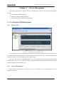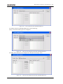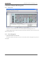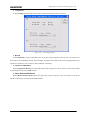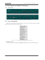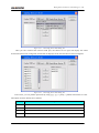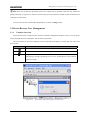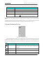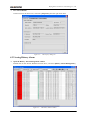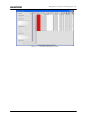
1
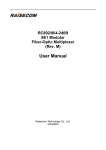
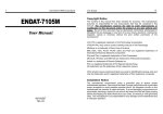
RC003COMM (RC004-16) EMS
User Manual
RC-A043-V27-050909-EN
Beijing Raisecom Science & Technology Co., Ltd.
Copyright © 2005 Raisecom Company
Legal Notices
Beijing Raisecom Science & Technology Co., Ltd makes no warranty of any kind with regard to this
manual, including, but not limited to, the implied warranties of merchantability and fitness for a particular
purpose. Beijing Raisecom Science & Technology Co., Ltd shall not be held liable for errors contained
herein or direct, indirect, special, incidental or consequential damages in connection with the furnishing,
performance, or use of this material.
Warranty
A copy of the specific warranty terms applicable to your Raisecom product and replacement parts can be
obtained from Service Office.
Restricted Rights Legend
All rights are reserved. No part of this document may be photocopied, reproduced, or translated to another
language without the prior written consent of Beijing Raisecom Science & Technology Co., Ltd. The
information contained in this document is subject to change without notice.
Copyright Notices
Copyright ©2005 Raisecom. All rights reserved.
No part of this publication may be excerpted, reproduced, translated or utilized in any form or by any means,
electronic or mechanical, including photocopying and microfilm, without permission in Writing from
Beijing Raisecom Science & Technology Co., Ltd.
Trademark Notices
is the trademark of Beijing Raisecom Science & Technology Co., Ltd.
Java™ is a U.S. trademark of Sun Microsystems, Inc.
Microsoft® is a U.S. registered trademark of Microsoft Corporation.
Windows NT® is a U.S. registered trademark of Microsoft Corporation.
Windows® 2000 is a U.S. registered trademark of Microsoft Corporation.
Windows® XP is a U.S. registered trademark of Microsoft Corporation.
Windows® and MS Windows® are U.S. registered trademarks of
Microsoft Corporation.
Contact Information
Technical Assistance Center
The Raisecom TAC is available to all customers who need technical assistance with a Raisecom product,
technology or solution. You can communicate with us through the following methods:
Add:
1120, Haitai Tower, 229 Fourth North Loop Middle Road, Haidian District,
Beijing 100083
Tel:
+86-10-82884499 Ext.878 (International Department)
Fax:
+86-10-82885200, +86-10-82884411
World Wide Web
You can access the most current Raisecom product information on the World Wide Web at the following
URL:
http://www.raisecom.com
Feedback
Comments and questions about this manual are welcomed. Please review the FAQ in the related manual, and
if your question is not covered, send email by using the following web page:
http://www.raisecom.com/en/xcontactus/contactus.htm.
If you have comments on the EMS specification, instead of the web page above, please send
comments to:
[email protected]
We hope to hear from you!
Beijing Raisecom Science & Technology Co., Ltd
CONTENTS
PREFACE ................................................................................................................................................ 1
ABOUT THIS MANUAL........................................................................................................................... 1
WHO SHOULD READ THIS MANUAL ..................................................................................................... 1
COMPLIANCE ......................................................................................................................................... 1
CHAPTER 1
OVERVIEW ................................................................................................................ 3
1.1
FUNCTION OVERVIEW ................................................................................................................. 3
1.2
PRODUCT MODELS ...................................................................................................................... 3
CHAPTER 2
2.1
DEVICE MANAGEMENT........................................................................................ 6
1U STANDALONE PDH MANAGEMENT ....................................................................................... 6
2.1.1
Device View ...................................................................................................................... 6
2.1.2
Device Management.......................................................................................................... 6
2.1.3
Subcard Managment........................................................................................................ 12
2.2
RC004-16 MODULAR PDH MANAGEMENT .............................................................................. 15
2.2.1
Device View .................................................................................................................... 15
2.2.2
Device Management........................................................................................................ 15
2.3
PCM COMPREHENSIVE MULTIPLEXER MANAGEMENT ............................................................. 19
2.3.1
Device View .................................................................................................................... 19
2.3.2
Device Management........................................................................................................ 19
2.3.3
Subcard Managment........................................................................................................ 27
CHAPTER 3
3.1
OPERATING AND MAINTENANCE.................................................................... 28
RC004-16 ELEMENT MANAGMENT .......................................................................................... 28
3.1.1
Trap Receipt Configuration ............................................................................................. 29
3.1.2
System Information Configuration.................................................................................. 30
3.1.3
E1 Line Information ........................................................................................................ 30
3.1.4
Name Remote Device...................................................................................................... 33
3.1.5
System Command............................................................................................................ 34
3.1.6
Data List .......................................................................................................................... 35
3.2
PC COM PORT MANAGEMENT ................................................................................................. 37
3.2.1
Trap Configuration .......................................................................................................... 38
3.2.2
System Information Configuration.................................................................................. 38
3.2.3
E1 Line Details ................................................................................................................ 38
3.2.4
Name Remote Device...................................................................................................... 38
3.2.5
COM Port Configuration................................................................................................. 38
3.3
DEVICE BROWSER TREE MANAGEMENT ................................................................................... 43
RC003COMM(RC004-16) EMS User Manual
I
Beijing Raisecom Science & Technology Co., Ltd
3.3.1
Function Overview .......................................................................................................... 43
3.3.2
Specific Operation ........................................................................................................... 44
3.4
CONTROL TOOL BAR ON THE VIEW .......................................................................................... 45
CHAPTER 4
ALARM AND EVENT MANAGEMENT .............................................................. 47
4.1
VIEWING CURRENT ALARM ...................................................................................................... 47
4.2
VIEWING HISTORY ALARM........................................................................................................ 48
APPENDIX A
ALARM TYPE ........................................................................................................ 51
APPENDIX B
ABBREVIATION LIST.......................................................................................... 57
RC003COMM(RC004-16) EMS User Manual
II
Beijing Raisecom Science & Technology Co., Ltd
Preface
About This Manual
This manual introduces primary functions of the configuration management software for RC series
products.
Who Should Read This Manual
Sales and marketing engineers, after service staff and telecommunication network design engineers
could use this manual as a valuable reference. If you want to get an overview on features, applications,
architectures and specifications of Raisecom RC series integrated access devices, you could find useful
information in this manual as well.
Compliance
The RC series products developed by Raisecom are strictly complied with the following standards as
well as ITU-T, IEEE, IETF and related standards from other international telecommunication standard
organizations:
YD/T900-1997 SDH Equipment Technical Requirements - Clock
YD/T973-1998 SDH 155Mb/s and 622Mb/s Technical conditions of optical transmitter module and
receiver module
YD/T1017-1999 Network node interface for the Synchronous Digital Hierarchy (SDH)
YD/T1022-1999 Requirement of synchronous digital hierarchy (SDH) equipment function
YD/T1078-2000 SDH Transmission Network Technique Requirements-Interworking of Network
Protection Architectures
YD/T1111.1-2001
Technical
Requirements
of
SDH
Optical
Transmitter/Optical
Receiver
Modules——2.488320 Gb/s Optical Receiver Modules
YD/T1111.2- 2001 Technical Requirements of SHD Optical Transmitter/Optical Receiver
Modules——2.488320 Gb/s Optical Transmitter Modules
YD/T1179- 2002 Technical Specification of Ethernet over SDH
G.703 Physical/electrical characteristics of hierarchical digital interfaces
G.704 Synchronous frame structures used at 1544, 6312, 2048, 8448 and 44 736 kbit/s hierarchical
levels
G.707 Network node interface for the synchronous digital hierarchy (SDH)
G.774 Synchronous digital hierarchy (SDH) - Management information model for the network element
view
G.781 Synchronization layer functions
G.783 Characteristics of synchronous digital hierarchy (SDH) equipment functional blocks
RC003COMM(RC004-16) EMS User Manual
1
Beijing Raisecom Science & Technology Co., Ltd
G.784 Synchronous digital hierarchy (SDH) management
G.803 Architecture of transport networks based on the synchronous digital hierarchy (SDH)
G.813 Timing characteristics of SDH equipment slave clocks (SEC)
G.823 The control of jitter and wander within digital networks which are based on the 2048 kbit/s
hierarchy
G.825 The control of jitter and wander within digital networks which are based on the synchronous
digital hierarchy (SDH)
G.826 End-to-end error performance parameters and objectives for international, constant bit-rate
digital paths and connections
G.828 Error performance parameters and objectives for international, constant bit-rate synchronous
digital paths
G.829 Error performance events for SDH multiplex and regenerator sections
G.831 Management capabilities of transport networks based on the synchronous digital hierarchy
(SDH)
G.841 Types and characteristics of SDH network protection architectures
G.842 Interworking of SDH network protection architectures
G.957 Optical interfaces for equipments and systems relating to the synchronous digital hierarchy
G.691 Optical interfaces for single channel STM-64 and other SDH systems with optical amplifiers
G.664 Optical safety procedures and requirements for optical transport systems
I.731 ATM Types and general characteristics of ATM equipment
I.732 ATM Functional characteristics of ATM equipment
IEEE 802.1Q Virtual Local Area Networks (LANs)
IEEE 802.1p Traffic Class Expediting and Dynamic Multicast Filtering
IEEE 802.3 CSMA/CD Access Method and Physical Layer Instruction
RC003COMM(RC004-16) EMS User Manual
2
Beijing Raisecom Science & Technology Co., Ltd
Chapter 1
Overview
This chapter describes the architectures and functions of RC003COMM(RC004-16) EMS, and consists
of the following sections:
Function overview
Product models
1.1 Function Overview
RC003COMM(RC004-16) EMS (Element Management System) provides GUI for device
management. A device view generated by the EMS is identical with appearance of the real device. In
addition, that view could truly reflect current status of the device, so you can monitor and maintain the
device in a centralized and quick way.
RC003COMM(RC004-16) EMS enables you to manage RC003 standalone PDH, RC004-16 Modular
PDH and RC3000 PCM comprehensive Multiplexer.
RC003COMM(RC004-16) EMS supports two management modes. The first mode enables you to
manage devices connected to COM ports on a PC through the Agent software running on the PC. At present,
you can manage up to 16 COM ports in this mode, and each port can connect 1 to 40 devices depending on
the type of those connected devices. The manageable devices in this mode cover 1U standalone PDH. The
second mode enables you to manage PDH modules through the Agent software running on the RC004-16
NMS master control card which is plugged in Slot 0 of Chassis 1. Slot 1 to 15 could be used to insert PDH
modules. One Agent software could manage up to 4 10U big chassis.
1.2 Product Models
Table 1-1
Standalone PDH Product Model Table
Serial Number
Product Model Identification
1
RC801-240B(REV.B) Dual-strand PDH
2
RC803-240B(REV.B) Single-strand PDH, 1310 nm TX
3
RC805-240B(REV.B) Single-strand PDH, 1550 nm TX
4
MS2104-240(REV.B) Dual-strand PCM
5
MS2304-240(REV.B) Single-strand PCM, 1310 nm TX
6
MS2504-240(REV.B) Single-strand PCM, 1550 nm TX
7
RC801-480B(REV.A) Dual-strand PDH
8
RC803-480B(REV.A) Single-strand PDH, 1310 nm TX
9
RC805-480B(REV.A) Single-strand PDH, 1550 nm TX
10
RC801-120C(REV.A) Dual-strand PDH
11
RC803-120C(REV.A) Single-strand PDH, 1310 nm TX
12
RC805-120C(REV.A) Single-strand PDH, 1550 nm TX
RC003COMM(RC004-16) EMS User Manual
3
Beijing Raisecom Science & Technology Co., Ltd
13
RCMS2104-120(REV.A) Dual-strand PCM
14
RCMS2304-120(REV.A) Single-strand PCM, 1310 nm TX
15
RCMS2504-120(REV.A) Single-strand PCM, 1550 nm TX
16
RC801-240B(REV.M) Dual-strand PDH
17
RC803-240B(REV.M) Single-strand PDH, 1310 nm TX
18
RC805-240B(REV.M) Single-strand PDH, 1550 nm TX
19
RC801-120B(REV.M) Dual-strand PDH
20
RC803-120B(REV.M) Single-strand PDH
21
RC805-120B(REV.M) Single-strand PDH
22
RC801-480B(REV.M) Dual-strand PDH
23
RC803-480B(REV.M) Single-strand PDH
24
RC805-480B(REV.M) Single-strand PDH
Table 1-2
RC004-16 Product Model Table
Serial Number
Product Model Identification
1
RC802-240B(REV.B) Dual-strand PDH module
2
RC804-240B(REV.B) Single-strand PDH module
3
RC802-120BX2(REV.B) Dual-strand PDH module
4
RC804-120BX2(REV.B) Single-strand PDH module
5
RC802-240B(REV.C)+RC802-240BS(REV.A) Dual-strand PDH module
6
RC804-240B(REV.C)+RC802-240BS(REV.A) Single-strand PDH module
7
RCMS2204-240(REV.A) Dual-strand PCM module
8
RCMS2404-240(REV.A) Single-strand PCM module
9
RC802-240B(REV.C) Dual-strand PDH module
10
RC804-240B(REV.C) Single-strand PDH module
11
RC802-240B(REV.M) Dual-strand PDH module
12
RC804-240B(REV.M) Single-strand PDH module
13
RC802-120B*2(REV.M) Dual-strand PDH module
14
RC804-120B*2(REV.M) Single-strand PDH module
15
RC802-240B(REV.M)+RC802-240BS(REV.M) Dual-strand PDH module
16
RC804-240B(REV.M)+RC802-240BS(REV.M) Single-strand PDH module
17
RC802-120B(REV.M) Dual-strand PDH module
18
RC804-120B(REV.M) Single-strand PDH module
RC003COMM(RC004-16) EMS User Manual
4
Beijing Raisecom Science & Technology Co., Ltd
Table 1-3
The Line Cards supported by Current PCM Comprehensive Multiplexer Table
Serial Number
Product Model Identification
1
8M Optical Line Card
2
2E1 Line Card (with ADM)
3
2E1 Line Card (without ADM)
4
4E1 Line Card
Table 1-4
The User Cards Supported by Current PCM Comprehensive Multiplexer
Serial Number
Product Model Identification
1
8-Channel FXS User Card
2
8-Channel FXO User Card
3
8-Channel FXS&FXO Mixed User Card
4
8-Channel EM2 User Card
5
4-Cannel EM4 User Card
6
Single-Channel V35 User Card
7
Single-Channel V24 User Card
8
10MBase-T Ethernet User Card
9
RS232 Asynchronized Communication User Card
10
RS422 Asynchronized Communication User Card
11
Magnet Telephone Card
RC003COMM(RC004-16) EMS User Manual
5
Beijing Raisecom Science & Technology Co., Ltd
Chapter 2
Device Management
This chapter describes the functions and service management of device, and consists of the following
sections:
1U standalone PDH management
RC004-16 modular PDH management
PCM comprehensive Multiplexer management
2.1 1U Standalone PDH Management
2.1.1
Device View
Figure 2-1
The Device View of Standalone PDH
As the figure shows above, the chassis tree and device view are located on the left side and right side of
the window respectively. Double click a chassis node beneath the chassis tree, the view for front panel and
rear panel of this device will be displayed in the right tab page.
The view area could accommodate multiple views. When there’re more than one window opened
simultaneously, user can access each view simply by double clicking the relevant tab, and the one will be
bulged for displaying the intended view.
2.1.2
Device Management
Right click the front panel or rear panel, you’ll see a menu listing several items popup. Here’s an
example of this menu:
RC003COMM(RC004-16) EMS User Manual
6
Beijing Raisecom Science & Technology Co., Ltd
Figure 2-2
The right click menu
Select [Interface Info] from the right click menu to launch the Interface Information dialog box,
which provides access to the information like LOS Status, LOF Status, Loop Status and so on. The following
figure is an example of this window:
Figure 2-3
The Interface Information dialog box
LNote: The Interface Information dialog box launched from the front panel only displays information of
E1 lines within basic subsystems, the information of expansion cards would be displayed in the dialog box
launched from subcards.
Configuration
Select <Config> from the right click menu, a Config Management dialog box similar to the following
will appear. From it, you can make configuration for the alarm and fiber port.
RC003COMM(RC004-16) EMS User Manual
7
Beijing Raisecom Science & Technology Co., Ltd
Figure 2-4
The Config Management interface
Loop Test
Select [Loop Test] from the right click menu, you will see a Config Management dialog box popup. It
enables you to make relevant configuration for loop test.
Figure 2-5
The Loop Test interface
To do so, you need:
Firstly, select the module type to be configured.
Figure 2-6
The Loop Test configuration procedure
LNote: The <Config> button will be disable if this item is not specified.
After you have selected the module type, its relevant E1 Line will appear in the E1 Loop Config drop
down menu. In this way, the <Config> button is enable.
RC003COMM(RC004-16) EMS User Manual
8
Beijing Raisecom Science & Technology Co., Ltd
Figure 2-7
The Loop Test configuration procedure
Next, select a loop item for E1 line.
Figure 2-8
The Loop Test configuration procedure
Click <Config> to apply the configuration.
Figure 2-9
The Loop Test configuration procedure
At last, when you complete configuration, click <Close> to exit this dialog box.
LNote: The Loop Test dialog box for RCMS Ethernet Multiplexer is differing from the preceding one, it
can be used for configuring more than one line loop simultaneously. Here’s an example of this window:
RC003COMM(RC004-16) EMS User Manual
9
Beijing Raisecom Science & Technology Co., Ltd
Figure 2-10
The Loop Test interface of RCMS-2000 Device
To perform loop test for RCMS-2000 device, do the following:
Firstly, select the module type to be configured.
Figure 2-11
The Loop Test configuration procedure of RCMS-2000 Device
Secondly, select the lines to be configured in “Normal” and “Loop” status.
Figure 2-12
The Loop Test configuration procedure of RCMS-2000 Device
RC003COMM(RC004-16) EMS User Manual
10
Beijing Raisecom Science & Technology Co., Ltd
Table 2-1
The descriptions for each button available on the window
Item
Description
>
Move selected item(s) from left list to right list.
<
Move selected item(s) from right list to left list.
>>
Move all item(s) from left list to right list.
<<
Move all item(s) from right list to left list.
Thirdly, configure loop or normal settings for the E1 line.
At last, when you finish configuration, click the <Close> button to exit this dialog box.
Refresh
Select [Refresh] from the right click menu to perform refresh operation, the current device view will
turn to latest status correspondingly. When Trap messages from the device cannot be received appropriately,
this operation is useful for user to monitor that device real-timely.
Open Remote Device View
Select [Remote Device] from the right click menu to open the views for remote device. You will see a
prompt message appear when this selected one is not connected.
Figure 2-13
The Hint message
LNote: This function is only available in standalone PDH of REV.M version.
Save Configuration
Select [Save Config] from the right click menu to apply configuration for this device. When restart
after power off, the device will resume to its previously saved configuration automatically. For example,
when enable the “Alarm Sound Output” feature and perform “Save Config” operation, after you turn off and
restart the device, the “Alarm Sound Output” item will be still in enable state.
Clear Configuration
This function is only available in standalone PDH of REV.M version.
Select [Clear Config] from the right click menu to perform clearance operation. Thus the device will
not perform reconfiguration after restart, and will resume to settings preconfigured at factory automatically.
RC003COMM(RC004-16) EMS User Manual
11
Beijing Raisecom Science & Technology Co., Ltd
Refresh Chassis Temperature
Double click the temperature icon presented on rear panel view, the temperature value of current device
will update simultaneously, as the figure shows below:
Figure 2-14
2.1.3
Refreshing chassis temperature
Subcard Managment
Subcard Model
The device with expansion slot(s) currently supports 4 kinds of expansion cards, they are:
Table 2-2
Expansion Card Model Table
Serial
Model
Number
Number
1
1
Expansion Card Model
Description
Extended E1
Count
SUBM-4E1(REV.A) 4E1 Line Sub-module
Unintelligent
4
Card
2
16
SUBM-E(REV.A) Ethernet Sub-module
Intelligent
1
Card
3
20
SUBM-E(REV.B) Ethernet Sub-module
Intelligent
1
Card
4
19
SUBM-FV35(REV.A) Frame, V35 Sub-
Intelligent
module
Card
1
The extended E1 Line number may be varying when plugging different expansion cards into expansion
slots. The corresponding relationships between them are as follows:
Table 2-3
The Subcard Model Corresponding to Line Number of Expansion Card
Expansion Card Model
E1 Line Sequence (Slot
E1 Line Sequence (Slot
1)
2)
SUBM-4E1(REV.A) 4E1 Line Sub-module
5, 6, 7, 8
8, 7, 6, 5
SUBM-E(REV.A) Ethernet Sub-module
5
8
SUBM-E(REV.B) Ethernet Sub-module
5
8
SUBM-FV35(REV.A) Frame, V35 Sub-module
5
8
RC003COMM(RC004-16) EMS User Manual
12
Beijing Raisecom Science & Technology Co., Ltd
Table 2-4
The Views of Expansion Cards in Support
Expansion Card Model
View
SUBM-4E1(REV.A) 4E1 Line Sub-module
SUBM-E(REV.A) Ethernet Sub-module
SUBM-E(REV.B) Ethernet Sub-module
SUBM-FV35(REV.A) Frame, V35 Sub-module
Table 2-5
SUBM-E Indicator Table
Indicator
LAL
Description
Indicates alarm status at local side. It represents “or” relationship among LOF, CRC
and AIS. When one of these has alarm generated, the LAL indicator turns to “Red”;
when there’re no alarms generated among the three, it presents “Dark Red”.
RLP
Indicates loop status of remote module. When the module is looping toward remote
side, this indicator turns to “Yellow”, otherwise it presents “Dark Yellow”.
RAL
Indicates alarm status of remote module. When the module working on remote device
has any type of alarm generated, this indicator will turns to “Red”, when there’re no
alarms generated, it presents “Dark Red”.
LNK
Indicates LINK state of Ethernet interface on local module. When LINK UP, this
indicator presents “Green”; otherwise (LINK DOWN), it presents “Dark Green”.
FDX:
Indicates duplex state. When the duplex state of Ethernet interface on this module is
configured as Full Duplex, this indicator presents “Green”, otherwise (Half Duplex),
it presents “Dark Green”.
Table 2-6
SUBM-FV35 Indicator Table
Identification
Description
LAL
Its meaning and status are identical with those of LAL indicator on SUBM-E module.
RAL
Its meaning and status are identical with those of RAL indicator on SUBM-E module.
Subcard Operation
Select a card and right click, you will get a menu displaying several items. From this menu, you can:
RC003COMM(RC004-16) EMS User Manual
13
Beijing Raisecom Science & Technology Co., Ltd
Figure 2-15
The right click menu available on the expansion card
1. View card information
Select [Card Information] item, the Card Information dialog box will popup for displaying related
information:
Figure 2-16
The Card Information dialog box
2. Configuration
Select [Config] item, the Config Management dialog box will be displayed as follow:
Figure 2-17
The Config Management dialog box for expansion subcard
3. Refresh
Select [Refresh] item, the card type and indicators on it will update simultaneously.
RC003COMM(RC004-16) EMS User Manual
14
Beijing Raisecom Science & Technology Co., Ltd
2.2 RC004-16 Modular PDH Management
2.2.1
Device View
Figure 2-18
The Device View of RC004-16 device
Double click a node beneath the chassis tree on left to open the corresponding chassis view.
If some a chassis view has already been opened, when double clicking this node, the relevant tab will
bulge for displaying the view.
2.2.2
Device Management
Operations On Master Network Card
The Master Network Card resides in the slot 0 of first chassis. Select it and right click, you’ll see a
menu popup:
RC003COMM(RC004-16) EMS User Manual
15
Beijing Raisecom Science & Technology Co., Ltd
Figure 2-19 The right click menu available on the master control card
The [Trap Config] and [System Config] item are also available from the menu bar on top of the EMS
window. See relevant description in this manual for details.
Select [Refresh] item to refresh the state of ALM indicator on master network card. The ALM indicator
is used to identify if there’re alarms generated on current chassis. If there are, the indicator will turn to “red”,
otherwise it will be in “gray”. The alarm indicator will take effective only in case you configure the “Chassis
Alarm” item to be enabled in “System Config”.
Operations On PDH Module
The following section describes operations on modular PDH by taking RC804-120B*2(REV.M) as
example. The panel of RC804-120B*2(REV.M) comprises two parts, the Up PDH and Down PDH.
Figure 2-20 The demonstration of PDH module
Select a card from the slots labeled from 1 to 15 on RC004-16 chassis, you’ll see a menu shown in
RC003COMM(RC004-16) EMS User Manual
16
Beijing Raisecom Science & Technology Co., Ltd
below appear:
Figure 2-21
The right click menu available on the PDH module
1. Interface Information
Select [Interface Information] from the right click menu to launch the Show Interface Information
dialog box.
Figure 2-22
The Show Interface Information dialog box
Where the Desc table at lower section of this window displays a list of information for selected card,
including Module (Up or Down), Local/Remote, Interface Type (E1 port or Optical Port), Loop Status,
Alarm Status and so forth.
RC003COMM(RC004-16) EMS User Manual
17
Beijing Raisecom Science & Technology Co., Ltd
2. Cofiguration
Select [Config] from the right click menu to launch the dialog box show in below.
Figure 2-23
The Config interface
3. Refresh
Select [Refresh] from the right click menu to perform refresh operation, the current view will turn to
latest status correspondingly. When Trap messages from that card could not be received appropriately, this
operation is useful for user to observe alarm indicator real-timely.
4. Up Remote PDH Device
Select [Up Remote Device] from the right click menu to open the view for remote 1U device(s) linked
to optical port of up remote PDH module.
5. Down Remote PDH Device
Select [Down Remote Device] from the right click menu to open the view for remote 1U device(s)
linked to optical port of down remote PDH module.
RC003COMM(RC004-16) EMS User Manual
18
Beijing Raisecom Science & Technology Co., Ltd
2.3 PCM Comprehensive Multiplexer Management
2.3.1
Device View
Figure 2-24
2.3.2
The view of PCM Comprehensive Multiplexer
Device Management
Right click on front panel or rear panel of the device, you will see a menu shown in figure 2-25 appear.
Select one of the items to perform relevant operation.
Figure 2-25
The right click menu launched from the front or rear panel
Hardware Version
The operation interface launched by the [Hardware Version] item is similar to the following figure:
RC003COMM(RC004-16) EMS User Manual
19
Beijing Raisecom Science & Technology Co., Ltd
Figure 2-26
The Device Version dialog box
Table 2-7 Description of information available on this interface
Object
Description
Device ID
The device’s serial number, with a value between 1-40
Device Type
The type identification of managed device
Hardware Version
The hardware version of this device
Software Version
The application version of the Single Chip Micyoco
Chassis Configuration
The operation interface launched by the [Chassis Config] item is similar to the following figure:
Figure 2-27
The chassis configuration interface
E1 Line Configuration
The E1 line configuration feature is used to view and configure information of E1 line, including E1
port useable, frame mode, and controls on various alarm outputs. It enables you to configure one or more
lines at one time.
To perform configuration, do the following:
Firstly, select [E1 Config] from the right click menu available on device panel, you will see a window
similar to the following popup.
RC003COMM(RC004-16) EMS User Manual
20
Beijing Raisecom Science & Technology Co., Ltd
Figure 2-28 The E1 Line configuration interface
Next, select a row of information to be modified, and click the <Modify> button to enter the Modify
dialog box.
Figure 2-29
The E1 information configuration interface
When select more than one line for modification, the window will be like this:
RC003COMM(RC004-16) EMS User Manual
21
Beijing Raisecom Science & Technology Co., Ltd
Figure 2-30
LNote:
The Batch Modify dialog box
1. The number of E1 line is determined by the type of Line Interface Card.
2. The cross information and alarm outputs of the E1 line can be configurable only when the line
is enabled.
3. Alarm Output Control is the master switch of E1 alarm outputs. Only when this function is
enabled that the remainder of outputs could take effective.
Finally, after you finish configuration, click the <Save> button to apply the modification, or click
<Close> button to quit without any change.
Cross Configuration
Click <Cross Config> from the right click menu, you will see a dialog box similar to the following
appear:
RC003COMM(RC004-16) EMS User Manual
22
Beijing Raisecom Science & Technology Co., Ltd
Figure 2-31 The Cross Configuration dialog box
Description of Cross Configuration interface
As the figure shows above, the Cross Configuration dialog box consists of two tables, the In Line
Cross table and Out Line Cross table. They are respectively located on left side and right side of this
window. Where the In Line Cross table is intended to indicate if there is incoming cross data, and which
channel of line they’re sourcing from, while the Out Line Cross table presents the same information for
outgoing cross data.
The previous window contains a column named “Cross Mode”, whose detailed implication are listed in
the following table:
Table 2-8 The Implication of Cross Mode Icon
Icon
Implication
The channel has incoming cross data delivered.
The channel has outgoing cross data delivered.
The channel has bi-directional cross data delivered, i.e. it has both
incoming cross data and outgoing cross data.
The channel has no cross data delivered on it.
Not all types of line are crossable at present. The following table gives out crossable lines in support by
current version:
Table 2-9 The Cross Line Type
Serial Number
Incoming Line
Outgoing Line
Crossable
1
E1 Line
E1 Line
Yes
2
E1 Line
User Line
Yes
3
User Line
E1 Line
Yes
RC003COMM(RC004-16) EMS User Manual
23
Beijing Raisecom Science & Technology Co., Ltd
4
User Line
User Line
No
Plus, the Cross table contains a column of “Cross State”, which is used to identify the context of cross
data. In In Line Cross table, it represents the source of existing cross data within specific channel, i.e. which
channel belonging to which line it comes from; while in Out Line Cross table, it presents where the existing
cross data transfer to, i.e. transfer these data to which cannel within which line.
For description on each control of Cross Configuration interface, refer to the following table:
Table 2-10 The Controls available on Cross Configuration dialog box
Object
Description
Unidirection
When this item is selected, the system will do incoming cross configuration for
selected incoming line.
Bidirection
When this item is selected, the system will do incoming cross configuration for
both incoming channels and outgoing channels. It servers as bi-directional
configuration.
Auto Delete
When this item is selected, for instance, to configure bi-directional cross for
Channel A and Channel B, if the Channal A already has cross data outgoing to
Channel C, the system will automatically delete these outgoing cross data (A-
>C), and establish bi-directional cross between Cannel A and B (A<->B);
Otherwise, besides establishing bi-directional cross (A<->B), the previous
outgoing cross (A->C) will not be deleted.
Raw Data
When this item is selected, the data in cross table will be displayed as original
data, and the type of line and chanel will not be displayed.
Refresh
Obtain latest data from device and update the Incoming and Outgoing Cross
tables.
Cross
This button is used to initiate cross configuation for channels of selected lines.
Delete
Remove the existing cross data.
Close
Clicking this button will exit the configuration interface.
LNote: Your system only allows one incoming cross data staying in each channel of line. When configure
incoming cross or bi-directional cross for a channel with existence of incoming cross, the system will delete
previous incoming cross data, and replace it with new one.
RC003COMM(RC004-16) EMS User Manual
24
Beijing Raisecom Science & Technology Co., Ltd
Figure 2-32 The appearance of Cross Configuration interface when Raw Data option is selected
LNote: In the “Cross State” column of preceding figure, the line number from 1-4 presents E1 line,
and the scope of 5-8 presents user line.
Cross Operation
Select successive rows with equivalent amount in both In Line and Out Line Cross tables. Then select
<Unidirection> or <Bidirection> option, as well as the <Auto Delete> option as applicable. After you
complete selection, click the <Cross> button.
LNote:
1. If the rows you selected from both Incoming and Outgoing Line Cross tables are not
successive, the cross configuration could not be performed.
2. If the amount of selected rows in both tables are not consistent, the cross configuration could
not be performed as well.
3. In case of no rows selected in the Incoming and Outgoing Line Cross tables, or rows in the
two are all selected, the system will perform cross configuration for current lines in both tables by crossing
the corresponding channels from top to bottom.
Delete Operation
Select the row(s) to be deleted from the In Line Cross table and click the <Delete> button. At this time,
the system will give a Confirm dialog box for your confirmation. Click <Yes> to perform deletion
operation.
LNote: Select row(s) in the Incoming Line Cross table, thus you can delete the intended rows.
RC003COMM(RC004-16) EMS User Manual
25
Beijing Raisecom Science & Technology Co., Ltd
Selecting in the Outgoing Line Cross table will take no effectiveness.
System Reset
Select <System Reset> to restart the device after then.
Clear Alarm Sound
When the device encountered alarms and its “Alarm Sound Output” feature is enabled, performing
<Clear Alarm Sound> operation will stop the playing alarm sound.
System Information Initialization
Select <Init System Info>, all the settings of your system will resume to the settings preconfigured at
factory.
Cross Connect Information Initialization
Select <Init Cross Info>, all the cross data will resume to the settings preconfigured at factory.
Line Card Property
The line card is fixed in the first slot of rear panel. Executing the [Line Card Property] command will
trigger the property interface of line card.
The operation of accessing and configuring properties of line card can not only be initiated from right
click menu available on front and rear panels, but also available from the right click menu on line card.
User Card Property
The user card, hotswapable, is populated from Slot 2-4 on rear panel of the device. Executing [User
Card Property] command will launch the property interface of user card, which is shown as follows:
Figure 2-33
RC003COMM(RC004-16) EMS User Manual
The User Card Property interface
26
Beijing Raisecom Science & Technology Co., Ltd
LNote: Your system allows you to perform configuration through one of the following ways:
Select a row in the previous window, and click the <Config> button;
Select a row in the previous window and right click;
Double click a row to launch the configuration dialog box.
2.3.3 Subcard Managment
The PCM Comprehensive Multiplexer embraces two types of subcard, the line card and user card. In
general, a device is equipped with only one line card, which is fixed, along with three slots for
accommodating user cards, which are hotswapable. The following table gives out the types of line card and
user card that are in support by current version.
Table 2-11
The Line Card Type
Serial
Line Card
Number
Type
1
4E1
Illustration
Line
Type Identification
RC3000-SB-U4E1
2E1
Line
RC3000-SB-U2E1
8M Optical
Support for 2
E1 line
Card
3
Support for 4
E1 line
Card
2
Description
RC3000-SB-UOPT
Support for 4
E1 line
Line Card
LNote: The 2E1 Line Card is categorized into two types, with one supporting for Add-Drop Mode (ADM),
while the other not.
Table 2-22
Serial
The User Card Type
User Card Type
Illustration
Identification
Number
1
2
8-Channel FXS User Card
RC3000-SUB-DS
8-Channel FXO User Card
RC3000-SUB-DO
RC003COMM(RC004-16) EMS User Manual
27
Beijing Raisecom Science & Technology Co., Ltd
3
8-Channel FXS&FXO
RC3000-SUB-DSO
Mixed User Card
4
5
6
8-Channel E&M User Card
RC3000-SUB-DM2
4-Channel E&M User Card
RC3000-SUB-DM4
Single-Channel V35 User
RC3000-SUB-DV35
Card
7
Single-Channel V24 User
RC3000-SUB-DV24
Card
8
10MBase-T Ethernet User
RC3000-SUB-DETH
Card
9
RS232 Asynchronized
RC3000-SUB-D232
Communication User Card
10
RS422 Asynchronized
RC3000-SUB-D422
Communication User Card
11
Magnet Telephone Card
RC3000-SUB-DMT
Select a sub-card and right click to perform operation through the popup menu. See relevant section for
details.
Chapter 3
Operating And Maintenance
This chapter introduces the related knowledge of device’s operating and maintenance, and consists of
the following sections:
RC004-16 element management
PC COM port managemetn
Device browser tree management
3.1 RC004-16 Element Managment
The main view of RC004-16 EMS looks like the following figure.
RC003COMM(RC004-16) EMS User Manual
28
Beijing Raisecom Science & Technology Co., Ltd
Figure 3-1
The main view of EMS
The RC004-16 EMS “System” menu contains the following sub menus:
Trap Config
Sytem Config
E1 Line Detail
Name Remote Device
System Command
3.1.1
Trap Receipt Configuration
Select [System] in menu bar on top of the EMS window, and select the [Trap Config] item, a
configuration dialog box similar to following will popup.
Figure 3-2
The Trap Config dialog box
From this interface, you can view and modify target address and port number configured for device
proxy software when sending alarm notification. Generally, the port number is set to 162. You have to set the
IP address of the host where network management software runs as Trap IP Address at least, otherwise the
network management software could not receive alarms from devices managed by the proxy software
appropriately. The system now allows configuring up to 8 alarm receipt targets.
The information available on this interface are as follows:
Object
RC003COMM(RC004-16) EMS User Manual
Description
29
Beijing Raisecom Science & Technology Co., Ltd
Trap IP Address
The target address to which alarms within current proxy send.
Port
The port number of alarm target within current proxy.
After you finish modification, click the <OK> button to accept these changes, or click <Cancel> to exit
without any modification.
3.1.2
System Information Configuration
Select [System] in menu bar on top of the EMS window, and select [System Config] item, a
configuration dialog box will popup.
Figure 3-3
The Config Management dialog box
The operation buttons available on this interface are as follows:
Object
Description
OK
Click this button to accept modification and close this window.
Cancel
Click this button to cancel operations and close this window.
3.1.3
E1 Line Information
This function deals with information of E1 Line at local or remote side that user has configured,
including user information, line state and so forth in concerns.
To configure the line information, do the following:
Select [System] menu in menu bar on top of the EMS window, and select [E1 Line Detail] item, a
configuration dialog box similar to the following will popup.
RC003COMM(RC004-16) EMS User Manual
30
Beijing Raisecom Science & Technology Co., Ltd
Figure 3-4
The E1 Line Detail dialog box
In this interface, select chassis number and card number.
Figure 3-5
The operations on E1 Line Detail interface
Then, select the local/remote E1 line to be configured, which can be accessible by clicking the
<Config> button on right.
Figure 3-6
RC003COMM(RC004-16) EMS User Manual
The E1 Line Detail dialog box
31
Beijing Raisecom Science & Technology Co., Ltd
Afterwards, move your cursor into the text box for inputting information on popup box, the system will
give a prompt message providing you with information of E1 Lines needed to be configured.
Figure 3-7
The Line Detail dialog box
Input appropriate information in this box. For example, the words of “E1 Line” we entered.
Figure 3-8
The Line Detail dialog box
After then, click the <OK> button to save the information into database.
When complete successfully, a Hint message will appear informing you with this success.
Figure 3-9
The Prompt Message
At last, click the <OK> button on this prompt, the information table will be refreshed.
RC003COMM(RC004-16) EMS User Manual
32
Beijing Raisecom Science & Technology Co., Ltd
Figure 3-10
3.1.4
The E1 Line Detail dialog box
Name Remote Device
Function description
It provides the capability to name managed remote device. While the device has alarm generated, its
name will be shown in the “Host Name” field of alarm message, thus you can differentiate the
alarm of remote device from that of local device.
Interface description
Select [System\Name Remote Device], you will see a dialog box popup for configuring.
RC003COMM(RC004-16) EMS User Manual
33
Beijing Raisecom Science & Technology Co., Ltd
Figure 3-11
Name Remote Device
Click <Refresh> button to synchronize the device information. After then, the device information
would be synchronized to database, meanwhile, the data presented in table on interface would be updated
also.
Select one or more rows, and click <Config> button to launch the dialog box for modifying
identification of remote device.
Click <Close> button, you will exit the configuration interface.
The operation on this interface is similar to that of line information, see section 3.1.3 for reference.
3.1.5
System Command
The “System Command” menu contains the following sub menus: Save Config, Delete Config, and
Restart.
Function description
Save Configuration Files: Supports for storing the system configuration, device configuration and
other information into Flash chip. Once restart the Agent, these information would be automatically loaded
by Agent.
Erase Configuration Files Execute this command will remove the profiles stored in Flash, and when
you restart the Agent after deletion, all the information would be resumed to configuration at factory.
Reboot: Execute this command will restart the Agent.
RC003COMM(RC004-16) EMS User Manual
34
Beijing Raisecom Science & Technology Co., Ltd
Operation description
Select any item from the [System Command] menu, the system will give a prompt for confirming this
operation. Click <Yes> button to execute the command, then a progress bar indicating this command is being
executed on the Agent side will popup after your successful initiation.
LNote: Do not pull or plug the card, cold start the device during this period, or this may lead to the failure
of execution.
3.1.6
Data List
The data list is located beneath the device view. Four lists are provided for managing RC004-16
element currently, these are: alarm list, card list, power list, and fan list.
Alarm List
The alarm list presents you the newly generated yet haven’t been acknowledged or cleared alarms.
Here’s an example of this list:
Figure 3-12
The Alarm List
Card List
The card list displays all the modules plugged in current device. Provision of information include the
chassis and slot number where the module resides and so on. When click a module on device view, the
corresponding row in card list would be highlighted.
RC003COMM(RC004-16) EMS User Manual
35
Beijing Raisecom Science & Technology Co., Ltd
Figure 3-13
The Card List
Power List
The power list displays the powers populated on current device. Provision of information include the
chassis number where the power resides, power status (alarm, normal) and so on. When click a power on
device view, the corresponding row in power list would be highlighted.
Figure 3-14
The Power List
Fan List
The fan list offers the information of fans accommodated in the device, including the chassis number
where the fan resides, fan status (alarm, normal) and so on. When click a fan on device view, the
RC003COMM(RC004-16) EMS User Manual
36
Beijing Raisecom Science & Technology Co., Ltd
corresponding row in fan list would be highlighted.
Figure 3-15
The Fan List
The Power and Fan Status are listed as follows:
Object
Icon
Implication
The power is functioning well.
Power
The power is functioning abnormally.
The fan is working well.
Fan
The fan is working abnormally.
Thermometer
The temperature is within normal range.
3.2 PC COM Port Management
The main view of EMS under PC COM port management mode will be displayed as follows:
RC003COMM(RC004-16) EMS User Manual
37
Beijing Raisecom Science & Technology Co., Ltd
Figure 3-16
The COM Port menu
The RC003COMM EMS “System” menu contains the following sub menus
Trap Config
System Config
E1 Line Detail
Name Remote Device
Config Com Port
3.2.1
Trap Configuration
See description in section 3.1.1. Its specific function and operation are as the same as described in that
section.
3.2.2
System Information Configuration
See description in section 3.1.2. Its specific function and operation are as the same as described in that
section.
3.2.3
E1 Line Details
See description in section 3.1.3. Its specific function and operation are as the same as described in that
section.
3.2.4
Name Remote Device
See description in section 3.1.4. Its function and operation are consistent with those in that section.
3.2.5
COM Port Configuration
Device Type Configuration
When connect a device to specific port, you need to make configuration for this device for management.
RC003COMM(RC004-16) EMS User Manual
38
Beijing Raisecom Science & Technology Co., Ltd
To do so, you need to configure device type for the COM port firstly.
Here’s procedure for performing this operation:
Firstly, select [System] menu on the EMS window, and select [Config COM Port] –> [Config COM
Port Status and Device Type] item, a configuration interface similar to the following will popup.
Figure 3-17
The Device Type Configuration dialog box
Then, select the row of information pertaining to the COM Port to be modified, and click the <Modify>
button, a configuration window similar to the following will popup.
Figure 3-18
The Modify dialog box
The description of information available on this interface are listed as follows:
Object
Description
COM Port Number
The value of COM Port Number provided at present is from 1 to 16.
COM Port Status
Supports two status, open and close.
Device Type
The device type managed under current COM Port.
Port
The default value is 19200. It may be varying depending on the
Bit/Second
(Baud Rate)
configuration of devices, see “Hardware User Manual” for details. The
port bit can be configured properly only when this COMM Port is in close
state, so it is required to keep the COMM Port in close when configuring
this item.
The buttons available on this interface are listed as follows:
RC003COMM(RC004-16) EMS User Manual
39
Beijing Raisecom Science & Technology Co., Ltd
Object
Description
Save
Click this button to accept modification and close this window.
Close
Click this button to cancel operations and close this window.
Afterwards, configure device type and baud rate for the device managed by this COM Port.
Figure 3-19
The Modify dialog box
LNote: The Port Bit can be configured successfully only when this COM port is in close state. So it is
recommended you keep the COM port in close as possible.
After you made modification to device type and port bit, click the <Save> button.
Finally, after your successful save, change the COM port status to be “Open”, and click the <Save>
button.
Figure 3-20
The Modify dialog box
Chassis Online Configuration
The managed device could be discovered and managed by Network Management Software only if you
have configured online state properly for it. This operation would take effective only after the preceding
operation on “Device Type Configuration” is successful.
The procedure for this is:
Step 1. Select [System] menu on the EMS window, and select [Config COM Port] –> [Config Device
State] item, a configuration interface similar to the following will popup.
RC003COMM(RC004-16) EMS User Manual
40
Beijing Raisecom Science & Technology Co., Ltd
Figure 3-21
The Config Device State dialog box
Step 2. Select the [Config COM Port] item. If the COM port you selected has not been configured
with relevant device type, a prompt message will appear as follows.
Figure 3-22
The Config Device State dialog box
If the COM port you selectd has already been configured with relevant device type, the information of
device type will be automatically attached after this COM port.
RC003COMM(RC004-16) EMS User Manual
41
Beijing Raisecom Science & Technology Co., Ltd
Figure 3-23
The Config Device State dialog box
After you have selected the relevant COM port, the chassis list on right will display the online
chassises that have been configured. And the left list displays all the ones that haven’t been configured.
Figure 3-24
The Config Device State dialog box
At this time, you can perform operations by using [>], [<], [>>] and [<<] button between the two lists.
Description for these buttons are as follows:
Item
Description
>
Move selected item(s) from Offline Device list to Online Device list
<
Move selected item(s) from Online Device list to Offline Device list
>>
Move all items from Offline Device list to Online Device list
<<
Move all items from Online Device list to Offline Device list
RC003COMM(RC004-16) EMS User Manual
42
Beijing Raisecom Science & Technology Co., Ltd
LNote: Don’t set all chassises presented in the list in online state as possible, since this may reduce the
polling efficiency of Agent proxy software. You’d better just set the chassises already connected with current
COM port in online state.
At last, when you have finished the configuration, click the <Config> button.
3.3 Device Browser Tree Management
3.3.1
Function Overview
Device browser tree is located on the left side of element management window. From it, you can easily
browse through the devices beneath it and do relevant operations.
The Device Browser Tree uses different icons for indicating each chassis’s current state. The icons used
here include:
Object
Description
Indicates current chassis is working normally, and has no alarm generated.
Indicates current chassis has alarm(s) generated.
It appears when some a chassis lost. In this case, double clicking this chassis
will popup a message prompting Chassis Loss, and the device view could be
opened no longer.
Figure 3-25
The prompt message which appears for Chassis Loss
RC003COMM(RC004-16) EMS User Manual
43
Beijing Raisecom Science & Technology Co., Ltd
3.3.2
Specific Operation
1. Right click menu available on the blank area around Chassis tree
Right click in the blank area around the Chassis tree, a menu similar to the following will popup.
Figure 3-26
The right click menu available on the blank section of Chassis List
2. Right click menu available on root node of Chassis tree
Right click the root node of Chassis tree, a menu similar to the following will popup.
Figure 3-27
The right click menu available on the root node of Chassis List
3. Right click menu available on the node in loss state of Chassis tree
Right click the node that is in loss state on the Chassis tree, a menu similar to the following will popup.
Figure 3-28
The right click menu available on the node in loss state of Chassis tree
RC003COMM(RC004-16) EMS User Manual
44
Beijing Raisecom Science & Technology Co., Ltd
As described above, the Device Browser Tree provides five kinds of operations in total. These are:
Object
Description
Refresh
Refresh Chassis List
Start’Stop Polling
Start or stop polling on Chassis List tree
Config Polling Interval
Configure polling interval for current Chassis tree
Show Polling Interval
View polling interval of current Chassis tree
Delete Node
Delete selected node from the Chassis Browse Tree. Only the nodes in
Chassis Loss (
LNote:
) state on the Chassis tree have this menu item
The polling operation triggered by right click menu available on Device Browser Tree is
performed for the Chassis Browser Tree itself. When the Chassis tree has experienced changes such as node
adding, deleting and alarm generated, polling it will display the latest chassis state in view.
3.4 Control Tool Bar On The View
Figure 3-29
The Tool Bar on the View
The Chassis Management window is also configured with a tool bar which provides several functions
including Mouse Interaction, Zoom In, Zoom Out, Restore and Save function. You can click these buttons on
left side of the window directly to launch relevant operations. The description for these buttons are as
follows:
GUI
Object
Mouse Interaction
Description
Trigger mouse event when selected, such as launch right click menu
while holding the cursor upon an object. With no operation when
unselected.
Zoom In
Zoom in the device view by proportion.
Zoom Out
Zoom out the device view by proportion.
Restore
Restore the device view into initial size.
RC003COMM(RC004-16) EMS User Manual
45
Beijing Raisecom Science & Technology Co., Ltd
Save
Save the device view as a picture.
RC003COMM(RC004-16) EMS User Manual
46
Beijing Raisecom Science & Technology Co., Ltd
Chapter 4
Alarm And Event Management
The chapter provides related description on alarm and event management, and consists of following
sections:
View current alarm
View historical alarm
4.1 Viewing Current Alarm
Open the Current Alarms Management window
Double click NView platform function tree, and select [Current Alarm Management]
Figure 4-1
The Current Alarms window
Acknowledge Alarm(s)
Select a row of records with “Newcome” state presented in the “Status” column from the Alarm List,
and select [Acknowledge] from the right click menu.
Clear Current Alarm(s)
Select one or more alarms from the Alarm List, and select [Clear] from the right click menu.
Export Current Alarm(s)
Select [Export] from the right click menu to export a list of alarms into Text file or Excel file.
Filtering Current Alarm(s)
Enter the filtration conditions including “IP Address Range” and Alarm Level, then click <Filter>.
LNote: The IP Address Range supports asterisk wildcard “*”. For example, “192.168.1.*”, the address
range of asterisk wildcard here can be set as “Start IP Address”.
RC003COMM(RC004-16) EMS User Manual
47
Beijing Raisecom Science & Technology Co., Ltd
View Alarm Details
Click a record in the Alarm List, and select [Properties] from the right click menu.
Figure 4-2
The Property dialog box
4.2 Viewing History Alarm
Open the History Alarm Management window
Double click on the “NView Platform Function Tree”, and select [History Alarm Management]
Figure 4-3
RC003COMM(RC004-16) EMS User Manual
The History Alarms window
48
Beijing Raisecom Science & Technology Co., Ltd
Delete history alarm(s)
Select one or more records in the Alarm List, and select [Delete] from the right click menu.
Export history alarm(s)
Select [Export] from the right click menu to export the record(s) into a Text or Excel file.
View alarm details
Figure 4-4
The Property dialog box
Query history alarm(s)
Select [Query] from the right click menu, the Query Condition panel will appear. It enables query on
history alarms by condition(s) of device node, time range, alarm type and alarm level.
RC003COMM(RC004-16) EMS User Manual
49
Beijing Raisecom Science & Technology Co., Ltd
Figure 4-5
RC003COMM(RC004-16) EMS User Manual
The History Alarms Query window
50
Beijing Raisecom Science & Technology Co., Ltd
Appendix A
Alarm Type
1. The Alarm Typies Supported By Standalone PDH
Serial Number
Full Name
Source
1
Cold Start
1U
2
Optical Port Local LOS Alarm
1U
3
Optical Port Local LOS Alarm Recover
1U
4
Optical Port Remote LOS Alarm
1U
5
Optical Port Remote LOS Alarm Recover
1U
6
Optical Port Local LOF Alarm
1U
7
Optical Port Local LOF Alarm Recover
1U
8
Optical Port Remote LOF Alarm
1U
9
Optical Port Remote LOF Alarm Recover
1U
10
Optical Port Local Error Code Ratio More Than 10E-3 Alarm
1U
11
Optical Port Local Error Code Ratio More Than 10E-3 Alarm Recover
1U
12
Optical Port Local Error Code Ratio More Than 10E-6 Alarm
1U
13
Optical Port Local Error Code Ratio More Than 10E-6 Alarm Recover
1U
14
Optical Port Remote Error Code Ratio More Than 10E-3 Alarm
1U
15
Optical Port Remote Error Code Ratio More Than 10E-3 Alarm
1U
Recover
16
Optical PortRemote Error Code Ratio More Than 10E-6 Alarm
1U
17
Optical PortRemote Error Code Ratio More Than 10E-6 Alarm Recover
1U
18
Local E1 Line LOS Alarm
1U
19
Local E1 Line LOS Alarm Recover
1U
20
Remote E1 Line LOS Alarm
1U
21
Remote E1 Line LOS Alarm Recover
1U
22
Chassis Loss Alarm
1U
23
A New Chassis Online
1U
24
Chassis Temperature Alarm
1U
25
Chassis Temperature Alarm Recover
1U
26
Chassis Power Alarm
1U
27
Chassis Power Alarm Recover
1U
28
Card Loss Alarm
1U
29
A New Device Online
1U
30
The First Extend Module Loss Alarm
1U
31
The First Extend Module Online
1U
RC003COMM(RC004-16) EMS User Manual
51
Beijing Raisecom Science & Technology Co., Ltd
Serial Number
32
33
34
35
36
37
38
39
40
41
42
43
44
45
46
47
48
49
50
51
52
53
54
55
56
57
58
59
60
61
62
63
64
65
66
67
68
69
70
71
72
73
74
75
Full Name
The Second Extend Module Loss Alarm
The Second Extend Module Online
E1 AIS,Alarm
E1 AID Alarm Recover
E1 LOF Alarm
E1 LOF Alarm Recover
E1 CRC Alarm
E1 CRC Alarm Recover
Remote Module General Alarm
Remote Module General Alarm Recover
Local Ethernet Port Link Down
Local Ethernet Port Link Up
Local Ethernet Port Speed Change to 10M
Local Ethernet Port Speed Change to 100M
Local Ethernet Port Status Change to HDX
Local Ethernet Port Status Change to FDX
Voltage out of Upper Limit Alarm
Voltage out of Upper Limit Alarm Recover
Voltage out of Lower Limit Alarm
Voltage out of Lower Limit Alarm Recover
Fiber Channel Link Down
Fiber Channel Link Up
Multi Fiber Channel Receive Link Down
Multi Fiber Channel Receive Link Up
Multi Fiber Channel Send Link Down
Multi Fiber Channel Send Link Up
Remote Ethernet Port Link Down
Remote Ethernet Port Link Up
Remote Ethernet Port Speed Change to 10M
Remote Ethernet Port Speed Change to 100M
Remote Ethernet Port Status Change to HDX
Remote Ethernet Port Status Change to FDX
Remote Fiber Channel Link Down
Remote Fiber Channel Link Up
Fan Fault
Fan Fault Recover
Power Fault
Power Fault Recover
Local Total Alarm
Local Total Alarm Recover
Remote Total Alarm
Remote Total Alarm Recover
COM Port Closed
COM Port Opened
RC003COMM(RC004-16) EMS User Manual
Source
1U
1U
1U
1U
1U
1U
1U
1U
1U
1U
1U
1U
1U
1U
1U
1U
None
None
None
None
None
None
None
None
None
None
1U
1U
1U
1U
1U
1U
None
None
None
None
None
None
1U
1U
1U
1U
1U
1U
52
Beijing Raisecom Science & Technology Co., Ltd
2. The Alarm Typies Supported By RC004-16 Modular PDH
Serial Number
Alarm Name
Source
1
Cold Start
10U
2
Optical Port Local LOS Alarm
10U, 1U
3
Optical Port Local LOS Alarm Recover
10U, 1U
4
Optical Port Remote LOS Alarm
10U, 1U
5
Optical Port Remote LOS Alarm Recover
10U, 1U
6
Optical Port Local LOF Alarm
10U, 1U
7
Optical Port Local LOF Alarm Recover
10U, 1U
8
Optical Port Remote LOF Alarm
10U, 1U
9
Optical Port Remote LOF Alarm Recover
10U, 1U
10
Optical Port Local Error Code Ratio More Than 10E-3 Alarm
10U, 1U
11
Optical Port Local Error Code Ratio More Than 10E-3 Alarm
10U, 1U
Recover
12
Optical Port Local Error Code Ratio More Than 10E-6 Alarm
10U, 1U
13
Optical Port Local Error Code Ratio More Than 10E-6 Alarm
10U, 1U
Recover
14
Optical Port Remote Error Code Ratio More Than 10E-3
10U, 1U
Alarm
15
Optical Port Remote Error Code Ratio More Than 10E-3
10U, 1U
Alarm Recover
16
Optical Port Remote Error Code Ratio More Than 10E-6
10U, 1U
Alarm
17
Optical Port Remote Error Code Ratio More Than 10E-6
10U, 1U
Alarm Recover
18
Local E1 Line LOS Alarm
10U, 1U
19
Local E1 Line LOS Alarm Recover
10U, 1U
20
Remote E1 Line LOS Alarm
10U, 1U
21
Remote E1 Line LOS Alarm Recover
10U, 1U
22
Chassis Loss Alarm
10U, 1U
23
A New Chassis Online
10U, 1U
24
Chassis Temperature Alarm
10U
25
Chassis Temperature Alarm Recover
10U
26
Chassis Power Alarm
10U
RC003COMM(RC004-16) EMS User Manual
53
Beijing Raisecom Science & Technology Co., Ltd
Serial Number
27
28
29
30
31
32
33
34
35
36
37
38
39
40
41
42
43
44
45
46
47
48
49
50
51
52
53
54
55
56
Alarm Name
Chassis Power Alarm Recover
Card Loss Alarm
A New Card Online
Fan Alarm
Fan Alarm Recover
Card Type Changed
E1 AIS Alarm
E1 AIS Alarm Recover
E1 LOF Alarm
E1 LOF Alarm Recover
E1 CRC Alarm
E1 CRC Alarm Recover
Remote Module General Alarm
Remote Module General Alarm Recover
Interface Link Down
Interface Link Up
Interface Speed Change to 10M
Interface Speed Change to 100M
Interface Status Change to HDX
Interface Status Change to FDX
The First Extend Module Loss Alarm
The First Extend Module Online
The Second Extend Module Loss Alarm
The Second Extend Module Online
Remote Chassis Temperature Alarm
Remote Chassis Temperature Alarm Recover
Local Total Alarm
Local Total Alarm Recover
Remote Total Alarm
Remote Total Alarm Recover
RC003COMM(RC004-16) EMS User Manual
Source
10U
10U, 1U
10U, 1U
10U, 1U
10U
10U
10U, 1U
10U, 1U
10U, 1U
10U, 1U
10U, 1U
10U, 1U
10U, 1U
10U, 1U
10U, 1U
10U, 1U
10U, 1U
10U, 1U
10U, 1U
1U
1U
1U
1U
1U
1U
1U
1U
1U
1U
1U
54
Beijing Raisecom Science & Technology Co., Ltd
3. The Alarm Typies Supported By PCM
Serial Number
Alarm Name
Source
1
Chassis Temperature Alarm
PCM
2
Chassis Temperature Alarm Recover
PCM
3
Line Card Fault,Alarm
PCM
4
Line Card Fault,Alarm Recover
PCM
5
E1 LOS,Alarm
PCM
6
E1 LOS,Alarm Recover
PCM
7
E1 AIS,Alarm
PCM
8
E1 AIS,Alarm Recover
PCM
9
E1 LOF,Alarm
PCM
10
E1 LOF,Alarm Recover
PCM
11
E1 RALM Alarm
PCM
12
E1 Remote RALM Recover
PCM
13
E1 MLOF,Alarm
PCM
14
E1 MLOF,Alarm Recover
PCM
15
E1 CRC MLOF,Alarm
PCM
16
E1 CRC MLOF,Alarm Recover
PCM
17
E1 CRC verify Alarm
PCM
18
E1 CRC verify Alarm Recover
PCM
19
Line Card Communication Failed,Alarm
PCM
20
Line Card Communication Ok
PCM
21
Fiber Port LOS,Alarm
PCM
22
Fiber Port LOS,Alarm Recover
PCM
23
Remote Fiber Port LOS,Alarm
PCM
24
Remote Fiber Port LOS,Alarm Recover
PCM
25
Fiber Port LOF,Alarm
PCM
26
Fiber Port LOF,Alarm Recover
PCM
27
Remote Fiber Port LOF,Alarm
PCM
28
Remote Fiber Port LOF,Alarm Recover
PCM
RC003COMM(RC004-16) EMS User Manual
55
Beijing Raisecom Science & Technology Co., Ltd
Serial Number
Alarm Name
Source
29
Fiber Port E-3,Alarm
PCM
30
Fiber Port E-3,Alarm Recover
PCM
31
Remote Fiber Port E-3,Alarm
PCM
32
Remote Fiber Port E-3,Alarm Recover
PCM
33
Fiber Port E-6,Alarm
PCM
34
Fiber Port E-6,Alarm Recover
PCM
35
Remote Fiber Port E-6,Alarm
PCM
36
Remote Fiber Port E-6,Alarm Recover
PCM
37
Extend E1 LOS,Alarm
PCM
38
Extend E1 LOS,Alarm Recover
PCM
39
Remote Extend E1 LOS,Alarm
PCM
40
Remote Extend E1 LOS,Alarm Recover
PCM
41
User Card Fault,Alarm
PCM
42
User Card Fault,Alarm Recover
PCM
43
User Card Loss,Alarm
PCM
44
A New User Card Online
PCM
45
Chassis Loss,Alarm
PCM
46
A New Chassis Online
PCM
47
Line Card Type Changed
PCM
48
User Card Type Changed
PCM
49
Fan Fault Alarm
PCM
50
Fan Fault Alarm Recover
PCM
51
Eth Port Link Down
PCM
52
Eth Port Link Up
PCM
53
Distribute Channel Number of User Card Wrongly
PCM
54
Distribute Channel Number of User Card Normally
PCM
RC003COMM(RC004-16) EMS User Manual
56
Beijing Raisecom Science & Technology Co., Ltd
Appendix B
Abbreviation List
Abbreviation
Full Name
ADM
Add-Drop Multiplexer
AIS
Alarm Indication Signal
APS
Automatic Protection Switching
ASON
Automatic Switched Optical Network
ASTN
Automatic Switched Transport Network
ATM
Asynchronous Transfer Mode
AU
Administrative Unit
AU-n
Administration Unit,level n
AUG
Administration Unit Group
AU-PTR
Administration Unit Pointer
BA
Booster Amplifier
BBE
Background Block Error
BBER
Background Block Error Ratio
BER
Bit Error Ratio
BITS
Building Integrated Timing Supply
BML
Business Management Layer
CMI
Coded Mark Inversion
C-n
Container-n
CORBA
Common Object Request Broker Architecture
CV
Code Violation
DB
Data Base
DBMS
Data Base Management System
DCC
Data Communications Channel
DCE
Data Circuit-terminating Equipment
DCF
Data Communications Function
DCN
Data Communications Network
DDN
Digital Data Network
DLL
Dynamic Link Libraries
DNA
Distributed Network Architecture
RC003COMM(RC004-16) EMS User Manual
57
Beijing Raisecom Science & Technology Co., Ltd
DNI
Dual Node Interconnection
DQDB
Distributed Queue Double Bus
DTE
Data Terminal Equipment
DWDM
Dense Wavelength-division Multiplexing
DXC
Digital Cross Connect
ECC
Embedded Control Channel
EDFA
Erbium Doped Fiber Amplifier
EM
Element Management
EMC
ElectroMagnetic Compatibility
EMI
ElectroMagnetic Interference
EML
Element Management Layer
EMS
Element Management System
EOS
Ethernet Over SDH
ES
Error Second
ESD
Electronic Static Discharge
ESR
Error Second Ratio
ETSI
European Telecommunication Standards Institute
FDM
Frequency Division Multiplexing
FDDI
Fiber Distributed Data Interface
FEBBE
Far End Background Block Error
FEES
Far End Error Second
FESES
Far End Severely Error Second
GUI
Graphical User Interface
HDLC
High Digital Link Control
HPC
Higher order Path Connection
HW
High-Way
IP
Internet Protocol
ITU-T
International Telecommunication Union-Telecommunication
Standardization Sector
L2
Layer 2
LAN
Local Area Network
LAPD
Link Access Procedure On D-channel
RC003COMM(RC004-16) EMS User Manual
58
Beijing Raisecom Science & Technology Co., Ltd
LCT
Local Craft Terminal
LOF
Loss Of Frame
LOP
Loss Of Pointer
LOS
Loss Of Signal
LPC
Lower order Path Connection
MAC
Medium Access Control
MAN
Metropolitan Area Network
MCU
Micro Control Unit
MD
Mediation Device
MF
Mediation Function
MII
Medium Independent Interface
MM
Multi Mode
MS
Multiplex Section
MS-AIS
Multiplex Sections -Alarm Indication Signal
MS-PSC
Multiplex Sections - Protection Switching Count
MS-PSD
Multiplex Sections - Protection Switching Duration
MS-SPRing
Multiplexer Section Shared Protection Ring
MSAP
Multiple Service Access Platform
MSOH
Multiplex Section OverHead
MSP
Multiplex Section Protection
MSTP
Multiple Service Transport Platform
MSSP
Multiple Service Switching Platform
MTIE
Maximum Time Interval Error
NE
Network Element
NEF
Network Element Function
NEL
Network element Layer
NML
Network Manager Layer
NMS
Network Management System
OAM
Operation, Administration and Maintenance
OFS
Out of Frame Second
OOF
Out of Frame
RC003COMM(RC004-16) EMS User Manual
59
Beijing Raisecom Science & Technology Co., Ltd
OS
Operation System
OSF
Operation System Function
OSI
Open System Interconnect
PCB
Printed Circuit Board
PCM
Pulse Code Modulation
PDH
Plesiochronous Digital Hierarchy
PGND
Protection GND
TDEV
Time Deviation
TDM
Time Division Multiplex
TIM
Trace Identifier Mismatch
TM
Terminal Multiplexer
TMN
Telecommunications Management Network
TU
Tributary Unit
UAS
Unavailable Second
VC
Virtual Container
VC-n
Virtual Container,level n
VDN
Virtual Data Network
VLAN
Virtual Local Area Network
WAN
Wide Area Network
WDM
Wavelength Division Multiplexing
WS
Work Station
WSF
Work Station Function
RC003COMM(RC004-16) EMS User Manual
60