1
EUDET-Memo-2010-01
EUDET
EUDAQ Software User Manual
E. Corrin∗
29th April 2010
This document provides an overview of the EUDAQ software, the data
acquisition framework used by the EUDET JRA1 beam telescope. It describes
how to install and run the DAQ system and use many of the included utility
programs, and how users may integrate their systems into the EUDAQ
framework by writing their own Producer and DataConverterPlugin, thus
allowing them to take advantage of the EUTelescope analysis framework.
∗
Université de Genève, Geneva, Switzerland
1
EUDET-Memo-2010-01
Contents
Contents
1. Introduction
1.1. Architecture . . . . . . . . . . . . . . . . . . . . . . . . . . . . . . . . . .
1.2. Directory Structure . . . . . . . . . . . . . . . . . . . . . . . . . . . . . .
3
3
4
2. Installing EUDAQ
2.1. Prerequisites .
2.2. Downloading
2.3. Configuring .
2.4. Compiling . .
.
.
.
.
.
.
.
.
.
.
.
.
.
.
.
.
.
.
.
.
.
.
.
.
.
.
.
.
.
.
.
.
.
.
.
.
.
.
.
.
.
.
.
.
.
.
.
.
.
.
.
.
.
.
.
.
.
.
.
.
.
.
.
.
.
.
.
.
.
.
.
.
.
.
.
.
.
.
.
.
.
.
.
.
.
.
.
.
.
.
.
.
.
.
.
.
.
.
.
.
.
.
.
.
.
.
.
.
.
.
.
.
.
.
.
.
.
.
.
.
.
.
.
.
6
6
7
8
8
3. Running EUDAQ
3.1. Preparation . . . .
3.2. Processes . . . . .
3.3. Running the DAQ
3.4. Other Utilities . . .
.
.
.
.
.
.
.
.
.
.
.
.
.
.
.
.
.
.
.
.
.
.
.
.
.
.
.
.
.
.
.
.
.
.
.
.
.
.
.
.
.
.
.
.
.
.
.
.
.
.
.
.
.
.
.
.
.
.
.
.
.
.
.
.
.
.
.
.
.
.
.
.
.
.
.
.
.
.
.
.
.
.
.
.
.
.
.
.
.
.
.
.
.
.
.
.
.
.
.
.
.
.
.
.
.
.
.
.
.
.
.
.
.
.
.
.
.
.
.
.
10
10
12
16
18
.
.
.
.
29
29
29
30
32
.
.
.
.
.
.
.
.
4. Writing a Producer
4.1. Configuration . . . . . . . . . . . . .
4.2. Receiving Commands . . . . . . . . .
4.3. Sending Data and the RawDataEvent
4.4. Log Messages . . . . . . . . . . . . .
. . .
. . .
class
. . .
.
.
.
.
.
.
.
.
.
.
.
.
.
.
.
.
.
.
.
.
.
.
.
.
.
.
.
.
.
.
.
.
.
.
.
.
.
.
.
.
.
.
.
.
.
.
.
.
.
.
.
.
.
.
.
.
.
.
.
.
.
.
.
.
5. Data Conversion
33
5.1. StandardEvent and StandardPlane . . . . . . . . . . . . . . . . . . . . . 33
5.2. LCIO and LCEvent . . . . . . . . . . . . . . . . . . . . . . . . . . . . . . 37
5.3. DataConverterPlugin . . . . . . . . . . . . . . . . . . . . . . . . . . . . . 38
6. Other Parts of the Framework
6.1. FileWriter . . . . . . . . .
6.2. FileReader . . . . . . . . .
6.3. PluginManager . . . . . .
6.4. OptionParser . . . . . . .
6.5. Timer . . . . . . . . . . .
6.6. Utils . . . . . . . . . . . .
.
.
.
.
.
.
.
.
.
.
.
.
.
.
.
.
.
.
.
.
.
.
.
.
.
.
.
.
.
.
.
.
.
.
.
.
.
.
.
.
.
.
.
.
.
.
.
.
.
.
.
.
.
.
.
.
.
.
.
.
.
.
.
.
.
.
.
.
.
.
.
.
.
.
.
.
.
.
.
.
.
.
.
.
.
.
.
.
.
.
.
.
.
.
.
.
.
.
.
.
.
.
.
.
.
.
.
.
.
.
.
.
.
.
.
.
.
.
.
.
.
.
.
.
.
.
.
.
.
.
.
.
.
.
.
.
.
.
.
.
.
.
.
.
.
.
.
.
.
.
.
.
.
.
.
.
40
40
40
41
42
45
45
7. Reporting Issues
47
A. Source Code
A.1. Example
A.2. Example
A.3. Example
A.4. Example
48
48
49
53
56
Config File . . . . .
Producer . . . . . .
DataConverterPlugin
Reader . . . . . . . .
.
.
.
.
.
.
.
.
.
.
.
.
Glossary
.
.
.
.
.
.
.
.
.
.
.
.
.
.
.
.
.
.
.
.
.
.
.
.
.
.
.
.
.
.
.
.
.
.
.
.
.
.
.
.
.
.
.
.
.
.
.
.
.
.
.
.
.
.
.
.
.
.
.
.
.
.
.
.
.
.
.
.
.
.
.
.
.
.
.
.
.
.
.
.
.
.
.
.
58
2
EUDET-Memo-2010-01
1. Introduction
1. Introduction
The EUDAQ software is a data acquisition framework, written in C++, and designed to
be modular and portable, running on Linux, Mac OS X, and Windows. It was written
primarily to run the EUDET Pixel Telescope[1], but is designed to also be generally
useful for other systems.
The hardware-specific parts are kept separate from the rest, so that the common parts
can still be used independently. These include software for accessing the trigger logic
unit (TLU) and the the EUDET data reduction board (EUDRB) used by the EUDET
beam telescope.
The data files generated by the DAQ can be easily converted to the Linear Collider
I/O (LCIO) format, allowing the data to be analysed with the EUTelescope[2] analysis
package.
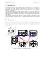
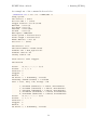
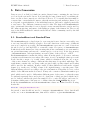
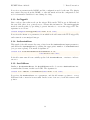
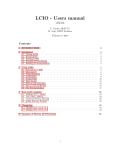
1.1. Architecture
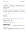
It is split into a number of different processes (see Figure 1), each communicating using
TCP sockets. A central Run Control provides an interface for controlling the whole DAQ
system; other processes connect to the Run Control to receive commands and to report
their status.
Key:
Application
Thread
Buffer
1
Data Collector
Signal
/data
Listening
Socket
Command
Cmd
Receiver
Data
Storage
Data
Merge
Data
Sender
M
Monitor
Cmd
Receiver
Data
Receiver
GUI
Logging
N
Producer
Data
Server
N
M
Data
Sender
Hardware
Polling
Cmd
Receiver
Log
Server
Cmd
Server
1
Hardware
Run Control
Cmd
Receiver
Log
Receiver
Cmd
Sender
GUI
Storage
Figure 1: Schematic of the DAQ architecture.
3
1
Logger
GUI
EUDET-Memo-2010-01
1. Introduction
Each piece of hardware that produces data (e.g. the TLU, the telescope, or a device
under test (DUT)) will have a Producer process. This will configure the hardware, read
out the data and send it to the Data Collector.
The Data Collector receives all the data streams from all the Producers, and combines
them into a single stream that is written to disk. It usually writes the data in a native
raw binary format, but it can be configured to write in other formats, such as LCIO.
The Logger receives log messages from all other processes, and displays them to the user,
as well as writing them all to file. This allows for easier debugging, since all log messages
are stored together in a central location.
A Monitor reads the data file and generates online-monitoring plots for display. In the
schematic it is shown to communicate with the DataCollector via a socket, but it actually
just reads the data file from disk (this may be changed in the future).
1.2. Directory Structure
The EUDAQ software is split into several parts that can each be compiled independently,
and are kept in separate subdirectories. The general structure is outlined below:
• main contains the main EUDAQ library with the parts that are common to most of
the software, and several command-line programs that depend only on this library.
All definitions in the library should be inside the eudaq namespace. It is organised
into the following subdirectories:
– src contains the source code, with library files having the extension .cc, and
program source files having the extension .cxx,
– include contains the header files inside the eudaq subdirectory (to match the
namespace),
– tmp contains all temporary files generated during compilation (dependency
(.d) and object (.o) files).
• root contains the parts that depend on Root, such as the RootMonitor and some
command-line utilities.
– src, include and tmp subdirectories as in main.
• gui contains the graphical programs that are built with Qt, such as the RunControl
and LogCollector.
• tlu and eudrb contain the parts that depend on the TLU and EUDRB respectively.
• vme contains a wrapper for the VME driver for the EUDRB.
• depfet, fortis, taki. . . contain the code for third-party producers that have
been used with the telescope.
• extern stores external software that is not part of EUDAQ itself, but that is needed
by EUDAQ in some cases, such as the ZestSC1 driver for the TLU and the Tsi148
VME driver.
• ports contains ports of EUDAQ to other platforms, such as Microsoft Visual C++.
4
EUDET-Memo-2010-01
1. Introduction
• bin contains the binaries (executables and libraries) generated from the other
directories.
• conf contains configuration files for running the beam telescope.
• data and logs are directories for storing the data and log files generated while
running the DAQ.
• doc contains documentation, such as this manual.
Each directory containing code has its own src, include and tmp subdirectories, as well
as a local Makefile containing the rules for building that directory. Header files usually
have a .hh extension so that they can be automatically recognised as C++ (as opposed
to C), and source files have either .cc for parts of a library or .cxx for executables. The
Makefiles contain rules to automatically combine all .cc files into libraries and to build
all .cxx files into executables.
5
EUDET-Memo-2010-01
2. Installing EUDAQ
2. Installing EUDAQ
2.1. Prerequisites
EUDAQ has relatively few dependencies on other software, but some features do rely
on other packages. The libusb library is only needed to communicate over USB with a
TLU[3]. The VME driver is only needed for reading out EUDRBs[4] via VME with a
Motorola MVME6100 single board computer. The other dependencies are only needed
for running the DAQ, and not for the common library (for example if you only want to
perform data analysis, or write a custom Producer to run in the EUDET telescope, but
not run the whole DAQ yourself).
2.1.1. libusb
In order to communicate with a TLU, the libusb library is needed. Therefore, if you want
to compile the TLU subdirectory, you should make sure that libusb is properly installed.
On Mac OS X, this can be installed using fink or macports. If using macports you may
also need to install the libusb-compat package. On Linux it may already be installed,
otherwise you should use the built-in package manager (aptitude/apt-get/yum etc.) to
install it. Make sure to get the development version, which may be named libusb-devel
instead of simply libusb. On Windows, libusb is only needed if compiling with cygwin,
in which case you should use the cygwin installer to install libusb. Otherwise libusb is
not needed, as the included ZestSC1 libraries should work as they are.
2.1.2. VME driver
In order to communicate with the EUDRB boards a VME library is needed. A kernel
module is included for the Tsi148 VME bridge, for use on a Motorola MVME6100, in
the extern/Tsi148 subdirectory. Installation of this module is beyond the scope of this
document.
The vme subdirectory includes code for accessing the VME bus with the Tsi148 module.
In principle other VME bridges could be used, you just need to write a C++ class that
inherits from the VMEInterface class and implements the necessary methods (look at
the TSI148Interface class for an example).
2.1.3. Qt
The graphical interface of EUDAQ uses the Qt graphical framework. In order to compile
the gui subdirectory, you must therefore have Qt installed. It is available in most Linux
distributions as the package qt4-devel, but make sure the version is at least 4.4, since
there are a few issues with earlier versions. If the included version is too old, or on other
platforms, it can be downloaded from http://qt.nokia.com/downloads. Select the
LGPL (free) version, then choose the complete development environment (it may also
work with just the framework, but this is untested). Make sure the QTDIR environment
6
EUDET-Memo-2010-01
2. Installing EUDAQ
variable is set to the Qt installation directory, and the $QTDIR/bin directory is in your
path.
If you are using Mac OS 10.6 (Snow Leopard) or later, it is recommended to use the
Cocoa version of Qt (as opposed to the Carbon version), since it supports 64-bit binaries,
and by default most other libraries are 64 bits on OS 10.6, so this should cause fewer
compilation issues. The Cocoa version is not so easy to find on the Qt website, at the
time of writing it could be found at http://qt.nokia.com/downloads/mac-os-cpp,
just cancel the download that starts, then find the link to the Cocoa (32 and 64-bit)
version.
2.1.4. Root
The online monitor, as well as a few command-line utilities (contained in the root
subdirectory), use the Root package for histogramming. It can be downloaded from
http://root.cern.ch. Make sure Root’s bin subdirectory is in your path, so that the
root-config utility can be run. This can be done by sourcing the thisroot.sh (or
thisroot.ch for csh-like shells) script in the bin directory of the Root installation:
source /path/to/root/bin/thisroot.sh
2.1.5. LCIO / EUTelescope
To enable the writing of LCIO files, or the conversion of native files to LCIO format,
eudaq must be linked against the LCIO and EUTelescope libraries. They are both
available from http://ilcsoft.desy.de. It is recommended to use the ilcinstall
script to install them and their dependencies.
The EUTELESCOPE and LCIO environment variables should be set to the installation
directories of EUTelescope and LCIO respectively. This can be done by sourcing the
build env.sh script as follows:
source /path/to/Eutelescope/HEAD/build_env.sh
2.2. Downloading
The EUDAQ source code is hosted on hepforge. The recommended way to obtain the
software is with subversion, since this will allow you to easily update to newer versions.
The latest version can be checked out with the following command:
svn co https://svn.hepforge.org/eudaq/trunk eudaq
This may fail if the installed version of subversion does not include ssl support. In this
case, replace the https with http. Occasionally, when connecting via http, it may fail
with an error resembling:
svn: REPORT of '/path...': 200 OK (http://svn.hepforge.org)
7
EUDET-Memo-2010-01
2. Installing EUDAQ
if this occurs, just repeat the command, it usually works the second time.
This will create the directory eudaq, and download the latest version into it. If you
already have a copy installed, and want to update it to the latest version, you do not need
to repeat the svn co command, just change to the eudaq directory use the command:
svn up
If you do not have subversion installed, and are unwilling or unable to install it, you can
download a zip file from http://projects.hepforge.org/eudaq/trac/browser/trunk,
at the bottom of the page is a link to download a zip file.
2.3. Configuring
Currently some manual editing is needed to configure the software. Hopefully this will
be replaced with a configuration script in the near future. In the main subdirectory you
should edit the file Makefile, and set USE LCIO, USE EUTELESCOPE and USE ROOT to 1 if
the corresponding packages are installed, or 0 if not. If they are enabled make sure that
the packages are correctly set up as described in section 2.1.4 and section 2.1.5.
2.4. Compiling
You should just have to run the command:
make
from the top eudaq directory to compile the common library, along with some commandline programs (the contents of the main subdirectory). If other parts are needed, you
can specify them as arguments to the make command. The different parts are:
main : The common library, and some command-line programs that depend on only this
library
tlu : The TLU library, and the command-line programs that depend on it.
gui : The graphical parts of the DAQ, such as the Run Control and Log Collector.
root : Parts of the software that depend on Root, in particular the Root Monitor.
vme : The VME library. This should only be compiled on an MVME6100 single-board
computer, as it is only compatible with the Tundra Tsi148 VME bridge, and PPC
processors.
eudrb : The code for accessing EUDRB boards over VME. Depends on the vme library,
and should only be compiled on an MVME6100 single-board computer.
The altro, altroUSB, depfet, fortis, mimoroma, mvd, pixelmanproducer, and taki
subdirectories are other producers for users of the EUDET telescope. They should not
be compiled unless specifically needed.
8
EUDET-Memo-2010-01
2. Installing EUDAQ
If any directory depends on another, it will be automatically built; there is no need to
specify it as well. For example, when you build the gui directory, the main directory
will automatically be built first.
9
EUDET-Memo-2010-01
3. Running EUDAQ
3. Running EUDAQ
This section will describe running the DAQ system, mainly from the point of view of
the EUDET JRA1 Pixel Telescope[5] with a DUT, although most of it should also be
applicable to the DAQ in general, even without the telescope.
All executable programs from the different subdirectories are placed inside the bin
subdirectory, and should be run from here.
They should all accept a -h (or --help) command-line parameter, which will provide a
summary of the different command-line options that can be used.
3.1. Preparation
Some preparation is needed to make sure the environment is set up correctly and the
necessary TCP ports are not blocked before the DAQ can run properly.
3.1.1. Directories
The DAQ expects two directories to exist, that it will use to store data files and log files.
They need not be real directories – they can be symbolic links to other directories if you
don’t want to store the files inside the EUDAQ installation.
First, inside the eudaq directory, there should be a directory (or symbolic link) called
data. This will contain the data files written by the Data Collector, as well as a file
containing the last run number, so that it will continue incrementing even when the DAQ
is restarted.
Secondly, there should be a directory (or symbolic link) called logs. This will be used
by the Log Collector to store log files containing all the log messages received.
3.1.2. Firewall
The different processes communicate between themselves using TCP/IP sockets. If a
firewall is running, it may block these connections, especially if the processes are running
on different computers. If all the processes will be run from the same computer, then
it is probably not necessary to do anything. If a port is blocked, you will see an error
message similar to the following when attempting to start some programs:
Are you sure the server is running? - Error 61 connecting to ←localhost:44000: Connection refused
The ports used may be configured on the command line, but the default values used are:
44000 : This is the port used to send commands from the Run Control.
44001 : This port is used to send data from the producers to the Data Collector.
44002 : This port is used to send log messages from all processes to the Log Collector.
10
EUDET-Memo-2010-01
3. Running EUDAQ
If processes will be run on different computers, then these ports should be opened up in
the firewall. The method for doing this depends on the Operating System used, and is
outside the scope of this manual.
3.1.3. Environment
When a process connects to the Run Control, it must be told what addresses to use
to connect to the Log Collector and (if it is a Producer) to the Data Collector. The
Run Control will ask the Log and Data Collectors what address to report, and these
processes therefore need a way to determine what address they are listening on. There
is no completely fool-proof way of determining this, so they look at the environment
variable $HOSTNAME.
Usually this should be the DNS name of the machine it is running on, but in some cases
it may not work correctly. If this is the case, it may be necessary to set this variable
manually, either to the real host name, or the machine’s IP address, or (if all the processes
will be run on the same computer) it can be set to localhost.
Depending on the command shell used, the command to do this should be either
“export HOSTNAME=name” (for bash-like shells) or “setenv HOSTNAME name” (for csh-like
shells), where name is the name to use.
3.1.4. TLU permissions
If you are not using a TLU, or not running on Linux, you may skip this part.
On Linux, the device file used to communicate over the USB bus is only accessible by the
user root. In order to get around this, there is a small program included (tlunoroot.exe)
that will locate this file and change its permissions. It is recommended that the owner
and permissions of this program be changed so that it can be run by any user, by running
the following commands as root, from the bin subdirectory:
chown root tlunoroot.exe
chmod u+s tlunoroot.exe
The tlunoroot.exe program can now be run by any user (not just root). It should
be run each time the machine is rebooted, or the TLU is plugged in. If you use the
STARTRUN script (section 3.3.1) this should happen automatically when you start the
DAQ.
It has been observed on some (Linux) machines, that even setting the permissions of the
USB device file is not enough, the TLU is still not accessible, resulting in an error like:
Uncaught exception:
No TLU detected
Please report this to the developers.
In this case the only workaround is to run the program (e.g. TLUControl.exe or
TLUProducer.exe) as root.
11
EUDET-Memo-2010-01
3. Running EUDAQ
3.2. Processes
The DAQ system is made up of a number of different processes that may all be run on
the same, or on different computers. They are each described below.
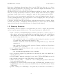
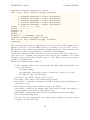
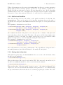
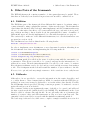
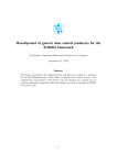
3.2.1. Run Control
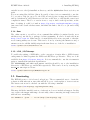
There are two versions of the Run Control – a text-based version, and a graphical version
(see Figure 2). The graphical version is preferred, since it is the most used, and therefore
the most tested and complete. The executable is called euRun.exe, or on Mac OS X
it is an application bundle called euRun.app. The text-based version can be useful for
testing, the executable is TestRunControl.exe.
Figure 2: The Run Control graphical user interface.
Normally no command-line options should be needed, but it can be told to listen on a
non-standard port, (e.g. to run two copies on the same machine), with the -a hporti
option:
./euRun.app/Contents/MacOS/euRun -a 3000
This example is for Mac OS X, where the executable is inside an application bundle,
on other architectures it will be just euRun.exe. Note also that it is not recommended
to run two copies of the DAQ simultaneously, since it becomes difficult to keep them
completely separate as the Log and Data Collectors must also be run on different ports.
12
EUDET-Memo-2010-01
3. Running EUDAQ
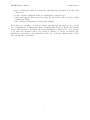
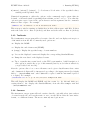
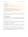
3.2.2. Log Collector
Running the Log Collector is optional. If it is run, then all log messages generated by all
other processes in the DAQ will be collected in one central location.
Figure 3: The Log Collector graphical user interface.
Like the Run Control, there are also two versions of the Log Collector. The graphical
version is called euLog.exe, or euLog.app on Mac OS X, and the text-based version is
called TestLogCollector.exe.
If it is being run on the same machine as the Run Control, it should not need any
command-line options. However, if it is run on a different machine, it must be told on
which machine the Run Control is running, using the -r hhostnamei option, e.g.:
./euLog.exe -r eudetmac001.cern.ch
It may also be told to listen on a non-standard port, using the -a hporti option, similar
to the Run Control.
3.2.3. Data Collector
The Data Collector is the process that collects all the raw data from the Producers,
merges all the incoming streams into a single data stream, and writes it to file.
Like the Log Collector, it should be told where to connect to the Run Control if it is not
running on the same machine, and it may also be told to listen on a non-standard port,
with the -r and -a options respectively, for example:
./TestDataCollector.exe -r eudet
3.2.4. TestProducer
For testing purposes, you may use the Test Producer. This works similarly to a real
producer, but does not talk to any real hardware, instead providing a menu for the user
to manually send events (or see the ExampleProducer, below).
13
EUDET-Memo-2010-01
3. Running EUDAQ
3.2.5. ExampleProducer
The ExampleProducer was written to illustrate the writing of a new Producer (see
section 4). However, it will actually generate some example data, and so can also be used
for testing purposes. It works more like a real Producer than the TestProducer, in that
it does not require user intervention to generate each trigger, and the data generated
emulates a simple (but realistic) sensor, and can be properly converted, and therefore
displayed in the Monitor.
3.2.6. TLUProducer
If you do not have a TLU in your setup, you may skip this part. Otherwise you should
run a TLUProducer, which will configure the TLU, and read out the timestamps and
send them to the Data Collector.
On the computer with the TLU connected, start the TLUProducer.exe program. If this
is not the same machine as the Run Control, use the -r option as for the Data and Log
Collectors. For example:
./TLUProducer.exe -r eudet.unige.ch:3000
If the TLUProducer fails to start, make sure the permissions are set up correctly (see
section 3.1.4).
3.2.7. EUDRBProducer
The EUDRB boards are used to read out the telescope sensors. The EUDRB Producer
is designed to run on a Motorola MVME6100 single board computer, using the Tundra
TSI148 VME bridge for communication with the EUDRBs.
If more than one EUDRBProducer is to be run, they must all have different names. The
name can be set with the -n hnamei option.
As with the other processes, the address of the Run Control should be set with the -r
option. An example is shown below:
./EUDRBProducer.exe -n EUDRB2 -r 192.168.1.1
3.2.8. Other Producer(s)
If you have a producer for your own hardware (see section 4), it should also have an
option to set the address of the Run Control.
3.2.9. RootMonitor
The RootMonitor reads the data file written by the Data Collector, and generates several
Root histograms that can be useful for online monitoring. Since it reads the native data
file directly, it must be run on the same machine as the Data Collector.
14
EUDET-Memo-2010-01
3. Running EUDAQ
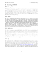
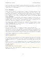
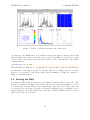
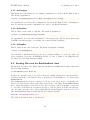
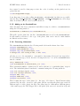
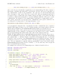
Figure 4: The Root Monitor configuration screen.
Although all plots are always generated internally by the Root Monitor, you can configure
which plots are displayed on screen. The Conf tab (see Figure 4) contains four groups:
Settings, where various parameters of the plots may be configured, Main Histograms
for selecting which plots to show on the Main tab, CDS Lego Plots to select whether
to show Lego plots of the per-board CDS profiles, and Board Displays to select which
plots to display on the per-board tabs. After making any changes the Apply button must
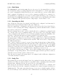
be pressed for them to take effect. Figure 5 shows an example of a per-board display
with 2D, x and y cluster profiles, cluster charge and number distributions, and a 2D
correlated double sampling (CDS) profile.
Due to the way the Root Monitor is implemented, it does not have access to the data
file at the time the histograms are booked. This is a problem, since depending on what
is in the data file, the number and parameters of the histograms may vary. To work
around this, a simple text configuration file is used to specify these parameters. It is
called rootmonitor.conf, and is located in the directory from which the RootMonitor
is run (usually bin). The file should contain one line per sensor in the data file, and may
also contain comments (lines starting with a # character). Each sensor line has a number
of parameters, separated by commas, and all apart from the first are optional. These
are: sensor type, width, height, pedestal file, seed threshold, neighbour threshold, cluster
threshold, cluster size. Where width and height are in pixels, and the thresholds are in
ADC units, and are used for clustering.
The RootMonitor can be run in one of two modes: online or offline. In online mode,
15
EUDET-Memo-2010-01
3. Running EUDAQ
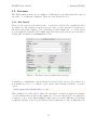
Figure 5: The Root Monitor showing some online plots.
it connects to the RunControl, so it will know when new runs are started, and it will
automatically open each new data file as it is created. In offline mode, there is no Run
Control, and it only analyses the data file it is given on the command line. An example
command line is:
./RootMonitor.exe -f 5432
This will run it in offline mode, opening the file corresponding to run 5432 (alternatively,
the full path to a file may be given). To run it in online mode, simply omit the -f option,
then the -r option may be used if the Run Control is running on a different computer or
using a non-standard port.
3.3. Running the DAQ
To start the DAQ, all the necessary processes must be started in the correct order. The
first process must be the Run Control, since all other processes will attempt to connect
to it when they start up. Then it is recommended to start the Log Collector, since any
log messages it receives may be useful to help with debugging in case everything does not
start as expected. Next, the Data Collector should be started. Finally all the Producers,
and if needed, the RootMonitor.
16
EUDET-Memo-2010-01
3. Running EUDAQ
3.3.1. STARTRUN
The STARTRUN file, in the main eudaq directory (as opposed to the bin subdirectory where
the executables exist), is a shell script that can be customized to load the appropriate
processes for running the DAQ. This allows you to start all the processes necessary with a
single command. If starting processes on other computers via SSH, it is recommended to
set up SSH keys so that the processes may be started without having to type a password.
In the future the STARTRUN script may be replaced with a more intelligent version that
uses a configuration file generated by the config script to decide what to load.
3.3.2. Controlling the DAQ
Once all the processes have been started, the DAQ can be configured, and runs may be
started and stopped using the Run Control (see Figure 2).
First the appropriate configuration should be selected from the drop-down list (see
section 3.3.3 for creating and editing configurations), and the GeoID should be verified
(see section 3.3.4), before continuing.
Then the Config button can be pressed, which will send a configuration command (with
the contents of the selected configuration file) to all connected processes. The full contents
of the configuration file will also be stored in the beginning-of-run-event (BORE) of the
data file, so that this information is always available along with the data.
Once all connected processes are fully configured, a run may be started, by pressing
the Start button. Whatever text is in the corresponding text box when the button is
pressed will be stored as a comment in the data file. This can be used to help identify
the different runs later.
Once a run is completed, it may be stopped by pressing the Stop button. Runs will also
stop and restart automatically when the data file reaches a threshold in size (by default
this is 1 GB). This is because there is a file size limit of 2 GB for storage on the GRID,
and the processed files can grow bigger than the original native files. The threshold size
for restarting a run may be configured in the config file (see section 3.3.3).
At any point a message may be sent to the log file by filling in the Log text box and
pressing the corresponding button. The text should appear in the LogCollector window,
and will be stored in the log file for later access.
Once the run is stopped, the system may be reconfigured with a different configuration,
or another run may be started.
3.3.3. Config Files
The Config drop-down in the Run Control is populated from the files in the config
subdirectory. These are just text files in a specific format, containing name-value pairs
separated into different sections. See section A.1 for an example file.
Any text from a # character until the end of the line is treated as a comment, and
ignored. Each section in the config file is delimited by a name in square brackets (e.g.
[RunControl]). The name represents the type of process to which it applies; if there
are several such processes, then they can be differentiated by including the name after
17
EUDET-Memo-2010-01
3. Running EUDAQ
a period (e.g. [Producer.Example]). Within each section, any number of parameters
may be specified, in the form Name = Value. It is then up to the individual processes
how these parameters are interpreted.
The entire contents of the config file will be sent to all processes during the configuration,
and each process will have the appropriate section selected. The file will also be attached
to the BORE, so that it is available with the data later, even if the original config file is
modified or deleted.
3.3.4. GeoID
The GeoID is a number representing the physical positioning of the telescope and DUT(s).
Each time a change is made to the telescope layout, this number should be incremented.
To change the number, double-click on it, and a window will appear with the new value.
By default it will increment the old value by one, so normally you should just click OK,
but if necessary you may edit the value first.
The GeoID is inserted into the config file when it is sent, so it is also stored in the data
file, and will be used to select the correct GEAR file for alignment during the data
analysis stage.
3.4. Other Utilities
There are a number of other utilities available that are not needed for running the DAQ,
but can be useful for other tasks such as debugging. The executables are all located in
the bin subdirectory. They should all accept a help (-h or --help) option, to print a
summary of the available options.
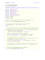
3.4.1. TLUControl
The TLUControl.exe program is a standalone program for running the TLU without
using the full DAQ. The most commonly used parameters are the following:
-d hmaski : The DUT mask; this defines which DUT connections are activated. It is a
bit-mask, so 1 means connector 0, 2 means connector 1 etc.
-a hmaski : The AND mask; this defines which external trigger inputs are activated. It
is a bit-mask, so 1 means channel 0, 2 means channel 1 etc. The specified channels
are ANDed together, and used to generate a trigger signal.
-t hmsecsi : Internal trigger period. If non-zero, the TLU will generate internal triggers
with the specified period in milliseconds.
-i hvaluesi : Input mode select. A sequence of comma-separated strings specifying
which connectors to use for the DUT inputs. Valid values are RJ45, LEMO, HDMI
and NONE.
-u : Pause the program after the TLU is configured, before starting triggers.
18
EUDET-Memo-2010-01
3. Running EUDAQ
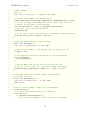
An example use of the command is shown below:
./TLUControl.exe -t 200 -d 3 -i LEMO,RJ45 -u
Using options:
TLU version = 0 (auto)
Bit file name = '' (auto)
Trigger interval = 200 ms (5 Hz)
DUT Mask = 0x03 (3)
Veto Mask = 0x00 (0)
And Mask = 0xff (255)
Or Mask
= 0x00 (0)
DUT inputs = LEMO,RJ45
Strobe period = 0x0003e8 (1000)
Strobe length = 0x000064 (100)
Enable DUT Veto = 0x00 (0)
Save file = '' (none)
TLU Version = v0.2c
TLU Serial number = 0x062b (1579)
Firmware file = TLU2_Toplevel.bit
Firmware version = 65
Library version = 65
Press enter to start triggers.
TLU Started!
Status:
20,00,--,--,--,-- (0,0)
Scalers:
0, 0, 0, 0
Particles: 2
Triggers: 0
Entries:
0
TS errors: 0, 0 (redundancy, re-read)
Timestamp: 0x8d768 (579432) = 0.00150891
Time: 0.009 s, Freq: 0 Hz, Average: 0 Hz
0,
1,
2,
3,
4,
0x27fb479 (41923705) = 0.109174, diff=41923705
0x7139ab9 (118725305) = 0.309174, diff=76801600
0xba780f9 (195526905) = 0.509174, diff=76801600
0x103b6739 (272328505) = 0.709174, diff=76801600
0x14cf4d79 (349130105) = 0.909174, diff=76801600
Status:
20,00,--,--,--,-- (0,1)
Scalers:
0, 0, 0, 0
Particles: 7
Triggers: 5
Entries:
5
TS errors: 0, 0 (redundancy, re-read)
19
EUDET-Memo-2010-01
3. Running EUDAQ
Timestamp: 0x1726fa48 (388430408) = 1.01152
Time: 1.023 s, Freq: 4.92913 Hz, Average: 4.88442 Hz
5,
6,
7,
8,
9,
0x196333b9 (425931705) = 1.10917, diff=76801600
0x1df719f9 (502733305) = 1.30917, diff=76801600
0x228b0039 (579534905) = 1.50917, diff=76801600
0x271ee679 (656336505) = 1.70917, diff=76801600
0x2bb2ccb9 (733138105) = 1.90917, diff=76801600
Status:
20,00,--,--,--,-- (0,1)
Scalers:
0, 0, 0, 0
Particles: 12
Triggers: 10
Entries:
5
TS errors: 0, 0 (redundancy, re-read)
Timestamp: 0x2e5bb708 (777762568) = 2.02538
Time: 2.037 s, Freq: 4.93259 Hz, Average: 4.90838 Hz
^CQuitting...
This sets up internal triggers at 5 Hz (200 ms period), and activates DUT inputs 0 and 1.
Input 0 is configured to use the LEMO connector, and input 1 to use the RJ45 connector.
The first part of the output just summarizes the input parameters. The next part shows
information about the version numbers of the TLU and the firmware.
It will then configure the TLU, and if the -u option is used, it will wait for the user to
press enter before continuing. The triggers are then enabled, and a summary of the status
is printed out periodically (by default every 1 second). The program can be stopped
cleanly by pressing Ctrl-C.
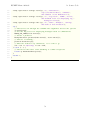
Each block of status output consists of:
• a list of triggers, if there were any since the last update (the first time there are
none), each showing:
– the trigger number,
– the timestamp of the trigger, in hex, decimal and converted to seconds,
– the difference since the last trigger.
• the status of the DUT connections (see below),
• the values of the scalers on the external trigger inputs,
• the number of “particles”, which means all the potential triggers (including those
that were vetoed),
• the number of triggers that actually got sent to the DUTs,
• the number of entries in the trigger buffer, this should be equal to the number of
triggers printed out at the top of the status block,
• the number of timestamp errors detected by redundancy, and by re-reading,
• the current timestamp value,
• the time since the run started, the current trigger frequency, and the average
frequency over the whole run.
20
EUDET-Memo-2010-01
3. Running EUDAQ
In the example output this block is repeated three times, before Ctrl-C is pressed to
stop it. The status is of the DUT connections formatted as:
• two digits for each DUT connection consisting of:
– two hyphens (--) if the connection is inactive, else
– the first digit represents the inputs from the DUT; with the busy line in bit
0 and the clock line in bit 1 (note the clock input can float low or high if a
LEMO input is selected, as it is not connected),
– the second digit represents the state of the FSM, as defined in the TLU
manual[3] (0 is ready, 1 is waiting for busy high, 4 is waiting for busy low, 5
is DUT-initiated veto, and F is an error condition).
• then in parentheses:
– the veto state (software veto in bit 0, overall veto in bit 1),
– the DMA state (1 when a DMA transfer is taking place).
3.4.2. VMETest
The VMETest.exe program uses the EUDAQ VME library to perform VME accesses. It
can be useful for determining whether a VME card is responding at a particular address.
The available options are:
-b haddressi : The base address for the VME accesses. This value will be added to the
offsets specified in the commands to give the actual address used.
-s hbytesi : Sets the window size in bytes. This is the amount of memory that is
mapped into the VME address space. Any accesses outside this range will result in
an access violation.
-a hbitsi : The address bus width in bits. Valid values are 16, 24, 32 or 64.
-d hbitsi : The data bus width in bits. Valid values are 8, 16, 32 or 64.
-m hmodei : The VME access mode. Valid values are S (single accesses), B (BLT), M
(MBLT), 2 (2eVME), E (2eSST) and T (2eSSTB).
The options set up the mode for the VME accesses. Following the options, a number of
commands can be specified to perform actual reads or writes. The commands can be any
of the following:
rhoffseti : Reads a value from the specified offset, and displays the value read.
Rhoffseti,hwordsi : Performs a block read of the specified number of words, starting
from the specified offset.
whoffseti,hvaluei : Writes the specified value to the specified offset.
21
EUDET-Memo-2010-01
3. Running EUDAQ
Whoffseti,hvalue1i[,hvalue2i...] : Performs a block write of the specified values,
starting at the specified offset.
Numerical arguments to either the options or the commands can be given either in
decimal, or in hexadecimal by prefixing them with 0x, as in C or C++. Note that the
options require a space between the option character and its argument, but the commands
must not have a space. For example:
./VMETest.exe -b 0x180000 -a 24 -d 16 w0x20,123 r0x10
This sets up a window starting at 180000 hex, in A24 address space with D16. It then
writes the value 123 to offset 32 (20 hex), and then reads the value at offset 16 (10 hex).
3.4.3. TestReader
The TestReader.exe program will read a native data file, and can display various pieces
of information from the file. Commonly used options are:
-b : Display the BORE.
-e : Display the end-of-run-event (EORE).
-d hrangei : Display the specified range of event numbers.
-p : Process the displayed events and display the corresponding StandardEvents.
-u : Dump the raw data for the displayed events.
-s : Try to resynchronize events based on the TLU event number. A full description of
this option is outside the scope of this manual (but if you don’t know what it is,
you probably don’t need it).
After the options a list of one or more filenames can be given. Any filenames that consist
only of numerical digits will be interpreted according to the input pattern (by default
this is “../data/run$6R.raw”, where $6R will be replaced with the run number padded
to 6 digits). For example:
./TestReader.exe -b -e -p -d 1-10,100,1000 example.raw 5432
This will display the BORE and EORE, and the events 1 to 10, 100 and 1000, processing them to also display the StandardEvents, from the files example.raw and
../data/run005432.raw.
3.4.4. Converter
The Converter.exe program will read a native data file, optionally select just a subset
of events from the file, and can then write it out to another file in either the same native
format, or a different format. The most commonly used options are:
22
EUDET-Memo-2010-01
3. Running EUDAQ
-t htypei : The file type to write out. The available types are listed below.
-e hrangei : Select the specified range of event numbers.
-s : Try to resynchronize events based on the TLU event number (see TestReader in
section 3.4.3).
The available output file types are as follows:
native : The native EUDAQ binary file format, consisting of a serialised stream of
DetectorEvents, containing the raw data read out from the hardware.
standard : Like the native format, this is also a serialised stream, but in this case
it contains StandardEvents, in which the raw data has been converted into a
standard format.
lcio : The standard LCIO file format used by the analysis software. This type is only
available if EUDAQ was compiled with LCIO support.
root : A Root file containing a TTree with the hit pixel information.
text : A simple text based format (not yet implemented).
mimoloop : A text based format mimicking the output of the mimoloop program (from
Angelo Cotta Ramusino and Lorenzo Chiarelli at INFN Ferrara).
Although this program can be used to convert a native data file into LCIO format, the
more usual (and therefore better tested) way is to use the EUTelescope converter.
3.4.5. ClusterExtractor
This program can be used to quickly extract some clusters from raw data. It is not as
sophisticated as the EUTelescope package, which should be preferred for real analysis,
but it can be useful for doing quick checks, possibly with the Correlator (see below). It
will read a native data file, perform a basic clustering, and then write these clusters to
one text file per sensor plane. The most commonly used options are:
-p hpixelsi : The cluster size in pixels. It should be an odd number, with 1 meaning
no clustering (just pixels over threshold), 3 meaning 3×3 pixel clusters, etc.
-n hadcsi : The noise level (sigma) in ADC units. This is used to scale the thresholds
in terms of the noise.
-s hthreshi : The threshold for seed pixels, in terms of the noise.
-c hthreshi : The threshold for the total charge of a cluster, in terms of the cumulative
noise of all the pixels in the cluster.
23
EUDET-Memo-2010-01
3. Running EUDAQ
-w : Reports the cluster centre as the weighted average of the pixels, instead of the
position of the seed pixel.
An example use is:
./ClusterExtractor.exe -p 3 -n 3.5 -s 6 -c 10 -w 5432
This will generate a number of text files named runNNN eutel M.txt, where NNN is the
run number, and M is the sensor plane number. The format of the output text files is as
follows:
2
182
241
3
111
5
113
7
252
95
2
153
120
1
67
1
141
2
240
170
51487659237
126
125
51489095892
346
51491334074
171
51495330212
305
189
The first line contains the event number, the number of clusters, and the TLU timestamp.
Then for each cluster there is one line, containing the x and y coordinates of the cluster
centre, and the total charge in ADC units. The cluster lines are prepended with a space
to make it easier to scan the file by eye.
3.4.6. Correlator
The Corellator.exe program is used to look for correlation between different sensor
planes. This can be a useful check that everything is properly aligned and synchronised.
It uses as input the text files generated by the ClusterExtractor program. It can
generate a number of plots that are saved to a Root file, and optionally displayed on
screen.
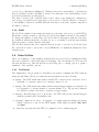
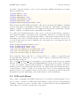
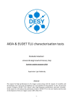
The basic correlation plot (Figure 6, top left) consists of looping over every pair of
clusters for each given event, and plotting the x (or y) coordinate of the first cluster
against that of the second. For clusters that come from the same track, these coordinates
should be correlated, giving a straight line on the 2D plot, while other pairs should be
uncorrelated, giving a more or less flat background. The amount of background depends
on the multiplicity of clusters; with only one cluster per event there is only one possible
pair, and no background. As the multiplicity increases, so will the background.
The Radon plot (Figure 6, top right) is a transformation of the basic plot, into a space
where each point represents a straight line in the original plot, with the x-axis representing
the angle, and the y-axis the offset from the centre. There should be a peak at the point
representing the correlation line of the first plot (see zoomed area).
Given the relative pitch of both sensors, the angle of the correlation line is known (e.g. it
will have a gradient of 1, or angle of 45◦ , if both sensors have the same pitch). Therefore
24
EUDET-Memo-2010-01
3. Running EUDAQ
Test Y Pos
!""#$!$
Test Y Pos
12000
10000
8000
6000
12000
10000
4000
!""#$"$
8000
6000
2000
4000
2000
0
-400
-300
-200
-100
0
100
200
300
400
-40
-20
0
20
40
60
80
Figure 6: Correlation plots.
there is no need to calculate the full Radon transform, but just a slice at the correct angle,
which is what is done in the third plot. We can see it gives a relatively flat background
level, with a very sharp peak at a particular offset that depends on the relative alignment
of the two sensors.
The most used parameters for running the program are:
-xN / -yN hpixelsi : Sets the width (x) or height(y) of the sensors, where N is 1 for
the first and 2 for the second sensor. The second sensor only needs to be specified
if it differs in dimension from the first. The sizes are needed since the text files do
not contain the sensor dimensions, and the dimensions are needed when booking
the histograms.
-pN hsizei : Sets the pitch of the two sensors. This is only needed for the 1D slice of
the Radon plot (-t option).
-l hclustersi : Limit to events with fewer than a certain number of clusters, in order
to reduce the background.
-r : Generate a Radon transform of the correlation plot.
-t : Generate a 1D slice of the radon transform at the angle corresponding to the ratio
of the pitches of the two sensors.
25
EUDET-Memo-2010-01
3. Running EUDAQ
-d : Display the generated plots on screen, as well as saving them to file.
An example usage is:
./Correlator.exe -x1 1152 -y1 576 -t -d run5432_eutel_1.txt run5432_eutel_2.txt
This sets the sensor dimensions to 1152×576 pixels, generates the 1D Radon slice (but
not the full Radon plot), using two text files generated by the ClusterExtractor as
input, and displays the generated plots on screen.
3.4.7. MagicLogBook
This program is designed to extract as much information as possible from data files and
log files, in order to reconstruct a log book. Despite its name, it is in fact not magical,
so it is preferable to keep a good log book during running, rather than relying on this
program to generate it later.
The available options are listed below:
-f hfieldsi : A list of fields to include in the output, in the form name=value, with
multiple fields separated by commas. If a predefined list is also specified these will
be appended to the list.
-s hseparatori : The separator to use between fields in the output. The default is a
tab character.
-h hstringi : A string that appears at the beginning of the header line (with the list of
field names), that can be used to differentiate it from the other lines. The default
is an empty string.
-p name : Use a predefined list of fields. Currently available values are normal and full.
-o hfilei : The output filename. By default the standard output is used.
The easiest method of running is to use a predefined list of fields. There are currently
two predefined lists available: normal and full. If neither of these are suitable, contact
the EUDAQ maintainer, as it may be possible to add more options.
The normal list includes:
•
•
•
•
the run number,
the config file name,
the run start time,
for the EUDRBs:
–
–
–
–
–
the mode,
the sensor type,
whether they are running unsynchronized,
the number of boards,
and the firmware version.
26
EUDET-Memo-2010-01
3. Running EUDAQ
• and for the TLU:
–
–
–
–
the internal trigger interval,
the AND mask,
the DUT mask,
and the firmware version.
The full list includes all the values from the normal list, plus the number of events in
the run and the end of run time. This is because these values can only be known by
reading the whole data file to the end, which is slow, especially for large data files.
If necessary, other information is available using custom fields, although the syntax for
these is a bit complicated, since it is designed to be as flexible as possible at specifying
any information in the data file. In the future it may be redefined in order to simplify it
if possible. Therefore it is recommended to use a predefined list of fields where possible.
Custom fields are specified as a comma separated list of items in the form name=value,
with the name being what will appear on the header line of the output, and the value
specifying what exactly to extract from the file. The possible values are illustrated below,
although not exhaustively:
events∗ : The number of events in the run.
config : The configuration name, or:
config:section:key : The value of the key from the corresponding section in
the config (e.g. config:Producer.EUDRB:NumBoards).
bore, tlu, eudrb, eore∗ : Something from the BORE, the TLUEvent or EUDRBEvent
subevents of the BORE, or the EORE, respectively:
bore:.Run : The run number
bore:hnamei : Otherwise, if the second part does not start with a period, the value
of the tag hnamei is used (e.g. tlu:DutMask or eudrb:MODE).
log : Something from the log file (not implemented yet).
∗
items marked with an asterisk require reading the whole data file, and are therefore
slow, especially when large data files are involved.
Note that the EUDRBEvent is now deprecated, having been replaced by the RawDataEvent,
but there is currently no way to specify this.
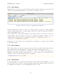
The MagicLogBook command is used as follows:
./MagicLogBook.exe -p normal ../data/*.raw
This will produce an output similar to the following:
Run
6371
6372
6373
6374
Config
Mode Det Start
U P Trg AND
eudet-beam
2009-07-29 07:44:39.535 1 6
0 0xf
eudet-beam
2009-07-29 08:03:05.079 1 6
0 0xf
eudet-m26test
2009-07-30 09:57:45.157 1 6 255 0xff
eudet-m26test
2009-07-30 10:00:45.205 1 6 255 0xff
27
DUT
0x10
0x10
0x12
0x12
Tfw Efw
241
241
241
241
EUDET-Memo-2010-01
6375 eudet-m26test
6376 eudet-m26test
6379 eudet-m26test
3. Running EUDAQ
2009-07-30 10:05:38.625 1 6
2009-07-30 10:10:00.107 1 6
2009-07-30 10:13:05.322 1 6
1 0xff 0x12 241
1 0xff 0x12 241
1 0xff 0x12 241
Note that the header row has been modified slightly to fit into the page width: the U
should be UnSync, P should be Planes, Trg should be TriggerInterval, Tfw should be
TLUfw, and Efw should be EUDRBfw. The columns Mode, Det and EUDRBfw are missing
from the output due to the fact that this information is now stored in a RawDataEvent,
which is not currently accessible with this version of the program.
3.4.8. Others
Some programs that are less used (or recently added) may not be described here. If they
look interesting, you can find out more about them by running them with the help (-h
or --help) option, or by examining the source code.
28
EUDET-Memo-2010-01
4. Writing a Producer
4. Writing a Producer
In order to integrate a DUT fully into the DAQ, it needs its own Producer. A Producer
is both a CommandReceiver and a DataSender, meaning it receives commands from
Run Control, and it also sends events to the Data Collector. A base class is provided
that users may inherit from, to make this as easy as possible. For example code, see
section A.2.
4.1. Configuration
The Configuration class is a way of storing configuration information in a way that
is easily accessible, and can be saved to or loaded from a human-readable file (see
section 3.3.3), and can be sent over the network. It is defined in the following header:
#include "eudaq/Configuration.hh"
The configuration consists of a number of sections, each of which contains a list of
name-value pairs. The values are stored as strings, but they can be converted to/from
arbitrary types. Methods are provided to load from or save to file, to set the current
section, and to set or get configuration values. An example use is shown below:
std::ifstream infile("../conf/ExampleConfig.conf");
eudaq::Configuration config(infile, "Producer.Example");
int param = config.Get("Parameter", 0);
std::cout << "Loaded config, param = " << param << std::endl;
config.Set("Parameter", param+1);
config.Set("OtherParam", "something");
std::ofstream outfile("Test.conf");
config.Save(outfile);
This creates a configuration loaded from the file ../conf/ExampleConfig.conf, selecting
the Producer.Example section. It then gets an integer parameter from the configuration
and displays it. Then it modifies the value of the parameter and sets another parameter,
before writing the configuration to the file Test.conf.
A configuration object will be received by the Producer during the configuration, as
described in section 4.2.1.
4.2. Receiving Commands
Whenever a command is received from the Run Control, a corresponding member function
of the Producer will be called by the code in the base classes. In order to react to a
command, the necessary code is simply put inside the corresponding method. The
Producer base class is declared by including the following header file:
#include "eudaq/Producer.hh"
29
EUDET-Memo-2010-01
4. Writing a Producer
4.2.1. OnConfigure
This method is called whenever a configure command is received from the Run Control.
The method signature is:
virtual void OnConfigure(const eudaq::Configuration & config);
As a parameter, it receives the configuration chosen in the Run Control. Information
may be extracted from the configuration in order to set up the hardware.
4.2.2. OnStartRun
This is called on the start of each run. The method signature is:
virtual void OnStartRun(unsigned param);
As a parameter, it receives the run number of the started run. The Producer must send
a BORE, and then prepare for reading out events from the hardware.
4.2.3. OnStopRun
This is called at the end of the run. The method signature is simply:
virtual void OnStopRun();
Care should be taken that there are no more events pending to be read out. Once all
data events have been sent, an EORE should also be sent, to signal to the DAQ that the
Producer has ended the run successfully.
4.3. Sending Data and the RawDataEvent class
Events may be sent to the DAQ using the Producer’s SendEvent() method that has
the following signature:
void SendEvent(const Event &);
It takes as a parameter an object derived from the eudaq::Event base class that will be
serialised and sent to the Data Collector. In practice it will usually be of concrete type
RawDataEvent.
The RawDataEvent is a generic container for blocks of raw bytes, used to encapsulate the
data read out from the sensor electronics and send it to the DAQ. Each RawDataEvent
may contain any number of raw data blocks. By convention each block usually corresponds
to one sensor, but this is not required; it is up to each Producer how the raw data are
encoded, since it is up to the corresponding DataConverterPlugin how they are decoded.
The RawDataEvent class is defined in the following header file:
#include "eudaq/RawDataEvent.hh"
The class is described in more detail below.
30
EUDET-Memo-2010-01
4. Writing a Producer
4.3.1. Constructing
A RawDataEvent is constructed as follows:
RawDataEvent event("EXAMPLE", run, event);
Where "EXAMPLE" is a string unique to the particular producer that will be used to
select the correct converter during decoding. The run and event parameters are the run
number and event number respectively.
As well as normal data events, the producer must also send a BORE and EORE at the
beginning and end of a run respectively. These are just normal RawDataEvent objects,
but with a particular flag set. The RawDataEvent has factory methods to simplify these
cases:
RawDataEvent::BORE("EXAMPLE", run);
RawDataEvent::EORE("EXAMPLE", run, event);
These methods return a RawDataEvent that may be either be sent directly to the DAQ,
or be modified first, e.g. by setting tags as described below in section 4.3.3.
4.3.2. Adding Data
Once a RawDataEvent has been constructed, data blocks may be added either using a
vector:
std::vector<unsigned char> buffer = ...;
event.AddBlock(id, buffer);
or using a pointer to a block of memory, and a length in bytes:
unsigned char * buffer = ...;
event.AddBlock(id, buffer, len);
Where id is an integer used to differentiate the different blocks. Usually it can just be 0
for the first block and increment by 1 for the following blocks. And buffer contains the
actual data for the block. If the buffer is a vector, the whole length is used, if it is a
pointer, then the length must be specified.
The type of the vector or pointer need not be unsigned char, since these methods are
in fact template methods that can take a vector of any basic type, but if larger types
are used, care must be taken about endianness, since the buffer will be converted to
unsigned char according to the endianness of the machine it is running on. Therefore
if the producer may run on different architectures steps should be taken to ensure that
any endianness issues are handled correctly.
4.3.3. Tags
The RawDataEvent (in fact any type that descends from the Event base class) may
also have tags set. These are name-value pairs containing extra information that does
not easily fit in the usual raw data. This is used particularly in the BORE to include
31
EUDET-Memo-2010-01
4. Writing a Producer
information about the particular run that may be useful for the decoding later. A tag
may be set as follows:
event.SetTag("Temperature", 42);
The value corresponding to the tag can be set as an arbitrary type (in this case an
integer), it will be converted to a string internally.
4.4. Log Messages
A method is provided for sending log messages to the central Log Collector. To use it
the follwing header should be included:
#include "eudaq/Logger.hh"
This defines the following macros for sending log messages, listed in decreasing order of
severity:
EUDAQ USER : A user-generated message (e.g. from the RunControl Log button).
EUDAQ ERROR : Something that has gone wrong and should probably be looked into.
EUDAQ WARN : A warning that something may not be quite right.
EUDAQ INFO : An message generated during normal running containing information that
may be useful to the user.
EUDAQ EXTRA : Some extra information that may be less useful in normal running.
EUDAQ DEBUG : Information for debugging purposes that will normally be hidden.
They are used as follows:
EUDAQ_ERROR("No keyboard detected: press F1 to continue.");
The messages will be sent to the central Log Collector if it is connected, otherwise they
will be displayed on the local terminal. The log level can be changed in the following
way:
EUDAQ_LOG_LEVEL("WARN");
Any messages lower than the specified level will just be ignored. This can be useful to
filter out unimportant messages and, for example, just display error messages.
32
EUDET-Memo-2010-01
5. Data Conversion
5. Data Conversion
Data are stored on disk, by default, in a native binary format, containing the raw data as
read out by the various Producers. It is basically the same format used for serialising the
data over the socket connection to the Data Collector. To be useful, this data must be
converted into a standardised format so that the monitoring and analysis software does
not depend on particularities of the individual sensors, but can be applied generically
to any sensor. Two different formats are used for this. The first is the StandardEvent
type, an internal class that does not depend on any external libraries, and is used by
the online monitoring, and many of the utility programs of the framework. The second
type is the LCIO standard format from the linear collider community, used by the full
analysis software.
5.1. StandardEvent and StandardPlane
The StandardEvent is a class designed to represent pixel sensor data in a reasonably easy
to use way, but still be flexible enough to store the data from a wide range of different
sensors as completely as possible. Each StandardEvent represents one event of data from
the whole telescope and any DUTs, so a run will consist of a sequence of StandardEvents.
It inherits from the Event base class, meaning that it has a run number, an event number,
an optional timestamp, and may also contain tags (see section 4.3.3). It also has an array
of StandardPlanes, each representing one sensor plane of the telescope or DUT.
Each StandardPlane contains the charge values from the pixels of one sensor, and may
contain several frames in cases where the sensor is read out multiple times per event.
It also has the concept of a “result” frame, which is calculated from the one or more
of the source frames according to different rules that may be specified with flags. The
result frame contains only one charge value per pixel, with a positive signal, and is what
will be used for the analysis. It may consist of either differences between the original
frames (e.g. in the case of CDS), a sum of all original frames, or specific parts of the
different frames selected according to the pivot information. Flags may be set to select
which of the different methods is used. It may also contain a submatrix number per
pixel, which can be used to differentiate different parts of the sensor, so that they may
be analyzed separately later, and a pivot boolean (true or false) per pixel, which can be
used to indicate whether the pixel was sampled before or after the trigger, and is used to
determine which parts of the sensor to combine when the FLAG NEEDCDS flag is set.
Both the StandardEvent and the StandardPlane classes are defined in the following
header file:
#include "eudaq/StandardEvent.hh"
In general, a user should not need to construct a StandardEvent object, but should
create one or more StandardPlanes, that will be added to a given StandardEvent.
33
EUDET-Memo-2010-01
5. Data Conversion
5.1.1. Constructor
The StandardPlane constructor has the following signature:
StandardPlane(unsigned id, const std::string & type,
const std::string & sensor = "");
Where id is an arbitrary numerical identifier for the plane that can be used to differentiate
between different planes of the same type, type is the type of the Producer that generated
the frame (should be the same as that in the Producer and the DataConverterPlugin),
and sensor is the name of the sensor, in the case that the Producer can read out more
than one type of sensor.
5.1.2. SetSizeRaw and SetSizeZS
Once a StandardPlane has been constructed, the size should be set. There are two
methods for doing this, depending on whether the data are stored in raw or zerosuppressed mode. In raw mode all pixels are stored, whether they have a signal or not.
In zero-suppressed mode, only those with a signal above a certain threshold are stored,
along with their coordinates, and any below the threshold are suppressed.
The signature of the SetSizeRaw method is:
void SetSizeRaw(unsigned w, unsigned h, unsigned frames = 1, int flags = 0);
Where w is the full width of the sensor (in the x-direction, usually columns) in pixels, h
is the full height of the sensor (in the y-direction, usually rows) in pixels, frames is the
number of frames, and flags may be a combination of the following values, separated
by a bitwise OR (i.e. |):
FLAG NEEDCDS : Indicates that the data are in 2 or 3 frames and that neighbouring frames
should be subtracted to produce the result.
FLAG NEGATIVE : Indicates that the charge values are negative, so should be negated to
produce the result.
FLAG ACCUMULATE : Indicates that all frames should be summed to produce the result.
FLAG WITHPIVOT : Indicates that pivot information is stored per pixel, and should be
used for constructing the result.
FLAG WITHSUBMAT : Indicates that submatrix information is stored per pixel.
FLAG DIFFCOORDS : Indicates that each frame can have different coordinates, in the case
of zero-suppressed data, otherwise all frames will share the same coordinates.
The signature of the SetSizeZS method is a follows:
void SetSizeZS(unsigned w, unsigned h, unsigned npix,
unsigned frames = 1, int flags = 0);
34
EUDET-Memo-2010-01
5. Data Conversion
Where all parameters are the same as in SetSizeRaw, but there is an extra parameter
(npix) that specifies how many pixels to preallocate. If the number of pixels above
threshold is known, this may be used to allocate them all at once. If not, then this
parameter may be set to zero, and pixels can be allocated as needed (but note that this
way may be slower, since memory will need to be reallocated for each new pixel).
5.1.3. SetPixel and PushPixel
Once the size has been set, the values of the pixels can then be loaded into the
StandardPlane. There are two methods for doing this: SetPixel, that sets the value of
an already allocated pixel, and PushPixel that allocates space for a new pixel and sets
that.
The signatures of SetPixel are as follows:
void SetPixel(unsigned index, unsigned x, unsigned y, unsigned pix,
bool pivot = false, unsigned frame = 0);
void SetPixel(unsigned index, unsigned x, unsigned y, unsigned pix,
unsigned frame);
where index is the index of the pixel to set, x and y are the coordinates of the pixel, and
pix is the charge value for the pixel. The value of the pivot, and the frame number may
optionally be set also, if relevant. Note that if only the pivot is set, care should be taken
that it is of type bool to avoid accidentally setting the frame instead.
The signatures of PushPixel are as follows:
void PushPixel(unsigned x, unsigned y, unsigned pix,
bool pivot = false, unsigned frame = 0);
void PushPixel(unsigned x, unsigned y, unsigned pix,
unsigned frame);
where all parameters are the same as in SetPixel. The only difference being the lack of
an index parameter, since this will always be the newly allocated pixel.
5.1.4. Setting other information
Other than the pixel values, the StandardPlane also stores some other information that
should be set if applicable:
void SetTLUEvent(unsigned ev);
This sets the trigger ID as read out from the TLU. If it was read out and stored, it
should be set using this method to allow cross checks in the analysis.
void SetPivotPixel(unsigned p);
This sets the value of the pivot pixel (or pivot row etc. – the value is arbitrary). It is
only here to allow cross-checks in the analysis; if the pixels are to be combined using
the pivot information, then it should also be set in the per-pixel pivot values. The value
35
EUDET-Memo-2010-01
5. Data Conversion
here cannot be used for that purpose since the order of reading out the pixels is not in
general known.
void SetFlags(FLAGS flags);
Some flags may be set after calling SetSizeRaw or SetSizeZS, but this is not possible
with the flags FLAG WITHPIVOT, FLAG WITHSUBMAT or FLAG DIFFCOORDS since these flags
affect how memory is allocated by those methods.
5.1.5. Adding to the StandardEvent
Once the plane has been constructed and filled, it may be added to a StandardPlane
using the following method:
StandardPlane & AddPlane(const StandardPlane &);
This will copy the plane into the list of StandardPlanes stored by the StandardEvent.
It will return a reference to the copy of the plane, that can be used to make further
modifications if necessary.
5.1.6. Extracting information
The StandardEvent inherits the following methods from the Event base class:
unsigned GetRunNumber() const;
unsigned GetEventNumber() const;
unsigned long long GetTimestamp() const;
T GetTag(const std::string & name, T def) const;
allowing access to the run number, event number, timestamp (if set) and any tags (where
T is an arbitrary type). It also has the following methods to access the StandardPlanes
that it contains:
size_t NumPlanes() const;
const StandardPlane & GetPlane(size_t i) const;
These return the number of planes stored, and a reference to a particular plane, respectively. The individual planes can then be examined using the following methods:
const std::string & Type() const;
const std::string & Sensor() const;
unsigned ID() const;
unsigned TLUEvent() const;
unsigned PivotPixel() const;
These return the type of the plane (i.e. the type of Producer / DataConverter that
generated it), the type of sensor for the plane (in the case that the plane type can hold
different types of sensor data), the ID of the plane (used to differentiate different planes
of the same type), the TLU trigger ID for the plane (if it was read out and stored) and
36
EUDET-Memo-2010-01
5. Data Conversion
the value of the pivot pixel (or pivot row) for the plane. Further information about the
plane is available in:
unsigned
unsigned
unsigned
unsigned
unsigned
unsigned
XSize() const;
YSize() const;
NumFrames() const;
TotalPixels() const;
HitPixels() const;
HitPixels(unsigned frame) const;
These return the full width and height of the sensor in pixels, the number of frames
stored for the plane, total number of pixels for the plane (i.e. full width × height), the
number of pixels over threshold (for zero-suppressed data) in the result frame, and the
number of pixels over threshold in a particular source frame.
Note that for the HitPixels method, there are two versions; the first takes no parameter
and returns the number of hit pixels in the result frame, while the second takes the frame
number as a parameter and returns the number of hit pixels in that frame from the
underlying source data. Normally the first version would be used, unless access is needed
to the raw data from the sensor. Similarly, the other methods for accessing the data all
have two versions:
double GetPixel(unsigned index) const;
double GetX(unsigned index) const;
double GetY(unsigned index) const;
const std::vector<pixel_t> & PixVector() const;
const std::vector<coord_t> & XVector() const;
const std::vector<coord_t> & YVector() const;
These return the charge value, the x coordinate and the y coordinate of a particular pixel
(for the first three methods), or a vector of these values for all pixels in the frame (for
the final three methods.
Here, coord t and pixel t are both double, even though the values stored are usually
integers. This is in order to make the StandardPlane as general as possible, allowing it
to store, for example, clusters with non-integer coordinates instead of pixels, and it also
makes it easier to pass the values directly into Root histograms without first having to
convert them to double. All the above methods also have a version taking the frame
number (as the second parameter if they already have one parameter), which returns the
information from the underlying source frame instead of the result frame.
5.2. LCIO and LCEvent
Due to time constraints, the LCIO format is not yet described in this manual. If you
need to write a converter to LCIO, first check whether a newer version of this manual is
available, otherwise you can look at the other converters that are already implemented,
and if that is not enough, seek the help of an expert.
37
EUDET-Memo-2010-01
5. Data Conversion
5.3. DataConverterPlugin
In order to allow different DUTs to easily incorporate their data into the monitoring
and analysis chain, the DataConverterPlugin system was developed. This allows all the
conversion code for each producer to be kept in one file, with the necessary parts being
called automatically as needed. This section describes how to write a new converter
plugin, to use existing converter plugins see section 6.3.
Writing a converter plugin for a new producer involves defining a new class that derives
from the DataConverterPlugin base class and implementing a few methods. Each
converter plugin contains a unique string that defines which type of RawDataEvents it
is able to convert. This is the same string that is set in the RawDataEvent when it is
created by the relevant producer. The DataConverterPlugin class is defined in the
following header:
#include "eudaq/DataConverterPlugin.hh"
The methods to be implemented are described below, and a full example is provided in
section A.3.
5.3.1. Constructor
The constructor should call the DataConverterPlugin constructor, and pass as a parameter the string representing the type of RawDataEvent this plugin can convert. A single
static instance of the converter should then be defined, and instantiated in the source
file. This is illustrated below:
class ExampleConverterPlugin : public eudaq::DataConverterPlugin {
ExampleConverterPlugin() : eudaq::DataConverterPlugin("EXAMPLE") {
// constructor...
}
// more methods...
static ExampleConverterPlugin m_instance;
};
ExampleConverterPlugin ExampleConverterPlugin::m_instance;
this will cause the constructor to be called during initialization of the program, and the
DataConverterPlugin constructor will automatically register the plugin and make it
available in the PluginManager.
5.3.2. Initialization
Every time a new run is started, the Initialize method will be called. It has the
following signature:
virtual void Initialize(const Event & ev, const Configuration & c);
38
EUDET-Memo-2010-01
5. Data Conversion
It receives as parameters the BORE, and the configuration used for the run. The plugin
may extract any tags from the BORE, or other information from the configuration, and
store it in member variables for use during decoding.
5.3.3. GetTriggerID
Since each producer that reads out the trigger ID from the TLU stores it differently in
the raw data, there is no general way to extract this information. The GetTriggerID
method remedies this, by providing a generic interface to access the trigger ID. The
signature is as follows:
virtual unsigned GetTriggerID(const Event & ev) const;
It receives the Event as a parameter, from which it should extract the TLU trigger ID,
and return it as an unsigned integer.
5.3.4. GetStandardEvent
This method should extract the sensor data from the RawDataEvent input parameter,
and fill in the StandardEvent by adding the appropriate number of StandardPlanes
(one per sensor plane). The method signature is:
virtual bool GetStandardSubEvent(StandardEvent & out,
const Event & in) const;
It should return true if it successfully updated the StandardEvent, or false to indicate
an error.
5.3.5. GetLCIOEvent
Similar to GetStandardEvent, the GetLCIOEvent method converts a RawDataEvent into
a standardized format, in this case LCIO. The signature is:
virtual lcio::LCEvent * GetLCIOEvent(const Event * ev) const;
It receives the RawDataEvent as a parameter, and should return a pointer to a new
LCEvent if the conversion is successful. In the event of an error, it should return a null
pointer.
39
EUDET-Memo-2010-01
6. Other Parts of the Framework
6. Other Parts of the Framework
The EUDAQ framework contains a number of other parts that may be useful. Those
that have not already been described in previous sections will be outlined below.
6.1. FileWriter
The FileWriter part of the framework allows different file formats to be written, using a
common interface, using a plugin-like system to define new file types. The FileWriter
class defines the interface that each type must implement, and the FileWriterFactory
allows code that writes data files to select any available file type, and write it in a generic
way, without needing to know details about the particular file format. A number of
different file types are already implemented, for a list with descriptions, see page 23
The easiest way to make use of the different FileWriters, is to use the Converter.exe
program (see section 3.4.4).
The FileWriter base class is defined in the following header:
#include "eudaq/FileWriter.hh"
In order to implement a new FileWriter, a new class must be written, inheriting from
the FileWriter base class, and implementing the following methods:
virtual void StartRun(unsigned);
virtual void WriteEvent(const DetectorEvent &);
virtual unsigned long long FileBytes() const;
The StartRun method is called at the start of each new run with the run number as
a parameter. This allows a new file to be opened, and any header information to be
written if necessary. Then the WriteEvent method is called for each event to be written.
Here the DetectorEvent can be decoded and processed and the necessary data written
to file. The FileBytes method should return the number of bytes written to the file.
However, it is optional, and may simply return zero if the actual size is not easily known.
6.2. FileReader
Although tools are provided to access the information in the native data files, and
to convert them to other formats (such as LCIO, for analysis with the EUTelescope
package), in some cases it may be preferable to access the native data directly. For this,
the FileReader class is provided, allowing a custom program to be written to access a
native file and process it as desired.
The constructor takes as an argument the name of the file to be opened, and will read
the first event from the file (which should be the BORE). The NextEvent() method can
then be called to advance through the file. It can optionally take as a parameter the
number of events to skip, and will return true as long as a new event was read. The
currently loaded event can be accessed with the GetDetectorEvent() method.
The basic usage is shown below, while a more complete example is available in section A.4:
40
EUDET-Memo-2010-01
6. Other Parts of the Framework
#include "eudaq/FileReader.hh"
#include <iostream>
int main(int argc, char ** argv) {
if (argc != 2) {
std::cerr << "usage: " << argv[0] << " file" << std::endl;
return 1;
}
eudaq::FileReader reader(argv[1]);
std::cout << "Opened file: " << reader.Filename() << std::endl;
std::cout << "BORE:\n" << reader.GetDetectorEvent() << std::endl;
while (reader.NextEvent()) {
std::cout << reader.GetDetectorEvent() << std::endl;
}
return 0;
}
This will open the file specified on the command line, and print out a summary of all the
events in there. Be aware that running it as it is may generate a large amount of output,
especially with large data files.
6.3. PluginManager
The PluginManager handles the different DataConverterPlugins, allowing raw data
stored in a RawDataEvent to be easily converted to a StandardEvent or LCEvent without
having to know the details of all the detector types in there. It is defined in the following
header:
#include "eudaq/PluginManager.hh"
In order to convert the events correctly, the plugins must have access to the information
in the BORE. Therefore, before any events may be converted, and for each data file, the
PluginManager must be initialized as follows:
eudaq::PluginManager::Initialize(bore);
The PluginManager will take care of passing the relevant parts of the BORE to the
appropriate DataConverterPlugins. The DetectorEvents can then be converted as
follows:
eudaq::StandardEvent sev = eudaq::PluginManager::ConvertToStandard(dev);
The PluginManager will take care of splitting the DetectorEvent into its constituent
subevents, and passing them all to the appropriate DataConverterPlugins to be inserted into the returned StandardEvent. For a slightly more complete example of the
PluginManager, see the ExampleReader in section A.4.
41
EUDET-Memo-2010-01
6. Other Parts of the Framework
6.4. OptionParser
The OptionParser is used to simplify parsing of command-line options. It provides a
way to specify which arguments a program accepts, with the types, default values and
descriptions, so that the help text can be automatically generated, and therefore is always
in sync with the code, and all command line programs can have a uniform interface.
All programs using the OptionParser will automatically provide a -h (and --help)
option to display the help text, as well as a -v (and --version) option to display the
program version, unless the program explicitly overrides these options with other ones
with the same names.
The OptionParser is the class that handles the actual parsing of the command line. The
signature of the constructor is as follows:
OptionParser(const std::string & name, const std::string & version,
const std::string & desc="", int minargs = -1, int maxargs = -1);
The first three arguments are the program name, version and (optionally) description,
and these are optionally followed by two numbers specifying the number of arguments
expected after the command line options. The default value of -1 for the minimum means
no arguments are allowed, and for the maximum means that an arbitrary number may
be given (i.e. there is no explicit maximum).
If the automatically generated help text is not sufficient, extra text may also be given to
display at the end of the help text, by passing it to the following method:
void OptionParser::ExtraHelpText(const std::string & text);
This can be used to provide extra information about the options to the program.
Once an OptionParser object has been constructed, the different options may be specified.
There are two types: OptionFlag, which specifies a simple option with no argument,
and the template Option<T>, which specifies an option taking an argument of type T.
The OptionFlag constructor has the following signature:
OptionFlag(OptionParser & op, const std::string & shortname,
const std::string & longname, const std::string & desc = "");
where op is a reference to the OptionParser object created previously, that will do the
actual parsing of the command line. It then takes two names: a short version (usually
a single character) that is used with a single hyphen, and a long version that must be
preceded by two hyphens on the command line. Finally, a description may be given that
will be displayed in the help text.
The Option constructor has the following two signatures, one for normal types, the other
for vectors of another type:
Option<T>(OptionParser & op, const std::string & shortname,
const std::string & longname, const T & deflt = T(),
const std::string & argname = "", const std::string & desc = "");
Option<std::vector<T> >(OptionParser & op, const std::string & shortname,
const std::string & longname, const std::string & argname = "",
42
EUDET-Memo-2010-01
6. Other Parts of the Framework
const std::string & sep = "", const std::string & desc = "");
where, in both cases, the first three arguments are as for OptionFlag. The first constructor
then takes a default value that will be used in the case the option is not specified on
the command line, a name for the argument to the option (to be used in the help text),
and a description of the option. The vector version also takes an argument name and a
description, but no default value (the default is always an empty vector), instead it takes
a separator, which is the string used to separate multiple elements of the vector on the
command line. By default (or if an empty string is specified), a comma will be used.
Once all the options have been specified, the command line can be parsed, which is done
by calling the following method of the OptionParser object:
OptionParser & OptionParser::Parse(const char ** args);
as an argument it takes the list of arguments from the command line (by convention
usually called argv). If there is an error during parsing, an exception may be thrown;
this should be handled by the HandleMainException method as described below.
Afterwards the values of the options can be accessed using their Value() method. The
IsSet() method is also available to tell whether an option has been set on the command
line (for OptionFlags this will hold the same value as the Value() method).
Finally, the OptionParser has a HandleMainException method that provides a way to
catch any unhandled exceptions, and either display help if it is a problem with parsing
the command line, or otherwise display a standard text informing the user of a problem.
It will also catch exceptions of type MessageException and display the message, without
treating it as an error, so this can be used to exit the program with a message to the
user. It is recommended to put the main program inside a try block, then call the
HandleMainException method from a catch(...) block, after any other exceptions
have been handled (if necessary).
An example use is shown below, illustrating most of what is described above:
1
2
3
4
5
6
7
8
9
10
11
12
13
14
15
16
#include "eudaq/OptionParser.hh"
#include "eudaq/Utils.hh"
#include <iostream>
int main(int /*argc*/, char ** argv) {
eudaq::OptionParser op("Example", "1.0", "An example program", 0);
eudaq::OptionFlag test(op, "t", "test", "Enable test");
eudaq::Option<double> example(op, "e", "example", 3.14, "value",
"Example parameter");
eudaq::Option<std::vector<int> > another(op, "a", "another", "values", ";",
"Example vector");
op.ExtraHelpText("Some more information about this");
try {
op.Parse(argv);
std::cout << "Test: " << (test.IsSet() ? "Enabled\n" : "Disabled\n")
<< "Example: " << example.Value() << "\n"
43
EUDET-Memo-2010-01
6. Other Parts of the Framework
17
<< "Another: " << eudaq::to_string(another.Value(), ", ")
18
<< std::endl;
19
if (op.NumArgs() == 0) {
20
throw(eudaq::MessageException("No arguments were given"));
21
}
22
for (unsigned i = 0; i < op.NumArgs(); ++i) {
23
std::cout << "Argument " << (i+1) << ": " << op.GetArg(i) << std::endl;
24
}
25
} catch(...) {
26
return op.HandleMainException();
27
}
28
return 0;
29 }
Running this program produces the following output:
./OptionExample.exe -h
Example version 1.0
An example program
usage: ./OptionExample.exe [options] [0 or more arguments]
options:
-t --test
Enable test
-e --example <value> (default = 42)
Example parameter
-a --another <values> (default = )
Example vector
Some more information about this program.
./OptionExample.exe
Test: Disabled
Example: 42
Another:
No arguments were given
./OptionExample.exe -t -e 2.718 -a 1;2;3 foo bar
Test: Enabled
Example: 2.718
Another: 1, 2, 3
Argument 1: foo
Argument 2: bar
44
EUDET-Memo-2010-01
6. Other Parts of the Framework
6.5. Timer
The Timer class wraps the underlying operating system’s timer functions, making them
easier to use in a platform independent way. Whenever a Timer object is created, it will
record the current time. Then at any time in the future, the elapsed time in seconds
may be accesses with the Seconds() method.
There is also a Stop() method to stop the timer counting, so any subsequent calls to
Seconds will return the same value, and a Restart() method to reset the timer’s start
time to the current time and start counting again. An example use is shown below:
#include "eudaq/Timer.hh"
Timer t;
function_a();
cout << "Function A took " << t.Seconds() << " seconds." << endl;
t.Restart();
function_b();
cout << "Function B took " << t.Seconds() << " seconds." << endl;
// wait 3 microseconds
t.Restart();
while (t.Seconds() < 3e-6) {
// do nothing
}
This shows a timer being used to measure the execution time of two functions, and to
wait for a small delay. Usually to wait for a delay, it is preferable to use sleep (or mSleep,
see section 6.6.4), but in most operating systems the minimum delay for a sleep is around
20 ms (even when using usleep which has microsecond resolution) so if the delay must
be shorter, a busy loop like above is needed.
6.6. Utils
The Utils package is a collection of useful functions and classes too small to merit their
own individual files. It is used by including the header:
#include "eudaq/Utils.hh"
Some of the most useful parts are described here.
6.6.1. to string
This is a template function that takes (almost) any type and returns the value converted
to a string. An optional second argument specifies the minimum number of digits to use
(padding with zeroes if necessary).
int value = 123;
strfunction(to_string(value));
strfunction(to_string(value, 6));
45
EUDET-Memo-2010-01
6. Other Parts of the Framework
This will pass first the string "123", and then the string "000123" to the function
strfunction.
6.6.2. from string
This template function is the inverse of to string. It takes as arguments a string and a
default value of type T, and returns an object of type T initialised from the string. If it
is not possible to convert the string to the required type, the default value is returned
instead.
std::string value = "456";
intfunction(from_string(value, 0));
This will call intfunction with the integer value 456.
6.6.3. hexdec
This is a class to facilitate printing numbers in both hexadecimal and decimal. It is
used similarly to to string, but when printed, it will display the value in hexadecimal,
followed by the value in decimal in parentheses. The hexadecimal values will be padded
to the full width of the type, unless a second argument is given specifying the minimum
number of hex digits to display.
short value = 789;
cout << hexdec(value) << endl
<< hexdec(value, 0) << endl;
This will display:
0x0315 (789)
0x315 (789)
If the result is required in a string, instead of being printed, this can be achieved with
to_string(hexdec(value)).
6.6.4. mSleep
This is a wrapper around the operating system’s sleep/usleep (or equivalent) function.
It takes as an argument the number of milliseconds to sleep. The advantage of this
function is that it will work on Linux, Mac OS X and Windows, as it will automatically
call the correct underlying function.
46
EUDET-Memo-2010-01
7. Reporting Issues
7. Reporting Issues
The HepForge system, on which EUDAQ is hosted, provides a system for reporting
bugs and for requesting new features, based on the Trac project. It is accessible at the
following address: http://projects.hepforge.org/eudaq/trac/report.
Here you may submit new reports (you are required to register first to do this), or follow
the status of existing bugs and feature requests. This is recommended over (or at least, as
well as) sending an email to the developers, as it ensures a record of the issue is available,
and others may follow the progress.
47
EUDET-Memo-2010-01
A. Source Code
A. Source Code
This section contains example code to illustrate the concepts in the manual, when they
are too long to be included in the main section.
All files are also present in the EUDAQ distribution; so if possible those versions should be
used, since they may be more up to date than the manual.
A.1. Example Config File
Latest version available at:
http://projects.hepforge.org/eudaq/trac/browser/trunk/conf/ExampleConfig.conf
1
2
3
4
5
6
7
8
9
10
11
12
13
14
15
16
17
18
19
20
21
22
23
24
25
26
27
28
# This is an example config file, you can adapt it to your needs.
# All text following a # character is treated as comments
[RunControl]
RunSizeLimit = 1000000000
[Producer.Example]
Parameter = 123
[Producer.TLU]
AndMask = 0xf
OrMask = 0
VetoMask = 0
DutMask = 20
TriggerInterval = 0
TrigRollover = 0
[Producer.EUDRB]
Version = 3
Det = MIMOSA26
Mode = ZS2
Unsynchronized = 0
ResetBusy = 0
IDOffset = 0
NumBoards = 3
Board0.Slot = 3
Board1.Slot = 5
Board2.Slot = 7
48
EUDET-Memo-2010-01
A. Source Code
A.2. Example Producer
Latest version available at:
http://projects.hepforge.org/eudaq/trac/browser/trunk/main/src/ExampleProducer.cxx
1
2
3
4
5
6
7
8
9
10
11
12
13
14
15
16
17
18
19
20
21
22
23
24
25
26
27
28
29
30
31
32
33
34
35
36
37
38
39
40
41
42
#include
#include
#include
#include
#include
#include
#include
#include
#include
#include
"eudaq/Producer.hh"
"eudaq/Logger.hh"
"eudaq/RawDataEvent.hh"
"eudaq/Timer.hh"
"eudaq/Utils.hh"
"eudaq/OptionParser.hh"
"eudaq/ExampleHardware.hh"
<iostream>
<ostream>
<vector>
// A name to identify the raw data format of the events generated
// Modify this to something appropriate for your producer.
static const std::string EVENT_TYPE = "Example";
// Declare a new class that inherits from eudaq::Producer
class ExampleProducer : public eudaq::Producer {
public:
// The constructor must call the eudaq::Producer constructor with the name
// and the runcontrol connection string, and initialize any member variables.
ExampleProducer(const std::string & name, const std::string & runcontrol)
: eudaq::Producer(name, runcontrol),
m_run(0), m_ev(0), stopping(false), done(false) {}
// This gets called whenever the DAQ is configured
virtual void OnConfigure(const eudaq::Configuration & config) {
std::cout << "Configuring: " << config.Name() << std::endl;
// Do any configuration of the hardware here
// Configuration file values are accessible as config.Get(name, default)
m_exampleparam = config.Get("Parameter", 0);
std::cout << "Example Parameter = " << m_exampleparam << std::endl;
hardware.Setup(m_exampleparam);
// At the end, set the status that will be displayed in the Run Control.
SetStatus(eudaq::Status::LVL_OK, "Configured (" + config.Name() + ")");
}
// This gets called whenever a new run is started
// It receives the new run number as a parameter
virtual void OnStartRun(unsigned param) {
49
EUDET-Memo-2010-01
43
44
45
46
47
48
49
50
51
52
53
54
55
56
57
58
59
60
61
62
63
64
65
66
67
68
69
70
71
72
73
74
75
76
77
78
79
80
81
82
83
84
85
86
87
88
A. Source Code
m_run = param;
m_ev = 0;
std::cout << "Start Run: " << m_run << std::endl;
// It must send a BORE to the Data Collector
eudaq::RawDataEvent bore(eudaq::RawDataEvent::BORE(EVENT_TYPE, m_run));
// You can set tags on the BORE that will be saved in the data file
// and can be used later to help decoding
bore.SetTag("EXAMPLE", eudaq::to_string(m_exampleparam));
// Send the event to the Data Collector
SendEvent(bore);
// At the end, set the status that will be displayed in the Run Control.
SetStatus(eudaq::Status::LVL_OK, "Running");
}
// This gets called whenever a run is stopped
virtual void OnStopRun() {
std::cout << "Stopping Run" << std::endl;
// Set a flag to signal to the polling loop that the run is over
stopping = true;
// wait until all events have been read out from the hardware
while (stopping) {
eudaq::mSleep(20);
}
// Send an EORE after all the real events have been sent
// You can also set tags on it (as with the BORE) if necessary
SendEvent(eudaq::RawDataEvent::EORE("Test", m_run, ++m_ev));
}
// This gets called when the Run Control is terminating,
// we should also exit.
virtual void OnTerminate() {
std::cout << "Terminating..." << std::endl;
done = true;
}
// This is just an example, adapt it to your hardware
void ReadoutLoop() {
// Loop until Run Control tells us to terminate
while (!done) {
if (!hardware.EventsPending()) {
// No events are pending, so check if the run is stopping
50
EUDET-Memo-2010-01
89
90
91
92
93
94
95
96
97
98
99
100
101
102
103
104
105
106
107
108
109
110
111
112
113
114
115
116
117
118
119
120
121
122
123
124
125
126
127
128
129
130
131
132
133
134
A. Source Code
if (stopping) {
// if so, signal that there are no events left
stopping = false;
}
// Now sleep for a bit, to prevent chewing up all the CPU
eudaq::mSleep(20);
// Then restart the loop
continue;
}
// If we get here, there must be data to read out
// Create a RawDataEvent to contain the event data to be sent
eudaq::RawDataEvent ev(EVENT_TYPE, m_run, m_ev);
for (unsigned plane = 0; plane < hardware.NumSensors(); ++plane) {
// Read out a block of raw data from the hardware
std::vector<unsigned char> buffer = hardware.ReadSensor(plane);
// Each data block has an ID that is used for ordering the planes later
// If there are multiple sensors, they should be numbered incrementally
// Add the block of raw data to the event
ev.AddBlock(plane, buffer);
}
hardware.CompletedEvent();
// Send the event to the Data Collector
SendEvent(ev);
// Now increment the event number
m_ev++;
}
}
private:
// This is just a dummy class representing the hardware
// It here basically that the example code will compile
// but it also generates example raw data to help illustrate the decoder
eudaq::ExampleHardware hardware;
unsigned m_run, m_ev, m_exampleparam;
bool stopping, done;
};
// The main function that will create a Producer instance and run it
int main(int /*argc*/, const char ** argv) {
// You can use the OptionParser to get command-line arguments
// then they will automatically be described in the help (-h) option
eudaq::OptionParser op("EUDAQ Example Producer", "1.0",
"Just an example, modify it to suit your own needs");
51
EUDET-Memo-2010-01
135
136
137
138
139
140
141
142
143
144
145
146
147
148
149
150
151
152
153
154
155
156
157
158 }
A. Source Code
eudaq::Option<std::string> rctrl(op, "r", "runcontrol",
"tcp://localhost:44000", "address",
"The address of the RunControl.");
eudaq::Option<std::string> level(op, "l", "log-level", "NONE", "level",
"The minimum level for displaying log ←messages locally");
eudaq::Option<std::string> name (op, "n", "name", "Example", "string",
"The name of this Producer");
try {
// This will look through the command-line arguments and set the options
op.Parse(argv);
// Set the Log level for displaying messages based on command-line
EUDAQ_LOG_LEVEL(level.Value());
// Create a producer
ExampleProducer producer(name.Value(), rctrl.Value());
// And set it running...
producer.ReadoutLoop();
// When the readout loop terminates, it is time to go
std::cout << "Quitting" << std::endl;
} catch (...) {
// This does some basic error handling of common exceptions
return op.HandleMainException();
}
return 0;
52
EUDET-Memo-2010-01
A. Source Code
A.3. Example DataConverterPlugin
Latest version available at:
http://projects.hepforge.org/eudaq/trac/browser/trunk/main/src/ExampleConverterPlugin.cc
1
2
3
4
5
6
7
8
9
10
11
12
13
14
15
16
17
18
19
20
21
22
23
24
25
26
27
28
29
30
31
32
33
34
35
36
37
38
39
40
41
#include "eudaq/DataConverterPlugin.hh"
#include "eudaq/StandardEvent.hh"
#include "eudaq/Utils.hh"
// All LCIO-specific parts are put in conditional compilation blocks
// so that the other parts may still be used if LCIO is not available.
#if USE_LCIO
# include "IMPL/LCEventImpl.h"
# include "IMPL/TrackerRawDataImpl.h"
# include "IMPL/LCCollectionVec.h"
# include "lcio.h"
#endif
namespace eudaq {
// The event type for which this converter plugin will be registered
// Modify this to match your actual event type (from the Producer)
static const std::string EVENT_TYPE = "Example";
// Declare a new class that inherits from DataConverterPlugin
class ExampleConverterPlugin : public DataConverterPlugin {
public:
// This is called once at the beginning of each run.
// You may extract information from the BORE and/or configuration
// and store it in member variables to use during the decoding later.
virtual void Initialize(const Event & bore,
const Configuration & cnf) {
m_exampleparam = bore.GetTag("EXAMPLE", 0);
(void)cnf; // just to suppress a warning about unused parameter cnf
}
// This should return the trigger ID (as provided by the TLU)
// if it was read out, otherwise it can either return (unsigned)-1,
// or be left undefined as there is already a default version.
virtual unsigned GetTriggerID(const Event & ev) const {
static const unsigned TRIGGER_OFFSET = 8;
// Make sure the event is of class RawDataEvent
if (const RawDataEvent * rev = dynamic_cast<const RawDataEvent *> ←(&ev)) {
// This is just an example, modified it to suit your raw data format
53
EUDET-Memo-2010-01
42
43
44
45
46
A. Source Code
// Make sure we have at least one block of data, and it is large enough
if (rev->NumBlocks() > 0 &&
rev->GetBlock(0).size() >= (TRIGGER_OFFSET + sizeof(short))) {
// Read a little-endian unsigned short from offset TRIGGER_OFFSET
return getlittleendian<unsigned short> ←(&rev->GetBlock(0)[TRIGGER_OFFSET]);
}
47
48
}
49
// If we are unable to extract the Trigger ID, signal with (unsigned)-1
50
return (unsigned)-1;
51
}
52
53
// Here, the data from the RawDataEvent is extracted into a StandardEvent.
54
// The return value indicates whether the conversion was successful.
55
// Again, this is just an example, adapted it for the actual data layout.
56
virtual bool GetStandardSubEvent(StandardEvent & sev,
57
const Event & ev) const {
58
// If the event type is used for different sensors
59
// they can be differentiated here
60
std::string sensortype = "example";
61
// Create a StandardPlane representing one sensor plane
62
int id = 0;
63
StandardPlane plane(id, EVENT_TYPE, sensortype);
64
// Set the number of pixels
65
int width = 100, height = 50;
66
plane.SetSizeRaw(width, height);
67
// Set the trigger ID
68
plane.SetTLUEvent(GetTriggerID(ev));
69
// Add the plane to the StandardEvent
70
sev.AddPlane(plane);
71
// Indicate that data was successfully converted
72
return true;
73
}
74
75 #if USE_LCIO
76
// This is where the conversion to LCIO is done
77
virtual lcio::LCEvent * GetLCIOEvent(const Event * ev) const {
78
return 0;
79
}
80 #endif
81
82
private:
83
84
// The constructor can be private, only one static instance is created
85
// The DataConverterPlugin constructor must be passed the event type
86
// in order to register this converter for the corresponding conversions
54
EUDET-Memo-2010-01
87
88
89
90
91
92
93
94
95
96
97
98
99
100
101
102 }
A. Source Code
// Member variables should also be initialized to default values here.
ExampleConverterPlugin()
: DataConverterPlugin(EVENT_TYPE), m_exampleparam(0)
{}
// Information extracted in Initialize() can be stored here:
unsigned m_exampleparam;
// The single instance of this converter plugin
static ExampleConverterPlugin m_instance;
}; // class ExampleConverterPlugin
// Instantiate the converter plugin instance
ExampleConverterPlugin ExampleConverterPlugin::m_instance;
// namespace eudaq
55
EUDET-Memo-2010-01
A. Source Code
A.4. Example Reader
Latest version available at:
http://projects.hepforge.org/eudaq/trac/browser/trunk/main/src/ExampleReader.cxx
1
2
3
4
5
6
7
8
9
10
11
12
13
14
15
16
17
18
19
20
21
22
23
24
25
26
27
28
29
30
31
32
33
34
35
36
37
38
39
40
41
42
#include
#include
#include
#include
"eudaq/FileReader.hh"
"eudaq/PluginManager.hh"
"eudaq/OptionParser.hh"
<iostream>
static const std::string EVENT_TYPE = "Example";
int main(int /*argc*/, const char ** argv) {
// You can use the OptionParser to get command-line arguments
// then they will automatically be described in the help (-h) option
eudaq::OptionParser op("EUDAQ Example File Reader", "1.0",
"Just an example, modify it to suit your own needs",
1);
eudaq::OptionFlag doraw(op, "r", "raw", "Display raw data from events");
eudaq::OptionFlag docon(op, "c", "converted", "Display converted events");
try {
// This will look through the command-line arguments and set the options
op.Parse(argv);
// Loop over all filenames
for (size_t i = 0; i < op.NumArgs(); ++i) {
// Create a reader for this file
eudaq::FileReader reader(op.GetArg(i));
// Display the actual filename (argument could have been a run number)
std::cout << "Opened file: " << reader.Filename() << std::endl;
// The BORE is now accessible in reader.GetDetectorEvent()
if (docon.IsSet()) {
// The PluginManager should be initialized with the BORE
eudaq::PluginManager::Initialize(reader.GetDetectorEvent());
}
// Now loop over all events in the file
while (reader.NextEvent()) {
if (reader.GetDetectorEvent().IsEORE()) {
std::cout << "End of run detected" << std::endl;
// Don't try to process if it is an EORE
break;
}
56
EUDET-Memo-2010-01
43
44
45
46
47
48
A. Source Code
if (doraw.IsSet()) {
// Display summary of raw event
//std::cout << reader.GetDetectorEvent() << std::endl;
try {
// Look for a specific RawDataEvent, will throw an exception if ←not found
const eudaq::RawDataEvent & rev =
reader.GetDetectorEvent().GetRawSubEvent(EVENT_TYPE);
// Display summary of the Example RawDataEvent
std::cout << rev << std::endl;
} catch (const eudaq::Exception & e) {
std::cout << "No " << EVENT_TYPE << " subevent in event "
<< reader.GetDetectorEvent().GetEventNumber()
<< std::endl;
}
49
50
51
52
53
54
55
56
57
58
}
59
60
if (docon.IsSet()) {
61
// Convert the RawDataEvent into a StandardEvent
62
eudaq::StandardEvent sev =
63
eudaq::PluginManager::ConvertToStandard(reader.GetDetectorEvent());
64
65
// Display summary of converted event
66
std::cout << sev << std::endl;
67
}
68
}
69
}
70
71
} catch (...) {
72
// This does some basic error handling of common exceptions
73
return op.HandleMainException();
74
}
75
return 0;
76 }
57
EUDET-Memo-2010-01
Glossary
Glossary
BORE beginning-of-run-event, basically a run header.
CDS correlated double sampling, when two frames are acquired, one before and one
after the trigger, and then subtracted to get the actual signal.
DUT device under test.
EORE end-of-run-event, basically a run trailer.
EUDRB the EUDET data reduction board, a VME readout board for pixel sensors.
LCIO Linear Collider I/O, the file format used by the analysis software.
TLU trigger logic unit.
Acknowledgements
This work is supported by the Commission of the European Communities under the 6th
Framework Programme “Structuring the European Research Area,” contract number
RII3–026126.
References
[1] P. Roloff, “The EUDET high resolution pixel telescope”, Nucl. Instrum. Meth., A604,
(2009), 265–268.
[2] A. Bulgheroni, “EUTelescope, the JRA1 tracking and reconstruction software: a
status report”, EUDET-Memo-2008-48.
URL http://www.eudet.org/e26/e28/e615/e835/eudet-memo-2008-48.pdf
[3] D. G. Cussans, “Description of the JRA1 Trigger Logic Unit (TLU), v0.2c”, EUDETMemo-2009-04.
URL http://www.eudet.org/e26/e28/e42441/e57298/EUDET-MEMO-2009-04.pdf
[4] A. Cotta Ramusino, “The EUDET Data Reduction Board (EUDRB)”, EUDETMemo-2008-38.
URL http://www.eudet.org/e26/e28/e615/e814/eudet-memo-2008-38.pdf
[5] EUDET JRA1 Group, “EUDET Pixel Telescope Data Taking Manual - Updated
Version 2009”, EUDET-Memo-2009-03.
URL http://www.eudet.org/e26/e28/e42441/e67493/EUDET-MEMO-2009-03.pdf
58