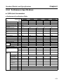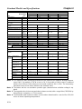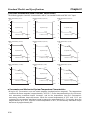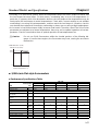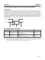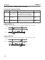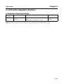
1
Chapter 4
Operation
●
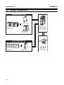
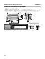
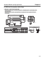
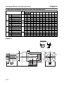
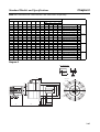
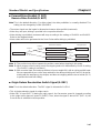
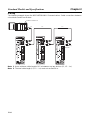
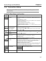
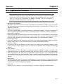
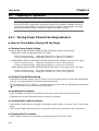
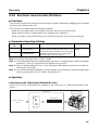
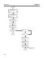
Checking the MECHATROLINK-II Connections
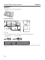
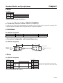
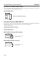
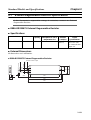
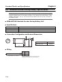
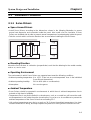
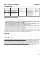
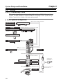
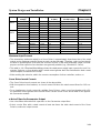
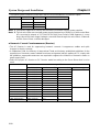
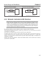
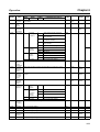
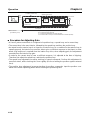
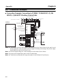
• The MECHATROLINK-II Connector must be securely connected to the MECHATROLINK-II Connector at the host controller.
• The MECHATROLINK-II Cable must be securely connected to the MECHATROLINK-II Connector
(CN6) at the Servo Driver.
• The termination resistance must be securely connected to the final Servo Driver.
■
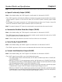
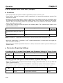
Turning ON Power
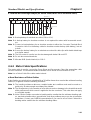
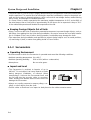
• First carry out the preliminary checks, and then turn ON the control-circuit power supply. It makes
no difference whether or not the main-circuit power supply is also turned ON.
• The ALM output will take approximately 2 seconds to turn ON after the power has been turned ON.
Do not attempt to detect an alarm using the Host Controller during this time (when power is being
supplied with the Host Controller connected).
■
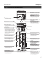
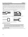
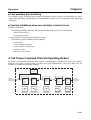
Checking Displays
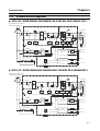
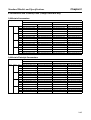
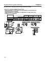
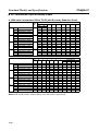
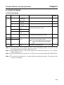
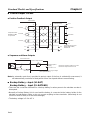
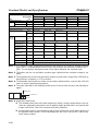
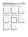
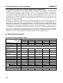
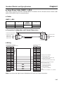
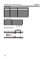
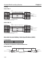
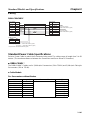
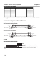
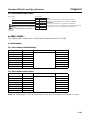
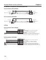
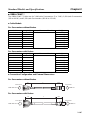
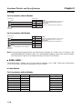
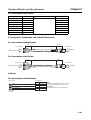
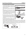
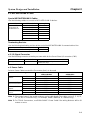
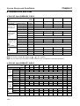
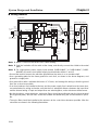
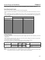
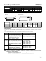
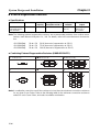
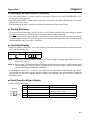
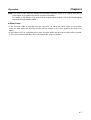
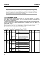
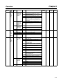
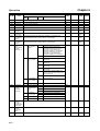
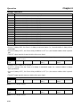
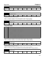
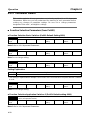
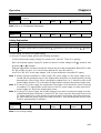
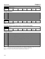
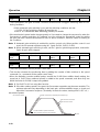
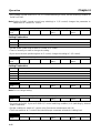
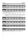
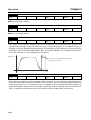
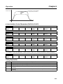
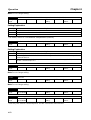
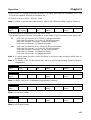
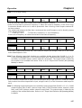
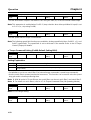
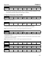
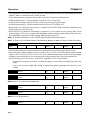
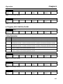
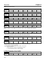
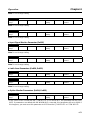
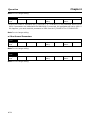
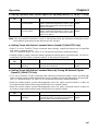
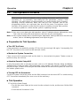
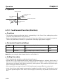
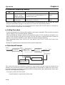
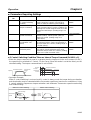
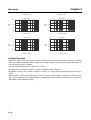
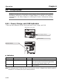
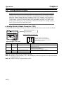
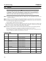
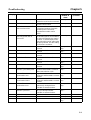
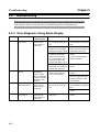
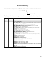
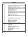
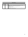
• When the power is turned ON, one of the codes shown below will be displayed at either the indicators or the Parameter Unit.
Normal
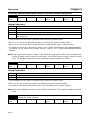
Error (Alarm Display)
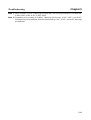
Note 1. The alarm code (the number shown in the alarm display) changes depending on the contents of the error.
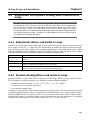
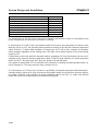
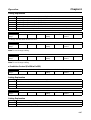
Note 2. When using a Servomotor with an absolute encoder for the first time, A.810 (backup error)
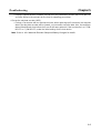
will be displayed. Clear this error by setting up the absolute encoder. (Refer to 4-2-2 Absolute Encoder Setup and Battery Changes).
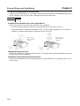
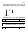
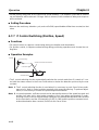
• If the display is normal (i.e., no errors), manually turn the Servomotor shaft forward and reverse,
and check to be sure that it agrees with the positive and negative on the speed display. Display the
speed feedback with the Computer Monitor Software and manually turn the Servomotor shaft forward and reverse.
■
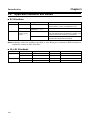
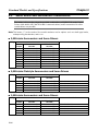
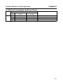
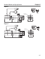
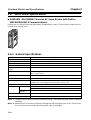
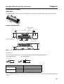
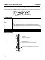
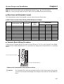
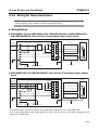
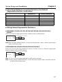
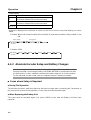
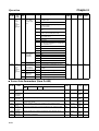
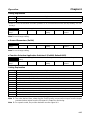
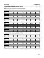
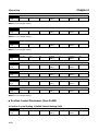
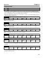
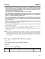
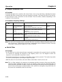
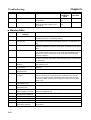
Panel Operator Status Display
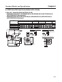
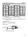
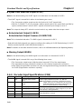
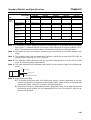
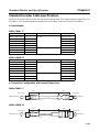
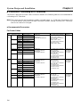
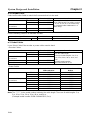
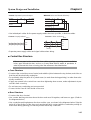
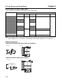
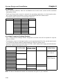
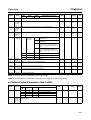
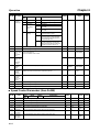
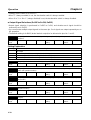
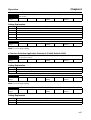
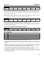
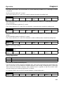
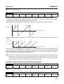
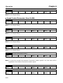
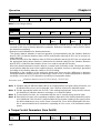
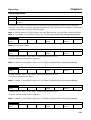
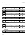
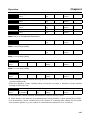
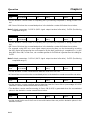
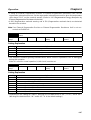
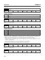
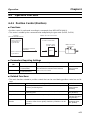
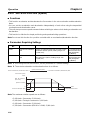
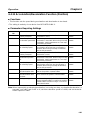
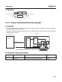
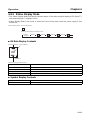
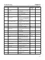
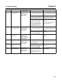
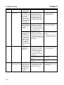
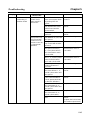
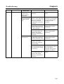
• Status Display (Bit Data)
Bit data
(1)
(2)
(3)
(4)
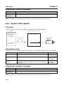
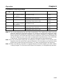
Item
(1)
(2)
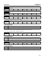
Bit data
Servomotor rotation detection
Servo ON/OFF
(3)
(4)
Command input detection
CONNECT
Display contents
Lit while Servomotor is rotating.
Lit when Servo is OFF.
Unlit when Servo is ON.
Lit while a command is being input.
Lit when CONNECT is complete.
4-5