1
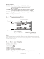
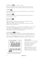
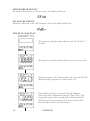
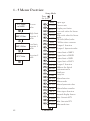
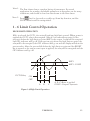
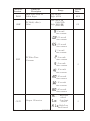
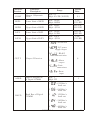
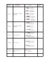
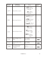
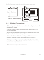
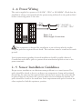
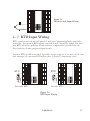
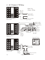
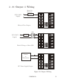
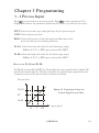
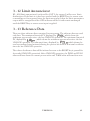
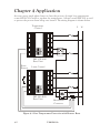
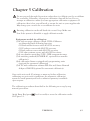
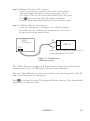
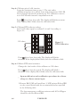
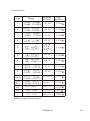
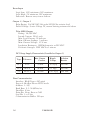
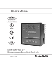
User's Manual
DIN EN ISO 9001
Certificate: 01 100 98505
R
LIMIT CONTROL ZEL L91
Microprocessor Based Limit Controller
UM0L911B
ZESTA ENGINEERING LTD.
Warning Symbol
The Symbol calls attention to an operating procedure, practice, or
the like, which, if not correctly performed or adhered to, could result
in personal injury or damage to or destruction of part or all of the
product and system. Do not proceed beyond a warning symbol
until the indicated conditions are fully understood and met.
Use the Manual
Installers
System Designer
Expert User
Read Chapter 1, 2
Read All Chapters
Read Page 12
NOTE:
It is strongly recommended that a process should incorporate a LIMIT CONTROL
like ZEL L91 which will shut down the equipment at a preset process condition in
order to preclude possible damage to products or system.
Information in this user's manual is subject to change without notice.
This manual is applicable for the products with software version 17 and later version.
Copyright October 2000, ZESTA ENGINEERING LTD, all rights reserved. No part
of this publication may be reproduced, transmitted, transcribed or stored in a
retrieval system, or translated into any language in any form by any means without
the written permission of ZESTA ENGINEERING LTD.
2
UM0L911B
Contents
Page No
Chapter 1 Overview
Page No
35
1-1 General
5
3-4 PV Shift
3-5 Digital Filter
1-2 Ordering Code
6
3-6 Process Alarms
36
1-3 Programming Port
7
37
1-4 Keys and Display
7
3-7 RS-485 Communication
3-8 Display Mode
1-5 Menu Overview
12
1-6 Limit Control Operation
13
1-7 Parameter Descriptions
16
Chapter 2 Installation
2-1 Unpacking
22
2-2 Mounting
22
2-3 Wiring Precautions
23
2-4 Power Wiring
25
2-5 Sensor Installation
Guidelines
25
2-6 Thermocouple Input
Wiring
26
2-7 RTD Input Wiring
27
2-8 Linear DC Input Wiring
28
2-9 Event Input Wiring
29
2-10 Output 1 Wiring
30
2-11 Output 2 Wiring
31
2-12 RS-485
32
3-9 Signal Conditioner DC
Power Supply
35
38
3-10 Remote Reset
38
40
3-11 Remote Lock
40
3-12 Limit Annunciator
41
3-13 Reference Data
41
Chapter 4 Applications
42
Chapter 5 Calibration
43
Chapter 6 Specifications
48
Chapter 7
Modbus Communications
52
Appendix
A-1 Error codes
61
Chapter 3 Programming
3-1 Process Input
33
3-2 Limit Control
34
3-3 Set point Range
34
UM0L911B
3
Figures & Tables
Page No
Figure 1-1 Programming Port Location
Figure 1-2 Front Panel Display
Figure 1-3 Power Up Sequence
Figure 1-4 High Limit Operation
Figure 1-5 Low Limit Operation
Figure 1-6 High/Low Limit Operation
Figure 2-1 Mounting Diagram
Figure 2-2 Lead Termination
Figure 2-3 Rear Terminal Connection Diagram
Figure 2-4 Power Supply Connections
Figure 2-5 Thermocouple Input Wiring
Figure 2-6 RTD Input Wiring
Figure 2-7 Linear Voltage Input Wiring
Figure 2-8 Linear Current Input Wiring
Figure 2-9 Event Input Wiring
Figure 2-10 Output 1 Wiring
Figure 2-11 Output 2 Wiring
Figure 2-12 RS-485 Wiring
Figure 3-1 Conversion Curve for Linear Type Process Value
Figure 3-2 Filter Characteristics
Figure 3-3 Normal Process Alarm
Figure 3-4 Latching Process Alarm
Figure 3-5 DC Power Supply Application
Figure 3-6 Remote Reset Application
Figure 3-7 Remote Lock Application
Figure 4-1 Over Temperature Protection with Remote Reset
Figure 5-1 Flow chart for Manual Calibration
Figure 5-2 Cold Junction Calibration Setup
Figure 5-3 RTD Calibration
7
8
10
13
14
15
23
24
24
25
27
27
28
28
29
30
31
32
33
35
37
37
39
40
40
42
44
45
46
Table 1-1 Display Form of Characters
Table 6-1 Input Characteristics
9
49
4
UM0L911B
Chapter 1 Overview
1 - 1 General
The limit control ZEL L91 is an over temperature protection or a high limit safety
device with a latching output, that removes power in an abnormal condition during the
process is higher than the high limit set point or lower than the low limit set point.
The unit is powered by 11-26 or 90-264 VDC/VAC supply, incorporating a 2 amp.
form C relay for limit control, an universal input which is fully programmable for
PT100, thermocouple types J, K, T, E, B, R, S, N, L and 0~60mV, an option port
available for one of the following functions: alarm output, RS-485 communication
interface, DC power supply output, limit annunciator output and event input.
Alternative output options include SSR drive and triac . The input signal is digitized by
using a 18-bit A to D converter. Its fast sampling rate (5 times/second) allows the L91 to
control fast process such as pressure and flow.
Digital communication RS-485 is available as an additional option. This option allows
ZEL L91 to be integrated with supervisory control system. An alarm output is another
option. A variety of alarm function and alarm mode can be programmed for a specific
application. The DC power supply output option is used for an external sensor or
transmitter. The event input option can be programmed for remote reset or remote
lock signal input. The limit annunciator option can be used to control an alarm buzzer.
Three kinds of method can be used to program ZEL L91. 1. use keys on front panel to
program the unit manually, 2. Use a PC and setup software to program the unit via
RS-485 port and 3. Use a pc and configuration software to program the unit via
programming port.
High accuracy, maximum flexibility, fast response and user friendly are the main
features of L91.
UM0L911B
5
1 - 2 Ordering Code
ZEL L91
1
Power Input
4: 90 - 264 VAC, 50/60 HZ
5: 11 - 26 VAC or VDC
9: Special Order
Signal Input
1: Standard Input
Thermocouple: J, K, T, E, B,
R, S, N, L
RTD: PT100 DIN, PT100 JIS
mV: 0~60 mV
2: Voltage: 0-1 V
3: Voltage : 0-10 V
4: Current: 0-20mA
9: Special Order
Example
Standard Model:
ZEL L91-4110
90 - 264 operating voltage
Input: Standard Input
Output 1: Relay
Option: None
3
2
Option
0: None
1: Form A Relay 2A/240VAC
2: Pulsed voltage to
drive SSR, 5V / 30mA
6: Triac Output, 1A / 240VAC, SSR
7: Isolated 20V / 25mA DC
Output Power Supply
8: Isolated 12V / 40 mA DC
Output Power Supply
9: Isolated 5V / 80mA DC
Output Power Supply
A: RS-485
B: Event input
C: Pulsed voltage to drive
SSR, 14V/40mA
H: Special order
Accessories
OM94-6 = Isolated 1A / 240VAC Triac Output Module ( SSR )
OM94-7 = 14V/40mA SSR Drive Module
DC94-1 = Isolated 20V / 25mA DC Output Power Supply
DC94-2 = Isolated 12V / 40mA DC Output Power Supply
DC94-3 = Isolated 5V / 80mA DC Output Power Supply
CM96-1 = Isolated RS-485 Interface Module
EI96-1 = Event Input Module
CC91-2 = Programming port cable for ZEL L91
UM0L911B = ZEL L91 User's Manual
6
4
Output 1
1: Form C relay rated
2A/240VAC
2: Pulsed voltage to
drive SSR, 5V/30mA
6: Triac Output
1A / 240VAC,SSR
C: Pulsed voltage to drive
SSR, 14V/40mA
9: Special order
UM0L911B
Related Products
SNA10A = Smart Network Adaptor for Third Party Software,
Converts 255 channels of RS-485 or RS-422 to
RS-232 Network
SNA10B = Smart Network Adaptor for ZEL-Net Software, Converts
255 channels of RS-485 or RS-422 to RS-232 Network
SNA12A = Smart Network Adaptor for programming port to RS-232
interface.
ZEL-Set = Configuration Software
1 - 3 Programming Port
Programming Port
pin 1
Control board
Power board
Open the housing
Top view of ZEL L91
Figure 1-1 Programming
Port Location
Note:
The programming port is used for off-line setup and calibration procedures only.
Don't attempt to make any connection to these jumpers when the unit is used for a
normal control purpose.
1 - 4 Keys and Display
KEYPAD OPERATION
SCROLL KEY
This key is used to:
1. Select a set point to be displayed.
2. Select a parameter to be viewed or adjusted.
3. Advance display from a parameter code to the next parameter code
UM0L911B
7
ENTER KEY
4 seconds, 8 seconds
Press the scroll key for 4 seconds the display will enter the setup
menu. Press this key for 8 seconds to enter the calibration mode.
UP KEY
This key is used to increase the selected parameter value during the
lock indicator is off.
DOWN KEY
This key is used to decrease the selected parameter value during
the lock indicator is off.
RESET KEY RESET
This key is used to:
1.Reset the limit condition after the process is within the limit.
2.Revert the display to the normal display.
3.Reset the latching alarm, once the alarm condition is removed.
4.Reset the limit annunciator.
Note: If the RESET key is left pressed, only ONE reset operation will
occur. If the unit subsequently goes into a state where reset is
required again, the RESET key (or remote reset contacts) must be
released (opened) and pressed (closed) again.
UNLOCK KEY RESET 4 seconds
Press the RESET key for 4 seconds to enable up/down key function,
also to reset the reference data (Section 3-13) and the lock indicator
will be extinguished. However, this function is disabled when remote
lock is selected for EIFN (Event input function). See section 3-11.
INDICATORS
Op1: Output 1 status indicator
OP2: Output 2 status indicator
LC: Degree C indicator
LF: Degree F indicator
PV: Process value
HSP1: High limit set point 1
LSP1: Low limit set point 1
SP2: Set point 2 for output 2
LOCK: Lock status indicator
Figure 1-2 Front Panel Display
8
UM0L911A
DISPLAY FORM
Table 1-1 Display Form of Characters
A
B
C
c
D
E
F
G
H
h
I
J
K
L
M
N
O
P
Q
R
S
T
U
V
W
X
Y
Z
?
=
: These characters are displayed differently.
How to display a 5-digit number:
For a number with decimal point the display will be shifted one digit right:
-199.99 will be displayed as -199.9, 4553.6 will be displayed as 4553
For a number without decimal point the display will be divided into two
alternating phases:
-19999 will be displayed as:
-45536 will be displayed as:
-9999 will be displayed as:
NORMAL DISPLAY
During normal operation, the unit can be configured to display the
process value, high limit or low limit set point ( HSP1 or LSP1
dependent on OUT1 selection ) or the word SAFE.
ABNORMAL DISPLAY
Whenever the process is outside the normal range, the process value
will be displayed.
UM0L911A
9
SENSOR BREAK DISPLAY
If a break is detected in the sensor circuit, the display will show:
A-D FAILURE DISPLAY
If failure is detected in the A-D converter circuit, the display will show:
POWER UP SEQUENCE
All segments of display and indicators are left off for 0.5
second.
All segments of display and indicators are lit for 1 second.
Display program code of the product for 1 second. The left
diagram shows program no.2 with version 17.
Display Date Code for 1 second. The left diagram
shows Year 2001, Month February (2), Date 25'th. This
means that the product is produced on February 25'th,
2001. Note that the month code A is for October, B is
for November and C is for December.
10
UM0L911B
Display the serial number ( 001~999 ) for 1 second.
Display the hours used for 2 seconds. The left
diagram shows that the unit has been used for
23456.7 hours since production.
Figure 1-3 Power Up Sequence
Verify all electrical connections have been properly made before applying power to
the unit. During power up, a self-test procedure is performed within 6.5 seconds.
During self-test period all outputs are left off. When the self-test procedure is
complete, the unit reverts to normal operation.
UM0L911A
11
1 - 5 Menu Overview
Setup Mode
Press
for 4 sec.
PV Value
or SAFE
INPT
Process
value
HSP1 Value
High limit
setpoint 1
value
LSP1 Value
Low limit
setpoint 1
value
Input type
UNIT Process unit
RESO Display resolution
Low scale value for linear
IN.LO
input
IN.HI High scale value for linear
input
SHIF PV shift (offset) value
FILT PV filter time constant
OUT1 Output 1 function
O1.HY Output 1 hysteresis value
HSP.L Lower limit of HSP1
SP2 Value
Set point 2
value
HSP.H Upper limit of HSP1
LSP.L
Lower limit of LSP1
LSP.H Upper limit of LSP1
OUT2 Output 2 function
ADDR Address for digital
communication
BAUD Baud rate
PARI Parity bit
AL.FN Alarm function
AL.MD Alarm mode
AL.HY Alarm hysteresis value
AL.FT Alarm failure transfer
EIFN
Event input function
DISP
Normal display format
PV.HI Max. historical PV
PV.LO Min. historical PV
T.ABN Abnormal time
12
UM0L911A
Note 1. The flow charts show a complete listing of parameters. For actual
application the number of available parameters is dependent on the setup
conditions, and should be less than that shown in the flow charts.
Note 2. Press RESET key for 4 seconds to enable up/down key function, and the
LOCK indicator will be extinguished.
1 - 6 Limit Control Operation
HIGH LIMIT OPERATION
If Hi. is selected for OUT1, the unit will perform high limit control. When power is
applied the OUT1 relay is de-energized. After 6.5 seconds self-test period, if the
process is below the high limit set point (HSP1), the output 1 relay will be energized
and OP1 indicator will go off. If the process goes above the high limit set point, the
relay will be de-energized, the OP1 indicator will go on and the display will show the
process value. After the process falls below the high limit set point and the RESET
key is pressed or the remote reset input is applied, the relay will be energized and the
OP1 indicator will go off.
PV
HSP1
HSP1 - O1.HY
OUT1 Relay
ON
OFF
A
B
C
A, B ,C=Reset is applied
O1.HY= Output1 hysteresis
Figure 1-4 High Limit Operation
UM0L911A
13
LOW LIMIT OPERATION
If Lo. is selected for OUT1, the unit will perform low limit control. When power is
applied the OUT1 relay is de-energized. After 6.5 seconds self-test period, if the
process is above the low limit set point (LSP1), the output 1 relay will be energized
and OP1 indicator will go off. If the process goes below the low limit set point, the
relay will be de-energized, the OP1 indicator will go on and the display will show the
process value. After the process rises above the low limit set point and the RESET
key is pressed or the remote reset input is applied, the relay will be energized and the
OP1 indicator will go off.
LSP1+O1.HY
LSP1
OUT1 Relay
ON
OFF
A
B
C
A, B ,C=Reset is applied
O1.HY= Output1 hysteresis
Figure 1-5 Low Limit Operation
14
UM0L911A
HIGH/LOW LIMIT OPERATION
If Hi.Lo is selected for OUT1, the unit will perform high/low limit control. When
power is applied the OUT1 relay is de-energized. After 6.5 seconds self-test period, if
the process is below the high limit set point (HSP1) and above the low limit set point
(LSP1), the output 1 relay will be energized and OP1 indicator will go off. If the
process goes above the high limit set point or below the low limit set point, the relay
will be de-energized, the OP1 indicator will go on and the display will show the
process value. After the process is within the normal operation range, and the
RESET key is pressed or the remote reset input is applied, the relay will be energized
and the OP1 indicator will go off.
A
BC
D
EF
HSP1
HSP1 - O1.HY
LSP + O1.HY
LSP1
OUT1 Relay
ON
OFF
A, B, C, D, E, F =Reset is applied
O1.HY= Output1 hysteresis
Figure 1-6 High/Low Limit Operation
UM0L911A
15
1 - 7 Parameter Descriptions
Parameter
Notation
Parameter
Description
HSP1
High Limit Set point 1
LSP1
Low Limit Set point 1
SP2
Set point 2 Value for
Output 2
INPT
16
Range
Low: HSP.L
High: HSP.H
Low: LSP.L
High: LSP.H
Low: -19999
High: 45536
0
: J type
thermocouple
1
: K type
thermocouple
2
: T type
thermocouple
3
: E type
thermocouple
4
: B type
thermocouple
5
: R type
thermocouple
6
: S type
thermocouple
7
: N type
thermocouple
8
: L type
thermocouple
9
: Pt100
ohms DIN curve
10
: PT100
ohms JIS curve
Input Type Selection
UM0L911B
Default
Value
100.0 ZE
(212.0 BF)
0 ZE
(32.0 BF)
90.0 ZE
(194.0 BF)
1
(0)
Parameter
Notation
INPT
Parameter
Description
Range
Input Type Selection
11
: 4~20
mA linear current
12
: 0~20
mA linear current
13
: 0~60
mV linear voltage
14
: 0~1 V
linear voltage
15
: 0~5 V
linear voltage
16
17
0
UNIT
RESO
IN.LO
Process Unit
Low Scale Value for
Linear Input
: 0~10V
linear voltage
:
Degree C unit
:
Degree F unit
2
:
Process unit
0
:
No decimal point
1
:
1 decimal point
2
:
2 decimal point
3
:
3 decimal point
Low: -19999
High: IN.HI
UM0L911A
1
(0)
: 1~5 V
linear voltage
1
Display Resolution
Default
Value
0
(1)
1
0
17
Parameter
Notation
IN.HI
SHIF
FILT
Parameter
Description
Range
High Scale Value for
Linear Input
Low: IN.LO
High: 45536
PV Shift ( offset )
Value
Low: -200.0 ZE
(-360.0 BF)
High: 200.0 ZE
(360.0 BF)
PV Filter Time
Constant
0
: 0 second
time constant
1
: 0.2 second
time constant
2
: 0.5 second
time constant
3
: 1 second
time constant
4
: 2 seconds
time constant
5
: 5 seconds
time constant
6
: 10 seconds
time constant
7
: 20 seconds
time constant
8
: 30 seconds
time constant
9
: 60 seconds
time constant
2
OUT1
Output 1 Function
3
4
18
UM0L911A
: High limit
control
: Low limit
control
: High/Low
limit control
Default
Value
100.0
0.0
2
2
Parameter
Notation
Parameter
Description
Range
Default
Value
O1.HY
Output 1 Hysteresis
Value
Low: 0.1
High: 10.0 ZE (18.0 BF)
HSP.L
Lower Limit of HSP1
Low: -19999
High: HSP.H
0 ZE
(32.0 BF)
HSP.H
Upper Limit of HSP1
Low: HSP.L
High: 45536
1000.0 ZE
(1832.0 BF)
LSP.L
Lower Limit of LSP1
Low: -19999
High: LSP.H
-100.0 ZE
(-148.0 BF)
LSP.H
Upper Limit of LSP1
Low: LSP.L
High: 45536
0 ZE
(32.0 BF)
OUT 2
ADDR
BAUD
Output 2 Function
Address Assignment
of Digital COMM
Baud Rate of Digital
COMM
0
: No function
1
:DC power
supply output
2
: RS-485
Communication
3
: Alarm
output
4
: Limit
annunciator
5
: Event
input
Low: 1
High: 255
0
: 0.3 Kbits/s
baud rate
1
: 0.6 Kbits/s
baud rate
2
: 1.2 Kbits/s
baud rate
3
: 2.4 Kbits/s
baud rate
4
: 4.8 Kbits/s
baud rate
UM0L911A
0.1
4
1
19
Parameter
Notation
BAUD
PARI
Parameter
Description
Range
Baud Rate of Digital
COMM
Parity Bit of Digital
COMM
AL.FN
Alarm function
AL.MD
Alarm mode
5
: 9.6 Kbits/s
baud rate
6
: 14.4 Kbits/s
baud rate
7
: 19.2 Kbits/s
baud rate
8
: 28.8 Kbits/s
baud rate
9
: 38.4 Kbits/s
baud rate
0
: 8 bit
even parity
1
: 8 bit
odd parity
2
: 8 bit
none parity
6
: Process
value high alarm
7
: Process
value low alarm
0
: Normal
alarm action
1
AL.HY
20
Alarm hysteresis
value
5
0
6
0
: Latching
alarm action
Low: 0.1
High: 10 ZE
(18.0 BF )
UM0L911A
Default
Value
0.1
Parameter
Notation
AL.FT
Parameter
Description
Range
Alarm failure transfer
0
: Alarm
output goes off
as unit fails
1
: Alarm
output goes on
as unit fails
0
1
EIFN
DISP
Event input function
: Remote
reset for output 1,
output 1 on.
: Remote
lock for the unit
0
: Display
process value
1
: Display
HSP1 or LSP1
value
2
0
0
: Display
the word
SAFE
PV.HI
Historical Max. value
of PV
Low: -19999
High: 45536
PV.LO
Historical Min. value
of PV
Low: -19999
High: 45536
T.ABN
Accumulated time
during abnormal
condition
Low: 0
High:6553.5 minutes
UM0L911A
1
: No event
function
2
Normal display format
Default
Value
21
Chapter 2 Installation
Dangerous voltages capable of causing death are sometimes present in this
instrument. Before installation or beginning any troubleshooting procedures the
power to all equipment must be switched off and isolated. Units suspected of
being faulty must be disconnected and removed to a properly equipped workshop
for testing and repair. Component replacement and internal adjustments must be
made by a qualified maintenance person only.
To minimize the possibility of fire or shock hazards, do not expose this
instrument to rain or excessive moisture.
Do not use this instrument in areas under hazardous conditions such
as excessive shock, vibration, dirt, moisture, corrosive gases or oil. The
ambient temperature of the areas should not exceed the maximum rating specified
in Chapter 6.
2 - 1 Unpacking
Upon receipt of the shipment remove the unit from the carton and inspect the unit
for shipping damage. If any damage due to transit , report and claim with the carrier.
Write down the model number, serial number, and date code for future reference
when corresponding with our service center. The serial number (S/N) and date code
(D/C) are labeled on the box and the housing of the unit.
2 - 2 Mounting
Make panel cutout to dimension shown in Figure 2-1.
22
UM0L911A
Install both mounting clamps and insert the housing into panel cutout.
_
45 +0.5
0
_
45 +0.5
0
Panel cutout
Figure 2-1 Mounting Diagram
Panel
86 mm
94 mm
2 - 3 Wiring Precautions
- Before wiring, verify the label for correct model number and options. Switch off
the power when checking.
- Care must be taken to ensure that maximum voltage rating specified on the
label are not exceeded.
- It is recommended that power of these units to be protected by fuses or circuit
breakers rated at the minimum value possible.
- All units should be installed inside a suitably grounded metal enclosure to
prevent live parts being accessible from human hands and metal tools.
- All wiring must conform to appropriate standards of good practice and local
codes and regulations. Wiring must be suitable for maximum voltage, current,
and temperature rating of the system.
- Take care not to over-tighten the terminal screws.
UM0L911A
23
- Unused control terminals should not be used as jumper points as they may be
internally connected, causing damage to the unit.
- Verify that the ratings of the output devices and the inputs as specified in
Chapter 6 are not exceeded.
- Electric power in industrial environments contains a certain amount of noise in
the form of transient voltage and spikes. This electrical noise can enter and
adversely affect the operation of microprocessor-based controls. For this reason
we strongly recommend the use of shielded thermocouple extension wire which
connects the sensor to the unit. This wire is a twisted-pair construction with foil
wrap and drain wire. The drain wire is to be attached to earth ground at the
sensor end only.
7.0mm max.
3.2mm min.
Figure 2-2 Lead Termination
3
PTA
B
4
V_
B _
5
6
N
7
NC
NO
C
2A
240 VAC
90-264VAC
47-63 Hz
10VA
8
OUT1
9
10
+
+
A
RTD
L
_
1
2
+
+
I
2A
240 VAC
_
OUT2
TX2
RS-485
or
Event Input TX1
CAT. I I
Figure 2-3 Rear Terminal
Connection Diagram
24
UM0L911A
2 - 4 Power Wiring
The unit is supplied to operate at 11-26 VAC / VDC or 90-264VAC. Check that the
installation voltage corresponds with the power rating indicated on the product label
before connecting power to the unit.
Fuse
1
6
2
7
3
8
4
9
5
10
90 ~ 264 VAC or
11 ~ 26 VAC / VDC
Figure 2-4
Power Supply Connections
This equipment is designed for installation in an enclosure which provides
adequate protection against electric shock. The enclosure must be connected to earth
ground.
Local requirements regarding electrical installation should be rigidly observed.
Consideration should be given to prevent from unauthorized person access to the
power terminals.
2 - 5 Sensor Installation Guidelines
Proper sensor installation can eliminate many problems in a control system. The
probe should be placed so that it can detect any temperature change with minimal
thermal lag. In a process that requires fairly constant heat output, the probe should
be placed closed to the heater. In a process where the heat demand is variable, the
probe should be closed to the work area. Some experiments with probe location are
often required to find this optimum position.
UM0L911A
25
In a liquid process, addition of a stirrer will help to eliminate thermal lag. Since the
thermocouple is basically a point measuring device, placing more than one
thermocouple in parallel will provide an average temperature readout and produce
better results in most air heated processes.
Proper sensor type is also a very important factor to obtain precise measurements.
The sensor must have the correct temperature range to meet the process
requirements. In special processes the sensor might need to have different
requirements such as leak-proof, anti-vibration, antiseptic, etc.
Standard thermocouple sensor limits of error are A4degrees F (A 2degrees C ) or
0.75% of sensed temperature (half that for special ) plus drift caused by improper
protection or an over-temperature occurrence. This error is far greater than controller
error and cannot be corrected at the sensor except by proper selection and
replacement.
2 - 6 Thermocouple Input Wiring
Thermocouple input connections are shown in Figure 2-5. The correct type of
thermocouple extension lead-wire or compensating cable must be used for the entire
distance between the unit and the thermocouple, ensuring that the correct polarity is
observed throughout. Joints in the cable should be avoided, if possible.
If the length of thermocouple plus the extension wire is too long, it may affect the
temperature measurement. A 400 ohms K type or a 500 ohms J type thermocouple
lead resistance will produce approximately 1 degree C temperature error .
26
UM0L911A
1
6
2
7
3
8
4
9
5
10
Figure 2.5
Thermocouple Input Wiring
2 - 7 RTD Input Wiring
RTD connection are shown in Figure 2-6, with the compensating lead connected to
terminal 4. For two-wire RTD inputs, terminals 4 and 5 should be linked. The threewire RTD offers the capability of lead resistance compensation provided that the
three leads are of same gauge and equal length.
Two-wire RTD should be avoided, if possible, for the purpose of accuracy. A 0.4 ohm
lead resistance of a two-wire RTD will produce 1 degree C temperature error.
RTD
1
6
2
7
3
8
4
5
Three-wire RTD
1
6
2
7
3
8
9
4
9
10
5
10
RTD
Two-wire RTD
Figure 2-6
RTD Input Wiring
UM0L911A
27
2 - 8 Linear DC Input Wiring
DC linear voltage and linear current connections are shown in Figure 2-7 and
Figure 2-8 .
6
2
7
3
8
4
9
5
10
+
0~60mV, 0~1V,
0~5V, 1~5V,
0~10V
1
Figure 2.7
Linear Voltage Input Wiring
0~20mA or
4~20mA
1
6
2
7
+
3
8
4
9
5
10
Figure 2.8
Linear Current Input Wiring
28
UM0L911A
2 - 9 Event Input wiring
1
6
1
6
2
7
2
7
3
8
3
8
4
9
4
9
5
10
5
10
Open Collector
Input
Switch Input
Figure 2-9
Event Input Wiring
The event input can accept a switch signal as well as an open collector signal. The
event input function (EIFN) is activated as the switch is closed or an open collector
(or a logic signal ) is pulled down.
UM0L911A
29
2 - 10 Output 1 Wiring
1
6
2
7
3
8
Max. 2A
Resistive
4
9
Load
5
10
Figure 2-10
Output 1 Wiring
120V/240V
Mains Supply
To Controller
Output
Relay or Triac Output
Direct Drive
120V /240V
Mains Supply
1
6
2
7
3
8
4
9
5
10
Relay or Triac (SSR)
Output to Drive
Contactor
Contactor
7
3
8
4
9
5
10 +
Load
+
30mA / 5V
Pulsed
Voltage
33
10 +
33
9
0V
SSR
_
+
2
5V
_
6
30
Three
Phase
Delta
Heater
Load
Three
Phase
Heater
Power
No Fuse
Breaker
Internal Circuit
1
Pulsed Voltage
to Drive SSR
To Controller
Output
UM0L911A
120V /240V
Mains Supply
To Controller
Output
2 - 11 Output 2 Wiring
Max. 2A
Resistive
LOAD
120V/240V
Supply
Relay or Triac Output
1
6
2
7
3
8
4
9
5
10
SSR
120V/240V
Supply
LOAD
+
Pulsed Voltage to Drive SSR
Sensor
or
Transmitter
+
DC Power Supply Output
1
6
2
7
3
8
4
9
5
10
1
6
2
7
3
8
4
9
5
10
Figure 2-11 Output 2 Wiring
UM0L911A
31
2 - 12 RS-485
Tx2
Tx1
1
6
2
7
3
8
4
9
5
10
RS-485 to RS-232
network adaptor
SNA10A or
SNA10B
RS-485
Twisted-Pair Wire
1
6
2
7
3
8
4
9
5
10
TX1
TX2
RS-232
Max. 247 units can be linked
Tx2 1
6
2
7
Tx1
Terminator
3
220 ohms/0.5W
32
8
4
9
5
10
UM0L911A
Figure 2-12
RS-485 Wiring
PC
Chapter 3 Programming
3 - 1 Process Input
Press
for 4 seconds to enter setup mode. Press
to select parameter. The
display will indicate the parameter symbol and the value ( or selection ) for that
INPT: Selects the sensor type and signal type for the process input.
UNIT: Selects the process unit.
RESO: Selects the location of the decimal point (Resolution) for
most (not all) process related parameters.
IN.LO: Selects the low scale value for the Linear type input
Hidden if: T/C or RTD type is selected for INPT
IN.HI: Selects the high scale value for the Linear type input
Hidden if: T/C or RTD type is selected for INPT
How to use IN.LO and IN.HI:
If 4-20mA is selected for INPT, let SL specifies the input signal low (ie. 4mA), SH
specifies the signal high (ie. 20mA), S specifies the current input signal value, the
conversion curve of the process value is shown as follows:
Process value
IN.LO
Figure 3-1 Conversion Curve for
Linear Type Process Value
PV
IN.HI
SL
S
SH
input signal
UM0L911A
33
S - SL
SH - SL
Example: a 4-20 mA current loop pressure transducer with range
0 - 15 kg/cm 2 is connected to input, then perform the
following setup:
Formula: PV = IN.LO + ( IN.HI - IN.LO )
INPT = 4-20 mA
UNIT = PU
RESO = 1-DP
IN.LO = 0.0
IN.HI = 15.0
Of course, you may select other value for RESO to alter
the resolution.
3 - 2 Limit Control
OUT1: Select the output 1 function. The available output 1 functions
are: High Limit Control, Low Limit Control and High/Low Limit
Control. Refer to Section 1-6 for the limit control operation.
O1.HY: Output 1 hysteresis value. The hysteresis value is adjusted to
a proper value to eliminate the relay jitter in a noisy
environment.
3 - 3 Set Point Range
HSP.L : Lower limit of HSP1
Hidden if LO is selected for OUT1
HSP.H : Upper limit of HSP1
Hidden if LO is selected for OUT1
LSP.L : Lower limit of LSP1
Hidden if HI is selected for OUT1
LSP.H : Upper limit of LSP1
Hidden if HI is selected for OUT1
HSP.L and HSP.H in setup menu are used to confine the adjustment
range of HSP1. LSP.L and LSP.H are used to confine the adjustment
range of LSP1.
34
UM0L911A
3 - 4 PV Shift
In certain application it is desirable to shift the indicated value from its actual value.
This can be easily accomplished with this unit by using the PV shift function.
Cycle the unit to the SHIF parameter by using the scroll key. The number you adjust
here, either positive or negative, will be added to the actual value. The SHIF function
will alter PV only.
SHIF: PV shift (offset) value
3 - 5 Digital Filter
In certain applications the process value is too unstable to be read. To Improve this a
programmable low pass filter incorporated in the ZEL L91 can be used. This is a first
order filter with time constant specified by FILT parameter which is contained in
setup menu. The FILT is defaulted to 0.5 sec. before shipping. Adjust FILT to change
the time constant from 0 to 60 seconds. 0 second represents no filter is applied to
the input signal. The filter is characterized by the following diagram.
PV
FILT=0
1sec
FILT=30
FILT=1
1sec
Time
Figure 3-2 Filter Characteristics
UM0L911A
35
3 - 6 Process Alarms
The output 2 will perform process alarm function by selecting ALM for OUT2 and
PV.H.A or PV.L.A for AL.FN. If PV.H.A is selected the alarm will perform process
high alarm. If PV.L.A is selected the alarm will perform process low alarm. The
process alarm sets an absolute trigger level. When the process exceeds that absolute
trigger level an alarm occurs. The trigger level is determined by SP2 (Set point 2
value) and AL.HY (Alarm hysteresis value). The hysteresis value is introduced to
avoid interference action of alarm in a noisy environment. Normally AL.HY can be
set with a minimum value(0.1).
Trigger levels for process high alarm are SP2 and SP2 AL.HY.
Trigger level for process low alarm are SP2+AL.HY and Sp2.
There are two types of alarm mode can be selected, these are: normal alarm and
latching alarm.
Normal Alarm: AL.MD= NORM
When a normal alarm is selected, the alarm output is de-energized in the non-alarm
condition and energized in an alarm condition.
Latching Alarm: AL.MD= LTCH
If a latching alarm is selected, once the alarm output is energized, it will remain
unchanged even if the alarm condition has been cleared unless the power is shut off
or the RESET key (or remote reset button) is pressed.
Failure Transfer: AL.FT = OFF or ON
In case of Sensor Break or A-D Failure occurs, the alarm output will be on or off
according to the selection of AL.FT.
Examples:
SP2 = 200
AL.MD = NORM
36
AL.HY = 10.0
AL.FN = PV.H.A
UM0L911A
Examples:
Figure 3.3
Normal Process Alarm
Process proceeds
200
200
190
190
SP2 = 200
AL.MD = LTCH
ON
200
200
190
190
200
OFF
190
AL.HY = 10.0
AL.FN = PV.H.A
Figure 3.4
Latching Process Alarm
Process proceeds
200
200
190
190
ON
200
200
200
190
190
190
3 - 7 RS-485 Communication
Using a PC for data communication is the most economic way. The signal is transmitted
and received through the PC communication Port (generally RS-232). Since a standard
PC can't support RS-485 port, a network adaptor (such as SNA10A, SNA10B) has to be
used to convert RS-485 to RS-232 for a PC if RS-485 is required for the data
communication. Many RS-485 units (up to 247 units) can be connected to one RS-232,
that is a PC with 4 comm ports can communicate with 988 units. It is quite economic.
UM0L911A
37
Select COMM for OUT2 in setup menu, the output 2 will perform
RS-485 interface with Modbus RTU Mode protocol.
Setup
1. Select COMM for OUT2
2. Set an unequal address (ADDR) for those units which are
connected to the same port.
3. Set the Baud Rate (BAUD) and Parity Bit (PARI) such that these
values are accordant with PC setup conditions.
3 - 8 Display Mode
The DISP in the setup menu is used to select the display format for the normal
condition. If PV is selected, the display will indicate the process value. If SP1 is
selected, the display will indicate HSP1 value for high limit control (OUT1= HI) and
high/low limit control (OUT1= HI.LO) or indicate LSP1 value for low limit
control(OUT1=LO). IF SAFE is selected, the display will indicate the word SAFE for
the normal condition.
However the display will indicate the process value if the process value goes beyond
high limit or low limit. If an error condition occurs, the display will indicate the error
symbol.
3 - 9 Signal Conditioner DC Power Supply
Three types of isolated DC power supply are available to supply an external
transmitter or sensor. These are 20V rated at 25mA, 12V rated at 40 mA and 5V
rated at 80 mA. The DC voltage is delivered to the output 2 terminals by selecting
DCPS for OUT2 in setup menu.
38
UM0L911A
Two-line
Transmitter
+
+
1
6
2
7
3
8
4
9
5
10
COM
1
6
IN
2
7
4-20mA
Set
OUT2 =
DC Power Supply
Figure 3-5
DC Power Supply
Application
Three-line
Transmitter
or sensor
+
OUT
+
V or mA
3
8
4
9
5
10
Bridge Type
Sensor
+
+
1
6
2
7
3
8
4
9
5
10
Caution:
Don't use the DC power supply beyond its rating current to avoid
damage. Purchase a correct voltage to suit your external devices. See
ordering code in section 1-2.
UM0L911A
39
3 - 10 Remote Reset
If EIFN is selected for OUT2 and REST is selected for EIFN, terminals 1 & 2 will act
as remote reset input. Pressing remote reset button will perform the same function as
pressing the RESET key. Refer to section 1-4 for RESET key function.
Remote
Reset
1
6
2
7
3
8
4
9
5
10
Setup
OUT2 = EIFN
EIFN = REST
Figure 3-6 Remote Reset
Application
3 - 11 Remote Lock
If EIFN is selected for OUT2 and LOCK is selected for EIFN, terminals 1 & 2 will
act as remote lock input. Turning the remote lock switch on will keep all the
parameter setting from been changed.
Remote
Lock
40
1
6
2
7
3
8
4
9
5
10
UM0L911A
Setup
OUT2 = EIFN
EIFN = LOCK
Figure 3-7 Remote Lock
Application
3 - 12 Limit Annunciator
If L_AN (Limit annunciator) is selected for OUT2, the output 2 will act as a Limit
Annunciator. If the limit is or has been reached and the RESET key (or remote reset
contacts)has not been pressed since the limit was reached, then the limit annunciator
output will be energized and the OP2 indicator will be lit and remain unchanged
until the RESET key or remote reset input is applied.
3 - 13 Reference Data
There are three reference data contained in setup menu. The reference data are read
only data. The maximum historical PV, displayed by
,which shows the
maximum process value since the last UNLOCK operation. The minimum historical
PV, displayed by
, which shows the minimum process value since the last
UNLOCK operation. The abnormal time, displayed by
,which shows the
total accumulated time (minutes) during the process has been in abnormal condition
since the last UNLOCK operation.
The values of reference data will be initiated as soon as the RESET key is pressed for
4 seconds (UNLOCK operation). After UNLOCK operation, the PV.HI and PV.LO
values will start from the current process value and T.ABN value will start from zero.
UM0L911A
41
Chapter 4 Application
An oven uses a single phase heater to heat the process. A single loop temperature
control ZEL C91 is used to regulate the temperature. A limit control ZEL L91 is used
to protect the process from being over heated. The wiring diagram is shown below.
Temperature
Control
L
1
6
2
7
3
8
4
9
5
10
ZEL C91-4120
Rear View
Reset
Button
Limit Control
1
6
2
7
3
8
4
9
5
10
Heater
ZEL L91-411B
Rear View
Mechanical
Contactor
Figure 4-1 Over Temperature Protection with Remote Reset
42
UM0L911A
N
Chapter 5 Calibration
Do not proceed through this section unless there is a definite need to re-calibrate
the controller. Otherwise, all previous calibration data will be lost. Do not
attempt re-calibration unless you have appropriate calibration equipment. If
calibration data is lost, you will need to return the unit to your supplier who
May change you a service fee to re-calibrate the unit.
Entering calibration mode will break the control loop. Make sure
that if the system is allowable to apply calibration mode.
Equipments needed for calibration:
(1) A high accuracy calibrator (Fluck 5520A Calibrator
recommended) with following function:
0-100mA millivolt source with A0.005% accuracy
0-10V voltage source with A0.005% accuracy
0-20mA current source with A0.005% accuracy
0-300 ohm resistant source with A0.005% accuracy
(2) A test chamber providing 25 ZE - 50ZE temperature range
(3) A switching network (SCANER 80, optional for automatic
calibration)
(4) A calibration fixture equipped with programming units
(optional for automatic calibration)
(5) A PC with calibration software ZEL-Net and Smart Network
Adaptor SNA10B (optional for automatic calibration)
Since each unit needs 30 minutes to warm up before calibration,
calibrating one unit each is inefficient. An automatic calibration
system for small quantity well as for unlimited quantity is available
upon request.
The calibration procedures described in the following are a step by step
manual procedures.
Apply Enter Key (press
See Figure 5-1.
for 8 seconds) to enter the calibration mode.
UM0L911A
43
Normal Mode
4 seconds
RESET
Figure 5-1
Flow Chart for Manual
Calibraton
Setup Mode
4 seconds
RESET
Step 1
Ad0
4 seconds
RESET
Step 2
ADG
4 seconds
RESET
Step 3
CJTL
4 seconds
RESET
Step 4
CJG
4 seconds
RESET
Step 5
REF
4 seconds
RESET
Step 6
SR
4 seconds
Step1: Calibrate Zero of A to D converter.
Short terminal 4 and 5, then press
for at least 4 seconds.
The display will blink a moment. If the display didn't blink,
then the calibration fails.
44
UM0L911A
Step 2: Calibrate Gain of A to D converter.
Send a span signal to terminal 4 and 5 with correct polarity.
The span signal is 60 mV for thermocouple input, 1V for
0-1V input, 10V for 0-10V input and 20mA for 0-20 mA input.
Press
for at least 4 seconds. The display will blink a
moment. If the display didn't blink, then the calibration fails.
Step 3: Calibrate offset of cold junction.
Setup the equipment according to the following diagram
for calibrating the cold junction compensation. Note that a
K type thermocouple must be used.
5520A
Calibrator
K-TC
K+
4
ZEL L91
5
KStay at least 20 minutes in still-air room
room temperature 25 A 3 LC
Figure 5-2 Cold Junction
Calibration Setup
The 5520A calibrator is configured as K type thermocouple output with internal
compensation. Send a 0.00 ZE signal to the unit under calibration.
The unit under calibration is powered in a still-air room with temperature 25A3 ZE.
Stay at least 20 minutes for warming up.
Press
for at least 4 seconds. The display will blink a moment. If the display didn't
blink, then the calibration fails.
UM0L911A
45
Step 4: Calibrate gain of cold junction.
Setup the equipment same as step 3. The unit under
calibration is power in a still-air room with temperature 50A3 ZE.
Stay at least 20 minutes for warming up. The calibrator source is
set at 0.00 ZE with internal compensation mode.
Press
for at least 4 seconds. The display will blink a moment.
If the display didn't blink, then the calibration fails.
Step 5: Calibrate RTD reference voltage.
Send a 100 ohms signal to terminal 3, 4 and 5 according to
Figure 5-3.
100 ohms
1
6
2
7
3
8
4
9
5
10
Figure 5-3
RTD Calibration
Press
for at least 4 seconds. The display will blink a
moment. If the display didn't blink, then the calibration fails.
Step 6: Calibrate RTD serial resistance.
Change the ohm's value of the calibrator to 300 ohms.
Press
for at least 4 seconds. The display will blink a
moment. If the display didn't blink, then the calibration fails.
*
Input modification and recalibration procedures for a linear
voltage or a linear current input:
1. Remove R61(3.3K) and install two 1/4 W resistors RA and RB
on the control board with the recommended values specified
in the following table.
The low temperature coefficient resistors with A1% A50ppm
should be used for RA and RB.
46
UM0L911B
Input Function
RA
RB
R61
T/C, RTD, 0~60mV
X
X
1.8K
0~1V
61.9K
3.92K
X
0 ~ 5V, 1 ~ 5V
324K
3.92K
X
0 ~ 10 V
649K
3.92K
X
39W
3.01W
X
0~20mA, 4~20mA
2. Perform Step 1 to calibrate the linear input zero.
3. Perform Step 2 but send a span signal to the input terminals
instead of 60mV. The span signal is 1V for 0~1V input, 5V for
0~5V or 1~5V input, 10V for 0~10V input and 20mA for
0~20mA or 4~20mA input.
UM0L911B
47
Chapter 6 Specifications
Power
90-264 VAC, 49-63 Hz, 10 VA, 5W maximum
11-26 VAC/VDC, 10 VA, 5W maximum
Input
Resolution: 18 bits
Sampling: 5 times/second
Maximum Rating: -2 VDC minimum, 12 VDG maximum
(1 minute for mA input)
Temperature Effect: A1.5uV /ZE
Sensor Lead Resistance Effect:
T/C: 0.2 uV/ohm
3-wire RTD: 2.6 ZE/ohm of resistance difference of two leads
2-wire RTD: 2.6 ZE/ohm of resistance sum of two leads
Burn-out Current: 200nA
Common Mode Rejection Ratio (CMRR): 120db
Sensor Break Detection:
Sensor open for TC, RTD and mV inputs,
below 1 mA for 4-20 mA input,
below 0.25V for 1-5 V input,
unavailable for other inputs.
Sensor Break Responding Time:
Within 4 seconds for TC, RTD and mA inputs,
0.1 second for 4-20 mA and 1-5V inputs.
48
UM0L911A
Characteristics:
Type
Range
Accuracy
@ 25 C
Input
Impedance
J
-120 C - 1000 C
( -184 F - 1832 F )
A2 LC
2.2 M
K
-200 C - 1370 C
( -328 F - 2498 F )
A2 LC
2.2 M
T
-250 C - 400 C
( -418 F - 752 F )
A2 LC
2.2 M
E
-100 C - 9 00 C
( -148 F - 1652 F )
A2 LC
2.2 M
B
0 C - 1820 C
( 32 F - 3308 F )
A2 LC
( 200 C 1800 C )
2.2 M
R
0 C - 1767.8 C
( 32 F - 3214 F )
A2 LC
2.2 M
S
0 C - 1767.8 C
( 32 F - 3214 F )
A2 LC
2.2 M
N
-250 C - 1300 C
( -418 F - 2372 F )
A2 LC
2.2 M
L
-200 C - 900 C
( -328 F - 1652 F )
A2 LC
2.2 M
A0.4 LC
1.3 K
A0.4 LC
1.3 K
2.2 M
PT100 -210 C - 700 C
( DIN ) ( -346 F - 1292 F )
PT100
-200 C - 600 C
( JIS ) ( -328 F - 1112 F )
MV
-8mV - 70mV
A0.05 %
mA
-3mA - 27mA
A0.05 %
100
V
-1.3V - 11.5V
A0.05 %
510 K
Table 6-1 Input Characteristics
UM0L911A
49
Event Input
Logic Low: -10V minimum, 0.8V maximum.
Logic High: 2V minimum, 10V maximum.
Functions: Remote reset, remote lockout.
Output 1 / Output 2
Relay Rating: 2A/240 VAC, life cycles 200,000 for resistive load.
Pulsed Voltage: Source Voltage 5V, current limiting resistance 66 ohms.
Triac (SSR) Output
Rating: 1A/240 VAC
Inrush Current: 20A 1 cycle
Min. Load Current: 50 mA rms
Max. Off-state Leakage: 3 mA rms
Max. On-state Voltage: 1.5 V rms
Insulation Resistance: 1000 Mohms min. at 500 VDC
Dielectric Strength: 2500 VAC for 1 minute
DC Voltage Supply Characteristics ( Installed at Output 2 )
Type Tolerance
Max. Output
Current
Ripple
Voltage
Isolation
Barrier
20 V
A1 V
25 mA
0.2 Vp-p
500 VAC
12 V
A0.6 V
40 mA
0.1 Vp-p
500 VAC
5V
A0.25 V
80 mA
0.05 Vp-p
500 VAC
Data Communication
Interface: RS-485 (up to 247 units)
Protocol: Modbus Protocol RTU mode
Address: 1 - 247
Baud Rate: 0.3 - 38.4 Kbits/sec
Data Bits: 8 bits
Parity Bit: None, Even or Odd
Stop Bit: 1 or 2 bits
Communication Buffer: 50 bytes
50
UM0L911B
User Interface
4-digit LED Displays: 0.4" (10mm),
keypad: 4 keys
Programming Port: For automatic setup, calibration and testing.
Communication Port: Connection to PC for supervisory control.
Limit Control: High Limit, Low limit and High/Low Limit
programmable
Digital Filter
Function: First order
Time Constant: 0, 0.2, 0.5, 1, 2, 5, 10, 20, 30, 60 seconds
programmable
Environmental & Physical
Operating Temperature: -10 ZE to 50 ZE
Storage Temperature: -40 ZE to 60 ZE
Humidity: 0 to 90 % RH (non-condensing)
Insulation Resistance: 20 Mohms min. ( at 500 VDC)
Dielectric Strength: 2000 VAC, 50/60 Hz for 1 minute
Vibration Resistance: 10 - 55 Hz, 10 m/s for 2 hours
Shock Resistance: 200 m/s ( 20 g )
Moldings: Flame retardant polycarbonate
Dimensions: 48 mm(W) X 48 mm(H) X 94 mm(D),
86 mm depth behind panel
Weight: 150 grams
Approval Standards
Safety: FM Class 3545 (Oct. 1998)
U1873 (11’th edition, 1994)
CSA C22.2 No. 24-93
EN61010-1 (IEC1010-1)
Protective Class:
Ip30 front panel, indoor use,
IP 20 housing and terminals (with protective cover)
EMC EN61326
UM0L911B
51
Chapter 7 Modbus Communications
This chapter specifies the Modbus Communications protocol as
RS-232 or RS-485 interface module is installed. Only RTU mode is
supported. Data is transmitted as eight-bit binary bytes with 1 start bit,
1 stop bit and optional parity checking (None, Even or Odd). Baud
rate may be set to 300, 600, 1200, 2400, 4800, 9600, 14400, 19200,
28800 and 38400.
7 - 1 Functions Supported
Only function 03, 06 and 16 are available for this series of controllers.
The message formats for each function are described as follows:
Function 03: Read Holding Registers
Response ( from slave )
Query ( from master )
Slave address (0-255)
Function code (3)
Starting address of register Hi (0)
Starting address of register Lo (0-61,
128-143)
No. of words Hi (0)
No. of words Lo (1-22)
CRC16 Hi
CRC16 Lo
Byte count
Data 1 Hi
Data 1 Lo
Data 2 Hi
Data 2 Lo
CRC16 Hi
CRC16 Lo
Function 06: Preset single Register
Response ( from slave )
Query ( from master )
Slave address (0-255)
Function code (6)
Register address Hi (0)
Register address Lo (0-61, 128-143)
Data Hi
Data Lo
CRC16 Hi
CRC16 Lo
52
UM0L911B
Function 16: Preset Multiple Registers
Response ( from slave )
Query ( from master )
Slave address (0-255)
Function code (16)
Starting address of register Hi (0)
Starting address of register Lo (0-61,
128-143)
No. of words Hi (0)
No. of words Lo (1-18)
Byte count
(2-36)
Data 1 Hi
Data 1 Lo
Data 2 Hi
Data 2 Lo
CRC16 Hi
CRC16 Lo
CRC16 Hi
CRC16 Lo
UM0L911B
53
7 - 2 Exception Responses
If the controller receives a message which contains a corrupted character
(parity check error, framing error etc.), or if the CRC16 check fails, the
controller ignores the message.
However, if the controller receives a syntactically correct message which
contains an illegal value, it will send an exception response, consisting of
five bytes as follows:
slave address +offset function code + exception code + CRC16 Hi + CRC16 Lo
Where the offset function code is obtained by adding the function
code with 128 (ie. function 3 becomes H'83), and the exception code
is equal to the value contained in the following table:
Exception Code
54
Name
Cause
1
Bad function code
Function code is not supported
by the controller
2
Illegal data address
Register address out of range
3
Illegal data value
Data value out of range or
attempt to write a read-only or
protected data
UM0L911B
7 - 3 Parameter Table
Register Parameter
Parameter
Address Notation
Reserved
0
1
HSP1 High limit set point 1
2
LSP1 Low limit set point 1
3
Set point 2 value for output 2
SP2
Reserved
4
Reserved
5
6
PV.HI Historical max. value of PV
7
PV.LO Historical min. value of PV
Reserved
8
9
INPT Input type selection
10
UNIT Process unit
11
RESO Display resolution
12
IN.LO Low scale value for linear input
13
IN.HI High scale value for linear input
14
SHIF PV shift (offset) value
15
FILT PV filter time constant
16
T.ABN Accumulated time during abnormal condition
17
OUT1 Output 1 function
18
Reserved
Reserved
19
20
O1.HY Output 1 hysteresis value
Reserved
21
Reserved
22
Reserved
23
Reserved
24
25
Reserved
26
Reserved
27
Reserved
28
HSP.L Lower limit of HSP1
29
HSP.H Upper limit of HSP1
UM0L911B
Scale
Low
Scale
High
Notes
*1
*1
*1
*1
*1
*1
R/W
R/W
R/W
*1
*1
*1
*1
R
R
0
0
0
*1
*1
*1
0
0
0
65535
65535
65535
*1
*1
*1
65535
6553.5
65535
R/W
R/W
R/W
R/W
R/W
R/W
R/W
R
R/W
*2
*2
R/W
*1
*1
*1
*1
R/W
R/W
55
Register Parameter
Parameter
Address Notation
30
LSP.L Lower limit of LSP1
31
LSP.H Upper limit of LSP1
32
Reserved
Reserved
33
Reserved
34
35
OUT2 Output 2 function
Reserved
36
Reserved
37
Reserved
38
Reserved
39
ADDR Address
40
BAUD Baud rate
41
PARI Parity bit
42
Reserved
43
Reserved
41
Reserved
43
AL.FN Alarm function
44
AL.MD Alarm mode
45
AL.HY Alarm hysteresis value
46
AL.FT Alarm failure transfer
47
EIFN Event input function
48
DISP Normal display format
49
Reserved
50
AD0 mV calibration low coefficient
51
ADG mV calibration high coefficient
52
CJTL Cold junction calibration low coefficient
53
CJG Cold junction calibration high coefficient
54
55
REF RTD calibration low coefficient
RTD calibration high coefficient
56
SR
Reserved
57
DATE Manufacturing date of the product
58
NO Serial number of the product
59
60
HOUR Working hours of the product
61
HRLO Fractional value of hour
56
UM0L911B
Scale Scale
Low High
*1
*1
*1
*1
Notes
R/W
R/W
0
65535
R/W
0
0
0
65535
65535
65535
R/W
R/W
R/W
0
0
*2
0
0
0
65535
65535
*2
65535
65535
65535
R/W
R/W
R/W
R/W
R/W
R/W
-1999.9
-1999.9
-199.99
-1999.9
-1999.9
-1999.9
4553.6
4553.6
455.36
4553.6
4553.6
4553.6
R/W
R/W
R/W
R/W
R/W
R/W
0
0
0
0
65535
65535
65535
65535
R/W
R/W
R/W
R/W
Register Parameter
Parameter
Address Notation
Process value
128
PV
140
PROG Program code *3
142
CMND Command code
Job code
143
JOB
Scale Scale
High
Low
*1
*1
0.00 655.35
0
65535
65535
0
Notes
R
R
R/W
R/w
*1: The scale high/low values are defined in the following table for the
parameters HSP1, LSP1, SP2, PV.HI, PV.LO, IN.LO, IN.HI, SHIF, HSP.L,
HSP.H, LSP.L, LSP.H and PV:
Conditions
Non-linear
input
Linear input
RESO = 0
Linear input
RESO = 1
Linear input
RESO = 2
Linear input
RESO = 3
Scale low
-1999.9
-19999
-1999.9
-199.99
-19.999
Scale high
4553.6
45536
4553.6
455.36
45.536
*2: The scale high/low values are defined in the following table for the
parameters O1.HY and AL.HY :
Conditions
Non-linear
input
Linear input
RESO = 0
Linear input
RESO = 1
Linear input
RESO= 2
Linear input
RESO = 3
Scale low
0.0
0
0.0
0.00
0.000
Scale high
6553.5
65535
6553.5
655.35
65.535
*3: The PROG code is defined by 2.XX, where XX denotes the software
version number. For example : PROG=2.17 means the product is
L91 with software version 17.
UM0L911B
57
7 - 4 Data Conversion
The word data are regarded as unsigned ( positive ) data in the
Modbus message. However, the actual value of the parameter may
be negative value with decimal point. The high/low scale values for
each parameter are used for the purpose of such conversion.
Let M = Value of Modbus message
A = Actual value of the parameter
SL = Scale low value of the parameter
SH = Scale high value of the parameter
The conversion formulas are as follows:
65535
( A - SL)
M=
SH-SL
A=
SH-SL
65535
M + SL
7 - 5 Communication Examples
Example 1: Down load the default values via the programming port
The programming port can perform Modbus communications
regardless of the incorrect setup values of address, baud, parity, stop
bit etc. It is especially useful during the first time configuration for the
controller. The host must be set with 9600 baud rate, 8 data bits, even
parity and 1 stop bit.
The Modbus message frame with hexadecimal values is shown as
follows:
58
UM0L911B
(1) Unlock the controller
06
Func.
Addr.
00
8E
Reg. Addr.
68
2C
CMND=26668
HI
LO
CRC16
(2) Preset the first group of the parameters
0E
10
00
09
00
07
Addr. Func. Starting Addr. No. Of words Bytes
00
01
RESO=1
4E
1F
IN.LO=0
00
01
INPT=1
52
07
4E
1F
IN.HI=100.0 SHIF=0.0
00
00
UNIT=0
00
02
FILT=2
HI
LO
CRC16
(3) Preset the second group of the parameters
10 00 01 00 03 06 52 07 4E 1F
Addr. Func. Starting Addr. No. of words Bytes HSP1=100.0 LSP1=0.0
51 A3 HI LO
SP2=90.0 CRC16
(4) Preset the third group of the parameters
10 00 11 00 13 26 00 02 00 00 00 00
Addr. Func. Starting Addr. No. of words Bytes OUT1=2 Reserved Reserved
00 01
O1.HY=0.1
00 00 00 00 00 00 00 00 00 00 00 00 00 00 4E 1F
Reserved Reserved Reserved Reserved Reserved Reserved Reserved HSP.L=0
52 07
HSP.H=100.0
4A 37 4E 1F 00 00 00 00 00 00 00 04
LSP.L=-100.0 LSP.H=0 Reserved Reserved Reserved OUT2=4
HI LO
CRC16
(5) Preset the rest parameters
10 00 28 00 0A 14 00 01 00 05
Addr. Func. Starting Addr. No. of words Bytes ADDR=1 BAUD=5
00 06
AL.FN=6
00 00 00 01
AL.MD=0 AL.HY=0.1
00 01
AL.FT=1
UM0L911B
00 00
EIFN=0
00 00 00 00
PARI=0 Reserved
00 00
DISP=0
HI LO
CRC16
59
Example 2: Read the process value (PV)
Send the following message to the controller via the COMM port or
the programming port :
Query
00
03
00
80
01
LO
HI
Addr.
Func.
No. of words
CRC16
Starting Addr.
Example 3: Perform reset function ( same effect as pressing
Query
00
06
68
8E
25
Addr.
Func.
CMND=26661
Starting Addr.
Example 4: Read 22 parameters at most one time
Query
03
00
16
Addr.
Func.
No. of words
Starting Addr.
60
UM0L911B
RESET
key ):
HI
LO
CRC16
HI
LO
CRC16
Table A.1 Error Codes and Corrective Actions
Error Display
Error Description
Corrective Action
Code Symbol
Communication error: bad function Correct the communication
10
software to meet the protocol
code
requirements.
Don't issue an over-range
Communication error: register
11
register address to the slave.
address out of range
Communication error: attempt Don't write a read-only data or a
14
to write a read-only data or a
protected data to the slave.
protected data
Don't write an over-range data
Communication error: write a
15
to the slave register.
value which is out of range to a
register
Input sensor break, or input
current below 1 mA if 4-20 mA is
Replace input sensor.
39
selected, or input voltage below
0.25V if 1 - 5V is selected
40
A to D converter or related
component(s) malfunction
UM0L911B
Return to factory for repair.
61
WARRANTY
ZESTA ENGINEERING LTD, is pleased to offer suggestions on the use of its
various products. However, ZESTA makes no warranties or representations of any
sort regarding the fitness for use, or the application of its products by the Purchaser.
The selection, application or use of ZESTA products is the Purchaser's responsibility.
No claims will be allowed for any damages or losses, whether direct, indirect,
incidental, special or consequential. Specifications are subject to change without
notice. In addition, ZESTA reserves the right to make changes-without notification to
Purchaser-to materials or processing that do not affect compliance with any
applicable specification. ZESTA products are warranted to be free from defects in
material and workmanship for two years after delivery to the first purchaser for use.
An extended period is available with extra cost upon request. ZEST’s sole
responsibility under this warranty, at ZESTA’s option, is limited to replacement or
repair, free of charge, or refund of purchase price within the warranty period
specified. This warranty does not apply to damage resulting from transportation,
RETURNS
No products return can be accepted without a completed Return Material
Authorization ( RMR ) form.
62
UM0L911A
User’s Manual
ZEL-L91 Limit Control
UMOL911B
212 Watline Avenue
Mississauga, Ontario, Canada
L4Z 1P4
Voice: (905) 568 - 3100
Fax: (905) 568 - 3131
Website: www.zesta.com
Email: [email protected]
ZESTA ENGINEERING LTD.
ZESTA ENGINEERING LTD.