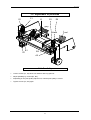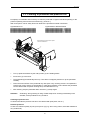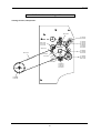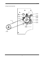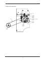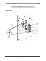
1
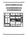
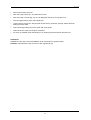
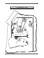
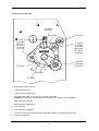
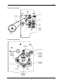
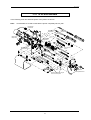
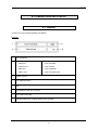
English Service manual Thermal Transfer Printer Desco II type 79.56.025 • November 2000 Carl Valentin GmbH • Neckarstraße 78-80 & 94 • 78056 VS-Schwenningen [email protected] • http://www.valentin-carl.de Table of contents Table of contents 1. Electronics ..........................................................................................................................................1 1.1. Wiring diagrams ...........................................................................................................................1 1.1.1. Wiring diagram power unit ................................................................................................1 1.1.2. Wiring diagram CPU .........................................................................................................2 1.2. Component parts of CPU (Revision 0) .........................................................................................3 1.3. Component parts of CPU (Revision A) ........................................................................................4 1.3.1. Bridge plan ........................................................................................................................5 1.4. Component parts of power supply ...............................................................................................6 1.5. Connector assignment rear panel ................................................................................................7 1.6. Changing of fuses ........................................................................................................................8 1.6.1. Primary fuse ......................................................................................................................8 1.6.2. Secondary fuse .................................................................................................................8 1.7. Check-points ................................................................................................................................9 1.7.1. Voltage supply power board .............................................................................................9 1.7.2. Voltage supply CPU ..........................................................................................................9 1.7.3. Photocells........................................................................................................................10 1.7.4. Clock signals ...................................................................................................................13 1.7.5. Motor signals ...................................................................................................................13 1.8. Service monitor ..........................................................................................................................14 1.8.1. Valuation of label parameters .........................................................................................14 1.8.2. Error message: label error ..............................................................................................15 1.8.3. Error elimination ..............................................................................................................16 1.8.4. Monitor ............................................................................................................................16 2. Options ..............................................................................................................................................17 2.1. External inputs / outputs.............................................................................................................17 2.1.1. Component parts external I/O's ......................................................................................17 2.1.2. Installation external I/O's.................................................................................................18 2.1.3. PIN assignment of DSUB connections ...........................................................................19 2.1.4. Check-points ...................................................................................................................20 2.2. PC-Card......................................................................................................................................21 2.2.1. Component parts PC-Card..............................................................................................21 2.2.2. Installation PC-Card ........................................................................................................22 2.3. RS 485........................................................................................................................................23 2.3.1. Component parts RS 485................................................................................................23 2.3.2. Installation RS 485 ..........................................................................................................23 2.4. Extension of RAM.......................................................................................................................24 2.5. Date/Time ...................................................................................................................................25 2.6. Extension of RISC ......................................................................................................................26 2.6.1. Component parts RISC ...................................................................................................26 2.6.2. Installation RISC .............................................................................................................27 2.6.3. Moveable cutter / exchange of cutting ledge ..................................................................28 2.6.4. To adjust cutter ...............................................................................................................30 2.6.5. To adjust cutter ledge......................................................................................................31 I Table of contents 3. Mechanics .........................................................................................................................................33 3.1. Exchange of printhead ...............................................................................................................33 3.2. Adjustment of printhead .............................................................................................................34 3.2.1. Parallelity.........................................................................................................................34 3.2.2. Pressure ..........................................................................................................................35 3.3. Cleaning of printhead and pressure roll .....................................................................................36 3.4. Exchange of ribbon unwinding roll .............................................................................................37 3.5. Exchange of pressure roll...........................................................................................................38 3.6. Exchange of synchroflex drive ...................................................................................................40 3.7. Exchange upper ribbon tension roll............................................................................................42 3.8. Exchange of O-belt.....................................................................................................................44 3.9. Exchange of cogged belt............................................................................................................46 3.9.1. Standard..........................................................................................................................46 3.9.2. Version: rewinding roll inverse ........................................................................................50 3.9.3. Thermal version ..............................................................................................................53 3.10. To oil and lubricate ...................................................................................................................54 4. Possible sources of error ................................................................................................................55 4.1. Display........................................................................................................................................55 4.2. Table of errors ............................................................................................................................56 II photocell cutter + cutter motor VMe ON/OFFM VCC Input/Messer VD GND Stocko6 ST 1 ST 4 Stocko2 1 12V/24V GND TCR SP RF sensor sensor sensor label VCC/TCR Input/TCR PULL/TCR GND label + ST 9 Stocko4 ST 8 Stocko4 1 - sensor ST 3 ST 6 Molex 4 ST 11 JST 8 ST 2 Stocko8 power unit + CPU N P rt M1 EI96/35,7 T1 filter NF1 power line filter block art. no. 71.55.010 Attention : safety part E00 14V~ transformer transformer art. no. 22.04.002 24V/18V supply printhead 89.901.301 Crouzet step motor 14V~ 27V~ 27V~ GND GND GND GND VDK VDK VDK VDK rt/ws gn/ws gn art. no. 70.55.015 art. no. 70.55.010 AMP 2x17 ST 7 GND Stocko4 7,6 dot printers 8 and 12 dot printers fan ST 5 1 power unit Stocko2 ST 10 Stocko4 DL label VCC/DL INPUT/DL label VCC/SP Input/SP PULL/SP GND 1 VCC/RF Input/RF PULL/RF GND 1 ext. 1 1 1 1 1 1 Winder 320V RV1 3,15A/T 230V~ Service manual 1. Electronics 1.1. Wiring diagrams 1.1.1. Wiring diagram power unit AT-keyboard foil keyboard LCD-Display 24x2 power unit & CPU CSDISPL/ GND D1 D0 D3 D2 D5 D4 D7 D6 RC5 RC6 GND VCC option plate RS485 ST14 1 2 3 4 5 5pol. pin ST14 1 2 3 4 5 5pol. pin ST6 1 2 3 4 5 6 7 8 9 10 11 12 13 14 15 16 17 18 19 20 21 22 23 24 25 26 27 28 29 30 31 32 33 34 35 36 37 38 39 40 AMP20x2 ST4 10 9 8 7 6 5 4 3 2 1 AMP5x2 printhead control Kyocera 128 12 dot ST12 AMP10x2 ST3 1 2 3 4 5 6 7 8 9 10 10pol. pin ST15 1 2 3 4 5 5pol. pin ST15 1 2 3 4 5 5pol. pin option plate dispensing I/O Art.-Nr.:70.21.005/6 CPU art. no. 70.20.007B ST13 1 2 3 4 5 6 7 8 9 10 10pol. pin ST5 AMP17x2 ST9 1 2 3 4 STOCKO4 ST7 1 2 3 4 5 6 7 8 9 10 10pin plug board AMP7x2 1 2 3 4 5 6 7 8 9 10 11 12 13 14 ST10 DUT3 GND VCC VCC ADW0 ADW1 ADW2 INP0 INP1 INP2 OUT2 OUT4 INP3 OUT0 OUT1 MOTO0 MOTO1 MOTO2 MOTO3 MOTO4 MOTO5 MOTO6 MOTO7 SRESET/ SUPPLY 12V INP4 1 2 3 4 5 6 7 8 9 10 11 12 13 14 15 16 17 18 19 20 21 22 23 24 25 26 27 28 29 30 31 32 33 34 GND GND 2 1 2 3 4 5 6 7 8 9 10 11 12 13 14 15 16 17 18 19 20 VCC GND A1 ST1 AMP25x2 50 49 48 47 46 45 44 43 42 41 40 39 38 37 36 35 34 33 32 31 30 29 28 27 26 25 24 23 22 21 20 19 18 17 16 15 14 13 12 11 10 9 8 7 6 5 4 3 2 1 12V GND VCC MA23 IORDY MA22 DEX/ MA21 IOWR/ MA20 IORQ/ MA19 WRH/ MA18 WRL17 MA17 RD/ MA16 MD15 MA15 MD14 MA14 MD13 MA13 MD12 MA12 MD11 MA11 MD10 MA10 MD9 MA9 MD8 MA8 MD7 MA7 MD6 MA6 MD5 MA5 MD4 MA4 MD3 MA3 MD2 MA2 MD1 MA1 MD0 MA0 50 49 48 47 46 45 44 43 42 41 40 39 38 37 36 35 34 33 32 31 30 29 28 27 26 25 24 23 22 21 20 19 18 17 16 15 14 13 12 11 10 9 8 7 6 5 4 3 2 1 connector strip MC-Card 25x2pol. AMP25x2 GND DTRO TXDO RXDO GND CERR GND VCC GND VCC GND VCC GND VCC GND VCC GND VCC GND GND CD0 CD1 CD2 CD3 CD4 CD5 CD6 CD7 ACK/ BUSY CPE VCC 9 8 7 6 D-SUB 9pin socket 5 4 3 2 1 RS232 (RS485) 1 2 3 4 5 6 7 8 9 10 11 12 13 14 15 16 17 18 19 20 21 22 23 24 25 26 27 28 29 30 31 32 33 34 35 36 Centronics 36pol. Service manual 1.1.2. Wiring diagram CPU Service manual 1.2. Component parts of CPU (Revision 0) 3 Service manual 1.3. Component parts of CPU (Revision A) 4 Service manual 1.3.1. Bridge plan Printhead Version Article No. Machine Jumper position JP15 Specials KCE-53 (12 Dot) KCE-107 (12 Dot) KCE-128 (12 Dot) KCE-150 (12 Dot) V5a 82.20.035 V55 a Optimized timing but lower pressure KHT-106 (7,6 Dot) V3C 82.55.006 V55 a Printhead tension 18V Adapte cable KM2004 A3 (8 Dot) (flat w/o lug) KM2004 B3 (8 Dot) (flat with lug) V3B 82.55.005 V55 b Adapter cable Option Jumper JP11 b a a a Jumper JP14 a b a a Jumper JP15 s. o. s. o. s. o. s. o. Jumper JP16 - Default Hotstart RISC Initialisation CPU via Eprom 5 Jumper JP17 (only 70.20.052 and 70.20.053 b b b a Service manual 1.4. Component parts of power supply 6 Service manual 1.5. Connector assignment rear panel 1 = Centronics interface 2 = Memory-Card slot A and B (Option) 3 = serial interface RS 232 4 = socket for PC keyboard 5 = external input 6 = external output 7 = fan 8 = power supply with ON/OFF switch 7 Service manual 1.6. Changing of fuses 1.6.1. Primary fuse The primary fuse is in the power line filter block and accessible from outside After plugging out the cover can be opened. There behind you will find the fuse-switch, which has to be pulled out to change the fuse. 1.6.2. Secondary fuse Attention: The machine should only be opened by competent staff. Plug out before removing the cover! After removing the cover the CPU plate is visible. Underneath you will find the power supply board with 2 secondary fuses. After removing the cover it will be accessible. F1: fine-wire fuse T 2,5 A F2: fine-wire fuse T 10,0 A fuse for 5 V and 12 V supply fuse for motor voltage (33 V) and burning voltage (24 V) and cutter res. rewinding unit CPU connection motor fan burning voltage transformer 8 Service manual 1.7. Check-points 1.7.1. Voltage supply power board check-point description value ST3 ST3 ST3 ST11 U10 ST3 PIN 3, 4 PIN 26 PIN 3 PIN 1-3 PIN 3 PIN 33, 34 VCC 12V 24V VDK VIN GND 5V 12V 24V 24V ~ 33V 0V ST3 PIN 25 SUPPLY 1 ~ 19V 1.7.2. Voltage supply CPU check-point description value ST5 ST5 ST5 ST5 GND VCC 12V SUPPLY 0V 5V 12V ~ 19V PIN 2, 33, 34 PIN 3, 4 PIN 26 PIN 25 9 Service manual 1.7.3. Photocells Label photocell transmission ST7: ST7: ST7: PIN 4 PIN 3 PIN 1 VIN INPUT GND ~1,2V see below 0V Depending on the transparency of the label res. backing paper the voltage at the input of the AD converter is changing. Sketch 1 shows a typical voltage wave form at "INPUT", measurable at ST5 PIN 5 (CPU). In case the adjusted value of the sending current of the photocell is insufficient, e.g. when using extremely thick or thin backing paper, it can be adjusted by changing P1 (power unit plate). Rotation to the right adjustment for thick backing paper Rotation to the left adjustment for thin backing paper The "INPUT" level can be displayed in menu item "Service functions" (label parameter) under "LS: x,x". measurement of photocell 10 Service manual Label photocell reflexion ST8: ST8: ST8: ST8: PIN 1 PIN 2 PIN 3 PIN 4 VCC INPUT PULL-UP GND 5V see sketch ~ 2V 0V The voltage wave form at "INPUT" is similar to the one described under A and is measurable at ST5 PIN 6 on the CPU. It has to be considered that the marking for the reflexion photocell must be in a distance of 32,5 mm to the interior rim, so that the photocell recognizes the marking. The "INPUT" level can be displayed in menu item "Service functions" (label parameter) under LS: x,x. The marking should have a size of at least 7 mm x 3 mm or bigger. 11 Service manual Dispensing photocell ST9: ST9: ST9: ST9: PIN 1 PIN 2 PIN 3 PIN 4 VCC INPUT PULL-UP GND 5V see sketch ~ 1,2V 0V The typical voltage wave form at "INPUT" (measurable at ST5 PIN 9) is shown in sketch 3. As standard a level of 2,5 V is adjusted. If a label is under the dispensing photocell, the level at"INPUT" must be higher than 2,5 V. If the label is removed, the voltage must lower under 2,5 V. In some cases it is necessary to change the level of the dispensing photocell. This can be done in menu item "Printer initialisation - LS switching level". The "INPUT" level can be displayed in the menu item "Service functions" (label parameter) under CP: x, x. Ribbon check ST10: ST10: ST10: ST10: PIN 1 PIN 2 PIN 3 PIN 4 VCC IN PULL-UP GND 5V High res. Low ~ 1,2V 0V The photocell "Ribbon check" checks whether the ribbon is moving. By that alterate high and low signals are measurable at "IN", which should have a ratio as much as possible of 1:1. The "IN" level can be displayed in menu item "Service functions" (label parameter) under RCR and is measurable at ST5 PIN 8 on the CPU. 12 Service manual 1.7.4. Clock signals check-point description value U1 PIN 11 PIN 12 CLK CLK 25 res. 32 MHz U30 PIN 15 PIN 16 RESET RESET 0V ~ 5V U1 PIN 24 NMI 0V CPU CPU 1.7.5. Motor signals Motor for paper feed check-point (CPU) check-point (power supply) description ST5 ST3 HC1 PIN16 PIN16 value motor on motor off 5V t from printing speed 130 mm/sec. on, otherwise HC1 signal remains on zero PIN17 PIN17 CLK1 5V t The frequency changes according to printing speed. PIN18 PIN18 DIR1 5V t defines direction of step motor PIN19 PIN19 ENABLE1 5V t release of step motor control 13 Service manual 1.8. Service monitor 1.8.1. Valuation of label parameters In function menu "Service functions" you will find the service monitor, by which the photocells can be checked res. adjusted. When measuring the labels the values will be displayed in the first line, thereby the following measured voltages are shown: A: B: C: absolute minimum (measured on backing-paper) smallest maximum (measured on label) upper/lower switching level The sketch illustrates the voltage wave form of the label photocell while measuring the label. The difference between "A" and "B" should be at least 1,5 V. 14 Service manual 1.8.2. Error message: label error Possible reasons of the error message "Label error" are the following: Too thick res. opaque backing paper In this case the value of A will be too high. This means that the printer cannot distinguish between label and backing paper. Very thin label material In this case the value of B is too low, so that the printer cannot distinguish between backing paper and label. Pre-printed label with strong differences in contrast Pre-printed labels are a particular problem. Here the fluctuations of voltage on the label while measuring are very high. In this case the value of B will be very small. In case the difference between B and A is too small, the printer is not able to measure the label. 15 Service manual 1.8.3. Error elimination In case the photocell had already been adjusted so that the difference between A and B has received the highest possible value (as described in chapter "1.7.3. Photocells") the "sensitivity of the label photocell" can be adjusted. 1.8.4. Monitor After activating the key again in menu "Parameter of label photocell" the photocell monitor will be activated. On the display of the printer the following appears: The digit represents the measured voltage in volts. The monitor serves to check the label photocell to its function. As well it is possible to move the label manually under the photocell to get an idea of the voltage wave form and to be able to judge whether the label can be measured. The difference of backing paper and label should be higher than 1,5 V. 16 Service manual 2. Options 2.1. External inputs / outputs 2.1.1. Component parts external I/O's 17 Service manual 2.1.2. Installation external I/O's Connect circuit board with components to the CPU. Mount the connecting cable at the rear panel and connect it to the circuit board (position of connectors on rear panel, see chapter "1.5. Connector assignment rear panel"). A = dispense inputs B = dispense outputs 18 Service manual 2.1.3. PIN assignment of DSUB connections a) Inputs (9-pin DSUB plug) Pin 1 6 7 2 8 9 4 3 + + + + - description of signal INPUT 1 INPUT 2 INPUT 3 INPUT 4 b) Outputs (9-pin DSUB receptacle) Pin 9 5 8 7 6 2 4 3 + + + + - internal description of signal OUTPUT 1 OUTPUT 2 OUTPUT 3 OUTPUT 4 external plug DSUB + Pin optical coupler The in- and outputs are galvanic separated and have to be fed by external power supplies. In function menu "Service functions" the in-/outputs can be checked. IN-12345678 OUT-12345678 ------------------------In case an input is activated this will be shown in the display. If an output is to be activated this can be done by pressing the key of the desired output (e.g. activation of output 3, press key 3). The output is deactivated by pressing the key again. 19 Service manual 2.1.4. Check-points check-point description value 4 x IN (1 - 4) ext. input impulse U6 PIN2 INPUT 1 PIN4 INPUT 2 PIN6 INPUT 3 PIN8 INPUT 4 4 x OUT (1 - 4) U3 PIN2 OUTPUT 1 PIN3 OUTPUT 2 PIN6 OUTPUT 3 PIN7 OUTPUT 4 20 12-24V Service manual 2.2. PC-Card 2.2.1. Component parts PC-Card k D3 D2 k D4 D1 k k C6 + ST3 Q4 R24 R25 Q6 Q2 C2 ST5 Q1 C18 + R13 C4 Q3 R7 C10 Q5 PNW1 C1 C9 U9 U8 C18 U6 U7 U5 U10 C15 C13 JP6 JP7 R26 R27 + C17 C3 RNW2 RNW4 RNW3 ST8 RNW1 + C5 U4 Q7 C14 PNW2 C11 C12 C8 C7 U1 U2 U3 ST4 ST2 ST1 21 Service manual 2.2.2. Installation PC-Card Switch off the printer. Open cut-out of rear panel for PC-Card board. Install PC-Card board (see sketch) and insert connecting cable. 22 Service manual 2.3. RS 485 2.3.1. Component parts RS 485 2.3.2. Installation RS 485 Connect circuit board with components on CPU (see sketch above). Screw connecting cable to rear panel (position of RS 232) and connect it to circuit board (position of connecting plug on rear panel see chapter "1.5. Connector assignment rear panel"). 23 Service manual 2.4. Extension of RAM Installation: Switch off the printer. Insert SIMM modules into socket. The modules always have to be installed in pairs, either in the two inner or the two outer plugging positions. 24 Service manual 2.5. Date/Time solder in battery CPU vario Installation: Switch off printer and remove CPU. When soldering in battery B1 pay attention to direction of polarization! Insert RTC 72421A in socket (note the marking PIN1!). Reinstall CPU and set the time in menu item "Date/Time" (see operating manual). 25 Service manual 2.6. Extension of RISC 2.6.1. Component parts RISC 26 Service manual 2.6.2. Installation RISC Switch off the printer. Remove components U15 and U13. The font Eprom U31 may as well be removed as the RISC processor disposes of an own font Eprom. Loosen mounting screws at the board and screw in spacers. Put RISC board into socket ST8 and fix it with mounting screws. Switch on the printer. Besides the printer type the display additionally shows the identification '++' for the RISC processor. 27 Service manual 2.6.3. Moveable cutter / exchange of cutting ledge Note: The points marked are to be oiled 3 times a year ! I J L A B K D E C motor H G A F molykote oil 28 Service manual Attention: Danger of injury while working at the cutter! Switch off machine, plug out! Open right cover. Remove 4 screws (A) and take off front plate above (C). Remove nut (B) and take off holding shaft. Fix spring (D) at magnetic adjusting screw (E). Take off locking washer of the inner side of bearing lever of cutter (F). Pull bearing shaft (G) outwards. At the same time take off the complete moveable cutter (F + H) to the front. Attention: Do not loose 2 spacer rings on the bearing shaft! Remove two screws (I). Take off cutting ledge (J). Attention: Pay attention to position of slide bearing (K) with integrated intermediate (L), in case they will loosen. On the right side of the cutting ledge the intermediate loosens too. Pay attention to position. Installation: Install (sharpened) cutter in opposite order. Adjust cutter according to chapter "2.6.4. To adjust cutter". 29 Service manual 2.6.4. To adjust cutter A D C motor B Switch off machine, plug out! Open right cover. Loosen 2 screws (A) about 1 rotation. Insert screwdriver (B) according to sketch. (control: While pressing down the screwdriver the moveable cutter (C) has to move upwards.) Press down screwdriver, so the left upper edge of the moveable cutter (C) stands about 0,5 mm above the lower edge of the cutting ledge (D). Move the cutting ledge (D) towards the moveable cutter (C) and fix both screws (A) again. Insert a piece of paper or label and check with the screwdriver, if the cutter cuts correctly. If not, repeat the steps. 30 Service manual 2.6.5. To adjust cutter ledge Caution: Danger of injury while working at the cutter! Switch off printer, plug out! Remove small front panel (A) after removing the 2 screws (B). Take off the 2 countersunk screws at the front panel (C) and remove it. Loosen counternut (D). Insert a piece of paper or labels between lower plate (E) and fixed cutter ledge (F), then manually push the movable cutter ledge (D) upwards and control the cutting. Attention: The cutter has to start cutting approx. 5 mm from the left edge of the fixed cutter ledge. 31 Service manual The cutter cuts further on the right side: Tilt the movable cutter ledge (G) to the front (Caution: danger of injury!) and turn adjusting screw (H) in clockwise direction until the nominal position is reached. Push back the cutter ledge. The movable cutter ledge (G) strikes the fixed cutter ledge (F): Tilt the movable cutter ledge (G) to the front (Caution: danger of injury!) and turn adjusting screw (H) against clockwise direction until the nominal position is reached. Push back the cutter ledge. Tighten counternut (D). Reinstall front panel (C) and small front panel (A). Turn on printer and test cutter function. 32 Service manual 3. Mechanics 3.1. Exchange of printhead Attention: For exchange of printhead the ESD regulations have to be observed! Before working at the printhead you have to accomplish safety control against electrostatic charge! Switch off machine, plug out! Lift printhead bracket with printhead by turning knurled knob (A) clockwise. Pull off printhead plug (B1, B2) including cables. Considering machines with dispenser: screw off dispenser photocell. Unscrew screws (C1, C2) about 3 rotations by a ring spanner, thereby pay attention to the position of printhead for the purpose of reinstallation. Press latch lever (D) backwards and draw off printhead (E) to the front. Installation: Install the new printhead with placed screws (C) in opposite order. Attention: Do not touch the contacts of the printhead! While installing pay attention, that thermistor cable lies in the cut-out provided for. Pay attention to the correct fit of the printhead (guiding). 33 Service manual 3.2. Adjustment of printhead C1 D1 E C2 D2 grey black B1 A1 B2 A2 3.2.1. Parallelity Loosen screws (A1, A2) about 1/2 rotations with ring spanner. Adjust parallelity by screws (B1, B2). Depending on the print quality adjust more, until the print quality is correct. Tighten screws (A1, A2) again. 34 red Service manual 3.2.2. Pressure Avoid increase of printhead pressure as much as possible, because a pressure too high damages the printhead and decreases its life time. Print quality too faint (even when using highest contrast): Release lever (E) or after loosening counter nuts (C1, C2) increase the pressure with adjusting nuts (D1, D2). 35 Service manual 3.3. Cleaning of printhead and pressure roll Principally it is advisable and necessary to clean the printhead in regular intervals depending on the printer's operating hours and its environment (e.g. dust etc.). With a test print it can be easily found out whether the printhead is soiled or defective. a) printhead is o.k. b) printhead is defective/soiled While cleaning the print head, the printer has to be switched off ! 1 3 2 4 Turn up printhead bracket by the rotary button (4) as if loading labels. Press lever (1) to the back. The printhead (2) automatically turns up. If this does not happen please turn up the printhead carefully. Clean the lower surface of the printhead only with spirit or dry cleaning solvent. As expedient a close-woven cotton cloth is recommended. In case this procedure is not sufficient the printhead can be cleaned with a special cleaning foil (to be obtained from us). After cleaning clap the printhead down until lever (1) snaps again. Attention: Scratching, strong rubbing of using of hard subjects for cleaning is absolutely to be avoided, as the printhead is very sensitive. Cleaning of pressure roll: In certain intervals the pressure roll has to be cleaned with spirit (dust, soil etc.). Increase pressure: In case of insufficient quality of print, pull up lever (3) (e.g. when using carton, thick label material or very small fonts). 36 Service manual 3.4. Exchange of ribbon unwinding roll D C B A Switch off machine, plug out! Take off locking washer (A). Turn roll (B) clockwise and pull it outwards the pillar (D) at the same time. Attention: Danger of injury at thin spring steel plate. In case spring (C) remains in unwinding roll, pull it outside with rotary motion at the same time. Installation: Lubricate pillar (D) and push spring approximately to the middle of the pillar (if possible a new one) Lubricate spring from outside. Turn the ribbon unwinding roll by clockwise rotations onto the spring. After approx. 10 rotations press the roll far inside and fix locking washer. 37 Service manual 3.5. Exchange of pressure roll G5 G4 I1 H3 E CPU board H4 Z motor H2 I2 L F J1 H1 K J2 C4 C3 B G3 transformer cover of power unit M D3 D4 G2 G1 C1 power unit plate C2 D1 A1 D2 A2 View Z: N O P 38 Service manual In connection with the exchange of the pressure roll, the complete printer mechanics should be oiled and lubricated (see chapter "3.10. To oil and lubricate"), as the lubrication points are free accessible after the following instructing steps. Switch off machine, plug out! After removing screws (A1, A2), take off left cover. After removing 4 screws (B), only one is displayed, take off cover of power unit. Pull off all cable plug connectors from power unit plate. Attention: Pay attention to the position of the plugs for the purpose of reinstallation! After removing nuts (C1 - C4), take off power unit plate. Loosen screws (D1 - D4) and take off transformer. Pull off cable plug connectors JP9 / JP10 / JP12 / JP14 / (JP11) from CPU board. (Specifications see circuit board and cable) Attention: In spite of specification pay attention to the position of the plugs for the purpose of reinstallation! Pull off cogged belt (E) from return pulley (F) and remove it from rewinder (M). After removing the hexagonal head screw take off return pulley (F). Therefore hold return pulley at the opposite side and take it off, too. After removing nuts and screws (G1 - G5) take off the complete print mechanics to the right hand side. Attention: While screwing off the nuts and screws pay attention to the print mechanics, so it will not fall down. After removing screws (H1 - H4) take off the motor. Thereby remove short cogged belt (L). Attention: While taking off the motor, the two Delrin belt drives (I1, I2) will be loosened. Loosen locking screws (J1, J2) and take out pair of belt drives (K) with spacer piece and ball bearing. Take off locking washer (N) and ball bearing (O) on the other side of the shaft. Then take out downwards pressure roll (P) of the print mechanics. As much as possible clean the ball bearing in dry cleaning solvent and then lubricate new! Oil and lubricate the complete print mechanics according to chapter "3.10. To oil and lubricate". If necessary the upper ribbon tension roll can be exchanged at the same time (see chapter "3.4. Exchange of ribbon unwinding roll"). Installation: Installation of the new roll and reinstallation of all components in opposite order. Regard that locking screw (J1) meets milled surface of the roll. 39 Service manual 3.6. Exchange of synchroflex drive F B D E CPU-board direction motor C 180° rotated cover of power unit A1 A2 Switch off machine, plug out! Take off left cover upwards after removing both screws (A1, A2). Remove screw (B), thereby hold bed bolt (C) with a slotted screwdriver on the opposite side. Remove screw (D) together with bracket (E). Take out synchroflex drive (F), whereby at the same time you have to take off the O-belt from the driving gear on the inner side of the print mechanics. 40 Service manual Installation: Installation of the new drive and reinstallation of all components in opposite order. While installing pay attention to the correct fit of the belts. Insert the synchroflex drive centric into the boring provided for, otherwise it will grind. Attention: The integrated grooved ball bearing has to catch the cogged belt drive clockwise (according to the sketch). Otherwise, place cogged belt drive with the bearing the other way around. 41 Service manual 3.7. Exchange upper ribbon tension roll F E1 Z E2 C CPU-board motor D B transformer cover of power unit power unit plate A1 A2 View Z: H G 42 Service manual Switch off machine, plug out! After removing screws (A1, A2), take off left cover. After removing 4 screws (B), only one is displayed, take off cover of power unit. Pull off cogged belt (C) from return pulley (D). Loosen locking screws (E1, E2) and pull off belt drive (F) with belt, spacing washer and ball bearing from the shaft. Take off locking washer (G) on the other side of the shaft. Take out tension roll (H) of the print mechanics. As much as possible clean ball bearing in dry cleaning solvent and then lubricate new. Installation: Installation of the new roll and reinstallation of all components in opposite order. Attention: Pay attention to the correct fit of the cogged belt (C)! 43 Service manual 3.8. Exchange of O-belt B D E C G F A 44 Service manual Switch off machine, plug out! Open right cover. By turning the knurled knob (A) counter clockwise, press down the printhead. Take off locking washer (B). Pull off O-belt (C) from ribbon unwinding roll (D) and take it out. Carefully lever the printhead bracket (F), according to the sketch with screwdriver (E) (e.g. size 6) to the front. At the same time pull off manually or with second screwdriver O-belt from synchroflex drive (G). Installation: Installation of the O-belt in opposite order. Attention: Lever away printhead bracket (F) just as much as necessary, so nothing gets bent. Pay attention to the correct running of the O-belt (see sketch). No lubricant onot O-belt (if necessary clean it). 45 Service manual 3.9. Exchange of cogged belt The printer desco II had been delivered in several versions. The difference is the running of the belt. Following the different versions are shown in picture. The steps to exchange a belt are as much the same, so they will only be described detailed for the standard version. 3.9.1. Standard 7,6 dot printer (long belt) 45.15.030 59.02.216 12.10.016 16.15.013 48.01.003 50.01.046(2x) 72.15.011 50.01.049 59.03.030 MOTOR 59.03.150 10.15.005 59.02.214 10.40.032 72.15.006 12.10.016 16.15.013 48.01.003 72.15.001 71.15.036 10.40.023 72.15.016 50.01.012 50.01.061 46 12.10.016 48.01.003 50.01.012 50.01.094 59.02.211 Service manual 7,6 dot printer (short belt) 12.15.010 59.02.215 59.03.050 10.10.006 50.01.074 16.15.011 12.10.016 16.15.080 72.15.013 72.15.012 12.15.042 41.01.002 48.01.004 50.15.010 10.40.032 72.15.005 50.01.049 50.15.010 71.15.036 59.03.030 72.15.001 Switch off machine, plug out! Take off the left cover. Take off cover of power unit. Pull off all cable plug connectors from the power unit plate. Attention: Pay attention to the position of the plugs for the purpose of reinstallation! Take off power unit plate. Remove defect cogged belt. Take off motor. Take off short cogged belt. In case of need, pull off belt drive from shaft after screwing off the two locking screws. Take off cogged belt. 47 Service manual 8 dot printer (long belt) 45.15.030 59.02.216 72.15.011 50.01.049 12.10.016 16.15.013 48.01.003 50.01.046(2x) 59.03.036 72.15.001 10.15.005 59.02.214 59.03.150 50.01.035 10.40.032 72.15.003 12.10.016 16.15.013 48.01.003 71.15.136 59.02.214 12.10.016 50.01.005 10.10.006 12.10.016 47.05.001 48.01.003 50.01.012 50.01.065 50.01.094 59.02.211 10.40.023 72.15.016 50.01.012 50.01.061 8 dot printer (short belt) 12.15.010 59.02.215 59.03.050 72.15.013 10.10.006 50.01.074 16.15.011 12.10.016 16.15.080 72.15.012 12.15.042 41.01.002 48.01.004 50.15.010 10.40.032 72.15.002 50.01.049 50.15.010 71.15.136 59.03.036 72.15.001 59.02.214 12.10.016 50.01.005 10.10.006 48 Service manual 12 dot printer (long belt) 45.15.030 69.10.001 59.02.216 48.02.004 48.01.004(4x) 50.01.065(5x) 72.15.011 50.01.049 12.10.016 16.15.013 48.01.003 50.01.046(2x) 59.04.071 MOTOR 59.03.150 10.15.005 48.15.435 10.15.305 59.02.214 50.01.065(3x) 48.01.430 10.40.032 72.15.302 71.15.136 12.10.016 16.15.013 48.01.003 72.15.301 10.15.005 48.01.430 12.10.016 48.01.003 50.01.012 50.01.094 59.02.211 10.40.023 72.15.016 50.01.012 50.01.061 12 dot printer (short belt) 45.15.030 69.10.001 48.01.004(4x) 50.01.065(5x) 59.02.215 48.02.004 72.15.013 72.15.012 12.15.042 41.01.002 48.01.004 50.15.010 10.40.032 59.03.050 MOTOR 10.10.006 50.01.074 16.15.011 12.10.016 16.15.080 48.15.435 10.15.305 50.01.065 48.01.430 72.15.303 10.40.032 71.15.136 72.15.301 59.04.071 10.15.005 48.01.430 49 Service manual 3.9.2. Version: rewinding roll inverse running of belt 7,6 dot printer: 59.02.215 72.15.013 50.01.035 48.01.420 16.15.010 12.10.016 MOTOR 12.15.042 72.15.012 50.15.010 10.40.032 41.01.002 48.01.004 48.04.015 16.30.002 10.15.006 48.01.435 59.03.115 71.15.036 72.15.005 50.15.010 50.01.049 72.15.001 59.03.030 16.15.010 12.10.016 10.10.006 48.01.435 72.15.009 10.15.035 50 Service manual running of belt 8 dot printer: 59.02.215 72.15.013 50.01.035 48.01.420 16.15.010 12.10.016 MOTOR 48.04.015 10.15.005 12.15.042 72.15.012 50.15.010 10.40.032 41.01.002 48.01.004 16.30.002 10.15.006 48.01.435 59.03.115 71.15.136 72.15.002 50.15.010 50.01.049 72.15.001 59.03.036 10.15.005 59.02.214 16.30.020 48.01.435 72.15.009 10.15.035 51 (10mm abgedreht) Service manual running of belt 12 dot printer: 59.02.215 59.04.071 72.15.013 48.01.420 16.15.010 12.10.016 MOTOR 72.15.012 12.15.042 41.01.002 48.01.004 50.15.010 10.40.032 16.30.020(0.5mm abdrehen) 10.15.305 48.01.430 59.03.115 72.15.301 72.15.303 50.01.049 50.15.010 16.15.010 12.10.016 10.10.006 48.01.430 72.15.009 10.15.035 52 Service manual 3.9.3. Thermal version only 8 dot printer running of belt: 59.03.036 16.15.011 MOTOR 10.15.005(3x) 59.02.214 59.03.124 50.01.074 71.15.136 72.15.003 72.15.001 59.02.211 50.01.005 59.02.214 12.10.016 10.01.006 48.01.435 50.01.094 12.10.016(2x) 50.01.012 10.40.023 50.01.012 50.01.061 72.15.016 53 Service manual 3.10. To oil and lubricate In the following all oil and lubricate points of the printer are shown. Note: It is advisable to oil and to lubricate the printer completely twice a year! Molykoteoel Molykoteoil Fett lubricant Molykoteoel Molykoteoil Molykoteoel Molykoteoil Molykoteoel Molykoteoil Molykotefett Molykotelubricant duennes Oel thin oil Fett lubricant Molykoteoel Molykoteoil Fett lubricant Molykotefett Molykotelubricant Walzen mit Spiritus reinigen clean rolls with spirits 54 Service manual 4. Possible sources of error 4.1. Display In case of error the following display will appear: Example: 1 Error categories 2 unknown error label error system error data error ribbon error error interface error field data error memory error parameter error print parameter Number of error The number of error is indicated, see table of errors chapter "4.2. Table of errors". 3 Text Specification of the error occured. 4 Line number, MC-Slot Indication where res. in which line the error occured. 55 Service manual 4.2. Table of errors number possible causes of error 1 2 3 4 5 6 7 8 9 10 11 12 how to solve the problem line completely/partly projects the upper label rim line completely/partly projects the lower label rim line completely/partly projects the left label rim line completely/partly projects the right label rim one/more characters of the text is/are not included in the selected font one/more characters of the text is/are not included in the selected font impossible to match the text into the selected field place the line in a lower position (Y) check rotation, font place the line in a higher position (Y) check rotation, font move the line to the right (X) check rotation, font move the line to the left (X) check rotation, font change text change font change text change font check field size internal error Please contact your distributor. the selected type of text is not available check type of text the selected code is not available check type of code the selected position is not available check position the selected font is not available check font check language 13 the font EPROM does not support the selected language Please contact your distributor. 14 15 16 17 18 error in font EPROM Please contact your distributor. error in font EPROM Please contact your distributor. error in font EPROM Please contact your distributor. error in font EPROM Please contact your distributor. 56 Service manual number possible causes of error 19 20 21 22 how to solve the problem when measuring label the difference between label and backing paper is too small when measuring no label found adjust label photocell (distributor) change sensitivity remeasure the selected label length is too high check label length while printing no marking/gap found check label while printing ribbon is empty change ribbon defective ribbon photocell loss of data at serial interface (RS 232) check ribbon sensitivity check Baudrate parity error 24 stopbit error 25 26 27 received line number invalid with RS 232 / Centronics invalid length of received mask statement check ribbon photocell in menu service 23 check cables (on printer and PC) check parity check Baudrate check cables (on printer and PC) check stopbits check Baudrate check cables (on printer and PC) check data sent connection PC - printer check data sent connection PC – printer check data sent connection PC – printer invalid mask statement missing ETB check data sent invalid length of received code statement check data sent connection PC – printer check data sent 28 29 30 31 invalid length of received command statement 57 connection PC – printer connection PC – printer Service manual number possible causes of error how to solve the problem illegal statement 32 33 34 35 36 37 38 39 40 41 42 entered number of characters invalid with EAN/UPC Code < 12; > 13 type of check digit not available with selected code connection PC – printer recalculate check digit check code data check SC code check number of characters check digit control check type of code not readable printer parameter check serial EEPROM (service) printer parameter cannot be stored check serial EEPROM (service) selected zooming factor invalid check zooming factor entered sign of offset invalid check offset value entered offset value invalid check offset value printhead temperature too high contrast 44 46 47 selected SC code invalid with EAN/UPC check data sent 43 45 entered/received check digit is faulty in check digit control defective temperature sensor of printhead error cutter, paper jam entered characters are not conform to the characters allowed by the application identifiers application identifier not available with EAN 128 continuous mode selected, printer received a command statement via interface, where number of lines < 2. Label length is missing. change printhead (service) check label guiding check cutter check code data check code data do not select continuous mode or transmit dummy line with Y-coordinates = label length (see interface manual) connection CPU – Memory-Card interface has been interrupted check connection CPU – Memory-Card interface Memory-Card interface defective check Memory-Card interface 58 Service manual number possible causes of error 48 49 50 51 52 53 54 how to solve the problem Memory-Card not or not correctly entered wrong type of Memory-Card entered (8/16 Bit) charge of battery / accumulators can cause loss of data on the Memory-Card battery / accumulators empty "Write-Protect"-switch on Memory-Card is on position "ON" Memory-Card not formatted no files on Memory-Card file does not exist on Memory-Card enter Memory-Card check card type (has to be 16 Bit) change battery (attention, loss of data!) change battery (attention, loss of data!) deactive write protection formate Memory-Card 55 56 57 58 59 60 61 62 63 64 65 invalid characters in the file name max. storage space of Memory-Card is reached max. number of main directory entries is reached search through the contents of the Memory-Card and select the desired file name check directory and device check characters use a new Memory-Card delete files on Memory-Card that are no longer needed at least one main directory entry has to be deleted, then create subdirectories selected file includes no graphic dates check file name selected file includes no label dates check file name invalid directory name check directory name selected directory already exists check directory name you tried to delete the actual directory change directory directory to be deleted is not empty first delete all files in the directory selected subdirectory does not exist check directory name 59 Service manual number possible causes of error 66 67 68 69 70 71 RTC function has been selected, though no RTC is installed in the printer RTC defective no print memory found how to solve the problem max. storage space of Memory-Card is reached check selected function, add RTC ram exchange RTC ram check memory standard on CPU board delete files that are no longer needed internal error Please contact your distributor. wrong format entered for variable line check format string wrong format entered for date/time check format string Please contact your distributor. Please contact your distributor. check connection scanner / printer 72* 73* 74* 75* 76 77 78 79 80 81 different software standard of graphics processor / main processor different software standard of graphics processor / main processor or hardware error connected barcode scanner signals device error bad print quality printhead completely soiled or defective printing speed too high scanned character sequence is not identical with character sequence to be printed, due to possibly missing dots a false barcode was printed definition of counter variables invalid, entry of inadmissible characters as counter * IDS error 60 check scanner, possibly defective increase contrast clean printhead or exchange if necessary decrease printing speed exchange printhead check characters of counter in text statement check counting mode