1
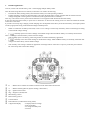
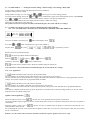
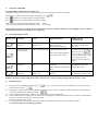
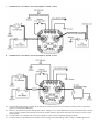
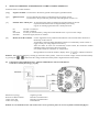
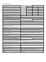
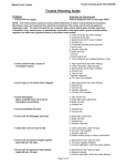
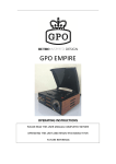
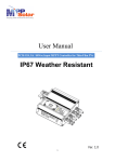
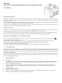
MB-3688 120A 12V/24V DC PROGRAMMABLE DUAL BATTERY ISOLATOR User Manual Warning and Precautions MB-3688 is built with corrosion resistant material and the main electronic assembly is well sealed inside the die cast alloy This unit is not designed for environments that would allow water to come in contact with the terminals on the housing which result a short circuit. The unit can be installed in any position but make sure that there is sufficient ventilated space around the unit to allow dissipation heat at the surface, a minimum of 50mm surrounding space is required. When use with lead acid battery, make sure there is sufficient ventilation for the battery which can emit harmful & explosive and away from any possible spark or naked fire such as cigarette. Cable Sizes and Fuses Cables used at each positive terminal must be of sufficient rating. Under sized cables would affect the performance of the unit and shortens the life span. Wires connected to control or signal ports carry less than 0.5 Amp. Fuses or circuit breakers of appropriate rating must be installed at positive terminal of the house battery and main battery. These fuses are for the safety and protection of the vehicle’s electrical system in case of a short to the negative ground. Warning for using the Remote Over-ride to start the vehicle Always check if the house battery bank has sufficiently higher voltage than the main battery to do the job by pressing the buttons when the unit is at OFF mode. If house battery voltage is lower than the main battery, it would not work and deplete the Main (starting) battery further. Large current will generate high heat on the cable and terminals during the cranking so do not over crank. Allow sufficient time after first Over-Ride has been done. It pays to investigate the real cause for the failure of starting the car and the draining out of the starting battery. 1. General description This dual battery isolator is designed to be customized to meet your vehicle’s specific application. The DC power system of various types alternator, main battery, house battery and loading usage are numerous and also change with time. It features the fine tuning of key voltages, delay time set points and constant monitoring of each battery to provide the maximal charging and protection of your batteries. The reliable and efficient Mosfet switching has minimal voltage loss resulting much less generated heat than diode based isolators. Microprocessor Controlled circuit provides accurate monitoring, finer tuning of voltage, delay timer set points and more fail safe protection with diagnostic display. 2. Advanced Features ● Alert Voltage: The additional Alert Voltage setting is to monitor the main battery voltage even when the unit in isolated mode and when the main battery voltage drops below the set Alert Voltage, the Remote LED Module will out slow flashes to alert end user. Remote LED Module with Over-Ride With the supplied Remote LED module w Over-Ride accessory, end user is constantly informed about the status of the Isolator whether it is in Connection Mode, Isolation Mode, Main Battery is above or at Alert low level and Isolator is in Protection Mode. Selectable 12V or 24V system Selectable Ignition Control Wide range of programmable threshold voltages (connect, isolate, alert) with high resolution and respective delay time. Monitoring of Main and House battery voltage in Isolation Mode. ● ● ● ● ● 3. Intended Applications: Caravan, vehicle with second battery, solar / wind charging multiple battery banks. This unit when using between two batteries, it functions as an isolator as following: • It isolates the main (starting) battery from the house battery in normal operating condition. • It allows charging (connect) of the house battery only when the main battery voltage is higher than the selected Connect Voltage setting and or when ignition is switched on (if this Ignition function is selected). This way, it also diverts excess power from the alternator to run equipment that feeds from the house battery. It does not allow the house battery to power the car electronics or feed into the starting of the car unless the manual Over-Ride Connection is activated. It prevents excessively large charging current dumping into the depleted house battery from the main battery and rapid repeated on-off by appropriate setting of the threshold voltages and delay times. • When it is used with one battery and a load, it acts as a low voltage cut off to keep the battery from over discharge according to the selected voltages setting. • until Normally Open uses Connect Voltage as threshold voltage. Main and House battery are normally disconnected voltage at the main battery reaches Connect Voltage. This Normally Open is the factory preset and good for the isolator dual battery application. • Normally Close uses Isolate Voltage as the threshold voltage. Main and House battery are normally connected until voltage at the main battery reaches Isolate Voltage. • This normally close setting is suitable for application with single load or connection is a priority in the first place until the DC source drops below the Isolate Voltage R = Remote Over-ride Port for manual connection of the main and house terminal A = Remote Alert Signal Port (System Voltage, 100mA max.) Ign. = Ignition Control Port Neg. = Negative (Ground) Port Main battery positive House battery positive Control buttons LED indicators (to indicate the setting status) 3 digits LED display - to display batteries voltage - status (ON/OFF) - set voltage and delay time - set menu 4. Programming Operation of MB-3688 There are 3 types of Set Menu Mode: Mode 1 is for selection of 12V or 24V when the unit is first activated. Mode 2 is for adjusting the threshold values of voltages and the related delay time. Mode 3 is to confirm change of system state such as normal open/ close, ignition control and return to default factory setting. The product will automatically exit with the new settings or return to the last set values after 10 seconds for Mode 1 and 20 seconds for Mode 2 and 3. First activate the unit by connecting Main Terminal to Positive and Neg. to Negative of a 12V battery for 12V system and 24V battery for 24V system. 4.1 Set Menu Mode 1 ------ Setting of 12V or 24 V system Press the / button to toggle 12V or 24V shown on Display. Confirm your selection by pressing the button for 12V system to button for 24V system for a few seconds. Display will show the software version to confirm setting then the battery voltage. If no selection is done within 10sec., unit will go back to last set system voltage. Remark: You have about 10 seconds to confirm your setting otherwise the product will go to the last set system voltage or factory default setting. 4.2 Set Menu Mode 2 ------ Viewing the Connect Voltage/ Isolate Voltage/ Alert Voltage/ Delay Time This is the most used Set Menu Mode. You have to pair the top LED “VOLT”, “SEC” with the bottom LED “connect”, “isolate” & “alert” to interpret the reading on the Display as shown in the following diagrams. To enter into this mode Press both Connect Voltage. and button simultaneously until display shows You can review the last set values of Connect, Isolate, Alert Voltages, Delay Times and etc. by toggle the (forward) or ( back) buttons and take note the pair of lit up LEDs Connect Voltage (Default 13.7V for 12V system) Connect Delay Time (Default 5sec) Isolate Voltage (Default 12.8V for 12V system) Isolate Delay Time (Default 5sec) Alert Voltage (Default 12.0V for 12V system) Alert Delay Time (Default 10sec) then the factory default 4.3 Set Menu Mode 2 ------ Setting the Connect Voltage / Isolate Voltage / Alert Voltage / Delay Time The procedure is same for setting and adjusting all the above parameters. Example: Setting Connect Voltage During the Review stage as in 4.2, toggle the To set the Connect Voltage press both or and button to get to Connect Voltage position. button simultaneously again so that the displayed connect voltage flashes. Press or button to increase or decrease the connect voltage to your desired voltage level. Press both buttons simultaneously until display becomes solid to confirm new setting. Continue to do other setting in the same way. The product will return to exit from Set Mode 2 automatically after 20 seconds with the new settings. 4.4 Set Mode 3 for change of system controls as indicated in the (yellow imprints) N.O. / N.C. (Normally Open / Normally Close), INGNITION CONTROL, FACTORY DEFAULT Get to the Set Mode 2 first then press Press both & button until Display shows button simultaneously to get to SET MODE 3 Display shows first, then or , , as Up button is pressed. Return to the Factory Default Example: Press both Up & Down button simultaneously Flashing / Confirm by Press both toggle by & or button to button simultaneously become solid to confirm return to the factory default setting has been done. Unit will return to exit from Set Mode 2 automatically after 20 seconds with the new settings. N.O. / N.C. Application MODE (Normally Open) This is the factory default mode. The two terminals are normally isolated, (disconnected, open) when the unit is powered up. The two terminals will be connected when the voltage at the main battery terminal is detected to be at the programmed "Connect Voltage" level (LVR) and after the set programmed DELAY TIME. MODE (Normally Close) This mode is selectable. The two terminals are normally connected, close when the unit is powered up. The two terminals will be disconnected, isolated, opened when the voltage at the main and after the set programmed DELAY TIME. This mode is commonly used for battery protector application. The load will be on until the voltage of battery or other dc source drops below the set isolated voltage level. Ignition Control application When the ignition control is set to , the unit only can be operated with car ignition switched ON. The factory default setting of Ignition Control is at OFF mode, that is the unit is in operation all the time even when car ignition is switched off. When the ignition control is set to , the unit can only be operated with car ignition is switched on and when the car is switched off the unit is also off. See wiring diagram in section 6 for connection from Ignition Control Port (3) to the car’s electrical point which has current when the car is switched on. Remark: over-ride switch will connect main and house terminal irrespective ignition control is on or off. 5. Operation of MB-3688 The LED display and Remote Alert signal port Normally the display is turned off to conserve energy, press any one of the two buttons to operate: When unit is in isolated (disconnect) mode, the display shows Press Button to view Main (battery) terminal voltage Press Button to view House (battery) terminal voltage. . When unit is in Connected mode, the display shows . Only one voltage (shared by both terminals) is shown on the display. Status of the unit such as Connect, Isolate, Protection can also be remotely indicated by the supplied accessory Remote LED Module connected to the Remote Alert signal port. 5.1 Protection Diagnosis Table Display Icon Protection Causes Suggested Solution Self-Recoverable or Manual Reset Over Voltage Protection Main Terminal Voltage >16V Check DC source voltage to main terminal . Check load at terminal Unit is self-recoverable when main battery voltage lower than 15.5V Over Current / Over Load Protection Over Current >120Amp Check house battery level. Unit is self-recoverable after 1 Look for possible intermittent short circuit in the wiring. minute. In case of occurs 3 times in a row, a final protection will lock up the unit until complete reset by disconnect and reconnect the battery. Over Temperature Protection Unit Over Temperature 90°C Check location of unit is well Unit is self-recoverable when ventilated. internal temperature cool Check cable size is sufficiently down to below 70°C rated. Low Voltage Protection Main Terminal Voltage <8V Check main battery status and alternator. Unit is self-recoverable when the main battery voltage >10V. Remark: The above voltage setting in the table is only for 12V system, the voltage setting is double for 24V system. 6. Installation notes: 6.1 The unit is factory default as Normal Open . In case you want to use the unit as Normal Close, please go to the set mode and set the unit to 6.2 The Ignition Control feature is factory default as OFF. In case you want to control the unit by car ignition switch, please go to the set mode and set the Ignition control to . 6.3 The recommended cable size is AWG#5 with 1M in length and 3% acceptable loss. 6.4 Always double check the tightness of all connections by wiggling the connected terminals and etc. Connectors and fasteners are prone to vibration loosening in a moving vehicle. Loosen connections cause sparks. 6.5 It is recommended to install a fuse with suitable rating connected to the battery positive terminal for safety. !! CAUTION: Surface is hot during operation 7. Installation for a Two Battery System (Example for 12VDC system) 8. Installation for a One Battery System (Example for 12VDC system) 8.1 The selected Isolate Voltage is usually lower than the two battery system since the unit here is mainly used as a protection against over discharging the battery. 8.2 However, the selection of Isolate Voltage and Connect Voltage are very much affected by the type of load and relative battery capacity. Select a higher Isolate Voltage for relatively smaller load; for high initial draw load such as Motor, choose a lower Isolate Voltage. 8.3 It is advisable to use a higher value of Connect Voltage to ensure a more completed charging operation. 8.4 Check the battery’s specifications for suitable Connect Voltage and Isolate Voltage and in cycling or standby applications. 9. MANUAL FOR WIRING AND OPERATION OF THE CONTROL TERMINALS Functions of the 4 Control terminals [Neg ] Negative terminal: Connect this to the chassis ground of the negative grounded vehicle. [Ign] Ignition control: [A] External Alert/ Alarm port: An external signal voltage to indicate the operation status of the unit. It synchronizes with the Alert Voltage and delay time setting. It gives out warning signal when unit is under protection. On: Off: Slow flash: Fast flash: [R] To turn ON/OFF the isolator synchronized with car ignition switch. Connect this to the spot which is powered up when the Ignition switch is on. The unit is connected The unit is isolated To alert you the main battery voltage lower than default 12.0V or your set alert voltage. Protection signal, the unit is isolated Remote Override terminal: Use the supplied accessory Remote LED indicator with Override button which has a momentary contact switch. To manually connect the Main and House terminal via a momentary contact switch or toggle switch. [see wiring diagram in section 7] After one ‘make’ as in the case of momentary contact switch, the connection of Main and House battery will last for about 20 seconds. Use normal switch for continuous on/ off operation. During Remote Override On condition, display shows to indicate connection Remark: When use for emergency boosting up the starter battery (main) , make sure to check voltage of house and main battery by pressing the buttons that the voltage of the house battery bank is higher than the starter battery. 9.1 Connection of the supplied accessory “Remote LED indicator with Override button” to the above control port [Neg.], [A], [R] Black wire to [Neg.] Red wire to Main terminal Green wire to [R] Yellow wire to [A] Negative ground Remote Override function Remote Override function LED indicator Remark: In case the Remote Over-ride Connection is not in operation, please do not wire up Main terminal and [R] port. 10. SPECIFICATIONS Battery Voltage System 12V System 24V System Isolator Setting Default Range Default Range Connect Voltage 13.7VDC 9.2 - 16VDC 27.4VDC 18.4 - 32VDC Isolate Voltage 12.8VDC 9 - 15.8VDC 25.6VDC 18 - 31.6VDC Alert Voltage 12.0VDC 9 - 15.9VDC 24.0VDC 18 - 31.8VDC Connect Delay 5 seconds 1 - 250 seconds 5 seconds 1 - 250 seconds Isolate Delay 5 seconds 1 - 250 seconds 5 seconds 1 - 250 seconds Alert Delay 10 seconds 1 - 250 seconds 10 seconds 1 - 250 seconds Isolator Setting Accuracy ±0.2V Resolution 0.1V 1 seconds Operating Voltage 9 - 17VDC Nominal Continuous Contact Current 120Amp Current draw in Isolate Mode Less than 30mA (add approx 20mA when LED display is active) Current draw in Combine Mode Less than 50mA (add approx 20mA when LED display is active) Voltage drop with 120A (Main battery to Aux. battery) 130mV 18 - 34VDC Nominal Protections System Under Voltage Disconnect (Auto reconnect when condition returns to normal) System Over Voltage Disconnect (Auto reconnect when condition returns to normal) System Overload and Short Circuit Disconnect (complete reset by disconnect and reconnect the battery) Unit Over Temperature Disconnect (Auto reconnect when condition returns to normal) Advance Feature Ignition Control Yes (Default as OFF) Normal Open/ Close (N.O./ N.C.) Yes (Default as normal open) Remote Alert Provision for LED Indication Yes (System Voltage, 100mA Max.) Conditional Manual Over-ride (connect) Mode Yes (Remote Input +12VDC) Main Battery and House Battery Voltage Display When unit in Isolated Mode Operating Temperature Range -20°C to +60°C Operating Humidity 10% to 90% RH non-condensing Environmental Protection (Internal Component only) IP67 Approval CE Supplied Accessory Remote LED Module with Over-Ride and 2M Cable Dimensions (L x W x H) 90 x 90 x 85 mm (3.5 x 3.5 x 3.4 inch) Weight 0.6kg (1.3lbs) Yes (Remote Input +24VDC) EN 61000-6-1, EN 61000-6-3, EN 50498