1
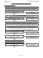
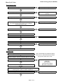
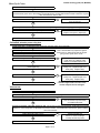
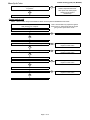
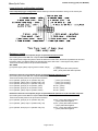
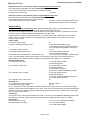
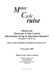
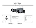
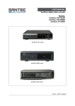
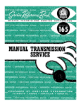
Trouble shooting guide (150, MCS590)
MotorCycle Cruise
Trouble Shooting Guide
Problem:
Undertake the following test
Perform diagnostic test on next page FIRST
1 Cruise will not engage.
NOTE: - The most common cause of cruise control malfunction is loose or dirty electrical connections.
Disconnect, clean and reconnect ALL electrical connections if the cruise control will not operate in
diagnostic mode. The usual connections are: computer plug, control switch plug, actuator plug, fuse,
'CruiseSafe' relay, speed sensor or speedometer connection, brake light switch, ground (usually battery
negative) and either tach (ignition primary) or the bike's clutch switch.
a. Check computer dip switch settings
b. Computer power test.
c. Speed sensor test if sensor installed
d. Actuator test
e. CruiseSafe actuator power relay test
f. Vacuum test
g. Actuator cable test
h. Brake wire test
i. CIU test
j. Control switch test
k. Loom continuity and voltage/resistance tests
2 Cruise control erratic, surges or
looses/gains speed.
a. Adjust gain/check dip switch settings
b. Check carburettor cable free play
c. Speed sensor test if sensor installed
d. Actuator test
e. Vacuum test
f. Actuator cable test
g. CIU test if CIU installed
3 Cruise lags or overshoots when engaged
a. Adjust gain/check dip switch settings
b. Actuator test
c. Vacuum test
d. Actuator cable test
e. CIU test if CIU installed
4 Cruise disengages
(Note: Carefully check all wiring for
intermittent connections)
a. Tach sensor test
b. Brake light switch adjustment
c. Brake wire test
d. Actuator test
5 Cruise accelerates too slow
a. Actuator test
b. Vacuum test
6 Cruise will not disengage with brake
a. Brake light switch faulty
b. Brake wire test
c. Actuator test
d. Actuator cable test
7 Carburettor will not return to idle
a. Check carburettor cable free play
b. CIU test if CIU installed
c. Actuator cable test
d. Broken throttle spring or sticking carburettors
8 Cruise will not operate at higher speeds
(above 80 kph / 50 mph)
a. Speed sensor test / gap too small
b. Too many magnets installed
c. Incorrect calibration, check dip switch settings
9 Cruise will not operate at lower speeds
(below 60 kph / 35 mph)
a. Speed sensor test / gap too large
b. Magnet/s missing
c. Incorrect calibration, check dip switch settings
Page 1 of 12
Trouble shooting guide (150, MCS590)
MotorCycle Cruise
MOTORCYCLE CRUISE TROUBLE SHOOTING TESTS
Cruise control diagnostic test
Switch ON bike's kill switch, switch ON ignition switch.
Operate front or rear brake lever.
Listen/feel for operation of relay on wiring loom near computer plug (this produces very quiet clicks).
Relay heard/felt clicking each time cruise brakes are applied
and released? (place hand on relay)
No
Go to CruiseSafe actuator relay test
Go to Brake Wire test
Yes
Operate front or rear brake lever.
Listen/feel for solenoid operation in the vacuum actuator (this produces quiet clicks).
Solenoid felt/heard clicking each time brakes are applied
and released? (place hand on actuator)
No
Go to computer power test
Go to actuator tests
Go to CruiseSafe actuator relay test
Yes
Ensure that the LED (red light) on the computer and the indicator light on the cruise control switch are visible
Place a magnet (use the spare speed sensor magnet) above or below the control switch, about half way
between the front and back of the switch, aligned with the left edge of the SET button. The green indicator
light on the switch should come ON. HOLD THE MAGNET IN THIS POSITION FOR THE NEXT STEP.
THIS PROCEDURE PLACES THE CRUISE CONTROL IN DIAGNOSTIC MODE
Switch the ignition switch OFF. Hold the magnet in position. Press and hold the SET Key.
Switch ON ignition switch. Green indicator light MUST come ON. Release SET key and remove the magnet.
Green indicator light should go out. Cruise control is now in diagnostic mode.
Press the ON-OFF switch.
Green indicator on switch ON?
No
Go to computer power test
Go to control switch test
No
Go to computer power test
Go to control switch test
No
Check brake lights
Adjust brake light switches
Go to brake wire test
Yes
Press the ON-OFF switch.
Green indicator on switch OFF?
LED on computer ON? (stays on for 10 seconds then OFF)
Yes
Press the ON-OFF switch. (Green indicator ON)
Depress brake pedal and lever
Indicator on switch turns yellow and red LED on computer
comes on with brake lights?
Yes
Page 2 of 12
Trouble shooting guide (150, MCS590)
MotorCycle Cruise
Is the cruise connected to the bikes original clutch switch
No
Skip clutch switch check
Yes
Operate the clutch lever. WARNING: - The bike may have to be in gear as often the neutral light is linked to the
same circuit as the clutch switch. The rear wheel must not touch the ground if the engine is running.
Red LED on computer (but not the control switch) comes
on with clutch operation?
Yes
Tap SET key and RES keys
Indicator and LED flashes, clicks heard or felt in actuator?
No
Test switch (no flashes)
Go to actuator test (no clicks)
Yes
Start engine
Press SET and RES keys to raise and lower engine speed. Delay can occur during these operations. CAUTION:be careful not to over rev engine. Use brakes or kill switch to switch off engine if revs are too high.
Engine speed goes up with SET key, down with RES key
No
Go to vacuum test, actuator test,
actuator cable test, CIU test
Yes
Speed sensor signal test can only be performed on the center stand on bikes that have speed signal generated
from the rear wheel, either from a sensor or from the speedometer sender unit. Engage 3rd or 4th gear and
release the clutch GENTLY. If no center stand is fitted, or speed signal comes from the front wheel, ride the bike
and observe the indicator on the cruise control switch and/or LED on computer. Increase the wheel speed to about
50~60kph (30~35mph). Observe the control switch indicator and/or computer LED.
The flash rate from the LED depends on the dip switch settings (the switches under the rubber cover on the back
end of the cruise control computer) being correct. If the DIP switch settings are correct, at 60 kph (about 37 mph)
the LED should flash approximately once per second (10 flashes over 10 seconds, between 9 and 11 seconds
is OK). If the switch settings are wrong, the flash rate will be significantly different. For example if 10 flashes
takes 8 or 12 seconds, then the DIP switch settings may be incorrect.
Indicator and LED flashing?
No
Go to speed sensor test
Yes
Speed signal OK
Diagnostic test OK. Switch ignition switch OFF to release cruise from diagnostic mode.
Computer power test
Remove 16 pin plug from computer. Turn ingnition switch ON
Check 12V on pink wire from fuse (pin 10)
No
Check fuse/power from brake circuit
No
Connect or relocate ground
Yes
Check ground (earth) on black wire (pin 8)
Yes
Computer power OK
Page 3 of 12
Trouble shooting guide (150, MCS590)
MotorCycle Cruise
Speed sensor test
Magnet/s installed?
No
Replace magnet/s
No
Reposition magnets for even
spacing
No
Reverse incorrect magnet
No
Adjust sensor gap
No
Connect wires
No
Replace sensor
Yes
Magnets spaced evenly (if more than one)?
Yes
Magnets polarity correct (all same pole outwards)?
Yes
Sensor gap correct?
Check instructions for correct gap for your installation
(Typical gap 3mm or 1/8")
Yes
Sensor wires connected and terminals tight?
Yes
Measure resistance at sensor (350~600 ohms OK)
Sensor resistance OK?
Yes
Remove computer plug from computer. Measure resistance at computer plug on pins 6 and 14
Sensor resistance OK?
No
Repair or replace loom
Yes
Sensor and sensor wires OK
Actuator test
Turn ignition switch ON, turn cruise switch ON*
Disconnect four way plug at actuator
Measure voltage on red wire on the loom (NOT the actuator)
12 volts on red wire?
*Note:- Most models only require the ignition
to be turned on, others must have the engine
going to have power to the cruise.
No
Yes
Use clip lead or piece of hook up wire to reconnect red wire to
actuator
Bad actuator power relay
Bad loom
Bad computer
Test relay/loom/computer
Bad cruise control switch
Use clip leads or piece of hook up wire. Tap brown, green and yellow
wires to ground. Valves in actuator should click.
Valve clicking heard or felt (Place hand on actuator)?
Yes
Page 4 of 12
No
Replace actuator valve pack
Trouble shooting guide (150, MCS590)
MotorCycle Cruise
Start engine
NOTE: - use caution with this test. Engine revs will increase RAPIDLY when yellow wire is grounded.
Ground brown & green wires. Momentarily ground yellow wire. Engine RPM should increase until brown or green
wire removed, then return to idle.
RPM rises then falls to idle?
No
Perform actuator cable test
then vacuum test
Yes
Repeat above, but hold rpm at about 2000-3000 by holding brown & green, tapping yellow to ground.
RPM hold reasonably steady?
No
Increase or decrease in RPM,
Replace valve pack or diaphragm.
Yes
Actuator OK
CruiseSafe actuator power relay test
Locate power relay. It is attached to the wiring loom, near the cruise control computer.
Turn ignition switch ON, turn cruise switch ON*
Operate brake lever and pedal
Relay 'clicks' with brake light operation
*Note:- Most models only require the ignition
to be turned on, others must have the engine
going to have power to the cruise.
No
Go to brake wire test
Faulty relay coil. Replace relay*
Faulty loom. Replace/repair loom
No
Go to computer power test
Faulty loom. Replace/repair loom
Faulty relay. Replace relay*
Yes
OV on both red wires to relay when brakes are applied
( brake lights ON)
Yes
12V on both red wires on relay when brakes are released
Yes
Relay OK
No
Go to computer power test
Faulty loom. Replace/repair loom
Faulty relay. Replace relay*
* Note:- Replacement relay MUST have
a resistor suppressed coil or the cruise
control computer will be damaged
Vacuum test
Engine at idle, remove hose from actuator.
Engine should run rough, vacuum pulses should be felt by finger over the end of the hose
Vacuum detected and/or engine runs rough?
No
Yes
Kinked/pinched/blocked vacuum
hose or vacuum stop valve faulty
or installed backwards
Disconnect actuator cable from throttle or CIU. Disconnect four way plug at actuator. Start engine, turn cruise
switch on. Use hook up wire or clip leads to reconnect red wire. Ground all three other (brown, green & yellow)
wires from actuator.
Cable retracts in under 4 secs?
No
Yes
Vacuum OK
Page 5 of 12
Perform actuator test
Check for vacuum blockage
or faulty vacuum stop valve
Trouble shooting guide (150, MCS590)
MotorCycle Cruise
Actuator Cable test
Disconnect cable from throttle or CIU. Inspect cable for kinks, crushing, or bends under 3" radius.
Cable kinked or bent?
Yes
Replace actuator cable
No
Replace actuator cable
No
Check that cable slides smoothly with no binding?
Yes
Cable OK
Brake wire test
Ensure brake light works
Remove 16 pin plug at computer. Measure voltage at orange & grey brake sensor wires at pins 3 and 4
Orange 12 volts always?
No
Check connection of brake wires
Check brake light fuse
No
Check connection of brake wires
Check brake light fuse
Yes
Grey at 12 volts only when brakes on?
Yes
Brake sensor wires OK
CIU test
(Only models that don't have the actuator cable connected directly to the carburettors)
Check movement of hand throttle produces corresponding movement of carburettor throttles
Carburettors moving?
No
Check for broken cables or CIU for
correct assembly or broken
internal components/incorrect
cable spool hole marking (see
drawing on last page of instruc's)
Yes
Back off adjustment of throttle cables
to ensure free play at twist grip. Lube
cables with light oil and twist grip with
engine oil. It may be necessary to lube
the carburettor throttle spindle. Use a
silicone or Teflon spray.
Yes
Check operation of throttle, heavy or stiff
Is throttle binding at all during operation?
No
Back off adjusters on cables from twist grip to give
maximum free play
Check the free play in the carburettor cable (cable from CIU to carburettors) by pulling outer cable out of the
adjuster until the carburettors start to open
Free play between 1mm and 3mm?
No
Yes
Loosen retaining screw on actuator cable at the CIU
Gently pull out the actuator cable
Page 6 of 12
Adjust carburettor cable free play
Trouble shooting guide (150, MCS590)
MotorCycle Cruise
Small amount of free play (2~4mm), then carburettors start
to operate?
No
Yes
Check CIU for correct assembly/
broken components/incorrect
cable spool hole markings(see
drawing on last page of
instructions)
CIU OK
Control switch test#
# Note: - refer to switch voltage and resistance values at end of guide for detailed check of switch
Check kill switch ON. Turn ignition switch ON*. Observe
LED (red light) on computer.
*Note:- Most models only require the ignition
to be turned on, others must have the engine
going to have power to the cruise.
Turn cruise control power switch OFF
LED on computer ON, indicator on switch OFF
No
Check computer power
No
Go to voltage/resistance checks
Replace control switch
No
Go to voltage/resistance checks
Replace control switch
No
Go to voltage/resistance checks
Replace control switch
No
Go to voltage/resistance checks
Replace control switch
Yes
Turn cruise control power switch ON
LED on computer OFF, indicator on switch green.
Yes
Back lighting in switch ON (hard to see in bright conditions)
Yes
Set key held down
LED on computer ON
Yes
Resume key held down
LED on computer ON
Yes
Control switch OK
Page 7 of 12
Trouble shooting guide (150, MCS590)
MotorCycle Cruise
Tach sensor test
# Note: - This test can be used if the cruise control disengages at random without any input from the rider.
Refer to the installation instructions for the cruise control. Find the section, 'Installing the wiring loom' which
will be in Section 7 of the manual. Find the reference to 'Connecting the tach or ignition sensor'.
In this section you will be shown how to connect the tach sensor wire to the bike's ignition coil or tachometer
signal.
Disconnect the yellow wire on the cruise control loom from the bike's ignition coil or tachometer.
Reconnect the bike's original coil wire or tachometer wire to its original connection. Tape up the yellow
cruise control wire to prevent electrical short circuits.
Test ride the bike to check if the cruise control still disengages randomly.
WARNING: - The clutch disengage function on the cruise control will not work. DO NOT OPERATE
THE CLUTCH WHILE THE CRUISE CONTROL IS ENGAGED.
Does the cruise operate normally without disengaging at
random?
No
Contact MotorCycle Setup for possible
solutions
Yes
Reconnect tach sensor wire
Return to other tests for cruise disengage
Computer DIP switch settings
Refer to the computer installation section of the Installation Manual (Section 7), Road Test & Adjustments in the
Installation Manual (Section 9) or the section on adjusing the gain in the Operation & User manual. These sections
will also give you the correct original setting for your bike.
+
0
-1
SW2
2 3 4 5
SW1
Page 8 of 12
Trouble shooting guide (150, MCS590)
MotorCycle Cruise
5
2
85
1
3
30 86
87
Wiring diagram
Page 9 of 12
Trouble shooting guide (150, MCS590)
MotorCycle Cruise
Loom wiring pin configuration and tests
Loom computer plug pin configuration Check continuity of all wires and that the wires go to the correct pins.
Resistance checks
Resistance values at loom computer plug for suspected Control Switch fault
(check with ignition switch OFF and computer UNPLUGGED from loom)
Use a speed sensor magnet and place it above OR below the control switch, about half way between the front and
back of the switch, and aligned with the left (outside) edge of the SET button. Hold magnet in this position.
Touch the ohmmeter probes to the pin numbers indicated
SET & RES
Pin 2 (switch signal, yellow) & pin 5 (power to switch, orange)
∞ Ω(ohms)
"
0 Ω(ohms) when SET button pressed
"
1500 Ω(ohms) when RES button pressed
Resistance values at loom computer plug for suspected Actuator (throttle servo) fault
(check with ignition switch OFF and computer UNPLUGGED from loom)
Touch the ohmmeter probes to the pin numbers indicated
Pin 12 (actuator, green) & pin 11 (actuator relay, red)
∞ Ω(ohms) (no continuity)
Pin 13 (actuator, yellow) & pin 11 (actuator relay, red)
∞ Ω(ohms) (no continuity)
Pin 15 (actuator, brown) & pin 11 (actuator relay, red)
∞ Ω(ohms) (no continuity)
Pin 12 (actuator, green) & pin 13 (actuator, yellow)
80~100 Ω(ohms)
Pin 12 (actuator, green) & pin 15 (actuator, brown)
80~100 Ω(ohms)
Pin 13 (actuator, yellow) & pin 15 (actuator, brown)
80~100 Ω(ohms)
Resistance values at loom computer plug for suspected Actuator (throttle servo) & CruiseSafe relay fault
(check with ignition switch ON and computer UNPLUGGED from loom)
Touch the ohmmeter probes to the pin numbers indicated
Pin 12 (actuator, green) & pin 11 (actuator relay, red)
40~50 Ω(ohms) with brakes released
"
∞ Ω(ohms) with brakes applied
Pin 13 (actuator, yellow) & pin 11 (actuator relay, red)
40~50 Ω(ohms) with brakes released
"
∞ Ω(ohms) with brakes applied
Pin 15 (actuator, brown) & pin 11 (actuator relay, red)
40~50 Ω(ohms) with brakes released
"
∞ Ω(ohms) with brakes applied
Page 10 of 12
Trouble shooting guide (150, MCS590)
MotorCycle Cruise
Resistance values at loom computer plug for suspected ground connection fault
(check with ignition switch OFF and computer UNPLUGGED from loom)
Touch the ohmmeter probes to the pin numbers or locations indicated
Pin 8 (ground) & vehicle frame
0 Ω(ohms)
Resistance values at loom computer plug for suspected Speed Sensor fault
(check with ignition switch OFF and computer UNPLUGGED from loom)
Touch the ohmmeter probes to the pin numbers indicated
Pin 14 (sensor active) & pin 6 (sensor sheild)
350~600 Ω(ohms) if using supplied speed sensor
Unknown if units taps into motor cycle speedo.
Voltage checks
Voltage values at loom computer plug (check with ignition ON (engine running on some models) and cruise
control in diagnostic mode. See the next line to put cruise control in diagnostic mode.
Use a speed sensor magnet and place it above OR below the control switch, about half way between the front and
back of the switch, and aligned with the left (outside) edge of the SET button.
Hold the magnet in position. Press and hold SET key. Turn ignition switch ON. Release SET key and remove
magnet. Place +ve probe in the back of the computer plug to measure voltages and -ve probe to motor cycle
frame or on pin 8, ground.
Control switch
Pin 1 (switch ground, green)
0V
Pin 2 (SET & RES switch signal, yellow)
0V (ON-OFF switch MUST be ON)
"
11~14V with SET pressed (ON-OFF switch ON)
"
3~5V with RES pressed (ON-OFF switch ON)
Pin 5 (power to switch, orange)
11~14V
Pin 9 (ON-OFF switch signal, brown)
11~14V with ON-OFF switch OFF
"
3~6V with ON-OFF switch ON *
Pin 9 Clutch and/or neutral sensor (on some models only)
11~14V when clutch operated or neutral selected
* Note: - On some bikes if clutch and neutral switch are connected to cruise control, the bike will have to be in
gear to read the 3~6V. When the clutch is operated or neutral selected pin 9 will be at 11~14V always.
Actuator (throttle servo)
Pin 11 (actuator power, red)
10~13V with brakes released
"
0V with brakes applied
Pin 12 (actuator dump, green)
10~13V with brakes released
"
0V with brakes applied
"
0~1V with SET key pressed
"
0V with 10~13V pulses with RES key pressed
Pin 13 (actuator vacuum, yellow)
10~13V with brakes released
"
0V with brakes applied
"
10~13V with 0V pulses with SET key pressed
"
10~13V with RES key pressed
Pin 15 (actuator safety dump, brown)
0V
Speed Sensor
Pin 14 (speed sensor active signal, blue)
See note 1 below
Pin 6 (speed sensor ground, black)
0~0.1V
Note 1: - Speed sensor signal with MCS 027 passive coil speed sensor will be about 0.1V pulse when the magnet
passes the wheel. Meter needle will flicker on 0.5v range. If the cruise is connected to the motorcycles speedometer
sender is may produce a similar signal (some BMW use this type of speedo sender) or it will be a 0V to 4~8V pulse
that occures with wheel rotation.
Tach Sensor
Pin 16 (Tach sensor, yellow) DO NOT CHECK VOLTAGE. THIS IS AN TACHO (IGNITION PRIMARY) INPUT AND
MAY BE HIGH VOLTAGE. Ignition signal may be checked with an oscilloscope if tach input is not working.
Brake Sensor
Pin 3 (brake power, orange)
11~14V, max 1V drop with brakes applied
Pin 4 (brake light sensor, grey)
0~1V with brakes released
"
11~14V with brakes applied
Page 11 of 12
Trouble shooting guide (150, MCS590)
MotorCycle Cruise
Power
Pin 10 (12V power in , pink)
Ground
Pin 7 (diode ground, black)
Pin 8 (ground, black)
11~14V
0V
0V
Page 12 of 12