1
User Manual
FlexDSL MiniFlex
MINIFLEX DEVICES
TECHNICAL DESCRIPTION AND OPERATIONS MANUAL
Version
Document name
Revision
1.14
UM_Flexdsl-Miniflex_V1-14
24. June 2014
1
MiniFlex
User Manual
MiniFlex
© Copyright 2014 by FlexDSL Telecommunications AG. The content of this publication may not
be reproduced in any part or as a whole, transcribed, stored in a retrieval system, translated into
any language, or transmitted in any form or by any means, electronic, mechanical, magnetic,
optical, chemical, photocopying, manual, or otherwise, without the prior written permission of
FlexDSL Telecommunications AG. Published by FlexDSL Telecommunications AG. All rights
reserved.
2
User Manual
MiniFlex
VERSION CONTROL ................................................................................................................ 9
SAFETY REGULATIONS .......................................................................................................... 9
EU DIRECTIVE 2002/96/EC AND EN50419 .............................................................................. 9
1
SELECTION GUIDE ......................................................................................................... 10
2
PRECAUTION .................................................................................................................. 12
3
TECHNICAL DESCRIPTION ............................................................................................ 13
3.1
General Information about FlexDSL MiniFlex ............................................................. 13
3.2
Description of MiniFlex Devices ................................................................................. 14
3.2.1
Subrack with Integrated Switch ........................................................................... 15
3.2.2
Power Supplies for the Subrack .......................................................................... 16
3.2.3
MiniRack ............................................................................................................. 17
3.2.4
SHDSL Line Card ............................................................................................... 19
3.2.4.1
Line Card SHDSL Interface.......................................................................... 20
3.2.4.1.1 Master/Slave ............................................................................................ 20
3.2.4.1.2 Multipair Mode.......................................................................................... 20
3.2.4.1.3 Automatic Link Configuration.................................................................... 21
3.2.4.1.4 SHDSL Test Loop, Analogue Loop Back .................................................. 21
3.2.4.1.5 SHDSL Performance Monitoring (Noise Margin, G.826) ........................... 22
3.2.4.2
Line Card Ethernet Interface ........................................................................ 23
3.2.4.3
Line Card MAC Filter ................................................................................... 25
3.2.4.3.1 Line Card MAC Filter Rules ...................................................................... 26
3.2.4.4
Line Card Rapid Spanning Tree Protocol ..................................................... 26
3.2.4.5
Line Card Alarm and LED Description.......................................................... 28
3.2.4.6
Line Card Management with Local Craft Terminal and Ethernet .................. 29
3.2.4.6.1 Telnet (Ethernet Interface)........................................................................ 29
3.2.4.6.2 WEB (Ethernet Interface).......................................................................... 30
3.2.4.6.3 SNMP (Ethernet Interface) ....................................................................... 32
3.2.4.6.4 SSH.......................................................................................................... 34
3.2.4.6.5 RADIUS.................................................................................................... 34
3.2.4.6.5.1 RADIUS SERVER SETUP WITH DEFINED VENDOR SPECIFIC
ATTRIBUTES............................................................................................................. 35
3.2.4.6.5.2 SIMPLIFIED RADIUS SERVER SETUP................................................. 36
3.2.4.6.5.3 CONFIGURING USER ACCESS RIGHTS ............................................. 37
3.2.5
SHDSL DINrail Modem ....................................................................................... 39
3.2.6
Single or Dual FOM Line Card ............................................................................ 39
3.2.6.1
Line Card SFP and Ethernet Interface ......................................................... 40
3.2.6.2
Line Card Alarm and LED Description.......................................................... 40
3.2.7
Single or Dual FOM DINrail Modem .................................................................... 41
3.2.8
POE Line Card.................................................................................................... 42
3.2.8.1
Line Card LED Description........................................................................... 44
3.2.9
POE DINrail Unit ................................................................................................. 45
3.2.10 Managed Switch Line Card ................................................................................. 45
3.2.10.1 Line Card LED Description........................................................................... 46
3.2.11 Managed Switch DINrail Unit .............................................................................. 46
3.2.12 Serial RS-232/422/485 Interface Line Card......................................................... 46
3.2.12.1 Line Card SFP and Ethernet Interface ......................................................... 47
3.2.12.2 Line Card Serial RS-232/422/485 Interface.................................................. 47
3.2.12.3 Line Card Alarm and LED Description.......................................................... 47
3.2.13 Serial RS-232/422/485 Interface DINrail Modem................................................. 48
3.2.14 Serial RS-232 Line Card ..................................................................................... 48
3.2.14.1 Line Card Serial Interface ............................................................................ 49
3.2.14.2 Line Card LED Description........................................................................... 49
3.2.15 Serial RS-232 DINrail Unit .................................................................................. 50
3.2.16 Default IP Address .............................................................................................. 51
3
User Manual
3.2.16.1
3.2.16.2
3.2.16.3
3.2.16.4
4
MiniFlex
DINrail Unit .................................................................................................. 51
MiniRack ...................................................................................................... 51
Subrack with Integrated Switch .................................................................... 51
Line Card ..................................................................................................... 52
PROGRAMMING GUIDE MINIFLEX SWITCH ................................................................. 53
4.1
MiniFlex Command Line Interface.............................................................................. 53
4.2
Getting Help............................................................................................................... 55
4.3
Read-Only and Privileged modes of operation ........................................................... 55
4.3.1
Entering to and exiting from privileged mode ...................................................... 55
4.4
User Management ..................................................................................................... 56
4.4.1
Creating a user ................................................................................................... 56
4.4.2
Configuring user rights ........................................................................................ 56
4.4.3
Changing a password for privileged mode .......................................................... 56
4.4.4
Changing a login password for a user ................................................................. 56
4.4.5
Getting a list of users .......................................................................................... 56
4.4.6
Deleting a user.................................................................................................... 56
4.5
Setting up a System Date and Time........................................................................... 56
4.5.1
An automatic System Date and Time Settings .................................................... 56
4.5.2
Manual System Date and Time Settings ............................................................. 57
4.5.3
System Date and Time Displaying ...................................................................... 57
4.6
Understanding your environment ............................................................................... 57
4.6.1
Checking your access rights ............................................................................... 58
4.6.2
Checking who else is connected to a system ...................................................... 58
4.6.3
Dropping a session of another user..................................................................... 58
4.6.4
Checking a node you connected to ..................................................................... 58
4.6.5
Checking a contact person.................................................................................. 58
4.6.6
Check software version....................................................................................... 58
4.6.7
Setting an IP address of a switch ........................................................................ 59
4.6.8
Deleting a IP address of a switch ........................................................................ 59
4.6.9
Check an IP address and switching configuration of a node................................ 59
4.6.10 List interface status ............................................................................................. 59
4.6.11 Display a forwarding database (FDB).................................................................. 60
4.6.12 Get a technical support. ...................................................................................... 60
4.7
Saving and restoring a system configuration.............................................................. 60
4.7.1
Saving a current configuration as a startup configuration .................................... 61
4.7.2
Saving current configuration as a backup configuration ...................................... 61
4.7.3
Restoring a backup configuration........................................................................ 61
4.7.4
Restoring a factory defaults................................................................................. 62
4.7.5
Rebooting a switch.............................................................................................. 62
4.7.6
Viewing a configuration and storing it on a PC .................................................... 62
4.7.6.1
Viewing a running configuration ................................................................... 62
4.7.6.2
Viewing a startup configuration .................................................................... 62
4.7.6.3
Viewing a backup configuration.................................................................... 63
4.7.6.4
Storing a configuration with Hyper Terminal................................................. 63
4.7.6.5
Storing a configuration with PuTTY .............................................................. 64
4.7.7
Download a configuration to a switch .................................................................. 66
4.8
Working with ports ..................................................................................................... 66
4.9
Working with VLAN .................................................................................................... 70
4.9.1
Creating a Port-Based VLAN .............................................................................. 70
4.9.2
Deleting a VLAN ................................................................................................. 72
4.9.3
Creating a TAG-based VLAN .............................................................................. 72
4.9.4
Creating a Port and TAG-based VLAN................................................................ 73
4.9.5
Creating an IP Subnet-based VLAN.................................................................... 75
4.9.6
Creating a MAC-Based VLAN ............................................................................. 76
4.9.7
A list of commands related with plain VLAN ........................................................ 77
4.10 Forwarding Database................................................................................................. 78
4.11 Rapid Spanning Tree ................................................................................................. 79
4.12 Link Aggregation Control Protocol.............................................................................. 83
4.13 Trunks........................................................................................................................ 83
4.14 Switch Ethernet Ring Protection................................................................................. 84
4.15 IGMP Snooping.......................................................................................................... 86
4.16 Multicast VLAN registration ........................................................................................ 89
4
User Manual
MiniFlex
4.17 Multiple Spanning Tree Protocol ................................................................................ 91
4.18 Q-in-Q and VLAN Translation .................................................................................... 92
4.19 Jumbo Frames Support.............................................................................................. 93
4.20 Radius........................................................................................................................ 93
4.20.1 Configuring Radius Attributes.............................................................................. 94
4.20.2 Configuring Radius Authentication Service ......................................................... 95
4.20.3 Configure Radius Accounting Service ................................................................. 96
4.20.4 Configuring ISP-Domain ..................................................................................... 96
4.21 SNMP ........................................................................................................................ 97
4.22 Access control............................................................................................................ 98
4.23 802.1x Access control .............................................................................................. 100
4.23.1 Configuring Protocol parameters....................................................................... 101
4.23.2 Configuring 802.1x Control for the port ............................................................. 102
4.23.3 Setting the Re-authentication Mechanism ......................................................... 103
4.23.4 Configuring Keep-alive Mechanism................................................................... 103
4.23.5 Forcing users to Log out from the Authentication Status ................................... 104
4.23.6 Configuring Session Timeout Mechanism ......................................................... 104
4.24 Configuring DHCP Relay, DHCP Option 82 and DHCP Snooping............................ 104
4.24.1 DHCP Relay related commands ....................................................................... 106
4.24.2 DHCP Snooping related commands.................................................................. 107
4.24.3 Secure Forwarding related commands.............................................................. 107
4.25 Quality of Service (QoS) .......................................................................................... 108
4.25.1 Queues ............................................................................................................. 108
4.25.2 Traffic to queues allocation mechanism ............................................................ 109
4.25.3 Configuring QoS ............................................................................................... 110
4.26 Configuring GVRP ................................................................................................... 111
4.27 Anti DoS protection .................................................................................................. 112
5
PROGRAMMING GUIDE LINE CARDS & DINRAIL ...................................................... 113
5.1
Command Structure SHDSL & Serial....................................................................... 113
5.2
Command Structure FOM, POE & Switch ................................................................ 114
5.3
SHDSL, Serial, FOM, POE & Switch Line Card & DINrail Software.......................... 115
5.4
Configuration and Application Storage ..................................................................... 116
5.5
Groups of Commands Requiring Confirmation ......................................................... 117
5.6
Command Syntax .................................................................................................... 118
5.7
Commands .............................................................................................................. 119
5.7.1
Main Menu ........................................................................................................ 119
5.7.1.1
System Invitation........................................................................................ 119
5.7.2
General Commands.......................................................................................... 120
5.7.2.1
<H> Command .......................................................................................... 120
5.7.2.2
<APPLY [ALL/GROUP]> Command........................................................... 120
5.7.2.3
<CONNECT N:1..13/R> Command............................................................ 120
5.7.2.4
<LINK [SN/00/FE]> Command ................................................................... 120
5.7.2.5
<LINKCLEAR> Command ......................................................................... 120
5.7.3
Performance Management Menu ...................................................................... 121
5.7.3.1
<H> Command .......................................................................................... 121
5.7.3.2
<G826> Command .................................................................................... 121
5.7.3.3
<ALLG826 N> Command........................................................................... 122
5.7.3.4
<RESETG826> Command......................................................................... 122
5.7.3.5
<RESETALLG826 N> Command............................................................... 122
5.7.3.6
<NETSTAT [LAN/WAN]> Command .......................................................... 122
5.7.3.7
<NETERR [LAN/WAN]> Command............................................................ 123
5.7.3.8
<RESETNETSTAT> Command ................................................................. 124
5.7.3.9
<LINKSTAT> Command ............................................................................ 124
5.7.3.10 <LINKALARM> Command ......................................................................... 124
5.7.3.11 <ALARMLOG [N]> Command .................................................................... 124
5.7.3.12 <LINKDIAG> Command............................................................................. 125
5.7.3.13 <M> Command .......................................................................................... 125
5.7.4
Fault and Maintenance Management Menu ...................................................... 126
5.7.4.1
<H> Command .......................................................................................... 126
5.7.4.2
<NM> & <LINKNM> Command.................................................................. 127
5.7.4.3
<STATUS> Command ............................................................................... 127
5.7.4.4
<STATUS ETH> Command ....................................................................... 128
5
User Manual
MiniFlex
5.7.4.5
<STATUS SFP> Command ....................................................................... 128
5.7.4.6
<STATUS EXT> Command ....................................................................... 128
5.7.4.7
<STATUS RADIUS> Command................................................................. 128
5.7.4.8
<LOOP2 [N:A/R] [ON/OFF]> Command..................................................... 129
5.7.4.9
<ALARM> Command................................................................................. 129
5.7.4.10 <AСO [GROUP ON/OFF])> Command ...................................................... 130
5.7.4.11 <MACTABLE> Command .......................................................................... 131
5.7.4.12 <STARTAL [N]> Command........................................................................ 131
5.7.4.13 <RESTART [N=1..2]> Command ............................................................... 131
5.7.4.14 <RESET> Command ................................................................................. 131
5.7.4.15 <CONFIRM> Command............................................................................. 132
5.7.4.16 <BACKUP> Command............................................................................... 132
5.7.4.17 <RESTORE> Command ............................................................................ 132
5.7.4.18 <DIFF N/R/S/B N/R/S/B> Command.......................................................... 132
5.7.4.19 <DUMP N/R/S/B> Command ..................................................................... 132
5.7.4.20 <LOAD> Command ................................................................................... 133
5.7.4.21 <TLM> Command ...................................................................................... 133
5.7.4.22 <TLM S [N:[Rnn-Rkk]] [ABC]> Command .................................................. 134
5.7.4.23 <LOG> and [LOG C] Command................................................................. 135
5.7.4.24 <SOFTUPDATE> Command ..................................................................... 135
5.7.4.25 <TFTP [CMD] [ARG1][ARG2]> Command ................................................. 135
5.7.4.26 <SOFTCONFIRM> Command ................................................................... 136
5.7.4.27 <SOFTINFO> Command ........................................................................... 136
5.7.4.28 <PING x.x.x.x> Command ......................................................................... 136
5.7.4.29 <MODEMVIEW> Command....................................................................... 136
5.7.4.30 <SD SNAPSHOT> Command.................................................................... 136
5.7.4.31 <SD DIR> Command ................................................................................. 136
5.7.4.32 <SD DEL [NAME]> Command ................................................................... 136
5.7.4.33 <SD SAVE [N=0..9]> Command ................................................................ 137
5.7.4.34 <SD LOAD [N=0..9]> Command ................................................................ 137
5.7.4.35 <SD BOOT [ON/OFF]> Command............................................................. 137
5.7.4.36 <SD STATUS> Command ......................................................................... 137
5.7.5
Configuration Management Menu ..................................................................... 138
5.7.5.1
<H> Command .......................................................................................... 138
5.7.5.2
<SECURE ON/OFF> Command ................................................................ 139
5.7.5.3
<USERS> Command................................................................................. 139
5.7.5.4
<USER> Command ................................................................................... 139
5.7.5.5
<PASSWORD {users}> Command............................................................. 141
5.7.5.6
<CONFIG [N/R/S/B] > Command............................................................... 142
5.7.5.7
<MASTER ON/OFF [N = 1..2]> Command................................................. 143
5.7.5.8
<AUTO ON/OFF> Command ..................................................................... 143
5.7.5.9
<EXT ON/OFF [N = 1..2]> Command ........................................................ 143
5.7.5.10 <BASERATE K/AUTO [N=1..2]> Command............................................... 143
5.7.5.11 <PAM [16/32] [N]> or <PAM [4-128] [N]> Command.................................. 144
5.7.5.12 <PAYLOAD list/NONE [N=1..2]> Command............................................... 144
5.7.5.13 <ANNEX A/B/AB [N=1..2]> Command ....................................................... 144
5.7.5.14 <SETCLOCK list [N=1..2]> Command ....................................................... 144
5.7.5.15 <MULTIPAIR [2/OFF]> Command ............................................................. 144
5.7.5.16 <RESERVE [list]>, <RESERVE [list] [list]> Command................................ 144
5.7.5.17 <ID string> Command................................................................................ 145
5.7.5.18 <DEFAULT [0-4]> Command ..................................................................... 145
5.7.5.19 <DEFAULT EVERYTHING> Command ..................................................... 145
5.7.5.20 <DEFAULT DESC> Command .................................................................. 145
5.7.5.21 <POECONFIG> Command........................................................................ 145
5.7.5.22 <POEPORT [ON/OFF] [N]> Command ...................................................... 145
5.7.5.23 <SERNUM> Command.............................................................................. 145
5.7.5.24 <GSCOMPAT ON/OFF> Command........................................................... 145
5.7.5.25 <NMTHR> Command ................................................................................ 146
5.7.5.26 <LATHR> Command ................................................................................. 146
5.7.5.27 <PTMP [ADD/DEL] [IF]> Command ........................................................... 146
5.7.5.28 <PTMP SHOW> Command ....................................................................... 146
5.7.5.29 <MODE N> Command ............................................................................... 146
5.7.5.30 <RSIP> Command..................................................................................... 146
6
User Manual
5.7.5.31
5.7.5.32
5.7.5.33
5.7.5.34
5.7.5.35
5.7.5.36
5.7.5.37
5.7.5.38
5.7.5.39
5.7.5.40
5.7.5.41
5.7.5.42
5.7.5.43
5.7.5.44
5.7.5.45
5.7.5.46
5.7.5.47
5.7.5.48
5.7.5.49
5.7.5.50
5.7.5.51
5.7.5.52
5.7.5.53
5.7.5.54
5.7.5.55
5.7.5.56
5.7.5.57
5.7.5.58
5.7.5.59
5.7.5.60
5.7.5.61
5.7.5.62
5.7.5.63
5.7.5.64
5.7.5.65
5.7.5.66
5.7.5.67
5.7.5.68
5.7.5.69
5.7.5.70
5.7.5.71
5.7.5.72
5.7.5.73
5.7.5.74
5.7.5.75
5.7.5.76
5.7.5.77
5.7.5.78
5.7.5.79
5.7.5.80
5.7.5.81
5.7.5.82
5.7.5.83
5.7.5.84
5.7.5.85
5.7.5.86
5.7.5.87
5.7.5.88
5.7.5.89
5.7.5.90
5.7.5.91
5.7.5.92
5.7.5.93
MiniFlex
<LICENSE> Command .............................................................................. 149
<LICENSE ADD> Command...................................................................... 149
<RSRATE [N]> Command ......................................................................... 149
<RSFORMAT [Format]> Command ........................................................... 149
<RSDUPLEX [F/H] Command ................................................................... 149
<RS [232/485] Command........................................................................... 149
<RS TERM [ON/OFF] Command ............................................................... 149
<NET> Command ...................................................................................... 149
<H> Command .......................................................................................... 149
<NETCONFIG [N/R/S/B]> Command......................................................... 151
<COSCONFIG [N/R/S/B]> Command ........................................................ 152
<RSTP DEFAULT> Command................................................................... 153
<RSTP [A..E] [ON/OFF]> Command.......................................................... 154
<RSTP [A..E] PRIO [value]> Command ..................................................... 154
<RSTP [A..E] VLAN [1..8]> Command ....................................................... 154
<RSTP [A..E] HELLO [2..10]> Command................................................... 154
<RSTP [IFACE] PRIO [0..240]> Command ................................................ 154
<RSTP [IFACE] PCOST [AUTO/1..200000000]> Command...................... 154
<RSTP [IFACE] EDGE [ON/OFF]> Command ........................................... 154
<RSTP CONF> Command......................................................................... 155
<RSTP STATE> Command ....................................................................... 155
<PBVLAN [IF] [A..E]> Command ............................................................... 156
<MODE [IF] [ACC/TRUNK/MIX]> Command.............................................. 157
<VLAN [IF] [1..8]> Command ..................................................................... 157
<QOS [IF] [0..7]> Command ...................................................................... 158
<ALLOW [IF] [VLAN list]> Command ......................................................... 158
<VID [1-8] ID> Command........................................................................... 158
<MACLIST SHOW> Command.................................................................. 158
<MACLIST [IF] ADD [MAC]> Command .................................................... 159
<MACLIST [IF] DEL [MAC/N]> Command.................................................. 159
<MACFILTER [LAN1-5] [ON/OFF]> Command.......................................... 159
<MACRULE [LAN1-5] [RULE]> Command................................................. 160
<SETIP X.X.X.X> Command...................................................................... 160
<NETMASK X.X.X.X> Command............................................................... 160
<GATEWAY X.X.X.X> Command .............................................................. 161
<MTU> Command ..................................................................................... 161
<WANIDLE [1/7E]> Command................................................................... 161
<ETHSD [10H/10F/100H/100F/AUTO/OFF] [N=1..2]> Command .............. 161
<FC [ON/OFF] [N1-4]> Command ............................................................. 161
<IRATE [speed/OFF] [N1-4]> Command ................................................... 161
<ERATE [speed/OFF]> Command............................................................. 162
<CRATE [speed] [CoS] [WAN]> Command................................................ 162
<COS [QOS/VLAN] [N] [0..3/OFF]> Command .......................................... 163
<SNMPACL> Command ............................................................................ 163
<SNMP [V1|V2C|V3] [ON|OFF]> Command .............................................. 163
<TRAPIP [1/2] [IP/OFF]> Command .......................................................... 163
<TRAP [1/2] [V1/V2C]> Command............................................................. 163
<TRAP [1/2] V3 [RO/RW]> Command ....................................................... 163
<COMMUNITY> Command ....................................................................... 164
<SNMPSET [ON/OFF]> Command............................................................ 164
<SNMP [RO|RW] NAME> Command......................................................... 164
<SNMP [RO|RW] AUTH [MODE]> Command............................................ 164
<SNMP [RO|RW] PRIV [MODE]> Command ............................................. 164
<SYSLOG [1/2] [IP/OFF]> Command ........................................................ 165
<SNTP [1/2] [IP/OFF]> Command ............................................................. 165
<SNTP TZ [+/-]HH:MM> Command ........................................................... 165
<DST> Command ...................................................................................... 165
<[SSH|TELNET|HTTP] [ON/OFF]> ............................................................ 168
<SSH PORT [N]>....................................................................................... 168
<RADIUS [1/2] SECRET>.......................................................................... 168
<RADIUS [1/2] TEST> ............................................................................... 169
<RADIUS [1/2] [IP:P/OFF]> ....................................................................... 169
<RADIUS RETRIES [0..10]>...................................................................... 169
7
User Manual
5.7.5.94
5.7.5.95
5.7.5.96
MiniFlex
<RADIUS TIMEOUT [1..5]> ....................................................................... 170
<STATUS RADIUS [N/R/S/B]> Command ................................................. 170
<NETDEFAULT> Command ...................................................................... 170
6
SOFTWARE DOWNLOAD MINIFLEX SWITCH ............................................................. 172
7
SOFTWARE DOWNLOAD SHDSL, SERIAL, FOM & SWITCH LINE CARD OR DINRAIL
173
7.1
7.2
8
SERVICE INSTRUCTIONS............................................................................................. 178
8.1
8.2
9
Software Download via USB Port (LCT) Using Xmodem Protocol............................ 173
Software Download via Ethernet (1K-Xmodem and Telnet)...................................... 177
General Requirements ............................................................................................. 178
Evaluation of the SHDSL Channel Quality and Operation Parameters..................... 178
APPENDICES................................................................................................................. 179
9.1
Quick Installation Guide for FlexDSL MiniFlex.......................................................... 179
9.1.1
Enter a FlexDSL MiniFlex ................................................................................. 179
9.1.2
Configure a FlexDSL MiniFlex........................................................................... 179
9.1.3
Checking of Correct Working ............................................................................ 182
9.1.4
Problem with FlexDSL MiniFlex ........................................................................ 182
9.2
Connector Description.............................................................................................. 183
9.2.1
Alarm Connector (ALARM)................................................................................ 183
9.2.2
DC Power Connector (DC1, DC2)..................................................................... 183
9.2.3
Gigabit Ethernet SFP Connector (P1, P2) & 100Mbps SFP FOM and Serial..... 183
9.2.4
Gigabit Ethernet Connector (P3, P4)................................................................. 184
9.2.5
10/100Mbps Ethernet Connector (P5-P12) ....................................................... 184
9.2.6
SHDSL, FOM, Switch and Serial Line Card & DINrail Ethernet Connector........ 184
9.2.7
POE Line Card Ethernet Connector .................................................................. 184
9.2.8
Serial RS-232 & RS-232/422/485 Line Card & Dinrail Serial Interface Connector
185
9.2.9
SHDSL Line Card &DINrail xDSL Connector .................................................... 185
9.2.10 DINrail Power Connector .................................................................................. 185
9.2.11 Local Craft Terminal (USB) Connector (LCT).................................................... 186
9.2.12 Connector Hoods and Cord Retaining............................................................... 186
10 TECHNICAL SPECIFICATION ....................................................................................... 188
10.1 Interfaces ................................................................................................................. 188
10.1.1 1000Base-X Gigabit Ethernet (P1, P2).............................................................. 188
10.1.2 1000Base-T, Gigabit Ethernet (P3, P4)............................................................. 188
10.1.3 10/100Base-T Ethernet (P5-P12, SHDSL, FOM, POE, Serial and Switch)........ 188
10.1.4 SHDSL Line Interface ....................................................................................... 188
10.1.5 100Base-FX Ethernet (FOM, Serial RS-232 Interface)...................................... 188
10.1.6 Serial Interface RS-232/422/485 (Serial RS-232 / RS-232/422/485 Interface) .. 189
10.1.7 Local Craft Terminal (USB) Interface ................................................................ 189
10.1.8 Alarm Interface.................................................................................................. 189
10.2 Power Supply........................................................................................................... 189
10.2.1 MiniFlex Mini DSLAM (Subrack) ....................................................................... 189
10.2.2 MiniFlex MiniRack............................................................................................. 190
10.2.3 MiniFlex DINrail................................................................................................. 190
10.3 Environment............................................................................................................. 190
10.3.1 Climatic Conditions ........................................................................................... 190
10.3.2 EMC and Safety Standards............................................................................... 190
10.4 Physical Dimensions and Weight ............................................................................. 191
10.4.1 MiniFlex Mini DSLAM (Subrack) ....................................................................... 191
10.4.2 MiniFlex MiniRack............................................................................................. 191
10.4.3 MiniFlex SHDSL, Single FOM, POE DINrail...................................................... 191
10.4.4 MiniFlex Dual FOM, Managed Switch, Serial RS-232 Interface DINrail............. 192
8
User Manual
MiniFlex
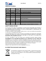
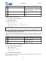
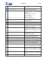
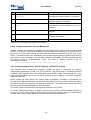
VERSION CONTROL
Manual
Version
1.0
1.1
1.2
1.3
1.4
1.5
1.6
1.7
1.8
1.9
Date
16.03.2010
28.04.2010
24.08.2010
6.09.2010
30.11.2010
03.01.2011
29.08.2011
21.10.2011
30.12.2011
03.12.2012
Software
Version
1.0.0
1.0.0
1.1.5
1.1.5
1.1.5
1.3.4
1.4.8
1.4.8
1.4.8
1.4.37
1.10
1.11
1.12
1.13
1.14
26.03.2013
02.05.2013
25.06.2013
22.10.2013
05.05.2014
1.4.38
1.4.38
1.4.38
1.5.4
1.6.6
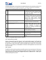
Major changes to previous version
Initial Version
DC-Power pinning changed
Small change in Safety regulations
Switch functions fully described
DSL DINRail included
RSTP in DSL Line card and DINRail added
FOM Card integrated
Software download corrected
MiniRack added
Alarm Command updated, LINKNM added, Commands
adapted, MAC Filtering
FOM2, PoE and Switch added
Jumper Settings PoE changed
Default IP address added, Port numbering, PoE Attention
SSH & RADIUS added
Table 3.15 corrected, Serial Interface Units added, SNMP&
RADIUS updated, Commands updated incl. SD-Card
SAFETY REGULATIONS
IF THE UNIT IS NOT USED IN ACCORDANCE TO REGULATIONS DESCRIBED AND DEFINED IN
THE CHAPTERS ”TECHNICAL DESCRIPTION” AND “TECHNICAL SPECIFICATIONS”, FLEXDSL
TELECOMMUNICATIONS AG REFUSES TO TAKE ANY RESPONSIBILITY. FURTHERMORE, NO
WARRANTY IS GRANTED IN SUCH CASE!
IT’S ONLY ALLOWED TO USE EXTERNAL POWER SUPPLYS THAT ARE APPROVED ACOORDING
TO THE SAFETY STANDARD IEC/EN 60950-1.
THE DISCONNECTING DEVICE FOR THE RACK IS THE MAINS PLUG AND/OR THE APPLIANCE
COUPLER. THE MAINS PLUG AND/OR THE APPLIANCE COUPLER HAS/HAVE TO BE EASILY
ACCESSIBLE AND THE MAINS PLUG HAS TO BE NEXT TO THE RACK IF THE MAINS PLUG
SERVES AS THE DISCONNECTING DEVICE.
IT’S ONLY ALLOWED TO USE THE UNITS WITH HOUSINGS SUPPLYED FROM FLEXDSL
TELECOMMUNICATIONS AG (SUBRACKS, MINIRACK, UTTX). THE RACK HAS TO BE CONNECTED
PERMANENTLY TO A RELIABLE PROTECTIVE ERTH CONDUCTOR. THE LTU UNIT AND
LINECARDS HAVE TO BE FIXED TO THE RACK PERMANENTLY WITH THE TWO PANEL SCREWS.
INCORRECT USE OF THIS DEVICE, USE IN ANY OTHER ENVIRONMENT AND/OR HOUSING THAN
PROVIDED BY FLEXDSL MIGHT LEAD TO HARMFUL CONDITIONS. FAILURE TO FOLLOW THESE
PRECAUTIONS MAY RESULT IN DEATH, SEVERE INJURY OR PROPERTY DAMAGE.
Please read this manual carefully before operating the system.
Installation of this equipment has to be done by qualified personnel only.
EU DIRECTIVE 2002/96/EC AND EN50419
Our equipment is marked with the recycling symbol. It means that at the end of
the life of the equipment you must dispose it separately at an appropriate
collection point and not place it in the normal domestic unsorted waste stream.
(European Union only)
9
Ethernet 10/100BaseT
Gigabit Eth 1000Base-T
Point-to-Point
Point-to-Multipoint
Ring Applications
Spannung Tree
Link Aggregation
VLAN, QoS
Port Security
Multicast
Remote Power Receiver
Remote Power Source
Single Pair
Dual Pair Bonding
Dual Pair Standby
Point-to-Point
Point-to-Multipoint
E1 (120Ohm)
E1 (75Ohm) optional
Ethernet Bridge
Ethernet Add/Drop
RS-232/422/485 Interface
RS-232 Interface
Remote Power Receiver
Remote Power Source
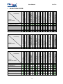
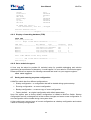
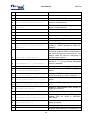
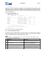
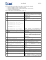
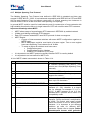
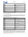
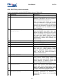
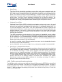
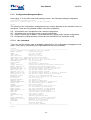
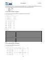
Functionality
FlexDSL
MiniFlex Models
MF-PAM-SR2L-2Eth,V1
√
√
√
√
√
√
√
√
√
MF-FOM-SRL,V1
√
√
√
MF-FOM-SR2L-2Eth,V1
√
√
√
√
√
√
√
√
MF-FOM-SR2L-SER/Eth,V1
√
√
√
√
√
√
√
√
MF-POE-SRL-2Eth,V1
√
√
√
MF-SW-SRL-8Eth,V1
√
√
√
√
MF-SER-SRL-4V24,V1
√
√
√
√
Reduandancy Possibility
MF-PS110/230, V1
√
√
MF-MR2N-SW-12Eth,V1
√
√
√
MF-MR2N,V1
√
√
√
√
√
√
√
√
√
10
√
√
√
√
√
√
√
SNMP Management
Multicast
√
SNMP Management
Port Security
√
Web Management
VLAN, QoS
√
Web Management
Link Aggregation
√
Telnet Management
Spannung Tree
√
Console Port Management
Ring Applications
√
Telnet Management
Point-to-Multipoint
√
Console Port Management
Point-to-Point
√
Console Port Management
Telnet Management
Web Management
SNMP Management
Remote Power Source
Remote Power Receiver
Gigabit Ethernet SFP
√
Gigabit Ethernet SFP
90-264 VAC, 47-63 Hz
18-72 VDC
Backside Mountable
Gigabit Eth 1000Base-T
√
Ethernet 10/100BaseT
√
Reduandancy Possibility
√
90-264 VAC, 47-63 Hz
18-72 VDC
MF-PS48, V1
Protected Housing
2U Minirack, Rail or Wall
Functionality
√
MiniFlex Subrack Module
MF-MR-RAIL-2U4S,V1
Rail Mounting
FlexDSL
MiniFlex Models
19”, 2U Subrack/Minirack
Functionality
19”, 2U Subrack/Minirack
FlexDSL
MiniFlex Line Cards
Standalone
User Manual
MiniFlex
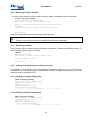
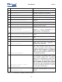
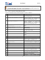
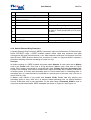
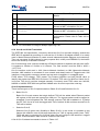
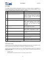
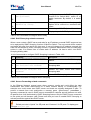
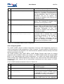
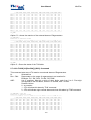
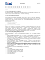
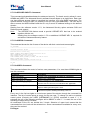
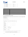
1 SELECTION GUIDE
√
√
√
√
√
√
√
√
√
√
√
√
√
√
√
√
√
√
√
√
√
√
√
√
√
√
√
√
√
√
MF-PAM-RAIL2N-2Eth-24V, V1
√
√
√
√
√
√
√
√
√
MF-PAM-RAIL2N-2Eth-230V, V1
√
√
√
√
√
√
√
√
√
MF-FOM-RAILN-Eth-24V, V1
√
√
√
√
√
MF-FOM-RAILN-Eth-230V, V1
√
√
√
√
√
MF-FOM-RAIL2N-2Eth-24V, V1
√
√
√
√
√
√
√
√
MF-FOM-RAIL2N-2Eth-230V, V1
√
√
√
√
√
√
√
√
MF-POE-RAILN-Eth-24V, V1
√
√
√
MF-SW-RAIL-4Eth-24V, V1
√
√
√
√
√
√
MF-SW-RAIL-4Eth-230V, V1
√
√
√
√
√
√
MF-FOM-RAIL2N-2V24-24V, V1
√
√
√
√
√
√
√
√
√
MF-FOM-RAIL2N-2V24-230V, V1
√
√
√
√
√
√
√
√
√
MF-FOM-RAIL2N-SER/Eth-24V,
V1
√
√
√
√
√
√
√
√
√
√
MF-FOM-RAIL2N-SER/Eth-230V,
V1
√
√
√
√
√
√
√
√
√
√
11
√
√
√
√
√
√
SNMP Management
√
Web Management
9-18 VDC
√
Telnet Management
Ethernet Add/Drop
√
Console Port Management
Ethernet Bridge
√
Remote Power Source
Point-to-Multipoint
√
Remote Power Receiver
Point-to-Point
√
90-264 VAC, 47-63 Hz
Dual Pair Standby
√
18-72 VDC
Dual Pair Bonding
√
RS-232 Interface
Single Pair
MF-PAM-RAIL2N-2Eth-12V, V1
Protected Housing
FlexDSL
MiniFlex DINrail
Rail Mounting
RS-232/422/485 Interface
MiniFlex
Standalone
Functionality
MiniFlex Subrack Module
User Manual
√
√
√
√
√
√
√
√
√
√
√
√
√
√
√
√
√
√
√
√
√
√
√
√
√
√
√
√
√
√
√
√
√
√
√
√
√
√
√
√
√
√
√
√
√
√
√
√
√
√
√
√
√
√
√
√
√
√
√
User Manual
MiniFlex
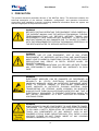
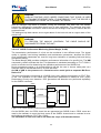
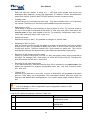
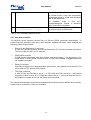
2 PRECAUTION
The present document describes devices of the MiniFlex family. The document contains the
technical description of the devices, installation, configuration, and operation instructions.
Appendices and installation manuals containing additional information about the system are
also an integral part of the present document.
WARNING
BEFORE STARTING OPERATING THE EQUIPMENT, READ CAREFULLY
THE CURRENT MANUAL AND THE INSTALLATION MANUAL. FLEXDSL
TELECOMMUNICATIONS AG REFUSES NEITHER TAKING ANY
RESPONSIBILITY NOR GRANTING ANY WARRANTY TO ANY DEVICE
MALFUNCTIONING OR ANY DAMAGES DUE TO FAILURE TO COMPLY
WITH THE REQUIREMENTS STATED IN THE MANUALS, ESPECIALLY IN
THE SECTION RELATED TO “SERVICE INSTRUCTIONS”.
WARNING
IMPROPER USE OF OUR EQUIPMENT, USE IN ANY OTHER
ENVIRONMENT OR IMPROPER INSTALLATION AND MAINTENANCE
MIGHT LEAD TO HARMFUL CONDITIONS. FAILURE TO FOLLOW THESE
PRECAUTIONS MAY RESULT IN DEATH; SEVERE INJURY OR
PROPERTY DAMAGE.
FLEXDSL TELECOMMUNICATIONS AG REFUSES NEITHER TAKING
ANY RESPONSIBILITY NOR GRANTING ANY WARRANTY IN SUCH
CASE.
WARNING
ELECTRONIC MODULES CAN BE DAMAGED OR DECREASED IN
RELIABILITY BY STATIC ELECTRICAL DISCHARGE. BEFORE
HANDLING MODULES, WEAR AN ANTISTATIC DISCHARGE WRIST
STRAP TO PREVENT DAMAGE TO ELECTRONIC COMPONENTS.
PLACE MODULES IN ANTISTATIC PACKING MATERIAL WHEN
TRANSPORTING OR STORING. WHEN WORKING ON MODULES,
ALWAYS PLACE THEM ON AN APPROVED ANTISTATIC MAT THAT IS
ELECTRICALLY GROUNDED. TO PREVENT ELECTRICAL SHOCK, DO
NOT INSTALL EQUIPMENT IN A WET LOCATION OR DURING A
LIGHTNING STORM.
WARNING
SOME MODULES CAN BE CONFIGURED TO HAVE REMOTE POWER.
THIS MEANS, THAT THERE COULD BE A HIGH VOLTAGE ACCORDING
TO EN 60950-1 SAFETY REGULATION. BE CAREFUL AND DO NOT
TOUCH ANY COMPONENTS OF ANY MODULE. ALSO IN NOT
POWERED STATUS, SOME CAPACITORS MAY STILL CARRY A HIGH
VOLTAGE. PLEASE DO NOT TOUCH INSIDE OF ANY HOUSING
(SUBRACK, MINIRACK, UTT1 OR UTT4).
12
User Manual
MiniFlex
3 TECHNICAL DESCRIPTION
3.1
General Information about FlexDSL MiniFlex
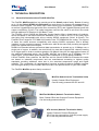
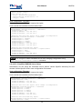
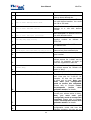
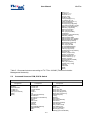
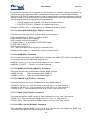
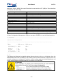
The FlexDSL MiniFlex platform is a special part of the Orion3 product family. Beside of having
up to 10 dual Orion3 SHDSL.bis Extended line cards there is a feature-rich managed layer 2
Ethernet switch included. This switch has 8 auto-sensing front accessible 10/100Base-T ports
as well as 2 gigabit Ethernet ports with fiber connectivity (SFP) and 2 gigabit Ethernet ports with
copper connectivity (RJ-45). The inside backplane connect this switch to all Orion3 line cards
through additional 10 Ethernet 10/100 Base-T ports.
The FlexDSL Orion3 SHDSL.bis Extended product family offers a broad range of products,
which are based on the latest SHDSL.bis standards (ITU-T G.991.2 & ETS TS 101 524), while
also being fully interoperable with all our existing SHDSL equipment (Orion1 & Orion2). The
FlexDSL Orion3 supports TC-PAM8/16/32 and the new TC-PAM64/128 line coding. The support
of these line codes ensures compatibility with existing SHDSL equipment, that is already
installed, in order to protect customer investments, while at the same time providing an upgrade
path to the newest DSL technologies.
SHDSL.bis Extended allows symmetrical data transmission at speeds up to 15.2Mbps over a
single pair of copper. In addition, the dual Orion3 line card also supports DSL channel bonding
for 2 copper pairs in order to achieve speeds to 30.4Mbps! Using the link aggregation feature of
the additional integrated switch, the FlexDSL MiniFlex can transmit up to 300Mbps over 20
copper pairs. This incredible speed makes Fiber installations in a lot of places needless.
Like all FlexDSL Orion products, the MiniFlex and his Orion3 SHDSL.bis Extended line cards
are based on industrial components and are manufactured according to highest quality
standards providing additional value due to the extended temperature range and higher
reliability. The combination of comprehensive functions providing maximum flexibility together
with the higher quality of the FlexDSL MiniFlex make it the perfect choice for your DSL needs.
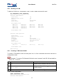
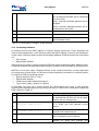
The FlexDSL MiniFlex product family consists of
MiniFlex Subrack (Line Termination Units)
Usually Central Office Equipment.
Can be locally powered with DC and AC
MiniFlex MiniRack (Network Termination Units)
Both, Central Office and Customer Premise Equipment.
Can be locally powered with DC
NTU devices (Network Termination Units)
Usually Customer Premise Equipment.
NTU’s can be powered from local DC power supply.
NTU’s can be powered remotely.
13
User Manual
MiniFlex
RR devices (Repeater, Regenerator)
Increase (double) the distance.
RR’s can be powered:
• locally with DC voltage.
• remotely.
Supported management features:
•
Local Craft Terminal (USB), Telnet, SNMP and WEB
•
Two levels of system users: administrator and user, protected with passwords
Supported operating modes:
•
Point-to-Point, Point-to-Multipoint and Ring Applications
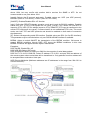
3.2
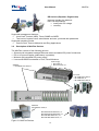
Description of MiniFlex Devices
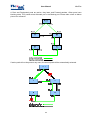
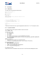
The MiniFlex consists of the following devices:
• Subrack with integrated managed Ethernet switch and alarm/DC power frontaccess
• DC or AC power supplies (redundancy is possible)
• Minirack with integrated DC power supply
• Line card SHDSLbis extended or Fiber; Dinrail Modems
Power Suppy
• MF-PS48, V1
• MF-PS110/230, V1
SubRack
• MF-MR2N-SW-12Eth,V1
Line Cards
• MF-PAM-SR2L-2Eth,V1
• MF-FOM-SRL,V1
• MF-FOM-SR2L-2Eth,V1
MiniRack
MF-MR-RAIL-2U4S,V1
MF-PAM-RAIL2N-2Eth-24V, V1
MF-PAM-RAIL2N-2Eth-230V, V1
MF-FOM-RAILN-Eth-24V, V1
MF-FOM-RAILN-Eth-230V, V1
Figure 3.1 MiniFlex Devices
14
User Manual
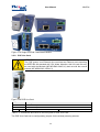
3.2.1
MiniFlex
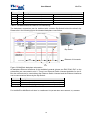
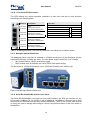
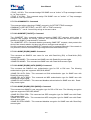
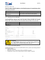
Subrack with Integrated Switch
The SubRack is designed for a 19“ rack and has a height of 2U (89mm). The is depth is180mm
without any power supply and 248mm with the power supply equiped. All connections (except
AC power!) are accessible in the front.
Beside the connection to two DC power supplies and the alarm relay outputs, there is an
intergrated layer 2 managed Ethernet switch with the following main functionalities:
Spanning Tree and Ethernet Ring
• IEEE 802.1D Spanning TreeProtocol (STP)
• IEEE 802.1w Rapid Spanning Tree Protocol (RSTP)
• IEEE 802.1s Multiple Spanning Tree Protocol (MSTP)
• Ethernet Ring Protection Mechanism, 50ms rapid ln switching and protection
• Port Mirroring, Jumbo Frames support (up to 9216 bytes)
VLAN
• 4K IEEE 802.1q VLANs, Port-based VLAN, MAC-Based VLAN, Private VLAN
• GVRP, Q-in-Q, VLAN Translation
Link Aggregation
• Static Trunk, Dynamic Trunk, IEEE 802.3ad LACP, Load Balancing
Multicast Features
• IGMP v1. v2, v3, IGMP Snooping, IGMP Groups, Multicast VLAN
Quality of Service (QoS)
• 8 Priority Queues/port, Bandwidth Control per Port
• WRR, Strict Priority, WDRR, WRR+Strict Priority
• 802.1p, Port-Based CoS, CoS based on MAC DA/SA
Access Control List
• MAC+Port Binding, VLAN+Port Binding
Port Security
• Trust Port, Port Blocking, Private VLAN, Port Powering Off
• MAC address learning limit per port, DoS check, Management IP list
Management
• Local Console Port (USB), Telnet/SSH, Web, SNMP v1 and V2c
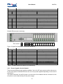
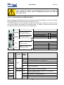
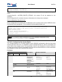
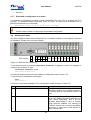
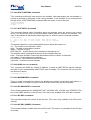
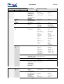
Figure 3.2 SubRack Frontplate
15
User Manual
Element
ALARM
MiniFlex
Description
ALARM Connector with Urgent/NonUrgent Alarm (6-Pin Phoenix Mini Combicom MC 1,5/6-G-3,5)
LED-1
LED-2
LED Red Urgent ALARM
LED Red NonUrgent ALARM
LED-3
LED-4
LED Green DC1 ok
LED Green DC2 ok
DC2
Power Supply Connector DC2 (3-Pin Phoenix Mini Combicom MC 1,5/3-GF-3,5)
DC1
Power Supply Connector DC1 (3-Pin Phoenix Mini Combicom MC 1,5/3-GF-3,5)
LCT
USB Connector Local Craft Terminal
P1
P2
LINK
ACT
SFP Gigabit Ethernet Uplink Port 1
SFP Gigabit Ethernet Uplink Port 2
LED Green Link corresponding Port 1-4
LED Green Activity corresponding Port 1-4
P3
P5
P4
RJ-45 Gigabit Ethernet Uplink Port 3
RJ-45 Gigabit Ethernet Uplink Port 4
P6
RJ-45 10/100Mbps Ethernet Port 5 + two LED
RJ-45 10/100Mbps Ethernet Port 6 + two LED
P7
P8
RJ-45 10/100Mbps Ethernet Port 7 + two LED
RJ-45 10/100Mbps Ethernet Port 8 + two LED
P9
P10
RJ-45 10/100Mbps Ethernet Port 9 + two LED
RJ-45 10/100Mbps Ethernet Port 10 + two LED
P11
P12
RJ-45 10/100Mbps Ethernet Port 11 + two LED RJ-45 10/100Mbps Ethernet Port 12 + two LED
Table 3.1 Connectors and LEDs on the front panel of SubRack MiniFlex.
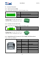
Subrack Ethernet port numbering:
Port number:
2
1
4
3
6 8 10 12
13
5 7 9 11
14 15 16 17 18 19 20 21 22
Figure 3.3 MiniFlex SubRack Ethernet Port numbering
Ethernet Port Description
P1
P2
Front: SFP Gigabit Ethernet Uplink
Front:SFP Gigabit Ethernet Uplink
P3
P4
Front:RJ-45 Gigabit Ethernet Uplink
Front: RJ-45 Gigabit Ethernet Uplink
P5
P6
Front: RJ-45 10/100Mbps Ethernet
Front: RJ-45 10/100Mbps Ethernet
P7
P8
Front: RJ-45 10/100Mbps Ethernet
Front: RJ-45 10/100Mbps Ethernet
P9
P10
Front: RJ-45 10/100Mbps Ethernet
Front: RJ-45 10/100Mbps Ethernet
P11
P12
Front: RJ-45 10/100Mbps Ethernet
Front: RJ-45 10/100Mbps Ethernet
P13
P14
Line Card 1: RJ-45 10/100Mbps Ethernet
Line Card 2: RJ-45 10/100Mbps Ethernet
P15
P16
Line Card 3: RJ-45 10/100Mbps Ethernet
Line Card 4: RJ-45 10/100Mbps Ethernet
P17
P18
Line Card 5: RJ-45 10/100Mbps Ethernet
Line Card 6: RJ-45 10/100Mbps Ethernet
P19
P20
Line Card 7: RJ-45 10/100Mbps Ethernet
Line Card 8: RJ-45 10/100Mbps Ethernet
P21
P22
Line Card 9: RJ-45 10/100Mbps Ethernet
Line Card 10: RJ-45 10/100Mbps Ethernet
Table 3.2 SubRack MiniFlex Ethernet Port Numbering.
3.2.2
Power Supplies for the Subrack
There are two different power supplies available. One is for DC input power and the other one is
for AC input power. Each MiniFlex can use one or two power supplies depending on the need of
redundancy.
The power connector for the DC power is on the front of the subrack and the connector for the
AC power is on the back directly at the power supply.
16
User Manual
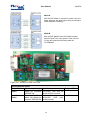
3.2.3
MiniFlex
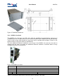
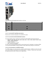
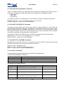
MiniRack
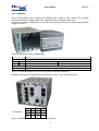
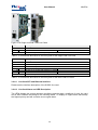
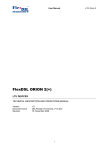
The 5 slot MiniRack has a height of 2U (88mm) and a width of only 110mm. The is depth
is181mm with power supply equiped. All connections are accessible in the front.
There are connectors available for to two DC power inputs and the alarm relay outputs (Power
supply is in slot 1).
Figure 3.4 MiniRack Front- and Backside
Element
ALARM
Description
ALARM Connector with Urgent/NonUrgent Alarm (6-Pin Phoenix Mini Combicom MC 1,5/6-G-3,5)
LED-1
LED-2
LED Red Urgent ALARM
LED Red NonUrgent ALARM
LED-3
LED-4
LED Green DC1 ok
LED Green DC2 ok
DC2
Power Supply Connector DC2 (3-Pin Phoenix Mini Combicom MC 1,5/3-GF-3,5)
DC1
Power Supply Connector DC1 (3-Pin Phoenix Mini Combicom MC 1,5/3-GF-3,5)
Table 3.3 Connectors and LEDs on the front panel of MiniRack MiniFlex.
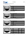
MiniRack Ethernet port numbering (when Switch is in slot 2, Line Cards in slot 3-5):
Port number:
1
2
3
4
5
8
6
7
Figure 3.5 MiniFlex MiniRack Ethernet Port numbering
17
User Manual
MiniFlex
Ethernet Port Description
P1
P2
Switch Front: RJ-45 10/100Mbps Ethernet
Switch Front: RJ-45 10/100Mbps Ethernet
P3
P4
Switch Front: RJ-45 10/100Mbps Ethernet
Switch Front: RJ-45 10/100Mbps Ethernet
P5
P8
Line Card 1: RJ-45 10/100Mbps Ethernet
Line Card 1: POE-2, if PoE Line Card used
P6
Line Card 2: RJ-45 10/100Mbps Ethernet
P7
Line Card 3: RJ-45 10/100Mbps Ethernet
Table 3.4 SubRack MiniFlex Ethernet Port Numbering.
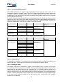
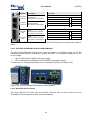
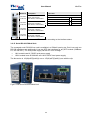
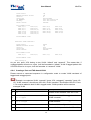
The backplane connections can be switched with a hidden Dip-Switch behind the dinrail clip.
Please see in the following figure the standard backplane connections.
Dip-Switch
Ethernet of Linecards
Figure 3.6 MiniRack backplane schematics
All backplane Ethernet interfaces of the available linecards (please see Eth5, Eth6, Eth7 on the
schematics) are connected to slot 2. There is an Ethernet Switch Linecard available for slot 2.
But the minirack can be used without the Ethernet Switch Linecard and the Ethernet interfaces
can be connected as follows by the Dip-Switch:
Switch
S1-S4 ON
Description
Ethernet Slot5 (Eth7, P7) is connected to Ethernet Bus (Eth8 Bus, P8)
S5-S8 ON
Ethernet Slot4 (Eth6, P6) is connected to Ethernet Slot5 (Eth7, P7)
S9-S12 ON
Ethernet Slot3 (Eth5, P5) is connected to Ethernet Slot4 (Eth6, P6)
Table 3.5 Switch positions of MiniRack MiniFlex.
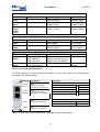
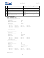
For the MiniFlex MiniRack unit there is a wallmount kit (MF-MR-RAIL-WALLMOUNT,V1) available.
18
User Manual
MiniFlex
Figure 3.7 MiniRack Wallmount Kit
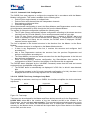
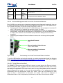
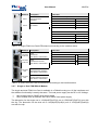
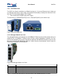
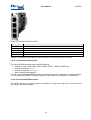
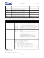
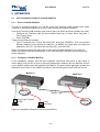
3.2.4
SHDSL Line Card
The SHDSL line card has two DSL lines with the possiblity for transmission speed up to
15.2Mbit/s per line. It means that one line card can transmit up 30.4Mbit/s with the pair bonding.
There is also a local craft terminal on every line card to manage and configure if there is any
ethernet failure of the main switch in the MiniFlex.
The two additional Ethernet interfaces on the front of the SHDSL line card can be used to
manage the line card or to have an additional Ethernet interface to transmit data in every
configured direction of the MiniFlex.
Figure 3.8 SHDSL Line Card
Element
LCT
Description
USB Connector Local Craft Terminal
RJ-45 10/100Mbps Ethernet Port 1 + two LED
RJ-45 10/100Mbps Ethernet Port 2 + two LED
LED-1
LED-2
xDSL 1/2
LED Red/Green/Amber xDSL 1
LED Red/Green/Amber xDSL 2
xDSL Connector 1/2 (4-Pin Phoenix Mini Combicom MC 1,5/4-GF-3,5)
Table 3.6 Connectors and LEDs on the front panel of SHDSL Line Card.
19
User Manual
MiniFlex
3.2.4.1 Line Card SHDSL Interface
The SHDSL interfaces can operate fully independent of each other as well as they can be
combined to operate in multipair mode. Therefore all independent SHDSL interfaces and groups
of SHDSL interfaces (multipair mode) can be configured separately from each other. The
multipair mode, the reservation mode and the automatic configuration detection mode naturally
limit the independent working.
All SHDSL interfaces support plesiochronous data transmission. It means that reference clock
frequencies, which are used to clock data transmission, are transmitted together with the data in
different directions of one SHDSL link. The clock frequencies of different SHDSL channels are
completely independent if they do not operate in the multipair mode.
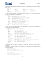
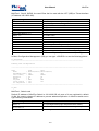
Mode
Coding Type
Baserate
Standard
Transmission
Data Rate
Master/Slave
Fix Configuration
PAM16
PAM32
3..60
12..89
Baserate* 64 kbit/s
Master
Autodetection
PAM16
PAM32
Auto (PAM16/32)
Auto (3..60)
Auto (12..89)
Auto (3..89)
Annex A, Annex B,
Annex AB
(autodetection)
Annex AB
(autodetection)
Slave
Autodetection
Annex AB
(autodetection)
Table 3.7 Line settings per SHDSL interface, single pair, normal mode.
Mode
Coding Type
Baserate
Standard
Master/Slave
Fix Configuration
PAM4
PAM8
PAM16
PAM32
PAM64
PAM128
PAM16
PAM32
PAM4/8/64/128
Auto (PAM4/8/16/
32/64/128)
2..39
3..79
1..119
1..159
2..199
4..238
Auto (1..119)
Auto (1..159)
Not possible
Auto (1..238)
Annex A, Annex B,
Annex AB
(autodetection)
Master
Autodetection
Slave
Autodetection
Transmission
Data Rate
Baserate* 64 kbit/s
Annex AB
(autodetection)
Annex AB
(autodetection)
Table 3.8 Line settings per SHDSL interface, single pair, extended mode.
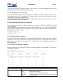
3.2.4.1.1 Master/Slave
To establish a connection, it is necessary that one transceiver side is configured as Master and
the other as Slave. In this case, the connection is controlled by the Master device.
3.2.4.1.2 Multipair Mode
If 2 SHDSL channels are configured to operate in the multipair mode, they work at the same
clock frequency and line rate like one SHDSL channel with doubled transmission capacity. This
transmission is also plesiochronous. In multipair mode, one SHDSL channel serves as a
“master” channel, while the other SHDSL channel serves as “slave” channel. If the link in one
channel fails, the links in the other channel break too and the procedure of connection/activation
restarts. The main application for the multipair mode is the increasing of the transmission range.
In this case, some channels operate at low transmission rates. In extended mode, multipair
operation is not possible!
20
User Manual
MiniFlex
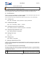
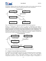
3.2.4.1.3 Automatic Link Configuration
The SHDSL line card supports to configure the complete link in accordance with the MasterModem configuration. This mode is available for the following links:
•
Point-to-Point single-channel or multipair links
•
Point-to-Point multi-channel links with independent channels
•
Star-topology multichannel links
•
Links with regenerators
When the automatic configuration is used, the Slave-Modems and Regenerators receive nearly
all configuration parameters for DSL through the link from the Master-Modem.
The system of automatic configuration operates the following way:
•
The CP side (Slave) automatically adjusts configuration according to the stream structure
received from the CO side (Master), not to cause permanent losses of user data.
•
If the CP side (Slave) cannot adjust correspondingly, it displays a RCONF alarm and
sends a message to the remote terminal device (Master). If configurations of terminal
devices (Master and Slave) do not coincide, the RCONF alarm is displayed. RCONF
means a remote urgent alarm.
The link is adjusted in the channel structure in the direction from the Master- to the SlaveModem:
•
The stream structure is configured on the Master-Modem device.
•
If there is any Regenerator in the link, it receives this structure and configures itself
according to it.
•
Also a next Regenerator receives the structure from the previous Regenerator and
performs configuration according to it.
•
The Slave-Modem receives the stream structure from the last Regenerator in the link and
also performs configuration
•
When the Slave-Modem receives configuration, the Slave-Modem also receives the
configurations of WAN. Therefore, the integrity of the Ethernet link is supported.
The RCONF alarm (displayed by the <ALARM> command) means that the local and remote
equipment have incompatible configurations.
•
The RCONF alarm is automatically not displayed if a DSL link, in which it was detected,
fails.
•
If the device operates in the CA mode (automatic configuration of a link), the alarm is not
displayed when the device finally adjusts to the CO side (Master).
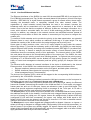
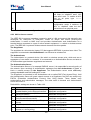
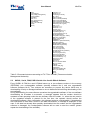
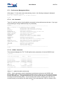
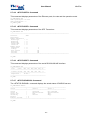
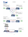
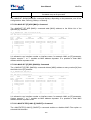
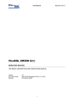
3.2.4.1.4 SHDSL Test Loop, Analogue Loop Back
The possibility to activate a test loop on SHDSL line interface simplifies the device start-andadjustment.
Master
Regenerator
Slave
Ethernet
LOOP2 1:1 ON
LOOP2 1:R ON
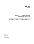
Figure 3.9. Test loops
Test loops can be activated for the Master and Slave devices as well as for the Regenerator.
LOOP2 M:N, where M is the number of the line interface and N is the number of the
Regenerator, can be activated only remotely. This command allows activating remotely a loop
back to the device, from which the command was sent. It means that if LOOP2 is activated
remotely by the Master device, the data will be looped back by the Slave device to the Master
device side, and vice versa.
21
User Manual
MiniFlex
WARNING
WHEN ACTIVATING LOOP2 UNDER CONDITIONS THAT SHDSL IS USED
TO TRANSMIT ETHERNET DATA, IT IS NECESSARY THAT THE DEVICE IS
DISCONNECTED FROM THE ETHERNET NETWORK!
Also an analogue loop back is possible. During the analogue loop back test, the SHDSL
transceiver receives the transmitted signal from its own transmitter. The analogue loop back
function (the STARTAL command is used to activate the analogue loop back) is used to test the
equipment itself.
The analogue loop back causes a non-urgent alarm of the local unit and an urgent alarm of the
remote unit.
WARNING
TO PERFORM THE ANALOG LOOPBACK, THE CABLE SHOULD BE
DISCONNECTED FROM THE UNIT!
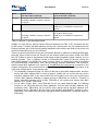
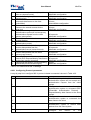
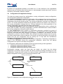
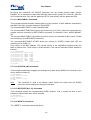
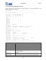
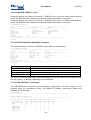
3.2.4.1.5 SHDSL Performance Monitoring (Noise Margin, G.826)
The transmission performance of a link can be monitored in two different ways. The signal
quality is typically used during installation and maintenance procedures, whereas the G.826
error performance parameters are used for long term evaluation of operating links and during
acceptance testing.
The Noise Margin (NM) provides qualitative performance information of a specific link. The NM
command is used to activate this test. This parameter is calculated according to ITU-T G.991.2
and is an efficient tool for determining the qualitative performance of an SHDSL link.
During acceptance testing, it is recommended to set the line rate or choose cable pairs (at a
fixed line rate) so that the NM value is no less that 6 dB.
An NM of 0dB in the presence of a Gaussian noise would yield an expected Bit-ErrorRatio of 10-7.
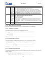
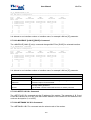
The error performance monitoring of a SHDSL link is also performed according to ITU-T Rec.
G.704. The evaluation of the G.826 error performance parameters is based on CRC (Cyclic
Redundancy Check) error detection. CRC generation and detection are performed separately
for the SHDSL interfaces.
CRC6
CRC6
SLAVE
MASTER
Receiver
Receiver
SHDSL
CRC6 FEBE
G.826
Counters
CRC6 FEBE
Generator
G.826
Counters
Generator
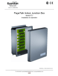
Figure 3.10 G.826 SHDSL performance evaluation
On the SHDSL side, six CRC6 check bits are generated per SHDSL frame. CRC6 errors are
used by the software to count the block errors of the SHDSL channel and to evaluate its error
performance according to ITU-T Rec. G.826.
The estimation of a bit error rate is not within the scope of G.826 calculations.
22
User Manual
MiniFlex
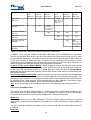
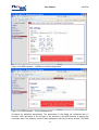
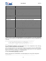
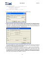
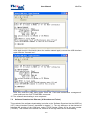
3.2.4.2 Line Card Ethernet Interface
The Ethernet interfaces of the SHDSL line card fulfil the standard IEEE 802.3 and support the
Port (PBVLAN command) and Tag (VLAN command) based VLAN protocol (Virtual Local Area
Network – IEEE 802.1Q). A virtual network represents a group of network nodes, whose traffic,
including the broadcast traffic, is completely isolated from other network nodes. The
organization of virtual networks usually decreases the load in the network, because the
broadcast traffic will be transmitted not to the entire network but to members of the VLAN
sender. Due to the fact that the members of different VLANs can exchange information via a
router, which allows a controlled traffic, the use of VLAN technology provides a high level of
security. In addition, any changes in the network structure are simplified because instead of
configuring the work station to which the modem is connected you only have to configure the
modem port.
To construct VLAN networks and to provide the priority in the data transmission, an extended
Ethernet frame is used, which contains an additional VLAN tag of 2 bytes length. The tag
includes the number of the VLAN to which the packet belongs and its priority level.
Some types of traffic (real-time video, voice or IP traffic) should be sent inside the network
without any delays. To provide the necessary quality of this traffic, the SHDSL line card devices
support Ethernet traffic priority according to the standard protocol IEEE 802.1P (so-called QoS,
Quality of Service). It means to analyze the header content of each Ethernet frame to get
information about the necessary priority of this application. The internal switch of the SHDSL
line card places this data to the corresponding queue of the output port. The SHDSL line card
equipment supports two priority queues when sending packets – a high and low priority queue.
According to it, all Ethernet traffic can be divided into high priority groups (for example VoIP
traffic or control and management channels) and low priority groups (for example LAN1 and
LAN2).
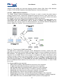
The Ethernet traffic between all network interfaces of the device is distributed by the internal
Ethernet switch. In the SHDSL line card devices three types of network interfaces exist:
•
Ethernet interfaces (external connector on the front panel, and back plane connector)
•
SHDSL interfaces (when the device is properly configured)
•
Virtual management port (Telnet session)
The choice of the interface (DSL), which will be mapped to the corresponding WAN interface is
performed by the <PAYLOAD> command.
A group of LANx Ports (Ethernet interface) means the LAN port connector on the front panel or
backplane that can serve as a Trunk port, Access port or Mixed port.
The Trunk port is a port where all present packets have the VLAN format, namely, the Ethernet
frame with a header, determining the number of the VLAN and QoS. In Trunk mode, only tagged
frames pass into and out of LANx port, frames are allowed to pass on per-VLAN basis. This
means that special equipment supporting VLAN is connected to the Trunk port. A PC with a
standard network interface card cannot be connected to the Trunk port.
The Access port is a port where all present packets have a standard Ethernet format (without
the additional two bytes for the header). It means that only untagged frames pass into (ingress)
and out of (egress) any LANx port. On ingress, frames are assigned with a default VLAN tag
(configured by VID and QoS commands). On egress, only frames with VLAN equal to the
default VLAN of the port are allowed, and this tag is removed. A PC with a standard network
interface card can be connected to the Access port.
The Mixed port is a port where tagged and untagged traffic is allowed. However, on ingress, a
default VLAN tag is assigned to untagged traffic (configured by QOS and VLAN commands), so
that all frames in the system are actually tagged. On egress frames with VLAN equal to the
default VLAN (configured with VLAN command), exit the port untagged, while to all other VLANs
apply pass/block rules set by the ALLOW command.
23
User Manual
Mode
ACCESS
Default VLAN
(set with VLAN command)
Untagged traffic outside of the modem.
VLAN1-VLAN8, OTHER
(set with ALLOW command)
Not taken into account
TRUNK
VLAN tag is added on ingress, removed
on egress.
Not taken into account
Tagged traffic outside of the modem.
MIXED
Untagged traffic outside of the modem.
VLAN tag is added on ingress, removed
on egress.
MiniFlex
VLAN tag is not modified on egress and
ingress.
Tagged traffic outside of the modem for VLANs
not equal to default VLAN.
VLAN tag is not modified on egress and
ingress.
Table 3.9 Access, Trunk and Mixed Mode
SHDSL line card devices always transmit Ethernet packets over DSL or E1 interfaces with the
VLAN format. It means that data packets coming from Access ports are first transformed into
Ethernet packets with VLAN format (adding standard VLAN number and QoS priority level) and
after this transmitted over any line interface.
There is a special case when having the same MAC address on different VLANs and PBVLANs.
Normally, there should not be two devices on the network sharing the same VLAN. But IEEE
802.1Q VLANs as well as port-based VLANs allow creating separate logical networks on one
physical network. Thus, in different VLANs or PBVLANs there could be devices sharing the
same MAC address. On SHDSL line cards, however, there is a hardware limitation preventing
all VLAN+PBVLAN combinations from having different address databases, and therefore,
allowing same MAC address to be used on all VLAN&PBVLAN combinations is possible in the
modem configuration. But, knowing which configurations are valid will allow using modems in all
really vital configurations. There are two rules.
1. For separately managed VLANs 1-8. Each VLAN has its own MAC address table, and thus
device with MAC address ABC in each of these 8 VLANs will not conflict with any device
with MAC address ABC in any other VLAN. But the limitation here is the use of port-based
VLANs. MAC address database is shared among all PBVLANs for VLAN1-8. Therefore a
device with MAC address XYZ, VLAN1, PBVLAN A, will conflict with device with MAC
address XYZ, VLAN1, PBVLAN B.
2. For all other VLANs. Here, every PBVLAN has its own MAC address table, but different
VLANs on one PBVLAN share the same database. A device with the MAC address XYZ,
VLAN(any other), PBVLAN A, will not conflict with a device having the MAC address XYZ,
VLAN(any other), PBVLAN B. But the device with the MAC address ABC, VLAN(any other),
PBVLAN A, will conflict with the device having the MAC address ABC, VLAN(any other+1),
PBVLAN A.
24
User Manual
Same MAC address
VLAN1, VID=1
PBVLAN A
VLAN1,
VID=1
PBVLAN A
N/A
VLAN other, VID=100
PBVLAN A
VLAN other, VLAN other,
VID=100
VID=200
PBVLAN A PBVLAN A
OK
OK
MiniFlex
VLAN1,
VID=1
PBVLAN B
NOK
VLAN other, VLAN other,
VID=100
VID=200
PBVLAN B PBVLAN B
OK
OK
OK
OK
OK
OK
OK
OK
N/A
OK
OK
Same MAC on
same VLAN for
VLAN=1..8
N/A
NOK
Same MAC on
same PBVLAN
for VLAN≠1..8
VLAN other, VID=200
PBVLAN A
N/A
VLAN1,VID=1
PBVLAN B
VLAN other, VID=100
PBVLAN B
N/A
NOK
Same MAC on
same PBVLAN
for VLAN≠1..8
VLAN other, VID=200
PBVLAN B
N/A
Table 3.10 Same MAC address on different VLANs and PBVLANs
In addition, every unit has a table of static MAC addresses (up to 8 addresses) for connected
devices, so that each device can have a VLAN number and a QoS priority level (this is a table
of special MAC addresses). If a packet is received from the Access port and the MAC address
of the packet sender is inside this table, a header with the necessary VLAN number and the
QoS priority will be assigned to this packet before transmitting it to the Trunk port. Otherwise, a
default VLAN number and QoS priority will be assigned to the packet.
A group of DSL ports (WAN1–WAN2) (SHDSL interface) means that Ethernet data can be
mapped onto specified timeslots (64kbit/s) on the SHDSL interface by using the internal switch.
In this case, this port always serves as a Trunk port. Any data received from Access/Mixed
ports are first transformed into Ethernet packets with VLAN format and then transmitted over
the SHDSL interface.
A virtual management port (INT) (Virtual management port) is an internal device management
program. The IP-address of this device is the logical address of the management program. For
example, to open a session for managing a remote device, the IP-address of this device should
be specified in the Telnet program. At the physical layer, the MAC address of the device is also
the management program address, which is inside the Ethernet frame.
Note: As a rule the data of the management port have the highest priority (example, QoS = 7).
3.2.4.3 Line Card MAC Filter
The system supports MAC filtering feature. If enabled the device will filter MAC addresses and
acts according to the defined MAC filtering rule. If disabled, the system will store and forward
correct Ethernet packets according to the configuration of Ethernet subsystem.
White List
White List contains a list of MAC addresses. The fact of MAC address presence in the list
means that the data exchange between the modem device and the node with selected MAC is
allowed.
The data exchange between the modem device and the node with non listed MAC address is
prohibited.
Interfaces
25
User Manual
MiniFlex
The White List is applicable per LAN Interface. Therefore the number of lists is equal to the
number of physical Ethernet ports of the device.
Note: White List can't be enabled on WAN interfaces.
Number of Entries
Every White List stores up to 10 MAC addresses. A same MAC address can be stored in
several White Lists.
3.2.4.3.1 Line Card MAC Filter Rules
MAC Address Filtering
If ingress packet has a MAC address that is not listed in the White List the LAN interface
belongs to, this packet will be dropped. No information will be recorded and no message will be
generated by the device. It is default mode and it will be enabled automatically as soon as the
MAC filtering feature will be enabled.
MAC Address Filtering and Intruder Alarm
It is possible to enable Intruder Alarm indication on the device. If enabled, the SNMP Trap will
be generated by the device if the unlisted MAC will arrive to the port. The Trap from the same
non-listed MAC address will be generated approximately once in 3 minutes. Trap contains the
information about the Intruder MAC address.
Port Blocking and Intruder Alarm
It is possible to enable Port Blocking Mode in case if unlisted MAC has been arrived. Upon
receiving the wrong MAC the Port will go to Down State equal to ETHSD OFF X command
where X is an interface number. The Intruder Alarm Trap and Link Down Traps will be
generated in this case.
NOTE: Port will keep the blocked Down State even after reset of the device. To restore port
operation the command ETHSD 10H/10F/100H/100F/AUTO X or WEB GUI shall be used.
3.2.4.4 Line Card Rapid Spanning Tree Protocol
The line card supports Rapid Spanning Tree Protocol (RSTP) according to IEEE 801.1d 2004
recommendation. All available Ethernet ports as well as all available WAN interfaces could
participate in RSTP construction. A WAN interface could be configured to carry Ethernet data
over DSL line. If several DSL links are combined into MULTIWAN, this MWAN will participate in
RSTP construction too.
The RSTP itself is a protocol used for dynamic link switching in networks with ring topology. The
ring topology improves reliability of data networks; nevertheless Ethernet networks must have
only one active path between any of two nodes to prevent packet loop. Ethernet switches with
enabled RSTP detect paths availability in a ring and quickly select active path, discarding other
paths. All RSTP-enabled devices exchange information about topology change in so-called
BPDU packets.
Root Bridge
One switch in a RSTP-enabled network must acts as Root Bridge. Root Bridge selection will be
done automatically according to Bridge ID – a unique ID that each member of RSTP network
has. Bridge ID is a combination of Switch MAC address and Bridge Priority. Switch with smallest
Bridge Priority will act as Root Bridge. If two or more switches have same priority, Switch with
less MAC address will become Root Bridge.
Port Roles
After Root Bridge has been selected, other switches define their ports role. The port that has the
shortest path to Root Bridge will become Root Port. The opposite port on the other switch will
26
User Manual
MiniFlex
become Designated Port. The Root Bridge has Designated Ports only, while other switches
have one Root port and could have Designated Port connected to other switches
A Root and Designated ports are active, they learn and forward packets. Other ports have
blocking state. They could act as Alternate port or as Backup port. Please take a look to a
picture below:
Figure 3.11 Port role definition in RSTP.
When a failure appears on a network, an alternative path will be selected and port roles will be
changed. Please take a look to a picture below:
Figure 3.12 Change of Port role upon network failure.
27
User Manual
MiniFlex
ONLY PORTS WITH ROOT AND DESIGNATED ROLES WILL FORWARD
DATA PACKETS. PORTS WITH ALTERNATIVE ROLE WILL BE IN
BLOCKED STATE
3.2.4.5 Line Card Alarm and LED Description
When managing the SHDSL line card via the local craft terminal (USB) or via Telnet, all LEDs,
except the Ethernet LEDs will blink with a frequency of 1 Hz.
The LEDs display the normal operation conditions and the alarm conditions of each line card
and of each interface according to the following tables. To display an urgent alarm has always
the highest priority and will overwrite a non-urgent alarm.
Element Description
Led Color
Status Ethernet Interface
Two LED
on RJ-45
Status
2nd Ethernet Interface
Led1=Green, Led2=Amber
Data receive and/or transmit
LED 1
LED 2
Connection is active
Connection is not active
100 Mbit/s receive/transmit rate
10 Mbit/s receive/transmit rate
Green
Off
Green Blinking
Led2
Status
1st Ethernet Interface
Led1=Green, Led2=Amber
Led1
Two LED
on RJ-45
Amber
Off
Status SHDSL Interface
Status
1st SHDSL Interface
Power failure or power is off
Status
2nd SHDSL Interface
Off
Hardware or software failure
Red Blinking
Normal operation
Green
Non urgent alarm
Amber
Urgent alarm
Red
Table 3.11 SHDSL line card LED behaviour according to the interface status.
Group
Name
Alarm
status
LED 1/2 Description
Status
SHDSL
LOS
Red
Loss of signal in an SHDSL link
LOSW
Red
Loss of frame alignment in an SHDSL link
Red
Loss of signal at the remote SHDSL side
BER-H
Red
Block-error-rate in an SHDSL line according to G.826 ≥ 30%
SEGD
Red
Loss of signal or an alarm on a regeneration segment
(segment degradation)
LOSD
SEGA
DSL
ALB
Urgent
Urgent &
Amber
Non-urgent
SHDSL analogue loop back is activated
Non-urgent Amber
Data errors or loss of frame alignment on a regeneration
segment (segment alarm)
NM
Amber
Noise Margin < setup NMTHR value
LA
Amber
Line Attenuation > setup LATHR value
LOOP2
Amber
Loop is activated from the remote device to the local device
28
User Manual
HW-F
DSL-F
Maintenance
RCONF
MiniFlex
Red
Configuration of the remote device is not compatible with the
configuration of the local device
Red
Blinking
Hardware failure
Red
Blinking
DSL signal processor initialization failure
Table 3.12 Alarm correspondance to LED behaviour
3.2.4.6 Line Card Management with Local Craft Terminal and Ethernet
Every SHDSL line card has some integrated management and diagnostic functionality, that can
be used to configure the devices and to receive additional information like G.826 parameters or
any G.SHDSL link quality.The access to this functionality is done by:
•
Connecting the local craft terminal (LCT, USB interface) to any management terminal (PC
with VT100 terminal, for example the application Hyper-Terminal).
•
Connecting the local Ethernet interface to any management terminal (PC with Ethernet
network card). In this case you access with a Telnet session or you use the WEB interface
to display some statistics. Also the SNMP (Simple Network Management Protocol) is
integrated.
•
Connecting the backplane Ethernet interface to access the unit through the integrated
Switch.
Local Craft Terminal
USB
Ethernet Interface Switch Access
Telnet, WEB, SNMP
Ethernet Interface Front Access
Telnet, WEB, SNMP
Figure 3.13 SHDSL Line Card showing Local Craft Terminal and Ethernet Interface
To use the USB interface as local craft terminal, you need to download and install the following
driver http://www.flexdsl.ch/extranetfiles/Software/Orion3_USB_Driver.zip. This is an USB to
serial driver and allow to have a COM port over USB.
3.2.4.6.1 Telnet (Ethernet Interface)
The TELNET (TELecommunication NETwork) access is made through the Ethernet network.
With any computer and a program with the Telnet protocol SHDSL line cards can be fully
managed. After opening the Telnet session, there is a user authentication: “admin” users, who
can change configurations and “user” users who can only view parameters and statistics.
Initially passwords are empty. In this case the authentication is not performed and users
automatically have the administrator rights. Only “admin” users can set passwords for both
types of users. If authentication is successful, the modem main menu is displayed. If
authentication fails, it can be repeated up to three times, and after it the connection breaks.
29
User Manual
MiniFlex
Example: The management through a Telnet session can be activated by a standard command
on any Windows computer: telnet <IP-address>
If no symbols are received by the modem over the telnet connection within 5 minutes, this
session breaks. And with correct configuration, every SHDSL line card with an IP address can
be reached; it does not matter if near end, far end or repeater.
3.2.4.6.2 WEB (Ethernet Interface)
The WEB interface is used to display statistics and do configuration when the SHDSL line cards
are connected to the management computer via any Ethernet interface. Any WEB browser can
be used to access the WEB interface. To display the statistics you should enter the command:
http://X.X.X.X on the WEB browser. (X.X.X.X is the IP-address of the modem). After the
connection is established, the active window of the WEB browser displays the following alarms
and statistics (there are several pages available):
Figure 3.14 WEB interface – “SHDSL Line Card Alarms”
If you chose the configuration menu you have some tabs for the configuration. Please check
under the command description if you need some explanation about any setting. If you have
changed the configuration you have to press the “Save” button. The configuration is then active
and if you like to have the configuration stored you have to change to the tab “Device
Management” and press the “Confirm” button.
30
User Manual
MiniFlex
Figure 3.15 WEB interface – “SHDSL Line Card Configuration”
Figure 3.16 WEB interface – “Device Management”
All tables are displayed dynamically. The parameters in the tables are refreshed every 5
seconds. Click the button in the left part of the window of the WEB browser to display the
necessary table. The software version is also displayed in the left part of the window. The WEB
31
User Manual
MiniFlex
interface of the SHDSL line card has following windows: Alarms, DSL Status, DSL Statistics
(G.826), TCP/IP & ICMP Statistics, Net (WAN) Statistics, Command Reference.
3.2.4.6.3 SNMP (Ethernet Interface)
The SNMP (Simple Network Management Protocol) is used to monitor the status and to
manage network devices. Unlike other management protocols such as Telnet, SSH and HTTP,
the SNMP protocol not only allows an operator to manage the unit, but also informs him about
the changes in the device status when management session was inactive.
The SNMP protocol has a client-server background. The modems act as SNMP-Agents, they
communicate with the SNMP-Server that is actually a software and available free or
commercially from various vendors for different platforms. The FlexView Network Management
System (NMS) from FlexDSL Telecommunications AG is available too.
Figure 3.1. The structure of SNMP-based NMS.
The NMS Server authenticates local and remote Management Consoles, interact with other
NMS Servers, sends and receives SNMP messages and stores various databases including the
MIB database. The Management Information Base (MIB) is a plain text file that has to be
imported into the SNMP Server for the purpose of translation the Object Identification (OID)
numbers and their content to the human readable format. For example, it is requested to check
the status of LAN port. The network administrator can check the SNMP variable with the OID
1.3.6.1.2.2.1.2.2.1.8 path, or, if using MIB file, the same variable can be reachable at the
RFC1213-MIB|ifOperStatus address. Its content can be "2" in the first example, or "down" if MIB
file is used.
The following MIB files are supported:
•
•
•
•
•
•
•
•
•
MIB II RFC1213-MIB, a standard MIB for all devices is fully supported
IF-MIB, RFC-2863, MIB descriptions of interfaces is fully supported
NATEKS-MIB, MIB for the Nateks/FlexDSL equipment is fully supported
DS1-MIB, RFC-2495, MIB describing E1 streams is partially supported
RMON-MIB, RFC-2819 remote monitoring for statistics is fully supported
RS-232-MIB, RFC-1659 for serial interfaces is partially supported
BRIDGE-MIB, RFC-4188, a standard MIB for Ethernet Bridges is fully supported
Q-BRIDGE-MIB, RFC-4363, an extended MIB for Ethernet Bridges is partially supported
RSTP-MIB, RFC-4318, an extended MIB for RSTP protocol is fully supported
32
User Manual
MiniFlex
Local and Remote Management Console are intended for the graphical representation of
network map, device icons and device views. It accepts the user actions such as mouse clicks,
zooming, key pressings, etc. The Management Console interacts with the SNMP Server via the
Remote Procedure Call (RPC) data in TCP/IP envelope. The Management Console can coexist
with the SNMP-Server on the same PC or work on a separate computer.
Network Elements are copper and fiber modems, converters and other network devices.
Network Elements support the following versions of SNMP protocol:
•
•
•
V1, is initial version of SNMP protocol
V2c, is the updated version of SNMP protocol featured bulk requests and long counters
V3, is the latest version featured authentication and message encryption. Two users are
actually supported.
Depending on the SNMP protocol version, the following SNMP messages are supported:
•
•
•
for the SNMP V1: GET, GET NEXT, SET, TRAP
for the SNMP V2c: GET, GET NEXT, GET BULK, SET, TRAP
for the SNMP V3: READ, WRITE, TRAP
GET and READ messages initialized by the SNMP Server and intended for getting information
from the Network Element.
SET or WRITE message initialized by the SNMP Server and intended for changing the SNMP
variable of the Network Element.
TRAP messages initiated by the Network Element. These messages carry information about
status change of the Network Element. For example, if port goes Down or Up, if the device have
been restarted, or if the alarm appeared, the TRAP message will be send to the direction of the
SNMP Server. Two destinations are supported for TRAP messages.
The following TRAP messages are supported:
•
•
•
•
•
•
•
•
cold Start (RFC-1215)
authentication Failure (RFC-1215)
linkUp (RFC-1213-MIB, IF-MIB)
linkDown (RFC-1213-MIB, IF-MIB)
dsx1LineStatusChange (DS1-MIB)
device specific traps (nateks.mib)
newRoot and topologyChange (RFC-4188, BRIDGE-MIB)
RMON Event (RMON-MIB)
Figure 3.2. Message exchange in SNMP-based networks.
33
User Manual
MiniFlex
NOTE: The NMS Server is not involved into the message exchange for management
protocols such as Telnet, SSH and HTTP. These sessions are initiated between Management
Console and Network Element directly.
3.2.4.6.4 SSH
The SSH (Secure SHell) protocol is used to access MiniFlex devices over IP networks. Unlike
Telnet, the SSH packets are encrypted with a key and can't be read if intercepted by an
intruder. Therefore User data such as login and password credentials can be safely transmitted
over public networks.
The MiniFlex modem acts as SSH server. It listens default TCP Port 22 for incoming
connections from remote clients and initialises Login/Password sequence if connection appears.
Default Port 22 can be changed for the security reasons.
User will have an access to the CLI after successful login.
The SSH client is a software for PC. We suggest to use PuTTY for the Microsoft (c) Windows
and build-in ssh client for Linux/Unix/MACOS X systems.
NOTE: On Linux/UNIX/MACOS X systems run ssh command with -l parameter to specify the
device login name if it is differs from the name of a user who initialise the SSH session.
3.2.4.6.5 RADIUS
The RADIUS (Remote Authentication in Dial-In User Service) is used to authenticate and
authorise remote devices from the single place. Unlike the local authentication and
authorisation, where USERNAME/PASSWORD/ACCESS_RIGHTS have to be created for every
single unit in the network, the RADIUS authentication and authorisation means that user
credentials must be created and stored only once on the RADIUS server. The remote RADIUS
clients will connect to the RADIUS server and request user authentication and authorisation.
NOTE: RADIUS subsystem depends on Advanced Security settings. SECURE ON
command has to be enabled before activating the RADIUS service
The MiniFlex modem acts as RADIUS client. It will request user authentication and authorisation
from RADIUS server if operator will access command line or WEB interface of the device.
NOTE: The current realisation of RADIUS protocol is designed for authentication and
authorisation of the device operator. It is not intended for granting or disallowing an access
from LAN ports to the network.
MiniFlex RADIUS client supports one or two RADIUS servers. The following options are
configurable:
Parameter
Server IP
Server port
Value
IP Address
0-65535
Shared key
String (64
symbols)
Retries
0-10
Timeout, seconds
1-5
Description
IP address of primary and secondary RADIUS Server.
UDP Port, the RADIUS server is listen on for incoming
connections. Default port is 1812.
A passphrase. It must be the same for RADIUS server and all
clients. If two RADIUS servers are used, the passphrase can
be unique for each server.
Number of retries, the client will use to authenticate the user
on both RADIUS servers. 0 means no attempts. Default value
is 2.
Time interval between authentication attempts. Default value
is 2 seconds.
34
User Manual
MiniFlex
The authentication and authorisation process has the following scenario: as soon as operator
opens console session through Telnet, SSH or Serial interface, or if he opens WEB session and
connects to the HTTP server of the device, the LOGIN prompt appears. Operator enters the
USERNAME/PASSWORD pair and the RADIUS client (modem) sends authentication request to
the first RADIUS server. If the USERNAME/PASSWORD pair match the server database, the
operator will be authorized and access to CLI or WEB interface will be granted. If either
USERNAME/PASSWORD pair, or shared key doesn't match the server database record, the
access will be disallowed. Operator has 3 attempts per session to authenticate himself.
If first RADIUS server didn't reply during a defined timeout, the build-in modem RADIUS client
tries to authenticate the user at the second RADIUS server. If the second server didn't reply, the
client tries the first server again. This sequence keeps running until the number of retries
counter expires. The number of retries is user defined.
If the whole authentication sequence fails, the build-in modem RADIUS client tries to
authenticate and authorise the operator using the local user record.
NOTE: It is not possible to authenticate user with local user record, if at least one RADIUS
server is running and accessible from the build-in client.
3.2.4.6.5.1 RADIUS Server Setup with Defined Vendor Specific Attributes
As an example we will configure freeradius server running on Linux Debian/Ubuntu platform.
Server will use Vendor Specific Attributes field during message exchange.
Freeradius server can store its configuration in SQL database or in plain text files. We will select
second way because of simplicity.
Vendor configuration. File dictionary.flexdsl
First of all we need to tell freeradius server to use Vendor Specific Attribute for the access to
FlexDSL equipment. We need to create the following text file:
File is located at /usr/share/freeradius/dictionary.flexdsl
#
#
# Radius settings for FlexDSL units
#
#
VENDOR
FlexDSL
4249
BEGIN-VENDOR
ATTRIBUTE
END-VENDOR
FlexDSL
FlexDSL-Rights
FlexDSL
0
string
As a second step we need to connect newly created Vendor Specific file to the freeradius
dictionary file:
File is located at /usr/share/freeradius/dictionary
String to add:
$INCLUDE dictionary.flexdsl
If Vendor Specific Attributes are used, the server will send the message containing two fields:
<Vendor-Specific> <4249 0 ACCESS_RIGHTS_STRING>. Here 4249 is Vendor ID of FlexDSL
Telecommunications AG. ACCESS_RIGHTS_STRING contains the user privileges.
Client configuration. File clients.conf.
We need to define RADIUS clients
Client configuration file contains the IP addresses of the modems with build-in RADIUS clients
and shared secret passphrase. File is located at /etc/freeradius/clients.conf
# FlexDSL MiniFlex Clients
# Modems from network 192.168.1.0/24 will be authenticated using secret
35
User Manual
MiniFlex
# phrase. Don't forget to add "sharing secret" to Orion3 modem using
# RADIUS SECRET command
client 192.168.1.0/24 {
secret = My1stSecretCode4Radius
require_message_authenticator = no
nastype = other
}
User configuration. File users
We need to create USERS with appropriate rights
User records are located at /etc/freeradius/users
# MiniFlex User with Administration rights
MINIFLEXADMIN Cleartext-Password := "AdminPass"
FlexDSL-Rights = ALL,
Framed-IP-Address = 192.168.169.0,
Framed-IP-Netmask = 255.255.255.0
# MiniFlex User with User rights. Basic change of configuration
MINIFLEXUSER Cleartext-Password := "UserPass"
FlexDSL-Rights = CONTROL,
FlexDSL-Rights += TEST,
FlexDSL-Rights += STATUS,
FlexDSL-Rights += CONFIG,
Framed-IP-Address = 192.168.169.0,
Framed-IP-Netmask = 255.255.255.0
# MiniFlex User with Read-only rights
MINIFLEXOPERATOR Cleartext-Password := "OperatorPass"
FlexDSL-Rights = TEST,
FlexDSL-Rights += STATUS,
Framed-IP-Address = 192.168.169.0,
Framed-IP-Netmask = 255.255.255.0
NOTE: Don`t forget to restart freeradius server after changing configuration using
sudo service freeradius restart command.
3.2.4.6.5.2 Simplified RADIUS Server Setup
Alternatively we can setup the freeradius server without Vendor Specific dictionary file and
declare Vendor-Specific field in user configuration file instead
User configuration. File users
We need to create USERS with appropriate rights
User records are located at /etc/freeradius/users
# MiniFlex User with Administration rights
MINIFLEXADMIN Cleartext-Password := "AdminPass"
Vendor-Specific = ALL,
Framed-IP-Address = 192.168.1.0,
Framed-IP-Netmask = 255.255.255.0
# MiniFlex User with User rights. Basic change of configuration
MINIFLEXUSER Cleartext-Password := "UserPass"
Vendor-Specific = CONTROL,
Vendor-Specific += TEST,
Vendor-Specific += STATUS,
Vendor-Specific += CONFIG,
Framed-IP-Address = 192.168.1.0,
Framed-IP-Netmask = 255.255.255.0
# MiniFlex User with Read-only rights
MINIFLEXOPERATOR Cleartext-Password := "OperatorPass"
Vendor-Specific = TEST,
36
User Manual
MiniFlex
Vendor-Specific += STATUS,
Framed-IP-Address = 192.168.1.0,
Framed-IP-Netmask = 255.255.255.0
Without Vendor Specific Attributes defined, the server will send the message containing two
fields:
<Vendor-Specific> <ACCESS_RIGHTS_STRING>. No vendor ID will be attached to the
message.
Client configuration file contains the same information as in the previous example.
Client configuration. File clients.conf.
We need to define RADIUS clients
Client configuration file contains the IP addresses of the modems with build-in RADIUS clients
and shared secret passphrase. File is located at /etc/freeradius/clients.conf
# FlexDSL MiniFlex Clients
# Modems from network 192.168.1.0/24 will be authenticated using secret
# phrase. Don't forget to add "sharing secret" to MiniFlex modem using
# RADIUS SECRET command
client 192.168.1.0/24 {
secret = My1stSecretCode4Radius
require_message_authenticator = no
nastype = other
}
NOTE: Don`t forget to restart freeradius server after changing configuration using
sudo service freeradius restart command.
3.2.4.6.5.3 Configuring User Access Rights
The <Vendor-Specific> or <FlexDSL-Rights> field in RADIUS configuration tells the client what
access rights the user has. It is possible to grant or discard access to various commands and
menu items of the modem device. All commands of the CLI are divided into 3 levels. Selection
of upper level means that the commands from low levels will be selected too. Some commands
are available for every user, they can’t be revoked.
Privileges
Hierarchy Levels
Top
Group
Level
ALL
Description
Related commands
ALARM
ALARM T
DISCONNECT
LINKCLEAR
TLM
SENSOR
ACO
SOFTINFO
CONTROL
[CTRL]
TEST
[T]
Commands of
this level are
available for
everyone. No
additional
authorization is
required
Operation of
remote devices
Test of the
device
CONNECT
LINK
ADMIN
[A]
Administration of
the device
LOOP1
LOOP2
STARTAL
RESTART
DIFF
DUMP
SERNUM
LICENSE
ACO change
PING
MACTABLE
MACTABLE C
BERT Submenu
SOFTUPDATE
SOFTCONFIRM
ID
RESPONSE
PASSWORD
Subgroup
37
User Manual
MiniFlex
RESET
BACKUP
RESTORE
LOAD
TLM D
TLM S
TLM C
SENSOR
[O/C]
TFTP
STATUS
[S]
:LINK
Link status
:LINKC
All commands
from LINK + reset
of the counters
Ethernet status
:LAN
ALL
CONFIG
[C]
:LANC
All commands
from LAN + reset
of Ethernet
counters and
MAC table
:VIEW
Displaying of
device
configuration
All commands
from VIEW +line,
E1 and Nx64
interface
configuration
:LINK
:LAN
All commands
from VIEW + LAN
configuration
:SNMP
All commands
38
[N]
G826
G826 C
G826 E1
G826 E1 C
ALLG826
LINKSTAT
LINKALARM
ALARMLOG
RESETG826
RESETALLG826
NMTHR
LATHR
LICENSE ADD
DEFAULT
EVERYTHING
SECURE
LOG
USERS
USER
APPLY
CONFIRM
NM
LINKNM
STATUS
STATUS T
STATUS L
STATUS EXT
POWER DIAG
ALARMLOG C
NETSTAT
NETERR
RESETNETSTAT
MACTABLE C
STATUS ETH
MACTABLE
CONFIG
NETCONFIG
COSCONFIG
RSTP CONF
DEFAULT
AUTO
MASTER
EXT
BASERATE
PAM
PAYLOAD
ANNEX
SETCLOCK
MULTIPAIR
RESERVE
G704
CRC4
AISDET
AISGEN
DSLTS
WANTS
NETDEFAULT
RSTP DEFAULT
RSTP STATE
RSTP ...
PBVLAN
MODE [IF]
VLAN
QOS
ALLOW
VID
TRAPIP
E1CLOCK
E1MODE
POWER
GSCOMPAT
PTMP
MODE N
RSRATE
RSFORMAT
RSDUPLEX
AUTOLOOP
EXTCLOCK
N64RATE
WAN
WANIDLE
APPLY
CONFIRM
ETHSD
FC
IRATE
ERATE
CRATE
COS
PING
APPLY
CONFIRM
RMONALARM
User Manual
:NET
from VIEW +
SNMP
configuration
All commands
from VIEW + IP
configuration
MiniFlex
COMMUNITY
SNMPSET
SNMPACL
SETIP
GATEWAY
NETMASK
MTU
SYSLOG
RMONEVENT
APPLY
CONFIRM
SNTP
APPLY
CONFIRM
PING
NOTE: The abridgements in braces “[ ]” can be entered instead of complete name.
If group has been entered without subgroup definitions, all subgroups will become available.
To define subgroup, type it after group name with “:” in the beginning of a subgroup.
The WEB interface will follow the rights of CLI interface.
In the RADIUS Server configuration example three different users have been defined in the
users file.
User MINIFLEXADMIN has full access to the device, because <Vendor-Specific> or <FlexDSLRights> field is set to ALL.
MINIFLEXUSER has partial access, because <Vendor-Specific> or <FlexDSL-Rights> filed is
set to CONTROL + TEST + STATUS + CONFIG.
MINIFLEXOPERATOR can only perform tests and check device status, because <VendorSpecific> or <FlexDSL-Rights> field is set to TEST + STATUS.
3.2.5
SHDSL DINrail Modem
The SHDSL Line Card is available in a DINrail housing too. All the interfaces and the software
functionality is exactly the same. The local power supply can be DC or AC Voltage:
•
•
-24V models have18-72VDC local power supply
-230V models have 85-264VAC and 120-370VDC local power supply
The dimension is 143(W)x87(D)x37(H) mm or 153(W)x87(D)x37(H) mm with the clip.
Figure 3.17 SHDSL DINrail Modem
3.2.6
Single or Dual FOM Line Card
The FOM Line Card has one or two SFP slot interface for any SFP module (100Base-FX, OC3/STM-1). There is also a local craft terminal on every line card to manage and configure if there
is any ethernet failure of the main switch in the MiniFlex.
39
User Manual
MiniFlex
Figure 3.18 Single and Dual FOM Line Cards
Element
LCT
LED-1
LED-2
SFP
Description
USB Connector Local Craft Terminal
LED Red/Green/Amber Ethernet Backside
LED Red/Green/Amber SFP slot Frontside
SFP slot for any module with speed up to 155Mbps.
Table 3.13 Connectors and LEDs on the front panel of the single FOM Line Card.
Element
LCT
Description
USB Connector Local Craft Terminal
RJ-45 10/100Mbps Ethernet Port 1 + two LED
RJ-45 10/100Mbps Ethernet Port 2 + two LED
LED-1-1 LED-1-2
SFP
LED Red/Green/Amber SFP slot Frontside
SFP slot for any module with speed up to 155Mbps.
LED-1-1 LED-1-2
SFP
LED Red/Green/Amber SFP slot Frontside
SFP slot for any module with speed up to 155Mbps.
Table 3.14 Connectors and LEDs on the front panel of the dual FOM Line Card.
3.2.6.1 Line Card SFP and Ethernet Interface
Please see the interface description of the SHDSL line card.
3.2.6.2 Line Card Alarm and LED Description
The LEDs display the normal operation conditions and the alarm conditions of each line card
and of each interface according to the following tables. To display an urgent alarm has always
the highest priority and will overwrite a non-urgent alarm.
40
User Manual
Element Description
LED 1
LED 2
MiniFlex
Led Color
Status
Ethernet Interface
Backplane
Status Ethernet Backplane Interface
Connection is not active
Off
Status
SFP Module
Data receive and/or transmit
Amber Blinking
System Error
Red
Power fail
Off
Connection is active
Green
Status SFP Interface
Connection is active
Green
Data receive and/or transmit
Amber Blinking
No SFP module inserted
Off
Power fail
Off
Table 3.15 Single FOM Line Card LED behaviour according to the interface status.
Element Description
Status Ethernet and SFP Interface
Status
2nd Ethernet Interface
Led1=Green, Led2=Amber
Data receive and/or transmit
Two LED
SFP
Status
1st SFP Ethernet Interface
Led1=Green, Led2=Amber
Two LED
SFP
Status
2nd SFP Ethernet Interface
Led1=Green, Led2=Amber
Connection is active
Connection is not active
100 Mbit/s receive/transmit rate
10 Mbit/s receive/transmit rate
Green
Off
Green Blinking
Led2
Two LED
on RJ-45
Status
1st Ethernet
Led1=Green, Led2=Amber
Led1
Two LED
on RJ-45
Led Color
Amber
Off
Table 3.16 Dual FOM Line Card LED behaviour according to the interface status.
3.2.7
Single or Dual FOM DINrail Modem
The single and dual FOM Line Card is available in a DINrail housing too. All the interfaces and
the software functionality is exactly the same. The local power supply can be DC or AC Voltage:
•
•
-24V models have18-72VDC local power supply
-230V models have 85-264VAC and 120-370VDC local power supply
The dimension for the single one is 143(W)x87(D)x37(H) mm or 153(W)x87(D)x37(H) mm with
the clip. The dimension for the dual one is 143(W)x87(D)x43(H) mm or 153(W)x87(D)x43(H)
mm with the clip.
41
User Manual
MiniFlex
Figure 3.19 Single and Dual FOM DINrail Modem
3.2.8
POE Line Card
ATTENTION
The POE (power over Ethernet) line card has two Ethernet ports suporting
the IEEE 802.3af standard with 15.4 Watts. Attention, this line card can only
be used with the Minirack (MF-MR-RAIL-2U4S,V1) and not with the normal
subrack (MF-MR2N-SW-12Eth,V1).
Figure 3.20 POE Line Card
Element
Description
RJ-45 10/100Mbps Ethernet Port 1 + two LED
RJ-45 10/100Mbps Ethernet Port 2 + two LED
LED-1
LED-2
LED Green POE status 1
LED Green POE status 2
Table 3.17 Connectors and LEDs on the front panel of POE Line Card
The POE Line Card can be configured by jumpers for the wished powering scheme.
42
User Manual
MiniFlex
Mode A
802.3af PoE Mode A combine’s power onto the
same wires as the data signal using a technique
called Phantom Powering
Mode B
802.3af PoE Mode B uses the Ethernet spare
pairs 4/5 and 7/8 to carry power. Pairs 1/2 and
3/6 are left untouched and carry data for
10/100BaseT.
Figure 3.21 Jumpers on POE Line Card
Internal/External Power
X301 & X302
Mode
Pin1-3
Default Mode 15.4
Pin2-4
Watts per Interface.
IEEE802.3af
Pin3-5
External
Power
Pin4-6
Mode. 40.0 Watts per
Interface IEEE802.3at
Condition
Power at PD
External Power must be 12.95Watts
18-72VDC. POE uses on
board DC/DC converter.
External Power must be 34.20Watts
44-54VDC. POE uses
external power.
43
User Manual
Mode A and Mode B Configuration
X404 & X405
Mode
Pin1-2
Mode A
Pin5-6
Pin3-4
Mode B
Pin7-8
Pin1-2
Mode A & Mode B
Pin3-4
Pin5-6
Pin7-8
Power Polarity MDI or MDI-X
X402 & X403
Polarity
Pin1-3
MDI-X
Pin2-4
Pin3-5
MDI
Pin4-6
Special Combined Mode A and Mode B
X406
Pin1-3
PoE-1 Mode A
Pin2-4
PoE-1 Mode B
PoE-2 not used
Pin3-5
PoE-1 normal use
Pin4-6
PoE-2 normal use
MiniFlex
Condition
X404 for PoE-2
X405 for PoE-1
X404 for PoE-2
X405 for PoE-1
X404 for PoE-2
X405 for PoE-1
Power at PD
Depending X301
& X302 & X406
Depending X301
& X302 & X406
Depending X301
& X302 & X406
Mode A
Pin1/2 -48VDC
Pin3/6 0VDC
Pin1/2 0VDC
Pin3/6 -48VDC
Mode B
Pin4/5 -48VDC
Pin7/8 0VDC
Pin4/5 0VDC
Pin7/8 -48VDC
Condition
PoE-1 uses two on board
DC/DC converter. One for
Mode A other for Mode B.
Default
Power at PD
2x 12.95Watts
Depending X301
& X302
3.2.8.1 Line Card LED Description
The LEDs display the normal operation conditions of each line card and of each interface
according to the following table.
Element Description
LED 1
LED 2
Status Ethernet Interface
Status
2nd Ethernet Interface
Led1=Green, Led2=Amber
Data receive and/or transmit
Connection is active
Connection is not active
100 Mbit/s receive/transmit rate
10 Mbit/s receive/transmit rate
Green
Off
Green Blinking
Led2
Two LED
on RJ-45
Status
1st Ethernet Interface
Led1=Green, Led2=Amber
Led1
Two LED
on RJ-45
Led Color
Amber
Off
Status POE on Ethernet Interface
Status
1st Power over Ethernet
Power is off
Off
Normal operation, Power is on
Green
Status
2nd Power over Ethernet
Table 3.18 POE Line Card LED behaviour according to the interface status.
44
User Manual
3.2.9
MiniFlex
POE DINrail Unit
The POE Line Card is available in a DINrail housing too. It has one Ethernet input (LAN) and
one Ethernet with Power output (PoE). All interfaces functionality is exactly the same as for the
line card. The local power supply is DC Voltage:
•
-24V model has18-72VDC local power supply
The dimension is 143(W)x87(D)x37(H) mm or 153(W)x87(D)x37(H) mm with the clip.
Figure 3.22 POE DINrail Unit
3.2.10 Managed Switch Line Card
The managed Switch Line Card has four 10/100Base-T Ethernet ports as front access and up to
additional four 10/100Base-T Ethernet ports as back access (backplane). Attention, the four
ports at the backplane can only be used with the Minirack (MF-MR-RAIL-2U4S,V1) and not with
the normal subrack (MF-MR2N-SW-12Eth,V1). When using a normal subrack, there is only one
Ethernet port available at the backplane.
Figure 3.23 Managed Switch Line Card
Element
LCT
Description
USB Connector Local Craft Terminal
RJ-45 10/100Mbps Ethernet Port 1 + two LED
RJ-45 10/100Mbps Ethernet Port 2 + two LED
RJ-45 10/100Mbps Ethernet Port 3 + two LED
RJ-45 10/100Mbps Ethernet Port 4 + two LED
Table 3.19 Connectors and LEDs on the front panel of the managed Switch Line Card.
45
User Manual
MiniFlex
3.2.10.1 Line Card LED Description
The LEDs display the normal operation conditions of each line card and of each interface
according to the following table.
Element Description
Status Ethernet Interface
Status
2nd Ethernet Interface
Led1=Green, Led2=Amber
Data receive and/or transmit
Two LED
on RJ-45
Status
3rd Ethernet Interface
Led1=Green, Led2=Amber
Two LED
on RJ-45
Status
4th Ethernet Interface
Led1=Green, Led2=Amber
Connection is active
Connection is not active
100 Mbit/s receive/transmit rate
10 Mbit/s receive/transmit rate
Green
Off
Green Blinking
Led2
Two LED
on RJ-45
Status
1st Ethernet Interface
Led1=Green, Led2=Amber
Led1
Two LED
on RJ-45
Led Color
Amber
Off
Table 3.20 Managed Switch Line Card LED behaviour according to the interface status.
3.2.11 Managed Switch DINrail Unit
The Managed Switch Line Card is available in a DINrail housing too. All the interfaces and the
software functionality is exactly the same. The local power supply can be DC or AC Voltage:
•
•
-24V models have18-72VDC local power supply
-230V models have 85-264VAC and 120-370VDC local power supply
The dimension is 143(W)x87(D)x43(H) mm or 153(W)x87(D)x43(H) mm with the clip.
Figure 3.24 Managed Switch DINrail Unit
3.2.12 Serial RS-232/422/485 Interface Line Card
The Serial RS-232/422/485 Line Card has one serial interface, two SFP slot interface for any
SFP module (100Base-FX, OC-3/STM-1) and an additional 10/100Base-T Ethernet port as front
access and one Ethernet ports as back access (backplane). There is also a local craft terminal
on every line card to manage and configure if there is any ethernet failure of the main switch in
the MiniFlex.
46
User Manual
MiniFlex
Figure 3.25 Serial RS-232/422/485 Interface Line Card
Element
LCT
Description
USB Connector Local Craft Terminal
RJ-45 Serial Port + two LED
RJ-45 10/100Mbps Ethernet Port + two LED
LED-1-1 LED-1-2
SFP
LED Red/Green/Amber SFP slot Frontside
SFP slot for any module with speed up to 155Mbps.
LED-1-1 LED-1-2
SFP
LED Red/Green/Amber SFP slot Frontside
SFP slot for any module with speed up to 155Mbps.
Table 3.21 Connectors and LEDs on the front panel of the Serial RS-232/422/485 Interface Line
Card.
3.2.12.1 Line Card SFP and Ethernet Interface
Please see the interface description of the SHDSL line card.
3.2.12.2 Line Card Serial RS-232/422/485 Interface
The serial interface can be configured to be RS-232 or RS-422/485 with following features:
•
Speed 75, 150, 300, 600, 1200, 2400, 4800, 9600, 14400, 19200, 28800, 38400, 56000,
57600, 115200, 230400 bps
•
number of data bits: 5…8
•
number of stop bits:1, 1.5 or 2
•
parity: odd/even/mark/space
You can use the command RSRATE [N] to set the baud rate (N is baudrate, for instance 9600).
The command RSFORMAT [format] is used to set the data format (example of format: 8N1).
3.2.12.3 Line Card Alarm and LED Description
The LEDs display the normal operation conditions and the alarm conditions of each line card
and of each interface according to the following tables. To display an urgent alarm has always
the highest priority and will overwrite a non-urgent alarm.
47
User Manual
Element Description
Two LED
SFP
Status Ethernet and SFP Interface
Status
Ethernet Interface
Led1=Green, Led2=Amber
Data receive and/or transmit
Status
1st SFP Ethernet Interface
Led1=Green, Led2=Amber
Status RS-232/422/485 Interface
Status
2nd SFP Ethernet Interface
Led1=Green, Led2=Amber
RS-232 control RTS/CTS
Connection is active
Connection is not active
100 Mbit/s receive/transmit rate
10 Mbit/s receive/transmit rate
RS-232 data receive/transmit
RS-422/485 data receive/transmit
RS-422/485
Green
Off
Green Blinking
Led1 Led2
Two LED
SFP
Status
Serial Interface
Led1=Green, Led2=Amber
Led2
Two LED
on RJ-45
Led Color
Led1
Two LED
on RJ-45
MiniFlex
Amber
Off
Green RX/TX
Green RX/TX
Amber R/CTS
Off
Table 3.22 Serial RS-232/422/485 Interface Line Card LED behaviour according to the interface
status.
3.2.13 Serial RS-232/422/485 Interface DINrail Modem
The Serial RS-232/422/485 Interface Line Card is available in a DINrail housing too. All the
interfaces and the software functionality is exactly the same. The local power supply can be DC
or AC Voltage:
•
•
-24V models have18-72VDC local power supply
-230V models have 85-264VAC and 120-370VDC local power supply
The dimension is 143(W)x87(D)x43(H) mm or 153(W)x87(D)x43(H) mm with the clip.
Figure 3.26 Serial RS-232/422/485 Interface DINrail Modem
3.2.14 Serial RS-232 Line Card
The Serial RS-232 Line Card has four RS-232 (V.24/28) ports as front access and one
10/100Base-T Ethernet ports as back access (backplane).
48
User Manual
MiniFlex
Figure 3.27 Serial RS-232 Line Card
Element
LCT
Description
USB Connector Local Craft Terminal
RJ-45 RS-232 Port 1 + two LED
RJ-45 RS-232 Port 2 + two LED
RJ-45 RS-232 Port 3 + two LED
RJ-45 RS-232 Port 4 + two LED
Table 3.23 Connectors and LEDs on the front panel of the Serial RS-232 Line Card.
3.2.14.1 Line Card Serial Interface
The serial RS-232 interfaces have following features:
•
Speed 75, 1200, 2400, 9600, 19200, 38400, 57600, 115200, 230400 bps
•
number of data bits: 5…8
•
number of stop bits:1, 1.5 or 2
•
parity: odd/even/mark/space
You can use the command RSRATE [N] to set the baud rate (N is baudrate, for instance 9600).
The command RSFORMAT [format] is used to set the data format (example of format: 8N1).
3.2.14.2 Line Card LED Description
The LEDs display the normal operation conditions of each line card and of each interface
according to the following table.
49
User Manual
Element Description
Led Color
Status RS-232/422/485 Interface
Two LED
on RJ-45
Status
2nd RS-232 Interface
Led1=Green, Led2=Amber
RS-232 control RTS/CTS
Two LED
on RJ-45
Status
3rd RS-232 Interface
Led1=Green, Led2=Amber
Two LED
on RJ-45
Status
4th RS-232 Interface
Led1=Green, Led2=Amber
RS-232 data receive/transmit
RS-422/485 data receive/transmit
RS-422/485
Led1 Led2
Status
1st RS-232 Interface
Led1=Green, Led2=Amber
Two LED
on RJ-45
MiniFlex
Green RX/TX
Green RX/TX
Amber R/CTS
Off
Table 3.24 Serial RS-232 line card LED behaviour according to the interface status.
3.2.15 Serial RS-232 DINrail Unit
The managed serial RS-232 line card is available in a DINrail housing too. But it has only two
RS-232 interfaces and additionally it has two SFP slot interfaces for any SFP module (100BaseFX, OC-3/STM-1). The local power supply can be DC or AC Voltage:
•
•
-24V models have18-72VDC local power supply
-230V models have 85-264VAC and 120-370VDC local power supply
The dimension is 143(W)x87(D)x43(H) mm or 153(W)x87(D)x43(H) mm with the clip.
Figure 3.28 Serial RS-232 DINrail Unit
50
User Manual
MiniFlex
3.2.16 Default IP Address
3.2.16.1 DINrail Unit
Figure 3.29: The default IP address for a dinrail unit is 192.168.0.235.
3.2.16.2 MiniRack
Figure 3.30: The default IP address for a minirack unit starts from left with 192.168.0.235 and
ends on the right side with 192.168.0.238.
3.2.16.3 Subrack with Integrated Switch
Figure 3.31: The default IP address for a subrack unit starts from left side with 192.168.0.235 for
the included Switch. The line cards start from left side with 192.168.0.236 and end on the right
side with 192.168.0.245.
51
User Manual
3.2.16.4 Line Card
Figure 3.32: The default IP address for a single delivered line card is 192.168.0.236.
52
MiniFlex
User Manual
MiniFlex
4 PROGRAMMING GUIDE MINIFLEX SWITCH
4.1
MiniFlex Command Line Interface
MiniFlex command line interface (CLI) has a clear syntax and could be accessed from: Local
Craft Terminal connected to USB interface; from Remote Host connected to MiniFlex over
Telnet or SSH session. To configure all system parameters, user has to type command in a
terminal window. Each command must be confirmed with Enter key. List of other useful key
combinations represented in Table 4-1.
Key sequence
Description
BackSpace or Ctrl+h
Erase the character to the left of the cursor
Recall the commands in the history buffer, beginning with
the most recent command.
Move the cursor back one character
Move the cursor forward one character
Selection of recent commands in the history buffer.
Selection is valid after recalling the resent command by up
arrow key or Ctrl+P
Move the cursor to the beginning of the command line
Move the cursor to the end of the command line
Delete the character at the cursor
Delete all characters from the cursor to the end of the
command line
Transpose the current character and character located left
from the cursor
Delete all characters from the cursor to the beginning of the
command line
Delete the word to the left of the cursor
The up arrow key or Ctrl+P
The left arrow key or Ctrl+B
The right arrow key or Ctrl+F
The down arrow key or Ctrl+N
Ctrl+A
Ctrl+E
Ctrl+D
Ctrl+K
Ctrl+T
Ctrl+U
Ctrl+W
Table 4-1. MiniFlex CLI key combinations.
Any command could have several parameters. Parameters could be obligatory and optionally.
Please refer to Table 4-2 for explanation of meanings of different fonts and symbols inside the
user manual.
String
command
<parameter>
[parameter]
param1 ¦ param2
{Parameter}*1
Text output
Description
A word with Courier Italic font is a command that user
has to type. It must be confirmed with Enter key.
A word inside “less then” and “greater then” signs is an
obligatory parameter that must be entered. It could be a
string or an digital array
A word inside square braces is an obligatory parameter
that must be chosen.
Parameter 1 or Parameter 2 should be used
A parameter in Braces is optional. The command behind
asterisk indicates the number of the commands in command
line.
A text with courier font is a live screen capture of MiniFlex
CLI
Table 4-2. Various fonts and symbols in the user manual.
Any command of CLI could be completed with TAB key. For example, a user type sh and press
TAB key; CLI will complete a command and show will be displayed. If a user press TAB after
53
User Manual
MiniFlex
completing a command, a list of all possible variants or a message that command is complete,
will be shown:
FXOS> show
dhcp
gvrp
port
syscontact
FXOS> show
dhcpr
history
radius
syslocation
dot1x
idle-timeout
services
terminal
fdb
interface
startup-config
version
If a user type a question mark ? symbol while typing a command, a list of available commands
with their short meanings will be displayed:
FXOS>
clear
enable
exit
help
list
logout
no
ping
quit
show
terminal
who
FXOS>
Clear screen
Turn on privileged mode command
Exit current mode and back to previous mode
Description of the interactive help system
Print command list
Disconnect from switch and quit
Negate a command or set its defaults
Ping command to test if the net is correct
Disconnect from switch and quit
Show running system information
Set terminal line parameters
Display who is connected to the switch
If a user type ? after typing a command or after typing a part of a command, for example sh?, a
help for a command will be displayed:
FXOS> sh
show Show running system information
FXOS> show
dhcp
Show dhcp information
dhcpr
Show information of dhcp relay
dot1x
Show dot1x information
fdb
Config FDB entries information
gvrp
Show GARP Vlan Registration Protocol information
history
Display the session command history
idle-timeout
Idle timeout value in minutes and seconds
interface
Show interfaces in the system
port
Show port information
radius
Show RADIUS client information
services
Show information of system services status
startup-config Show contents of startup configuration
syscontact
Show the person who manage this host and how to contact this
person
syslocation
Show the physical location of this host
terminal
Show terminal line parameters
version
Show version information
FXOS> show
It is possible to type only a part of a command, for example sh ve is equal to show version
command.
A MiniFlex CLI will be accessible after successful boot of a device. A normal booting sequence
is represented below:
Bootloader version 1.1
Check the system memory...OK
Checking the system flash file system...OK
OS is starting ...
Initializing Network Service ......
Initializing Management Service ......
54
User Manual
MiniFlex
Boot with empty configuration ...
############################################################
#
#
#
Welcome to FXOS
#
#
#
#
Press Return to connect and config this system.
#
#
#
############################################################
Press Enter key to login into a system.
Default user name and password are admin
After successful login, system information will be displayed:
MODEL FG-MINIFLEX-SW18/4,V1
HWRV 00AA
SW Version 1.3(Build 0002 on 10:07:47 Jan 27 2010)
DATE 27-1-2010
HOSTNAME FlexDSL
SYSTEM_DATE_AND_TIME 1970/1/1 00:04:00
RUNS 0d 0:4:50
MODEL_DESC Minirack L2 18FE/4GE Ethernet Managed Switch
IP 192.168.0.254
MGMT_VLAN default
(c) FlexDSL Telecommunications AG
FXOS>
User could clear screen with clear command.
4.2
Getting Help
An easiest way to get help from command line is to type help
FXOS(config-vlan-research)#help
FXOS provides help feature as described below.
1. Anytime you need help, just press "?" and don't
press Enter, you can see each possible command argument
and its description.
2. You can also input "list" and then press Enter
to execute this helpful command to view the list of
commands you can use.
FXOS(config-vlan-research)#
To get a list of available commands type list {command name}. Command name could be
not completed.
4.3
Read-Only and Privileged modes of operation
A MiniFlex CLI could work in read-only and in privileged modes. A command line prompt for
read-only mode is >. In privileged mode a command line prompt is #.
4.3.1
Entering to and exiting from privileged mode
enable
to enter in privileged mode
55
User Manual
to exit to read-only mode
exit
MiniFlex
Default password for privileged mode is admin
Commands that could affect a system operation are accessible in privileged mode only. They
will not be displayed under help or list commands if executed from read-only mode.
4.4
User Management
There is only one user presents in a system by default. It has administrator rights and could
access to privileged mode. Default user name is admin.
User could create other users and grant them rights of a normal user or of an administrator.
4.4.1
Creating a user
user add <username> login-password <login-password>
4.4.2
Configuring user rights
user role <username> [admin ¦ normal]
4.4.3
Changing a password for privileged mode
user enable-password <enable-password> <username>
4.4.4
Changing a login password for a user
user login-password <username>
4.4.5
Getting a list of users
user list
4.4.6
Deleting a user
user delete <username>
4.5
Setting up a System Date and Time
A MiniFlex switch could synchronize its internal clock with a real-time clock server located in the
Internet using Simple Network Time Protocol (SNTP), or a user could configure a system clock
and date manually.
4.5.1
An automatic System Date and Time Settings
This case could be used if MiniFlex switch is connected to the Internet or to Intranet Network
Time Protocol (NTP) server. An internal SNTP Client (SNTPC) should be configured according
to the steps from Table 4-3.
#
Command
Description
1
config sntpc serverip <A.B.C.D>
Setup an IP address of Network Time
Protocol Server. 204.152.184.72 could be
56
User Manual
MiniFlex
used as an example.
2
config sntpc timezone <west ¦ east> <0
-12>
Configure a node time zone. East or West
means where node is located from
Greenwich meridian. 0 - 12 are time zone
number, counted from it.
3
config sntpc interval hours <0 - 1000>
minutes <0 - 59>
Select a time update interval in hours and
minutes
config sntpc enable
Type this command to enable a SNTP
client.
4
Table 4-3. Setting up a SNTP Client
To check the status of the SNTP Client type:
show sntpc status
A following output will be shown:
FXOS(config)# show sntpc status
SNTP client status
:
enable
SNTP client clock status :
synchronized
SNTP reference server ip :
204.152.184.72
SNTP client poll interval :
0 hour(s) 1 minute(s)
SNTP client timezone
:
east 1
FXOS(config)#
Please make sure that your node has an access to Internet or Intranet NTP server.
4.5.2
Manual System Date and Time Settings
This case could be used if MiniFlex switch has no access to Internet and corporate network has
no NTP server. User has to configure system date and time manually according to steps from
Table 4-4.
#
Command
Description
1
config sntpc disable
Make sure that SNTP Client is disabled.
2
config system date year <1970 - 2036>
month <1 - 12> day <1 – 31>
Configure a node date
3
config system hour <0 - 23> minute <0
– 59>
Configure a node time
Table 4-4. Manual Date and Time configuration.
4.5.3
System Date and Time Displaying
show system time
FXOS(config)# show system time
Year:2010 Month:2 Day:1
Hour:13 Minute:51 Second:8
FXOS(config)#
4.6
Understanding your environment
Before going deep it is important to understand an existing configuration of your node. This
chapter describes how to check it.
57
User Manual
4.6.1
MiniFlex
Checking your access rights
who am i
FXOS(config)# who am i
I am *Session [11] : user admin connected from console.
FXOS(config)#
4.6.2
Checking who else is connected to a system
who
FXOS(config)# who
SessionID. - UserName ---------- LOCATION ---------- MODE ---11
admin
console
CONFIG
(That's me.)
13
testuser
192.168.169.12
VIEW
Total 2 sessions in current system.
FXOS(config)#
4.6.3
Dropping a session of another user
Check a session you want to drop with who command and then:
kill session <1 – 19999>
4.6.4
Checking a node you connected to
show syslocation
User could configure system location with config syslocation <.location (100
Char)> command
4.6.5
Checking a contact person
show syscontact
User could add a contact person name and a phone with config syscontact
<.contact (100 Char)> command
4.6.6
Check software version
show version
FXOS(config)# show version
MODEL FG-SW8/4-RAIL,V1
HWRV 00AA
SW Version 1.3(Build 0002 on 10:07:47 Jan 27 2010)
DATE 27-1-2010
MODEL_DESC DIN-Rail L2 8FE/4GE Ethernet Managed Switch
OS FXOS
SN HEM100300001 1001
MAC 00:0f:d9:da:c1:25
FXOS(config)#
58
User Manual
4.6.7
Setting an IP address of a switch
To set up an IP address for a switch ip
used.
<A.B.C.D/M> gateway <A.B.C.D> command is
FXOS(config)# ip 192.168.100.137/24 gateway 192.168.100.254
4.6.8
Deleting a IP address of a switch
To delete an IP address a no ip command is used.
FXOS(config)# no ip
4.6.9
MiniFlex
Check an IP address and switching configuration of a node
A node IP address is displayed after successful login:
Login: admin
Password:
MODEL FG-MINIFLEX-SW18/4,V1
HWRV 00AA
SW Version 1.3(Build 0002 on 10:07:47 Jan 27 2010)
DATE 27-1-2010
HOSTNAME FlexDSL
SYSTEM_DATE_AND_TIME 2010/2/1 17:04:00
RUNS 2d 23:35:17
MODEL_DESC DIN-Rail L2 8FE/4GE Ethernet Managed Switch
IP 192.168.169.239
MGMT_VLAN default
(c) FlexDSL Telecommunications AG
FXOS>
It is also possible to find an IP address and switching configuration with a command:
show interface vlan
FXOS> show interface vlan
Interface VLAN default:
Link status
Administrative status
Vlan ID
Vlan Type
IP Address
Gateway
Learn status
:Up
:Up
:1
:Port-based
:192.168.169.239/24
:192.168.169.254
:enable
Port member list:
eth1/1(u)
eth1/2(u)
eth1/3(u)
eth1/4(u)
< ----------------------Skipped------------------------>
FXOS>
4.6.10 List interface status
show interface ethernet
FXOS(config)# show interface ethernet
Interface Ethernet eth1/1:
Link status
Administrative status
Port type
AutoNegotiation
AutoNegotiation capability
Current speed
:Down
:Up
:1000Base-TX
:disabled
:1000M
:1000M
59
User Manual
Duplex
FlowControl
Learning
MAC limit
Port-bridge
Trust
Ip-vlan
Mac-vlan
MiniFlex
:full
:disabled
:enabled
:0
:disabled
:enabled
:disabled
:disabled
Be added into vlan(s):
Vlan name:default, vlan ID:1 , untagged
Interface Ethernet eth1/2:
< ----------------------Skipped------------------------>
4.6.11 Display a forwarding database (FDB)
show fdb
FXOS(config)# show fdb
-------- Begin of FDB Table Information ---------VLAN name
------------------------default
default
default
default
-------------------------
Mac address
-------------000f.d9da.c125
0100.5e00.0001
001c.c423.5dcc
0030.4f4d.c3bb
--------------
Type
----------permanent
mcast
dynamic
dynamic
-----------
Interface
----------CPU
CPU
1/4
1/4
-----------
Queue
-----3
0
0
0
------
Total 4 MAC address filter entry showed.
---------- End of FDB Table Information ---------FXOS(config)#
4.6.12 Get a technical support.
A User may be asked to provide full technical setup for possible debugging and solution
reproducing at manufacturer’s laboratory. It could happen if a user asks for a technical support.
Please provide a live capture of a following command and send it to your support engineer:
show tech-support
4.7
Saving and restoring a system configuration
A MiniFlex switch has four different configurations:
•
Startup configuration – a configuration that will be loaded during system startup
•
Running configuration – a current configuration
•
Backup configuration – a reserve copy of some configuration
•
Factory default – an original configuration with default parameters.
Upon first system start a factory default configuration is loaded to MiniFlex Switch. Startup
configuration has left unchanged until a User makes changes and saves a new configuration. A
new configuration will be loaded during next system boot.
A User could save a second copy of current configuration as a backup configuration and restore
it later as a startup configuration.
60
User Manual
4.7.1
MiniFlex
Saving a current configuration as a startup configuration
It is important to know that any command User types and confirms with Enter key become valid
immediately. A User creates desired configuration command by command, and, if created
configuration complies to his needs he can store it in system EEPROM. A User could also
reboot a switch without saving a configuration. A previously made startup configuration will be
loaded after system boot. If no startup configuration was created, a factory default configuration
will be loaded during next system boot.
To save current configuration into startup configuration type:
save configuration
FXOS(config)# save configuration
Trying to save configuration to flash, please wait...
Preparing data for saving configuration...Done.
Starting writing configuration data to flash...Done.
Configuration saved to flash successfully.
FXOS(config)#
4.7.2
Saving current configuration as a backup configuration
Backup configuration gave an additional flexibility to a User. He could store a second working
configuration as a backup and quick use it if new configuration was wrong. To save current
configuration as a backup configuration type:
save backup-config
FXOS(config)# save backup-config
Trying to save configuration to flash, please wait...
Preparing data for saving configuration...Done.
Starting writing configuration data to flash...
Done.
Configuration saved to flash successfully.
FXOS(config)#
4.7.3
Restoring a backup configuration
To restore backup configuration type:
restore backup-config
FXOS(config)# restore backup-config
Trying to save backup configuration as startup configuration, please wait...
Preparing data for saving configuration...Done.
Starting writing configuration data to flash...Done.
Configuration saved to flash successfully.
FXOS(config)#
A backup-configuration will not be destroyed after restoring.
Please note that restored configuration will be effective only after system reboot
61
User Manual
4.7.4
MiniFlex
Restoring a factory defaults
To restore factory defaults a User needs to erase a startup configuration with a command:
erase startup-config
FXOS(config)# erase startup-config
Are you sure to erase startup-config? [Y/N]Y
Trying to erase all configuration from flash, please wait ......
Finished.
Successfully erase all config information from flash.
FXOS(config)#
A backup-configuration will not be destroyed after restoring.
Please note to reboot a switch to activate factory default configuration.
4.7.5
Rebooting a switch
During system reboot a switch rereads a startup configuration, if startup configuration exists. To
reboot a switch please type a command:
reboot
FXOS(config)# reboot
Are you sure to reboot switch system? [Y/N]Y
System is going to reboot......
Disconnected.
4.7.6
Viewing a configuration and storing it on a PC
It is possible to view startup, running and backup configuration and store it on a PC for future
download or for archiving purposes. A method how to store a configuration depends on terminal
software used for accessing to CLI.
4.7.6.1 Viewing a running configuration
show running-config
FXOS(config)# show running-config
!FXOS system config file
!Version 1.3(1.2.0)
!Basic information config
config sysname test123test
< ----------------------Skipped------------------------>
4.7.6.2 Viewing a startup configuration
show startup-config
FXOS(config)# show startup-config
!FXOS system config file
!Version 1.3(1.2.0)
!Basic information config
config sysname test123test
< ----------------------Skipped------------------------>
62
User Manual
MiniFlex
4.7.6.3 Viewing a backup configuration
show backup-config
FXOS(config)# show backup-config
!FXOS system config file
!Version 1.3(1.2.0)
!Basic information config
config sysname test123test
< ----------------------Skipped------------------------>
4.7.6.4 Storing a configuration with Hyper Terminal
A Hyper Terminal software is a popular terminal client that supports connection through serial
interface or through Telnet protocol. It was included to Microsoft Windows 95, 98, ME, 2000 and
XP, but it was discontinued in Windows Vista. If you have Hyper Terminal software you could
store a MiniFlex configuration according to a step-by-step guide from this chapter.
•
Go to Transfer ---> Capture Text
•
Select a file to save configuration, use txt extension for a file
•
Click on Start to capture a screen output of a MiniFlex CLI
•
Type a command from 4.7.6.1 - 4.7.6.3 to show desired configuration. Press any key so
many times as needed until command prompt appears again.
•
Go to Transfer ---> Capture Text ---> Stop and stop screen capturing
•
Open a file you just saved and remove all unnecessary characters:
o
First line of a file should be:
!FXOS system config file
o
Last line of a file should be:
!End
of config
63
User Manual
o
MiniFlex
Please remove all “--Press any key to continue Ctrl+c to stop—“
messages from a file. Please keep a “!Parameter” string in the end of a line
with “Press any key …” message. For example:
String before modification:
String after modification:
!Dot1x config
!
!Serp config
!
•
Save file
4.7.6.5 Storing a configuration with PuTTY
PuTTY is a freeware that supports serial connection as well as Telnet and SSH protocols. If you
use PuTTY software you could store a MiniFlex configuration according to a step-by-step guide
from this chapter.
•
Click on PuTTY icon on the left top side of a window, click on change settings
•
Click on Session ---> Logging and select log file name. Use txt extension for a file. Click
on Printable Output and on Apply button.
64
User Manual
MiniFlex
•
Type a command from 4.7.6.1 - 4.7.6.3 to show desired configuration. Press any key so
many times as needed until command prompt appears again.
•
Click on PuTTY icon again and select Change settings. Stop logging by selecting “None”
under Session ---> Logging dialog.
•
Open a file you just saved and remove all unnecessary characters:
o
First line of a file should be:
!FXOS system config file
o
Last line of a file should be:
!End
o
of config
Please remove all “--Press any key to continue Ctrl+c to stop—“
messages from a file. Please keep a “!Parameter” string in the end of a line
with “Press any key …” message. For example:
String before modification:
String after modification:
!Dot1x config
!
!Serp config
!
65
User Manual
•
4.7.7
MiniFlex
Save file
Download a configuration to a switch
It is possible to download a previously saved configuration file from a PC to a switch with FTP
protocol. To download please make sure that FTP server is running and accessible from a
MiniFlex switch and run a command:
download ftp config <A.B.C.D> <user> <pass> <filename>
4.8
Please restart a switch for applying a downloaded configuration
Working with ports
Any Port of MiniFlex switch acts as Ethernet Port. It could be located on a front panel or directed
to backplane. Please refer to a picture below.
Port number:
2
1
4
3
6 8 10 12
13
5 7 9 11
14 15 16 17 18 19 20 21 22
Figure 4.1 MiniFlex Port numbering
To configure any port a command interface ethernet 1/<port> is used. For example, to
configure port number 12 type:
interface ethernet 1/12
FXOS(config-if-eth1/12)#
A command prompt shows that user enable a configuration mode of port 1/12.
To exit from port configuration mode type:
exit
FXOS(config)#
A full list of commands available in Port configuration mode is shown in Table 4-5.
#
Command
Description
access-list [enable|disable] <lists>
Enables or disables an Access List on
Ethernet interface. It is possible to add up
to 63 lists with Access Control Rules to a
port.
access-list [enable|disable] default
Enables or disables a Default Access List
on a port. Default Access list has only one
rule: “Deny Everything” and it will be
enabled automatically if any of Access
Lists would be enabled. The meaning of
“Default” Access List is to deny everything,
and then to open some rules defined in
other Access Lists.
1.
2.
66
User Manual
MiniFlex
3.
Shows an
Access List
4.
Enables or disables an Auto Negotiation of
a port. Default state: Enabled
access-list {[<1-63>|all]}*1
auto [enable|disable]
information
about
defined
Sets a broadcast limit for different types of
broadcast packets in kbps. Broadcast
packets are:
DLF: Destination Lookup Fail
MCAST: Multicast
BCAST: Broadcast
5.
broadcast-rate [dlf|mcast|bcast|all]
<0-1000000>
6.
capable [10|100|1000]
Configures a capability
interface in Mbps
7.
clear
Clears screen
8.
clear statistics
Clears port statistics
description <string> {<string>}*29
Creates a string (strings) with port
description. You could use it, for example;
to identify a connected user.
discard [untag |tag|all|none]
This command tells which packets will be
discarded upon receiving to a port:
packets without VLAN tag, with tag, all or
none
11.
duplex [full|half]
Configures duplex settings of a port.
Please make sure that Auto negotiation is
disabled before applying.
12.
egress-rate <0-1000000>
Configures an outgoing packets rate in
kbps. Zero value disables rate limit.
13.
exit
Exits from port configuration mode
14.
flowcontrol [enable|disable]
Configures flow control settings of a port
15.
help
Shows help
ingress-rate <0-1000000>
Configures an incoming packets rate in
kbps. Zero value disables rate limit.
ip-vlan
Enables or disables an IP VLAN on a port.
IP VLAN means that packets from defined
subnet will be mapped to dedicate VLAN.
9.
10.
16.
17.
All: All of mentioned above
[enable | disable]
of
Ethernet
isolate from <portlist>
Isolates current port from others. If port
isolation function enabled, no traffic
exchange is possible between isolated
ports.
19.
learning [enable|disable]
This command enables or disables MAC
address learning for a port. It is enabled by
default
20.
list
List of available commands
18.
67
User Manual
MiniFlex
21.
list <string>
List command that match a string
22.
Logout
Closes current session
23.
mac-limit <0-16384>
Sets a limit of MAC address to a port
24.
mirror [ingress|egress] <portlist>
Enables or disables incoming or outgoing
mirror for selected ports
25.
mirror ingress <portlist> egress
<portlist>
Enables or disables incoming or outgoing
mirror for selected ports
26.
no description
Deletes a description of a port
27.
no isolate
Cancels port isolation function
28.
no mirror
Cancels port mirroring
29.
no qos map [priority|dscp]
Cancels QoS settings of a port
30.
no shutdown
Cancels port shutdown
31.
ping {[-t]}*1 {[-count] <1-65535>}*1
<A.B.C.D>
Performs ICMP requests with unlimited or
limited (1 – 65535) attempts to defined IP
address
port-bridge [enable|disable]
Enables or disables a port bridge function.
If enabled, packets will be returned back to
the direction they were received from. This
feature could be used for connecting of
wireless base stations.
33.
qos bandwidth <0-7> [<64-1024000>|0]
Defines a bandwidth in kbps for a queue
number 0 – 7. If 0 is selected, bandwidth
control is disabled.
34.
qos default-priority <0-7>
Configures default QoS priority for a port
35.
qos map dscp [enable|disable]
Enables or disables a DSCP mapping to a
queue
36.
qos map dscp-priority <0-63> to <0-7>
Map a DSCP enabled packet with
specified marker to a queue number 0 – 7
37.
qos map priority-queue <0-7> to <0-7>
Map a 802.1p TOS priority to QoS priority
queue
38.
qos queue-weight <0-15> <0-15> <0-15>
<0-15> <0-15> <0-15> <0-15> <0-15>
Defines a WRR weight value for queues 0
to 7
39.
qos sched-mode [pq|wrr]
Selects a QoS method: Strict Priority or
Wight Round Robin
40.
quit
Exits from port configuration mode
41.
rspan tpid <0-65535> vlan-id <0-4095>
Enables a remote mirror for TPID and VID.
Default TPID for VLAN is HEX8100,
DEC33024
42.
show broadcast-rate
{[dlf|mcast|bcast]}*1
Shows a broadcast rate for dedicated
group of packets
43.
show default-priority
Displays a default priority of a port
44.
show discard
Displays what packets are discarded on a
32.
68
User Manual
MiniFlex
port
45.
show history
Shows a history of commands
46.
show interface ethernet {<portlist>}*1
{[statistics]}*1
Displays an information about defined
Ethernet interface and its statistics
47.
show isolate
Shows port isolation
48.
show qos bandwidth {<0-7>}*1
Displays a QoS bandwidth settings
49.
show qos map [priority|dscp]
Shows QoS mapping for TOS or DSCP
markers
50.
show queue-configurations
Displays a queues scheduling mode
51.
show rate-limit {[ingress|egress]}*1
Shows a rate limit for incoming and
outgoing packets in kbps
show running-config
{[dhcp|dot1x|fdb|gvrp|interface|loginauth|nas|nms|radius-
52.
client|snmp|stp|syslog|usermanage]}*1
Displays a running configuration of a
whole system, or of defined part
53.
show vlan-filter {[ingress|egress]}*1
Displays a status of VLAN filter function of
a port
54.
show {[configuration|statistics]}*1
Displays a configuration or statistics of a
port
55.
shutdown
Shut down a port
speed [10|100|1000]
Manually selects a speed of a port. Please
make sure that Auto negotiation is
disabled before applying.
trust [enable|disable]
Enables or disables a trust function of a
port. Trust function means that if it is
enabled, all packets will be forwarded to
respective VLAN in tagged or in untagged
mode. If Trust function is disabled, all
packets will be forwarded to Default VLAN.
It is enabled by default
vlan-filter [ingress | egress]
[enable|disable]
Enables or disables VLAN filtering function
for incoming and outgoing traffic. VLAN
filter function means, that, if enabled,
packet will be forwarded to VLAN a port
belongs to. If unknown packet arrives, it
will be blocked. On another hand, if VLAN
filter is disabled a packet with undefined
VID arrived, it will be forwarded according
to a rule of VLAN with VID even if a port is
not a member of this VLAN.
vlan-prefer[ip | mac]
Sets which type of VLAN will be activated
on a port: IP-subnet based or source MAC
based.
56.
57.
58.
59.
Table 4-5. Commands to configure Ethernet interface
69
User Manual
4.9
MiniFlex
Working with VLAN
MiniFlex switch supports several types of VLANs. A user could create a VLAN based on criteria
listed below:
•
•
•
•
Physical port
IEEE 802.1q tag
IP Subnet
Source MAC address
It is also possible to mix some of criteria, for example to create VLAN based on a port and tag.
Port-Based VLAN usually used to separate one group of ports from another group of ports.
Each port works in untagged mode what means that normal PC or other Ethernet device could
be connected to it. It is important to know that one port could belong to one VLAN only in PortBased mode. A Port-Based VLAN terminated in single switch, i.e. two or more switches could
not share same Port-Based VLAN.
VLAN Based on TAG has been defined in IEEE 802.1q standard and usually used to carry
separate data over common media, e.g. over single Ethernet electrical, fiber or xDSL link.
Because of a VLAN tag, a port could share several VLAN. Port works in tagged mode what
means that only equipment with 802.1q support, i.e. another Switch or Server with tag-enabled
network card must be connected to it. A TAG Based VLAN is not limited by single Switch; it
could pass through full network.
A combination of Port-Based and TAG-Based VLAN is the mostly used method to connect
two or more remote locations over single media. This method combines Ethernet ports worked
in untagged and tagged mode. Untagged ports are used for subscriber’s connection while
tagged ports are used as common transmission media.
IP subnet-based VLAN is used to create VLAN only for devices which belong to defined IP
subnet. It could be used, for example, to separate traffic from VoIP devices in common network
and to give them better QoS and priority.
MAC-based VLAN is used to create VLAN for defined device (devices). It could be used to
separate them from others or to give them special QoS.
4.9.1
Creating a Port-Based VLAN
In a default configuration of a MiniFlex Switch all it ports are combined into single Port Based
VLAN with name default. This means that all ports can exchange information between each
other.
Example: To create two port-based VLAN with names “research” and “operation” and
add four ports into each. Ports 1/5-1/8 will be added into VLAN “research”; ports 1/9 – 1/12
will be added into VLAN “operation”. VLAN “operation” will be used for switch management.
It will have IP address 192.168.100.137.
#
Command
Description
1.
FXOS(config)# interface vlan research
Create VLAN “research”
2.
FXOS(config-vlan-research)#add port
1/5-8 untagged
Add ports 1/5 – 1/8 in untagged mode to a
VLAN research
3.
FXOS(config-vlan-research)#exit
Exit from VLAN configuration
70
User Manual
MiniFlex
4.
FXOS(config)# interface vlan operation
Create VLAN “operation”
5.
FXOS(config-vlan-operation)#add port
1/9-12 untagged
Add ports 1/9 – 1/12 in untagged mode to
a VLAN research
6.
FXOS(config-vlan-operation)#exit
Exit from VLAN configuration
7.
FXOS(config)# management vlan
operation
Set VLAN “operation” as management
VLAN
8.
FXOS(config)# ip 192.168.100.137/24
gateway 192.168.100.254
Set an IP address for a switch
Check a new configuration:
show interface vlan
FXOS(config)# show interface vlan
Interface VLAN default:
Link status
Administrative status
Vlan ID
Vlan Type
Learn status
:Down
:Up
:1
:Port-based
:enable
Port member list:
eth1/1(u)
eth1/2(u)
eth1/13(u)
eth1/14(u)
eth1/17(u)
eth1/18(u)
eth1/21(u)
eth1/22(u)
eth1/3(u)
eth1/15(u)
eth1/19(u)
eth1/4(u)
eth1/16(u)
eth1/20(u)
Trunk member list:
Interface VLAN research:
Link status
Administrative status
Vlan ID
Vlan Type
Learn status
:Up
:Up
:2
:Port-based
:enable
Port member list:
eth1/5(u)
eth1/6(u)
eth1/7(u)
eth1/8(u)
Trunk member list:
Interface VLAN operation:
Link status
Administrative status
Vlan ID
Vlan Type
IP Address
Gateway
Learn status
:Down
:Up
:3
:Port-based
:192.168.100.137/24
:192.168.100.254
:enable
Port member list:
eth1/9(u)
eth1/10(u)
eth1/11(u)
Trunk member list:
FXOS(config)#
71
eth1/12(u)
User Manual
4.9.2
MiniFlex
Deleting a VLAN
To delete a VLAN a no interface vlan <vlan name> command is used
no interface vlan research
FXOS(config)# show interface vlan
Interface VLAN default:
Link status
Administrative status
Vlan ID
Vlan Type
Learn status
:Up
:Up
:1
:Port-based
:enable
Port member list:
eth1/1(u)
eth1/2(u)
eth1/5(u)
eth1/6(u)
eth1/13(u)
eth1/14(u)
eth1/17(u)
eth1/18(u)
eth1/21(u)
eth1/22(u)
eth1/3(u)
eth1/7(u)
eth1/15(u)
eth1/19(u)
eth1/4(u)
eth1/8(u)
eth1/16(u)
eth1/20(u)
Trunk member list:
Interface VLAN operation:
Link status
Administrative status
Vlan ID
Vlan Type
IP Address
Gateway
Learn status
:Up
:Up
:3
:Port-based
:192.168.100.137/24
:192.168.100.254
:enable
Port member list:
eth1/9(u)
eth1/10(u)
eth1/11(u)
eth1/12(u)
Trunk member list:
FXOS(config)#
4.9.3
Creating a TAG-based VLAN
To create a TAG-based VLAN and add ports into it a few commands should be executed in
configuration mode.
Example: To create a TAG-based VLAN with name “research” and VID 100 and add four
ports: 1/5 – 1/8 into it.
#
Command
Description
1.
FXOS(config)# interface vlan research
100
Create VLAN “research” with VID = 100
2.
FXOS(config-vlan-research)#add port
1/5-8 tagged
Add ports 1/5 – 1/8 in tagged mode to a
VLAN research
3.
FXOS(config-vlan-research)#exit
Exit from VLAN configuration
Check a new configuration:
show interface vlan
FXOS(config)# show interface vlan
Interface VLAN default:
72
User Manual
MiniFlex
Link status
Administrative status
Vlan ID
Vlan Type
IP Address
Gateway
Learn status
:Up
:Up
:1
:Port-based
:192.168.169.137/24
:192.168.169.254
:enable
Port member list:
eth1/1(u)
eth1/2(u)
eth1/5(u)
eth1/6(u)
eth1/9(u)
eth1/10(u)
eth1/13(u)
eth1/14(u)
eth1/17(u)
eth1/18(u)
eth1/21(u)
eth1/22(u)
eth1/3(u)
eth1/7(u)
eth1/11(u)
eth1/15(u)
eth1/19(u)
eth1/4(u)
eth1/8(u)
eth1/12(u)
eth1/16(u)
eth1/20(u)
Trunk member list:
Interface VLAN research:
Link status
Administrative status
Vlan ID
Vlan Type
Learn status
:Down
:Up
:100
:Port-based
:enable
Port member list:
eth1/5(t)
eth1/6(t)
eth1/7(t)
eth1/8(t)
Trunk member list:
FXOS(config)#
As you see, ports 1/5-8 belong to two VLAN: “default” and “research”. This means that, if
untagged packet will arrive to a port, it will be forwarded to “default” VLAN. If tagged packet with
VID=100 will arrive to a port, it will be forwarder to “research” VLAN.
4.9.4
Creating a Port and TAG-based VLAN
Please execute a command sequence in configuration mode to create VLAN consisted of
tagged and untagged ports
Example: to create two VLAN: “research” (ports 1/5-8, untagged), “operation” (ports 1/912). VLAN “research” should have VID=100, VLAN “operation” should have VID=101. Ports
1/1-4 must be added to both VLAN in tagged mode. VLAN operation will be used as
managed VLAN
#
Command
Description
1.
FXOS(config)# interface vlan research
100
Create VLAN “research” with VID = 100
2.
FXOS(config-vlan-research)#add port
1/1-4 tagged
Add ports 1/1 – 1/4 in tagged mode to a
VLAN “research”
3.
FXOS(config-vlan-research)#add port
1/5-8 untagged
Add ports 1/5 – 1/8 in untagged mode to a
VLAN research
4.
FXOS(config-vlan-research)#exit
Exit from VLAN configuration mode
5.
FXOS(config)# int vlan operation 101
Create VLAN “operation” with VID = 101
73
User Manual
MiniFlex
6.
FXOS(config-vlan-operation)#add port
1/1-4 tagged
Add ports 1/1 – 1/4 in tagged mode to a
VLAN “operation”
7.
FXOS(config-vlan-operation)#add port
1/9-12 untagged
Add ports 1/9 – 1/12 in untagged mode to
a VLAN “operation”
8.
FXOS(config-vlan-operation)#exit
Exit from VLAN configuration mode
9.
FXOS(config)# management vlan
operation
Set VLAN “operation” as Management
VLAN
10.
FXOS(config)# ip 192.168.100.137/24
gateway 192.168.100.254
Set an IP address and gateway for a
switch
Check a new configuration:
show interface vlan
FXOS(config)# show interface vlan
Interface VLAN default:
Link status
Administrative status
Vlan ID
Vlan Type
Learn status
:Down
:Up
:1
:Port-based
:enable
Port member list:
eth1/1(u)
eth1/2(u)
eth1/13(u)
eth1/14(u)
eth1/17(u)
eth1/18(u)
eth1/21(u)
eth1/22(u)
eth1/3(u)
eth1/15(u)
eth1/19(u)
eth1/4(u)
eth1/16(u)
eth1/20(u)
Trunk member list:
Interface VLAN research:
Link status
Administrative status
Vlan ID
Vlan Type
Learn status
:Up
:Up
:100
:Port-based
:enable
Port member list:
eth1/1(t)
eth1/2(t)
eth1/5(u)
eth1/6(u)
eth1/3(t)
eth1/7(u)
eth1/4(t)
eth1/8(u)
Trunk member list:
Interface VLAN operation:
Link status
Administrative status
Vlan ID
Vlan Type
IP Address
Gateway
Learn status
:Up
:Up
:101
:Port-based
:192.168.100.137/24
:192.168.100.254
:enable
Port member list:
eth1/1(t)
eth1/2(t)
eth1/9(u)
eth1/10(u)
eth1/3(t)
eth1/11(u)
Trunk member list:
FXOS(config)#
74
eth1/4(t)
eth1/12(u)
User Manual
4.9.5
MiniFlex
Creating an IP Subnet-based VLAN
It is possible to create a VLAN based on IP subnet. Please execute a list of commands for that
purpose.
Example: to create IP Subnet-Based VLAN: “research” with Network 192.168.100.0/24
and VID=100 and add port 1/6 to it.
#
Command
Description
1.
FXOS(config)# interface vlan research
ip-subnet 192.168.100.0/24 100
Create VLAN “research” with VID = 100 for
a subnet
2.
FXOS(config-vlan-research)#add port
1/6 untagged
Add port 1/6 – 1/4 in untagged mode to a
VLAN “research”
3.
FXOS(config-vlan-research)#exit
Exit from VLAN configuration mode
4.
FXOS(config)# interface ethernet 1/6
Enter to Port 1/6 configuration mode
5.
FXOS(config-if-eth1/6)#ip-vlan enable
Enable an IP Subnet Based VLAN on a
port
6.
FXOS(config-if-eth1/6)#exit
Exit from port configuration
Check a new configuration:
show interface vlan
FXOS(config)# show interface vlan
Interface VLAN default:
Link status
Administrative status
Vlan ID
Vlan Type
IP Address
Gateway
Learn status
:Up
:Up
:1
:Port-based
:192.168.0.254/24
:192.168.0.253
:enable
Port member list:
eth1/1(u)
eth1/2(u)
eth1/5(u)
eth1/6(u)
eth1/9(u)
eth1/10(u)
eth1/13(u)
eth1/14(u)
eth1/17(u)
eth1/18(u)
eth1/21(u)
eth1/22(u)
eth1/3(u)
eth1/7(u)
eth1/11(u)
eth1/15(u)
eth1/19(u)
Trunk member list:
Interface VLAN research:
Link status
Administrative status
Vlan ID
Vlan Type
Learn status
IP Subnet
Network Mask
:Up
:Up
:100
:IP-based
:enable
:192.168.100.0
:255.255.255.0
Port member list:
eth1/6(u)
Trunk member list:
75
eth1/4(u)
eth1/8(u)
eth1/12(u)
eth1/16(u)
eth1/20(u)
User Manual
MiniFlex
FXOS(config)#
Please note that Port 1/6 becomes a member of two VLAN: “default” and “research”. A PC
connected to a port 1/6 has two IP addresses: 192.168.100.24/24 and 192.168.169.24/24.
Packets that belongs to IP Subnet 192.168.100.0/24 will be forwarded according to the rules of
VLAN “research” while packets from IP subnet 192.168.196.0/24 will be forwarded according to
rules of VLAN “default”.
Check a Forwarding Database:
FXOS(config)# show fdb
FXOS(config)# sh fdb
-------- Begin of FDB Table Information ---------VLAN name
Mac address
Type
Interface
Queue
------------------------- -------------- ----------- ----------- -----default
000f.d904.4700 permanent
CPU
3
default
0100.5e00.0001 mcast
CPU
0
default
0090.f53e.7a0b dynamic
1/6
0
research
0090.f53e.7a0b dynamic
1/6
0
default
001c.c460.fbb8 dynamic
1/12
0
<-----------------------Skipped--------------------------------------->
default
001c.c481.bfb8 dynamic
1/12
0
default
0016.3537.2c09 dynamic
1/12
0
------------------------- -------------- ----------- ----------- -----Total 16 MAC address filter entry showed.
---------- End of FDB Table Information ---------FXOS(config)#
Port 1/6 has two entries in Forwarding Database.
4.9.6
Creating a MAC-Based VLAN
It is possible to create a VLAN based on source MAC address. This could be used for additional
security and flexibility. MiniFlex Switch will forward a packet with defined MAC into special
VLAN. It is possible to add up to 128 MAC address into VLAN.
Example: to create MAC Based VLAN: “research” with source MAC 0090.f53e.7a0b
connected to port 1/6 with VID=100.
#
Command
Description
1.
FXOS(config)# interface vlan research
100
Create a VLAN “research” with VID 100
2.
FXOS(config-vlan-research)#add port
1/6 untagged
Add port 1/6 in untagged mode
3.
FXOS(config-vlan-research)#exit
Exit from VLAN configuration mode
4.
FXOS(config)# mac-vlan add
0090.f53e.7a0b vlan research
Add a MAC address to VLAN “research”
5.
FXOS(config)# mac-vlan enable 1/6
Enable a MAC VLAN on port 1/6
76
User Manual
MiniFlex
To delete MAC based VLAN, a customer need to delete assigned MAC address first a
command mac-vlan delete [<H.H.H> ¦ all] used for this.
4.9.7
A list of commands related with plain VLAN
A full list of commands used for VLAN configuration is shown in Table 4-6.
#
Command
Description
show interface vlan {vlan name}*1
Displays an information about all VLAN or
about defined VLAN
interface vlan <vlanname> {<1-4094>}*1
Creates a VLAN with “vlanname” and
optionally defined VID. Command Line
Goes to VLAN configuration mode.
interface vlan <vlanname> ip-subnet
<A.B.C.D/M> {<1-4094>}*1
Creates a IP-Subnet based VLAN with
defined “vlanname”, IP subnet and
optionally defined VID. Command Line
Goes to VLAN configuration mode.
4.
mac-vlan [enable|disable]
[<portlist>|all]
Enables MAC based VLAN for defined
ports
5.
mac-vlan add <H.H.H> vlan <name>
{priority <0-7>}*1
Adds a MAC entry to defined VLAN with
defined priority.
mac-vlan delete [<H.H.H>|all]
Deletes a defined MAC entry or all entries
from MAC based VLAN
show mac-vlan
Displays an information about MAC-based
VLAN
management vlan <vlanname>
Sets a VLAN “vlanname” as management
VLAN
9.
no interface vlan <vlanname>
Deletes a VLAN “vlanname”
#
Commands in VLAN configuration mode
Description
10.
[add|delete] port <portlist>
[tagged|untagged]
Adds or deletes a port (a list of ports) into
VLAN in tagged or untagged mode
11.
[add|delete] trunk <trunkname>
[tagged|untagged]
Adds or deletes a Trunk with “trunkname”
into VLAN with tagged or untagged mode
12.
clear
Clears screen
13.
description <string> {<string>}*29
Adds a description to VLAN
14.
exit
Exits from VLAN configuration mode
15.
help
Shows Help
learn [enable | disable]
Enables or disables MAC address learning
for a VLAN. It is enabled by default.
list {<string>}*1
Shows a list of all commands or only
commands that contains defined string.
18.
no description
Deletes a VLAN description
19.
pfm [drop | flood | all]
Configures a VLAN multicast filtering
1.
2.
3.
6.
7.
8.
16.
17.
77
User Manual
MiniFlex
function.
All: all Multicast packets will be forwarded
into this VLAN
Drop: Unknown Multicast packets will be
dropped
Flood: Unknown Multicast packets will be
forwarded into this VLAN
20.
logout
Closes a session
21.
quit
Closes a session
show interface vlan {vlan name}*1
Displays an information about all VLAN or
about defined VLAN
22.
Table 4-6. Commands to configure VLAN interface
4.10 Forwarding Database
All network devices have MAC address to uniquely identify themselves. These addresses are
used for data transmission; each Ethernet packet has MAC address of source and destination.
A plain Layer 2 Ethernet switch creates a forwarding database (FDB) and stores this information
in it:
•
•
Port number
Egress MAC address
Upon receiving a packet, a switch looks into FDB and checks if destination MAC address exists.
If FDB has a record with destination MAC address, a packet will be forwarded to an egress port.
MiniFlex is not a plain Layer 2 Ethernet switch, it has VLAN functionality. It means that same
port could carry several VLAN. A FDB entry could be dynamical, permanent or used by System,
so a MiniFlex FDB has following entries:
•
•
•
•
Egress interface (Port or Trunk)
Egress MAC address
VLAN name a MAC address belongs to
Type of entry (static, dynamic or system)
A FDB table can store up to 16384 records with default aging time equal to 300 seconds.
Default system settings allow storing of every new entry in FDB. A list of commands related with
FDB is shown in Table 4-7.
#
Command
Description
fdb agingtime [ 0 | <1-3600>]
Selects an FDB aging time in seconds. If 0
is selected then an entry will not be aged.
Default value is 300 seconds
fdbentry mac <H.H.H> vlan <name>
<slot/port> {queue <0-7>}*1
Manually adds a MAC address and binds
it to VLAN, port with selected priority
queue.
fdbentry mac <H.H.H> vlan <name>
<trunkname> {queue <0-7>}*1
Manually adds a MAC entry to Trunk
interface with selected queue
fdbentry mac <H.H.H> vlan <name> drop
Writes an entry into black list. All packets
will be dropped from this address
no fdb agingtime
Deletes an aging
1.
2.
3.
4.
5.
78
time settings and
User Manual
MiniFlex
restores default settings
6.
no fdbentry drop mac <H.H.H> vlan
<name>
Removes an entry from black list
7.
no fdbentry mac <H.H.H> vlan <name>
Removes a permanent entry from FDB
8.
show fdb agingtime
Shows a FDB aging time settings
show fdb drop
Shows a list of entries to drop packets
from (a black list)
9.
10.
show fdb {[count]}*1
{[dynamic|permanent|mcast]}*1
{[port|trunk] <name>}*1 {[mac]
<H.H.H>}*1 {[vlan] <name>}*1
Shows FDB entries: dynamic, permanent,
multicast, by MAC, VLAN
Table 4-7. Commands to configure FDB
4.11 Rapid Spanning Tree
Rapid Spanning Tree Protocol (RSTP) is based on IEEE 802.1w standard. It used for dynamic
link switching in networks with ring topology. The ring topology improves reliability of data
networks; nevertheless Ethernet networks must have only one active path between any of two
nodes to prevent packet loop. Ethernet switches with enabled RSTP detect paths availability in
a ring and quickly select active path, discarding other paths. All RSTP-enabled devices
exchange information about topology change in so-called BPDU packets.
Root Bridge
One switch in a RSTP-enabled network must acts as Root Bridge. Root Bridge selection will be
done automatically according to Bridge ID – a unique ID that each member of RSTP network
has. Bridge ID is a combination of Switch MAC address and Bridge Priority. Switch with smallest
Bridge Priority will act as Root Bridge. If two or more switches have same priority, Switch with
less MAC address will become Root Bridge.
Port Roles
After Root Bridge has been selected, other switches define their ports behavior. The port that
has the shortest path to Root Bridge will become Root Port. The opposite port on the other
switch will become Designated Port. The Root Bridge has Designated Ports only, while other
switches have one Root port and could have Designated Port connected to other switches like it
is shown on picture below:
79
User Manual
MiniFlex
A Root and Designated ports are active, they learn and Forward packets. Other ports have
blocking state. They could act as Alternate port or as Backup port. Please take a look on below
picture for reference:
If active path will not be present any more, the second path will be automatically selected.
80
User Manual
MiniFlex
RSTP configuration must be done in accordance with a following schedule:
•
•
•
Enabling or disabling a RSTP function for a switch
Enabling or disabling a RSTP function for an interface (Trunk or Port)
Configuring a RSTP parameters
A list of RSTP related commands is shown in Table 4-8.
#
Command
Description
spanning-tree mode [cst|mst]
Select a Spanning Tree Protocol operation
mode: Common Spanning Tree or Multiple
Spanning Tree
show running-config stp
Shows
current
Configuration
config spanning-tree
Enters into Spanning Tree Configuration
Mode
1.
2.
3.
Spanning
Tree
show spanning-tree
show spanning-tree
mst <0-30>
show spanning-tree mst port <sl/port>
show spanning-tree mst summary
show spanning-tree mst trunk
<trunkname>
show spanning-tree port <slot/port>
Shows Spanning Tree configuration for
port or trunk interface; for CST or for MST
4.
show spanning-tree trunk <trunkname>
#
Commands in Spanning Tree configuration
mode
Description
debug spanning-tree
Starts a debugging for some parameters:
all, bridge, edge, info, migrate, p2p, pcost,
rolesel, roletrans, sttrans, topoch, transmit
5.
Parameters
6.
exit
Exits from STP configuration mode
7.
no debug spanning-tree
Stops STP debugging
8.
no spanning-tree [forward-delay |
hello-time | maximum-age |priority]
Resets a STP parameters to default
9.
no spanning-tree port <slot/port>
[edge | non-stp | p2p |path-cost
|priority]
Resets a STP parameters of a port to
default
10.
no spanning-tree trunk <trunkname>
[path-cost|priority|non-stp |p2p|edge]
Resets a STP parameters of a trunk to
default
11.
show debug spanning-tree
Shows a debug information
12.
show spanning-tree port <slot/port>
Shows an STP information of a port
13.
show spanning-tree trunk <trunkname>
Shows an STP information of a trunk
14.
spanning-tree [enable|disable]
Enables or disables a STP for a switch
spanning-tree [forward-delay] <4-30>
Sets a forward-delay interval in seconds.
This parameter indicates a time period
while a port will be in listening and learning
15.
81
User Manual
MiniFlex
state, i.e. will build an FDB table. When a
forward-delay period will be over, a port
will turn into forwarding state. Default
value is 15 seconds.
spanning-tree [hello-time] <1-10>
Sets a time period “hello-time”. This period
indicates that BPDU packet will be send
every “hello-time”. Default value is 2
seconds.
spanning-tree [maximum-age] <6-40>
Sets a maximum-age interval. This interval
is used to detect that data path is
defected. Data path could become
defected if three consecutive BPDU
packets were not reached, or if “maximumage” time counter expires. Default
maximum-age time is 20 seconds.
spanning-tree [priority] <0-61440>
Sets a priority for STP-enabled switch.
Switch with lower STP priority value will
become a root in RSTP enabled network.
Default switch priority is 32768. If all
switches in a network have same default
priority settings, a switch with lower MAC
address will be selected as a root. STP
priority must be multiple of 4096
spanning-tree [port <slot/port> |
trunk <trunkname>] [edge] [yes | no]
Selects an Edge attribute for an interface.
If selected, a port will not participate in
RSTP tree construction. Upon receiving a
BPDU packed to a port with Edge attribute
it will become a normal port and will
participate in RSTP tree construction.
Edge ports must be connected to terminal
stations.
16.
17.
18.
19.
20.
spanning-tree [port <slot/port> |
trunk <trunkname>] [non-stp] [yes |
no]
Selects if an interface will participate in
RSTP network construction or not.
spanning-tree [port <slot/port> |
trunk <trunkname>] [p2p] [yes | no |
auto]
Selects a P2P attribute for an interface. A
PTP attribute could be activated for an
interface that is connected to another
switch.
spanning-tree [port <slot/port> |
trunk <trunkname>] [path-cost] [auto
|<1-200000000>]
Selects a path cost for an interface. A path
with lower cost will be selected for data
transmission.
spanning-tree [port <slot/port> |
trunk <trunkname>] [priority] <0-240>
Selects a priority for an interface. In
interface with lower priority will be selected
as root port. Default priority value is 128
and it must be multiple to 16.
21.
22.
23.
Table 4-8. Commands to configure RSTP
82
User Manual
MiniFlex
The values for Hello-time, Max-Age and Forward-Delay must meet the following rule:
2*(Hello-time + 1) <= Max-Age <= 2*(Forward-Delay - 1)
4.12 Link Aggregation Control Protocol
A Link Aggregation Control Protocol (LACP) is based on IEEE 802.3ad and used to activate
dynamic link aggregation and de-aggregation between two peers by sending a LACPDU (link
Aggregation Control Protocol data Units).
A LACP could be activated between two nodes if one node will be configured in Active mode
while the other node should work in Passive mode.
A list of LACP related commands is shown in Table 4-9
#
Command
Description
1.
config lacp [enable|disable]
Enables or disables a LACP for a node
config lacp port <portlist> mode
[active|passive|off]
Adds port (ports) into trunk with Active (will
send LACPDU) or Passive mode. Deletes
port (ports) from a trunk.
config lacp system-priority <0-65535>
Configures a system priority. It is an
optional value. Default is 32768. Higher
values represent lower priority.
2.
3.
4.
config lacp port <portlist> priority
<0-255>
Optionally sets a priority for a port (ports)
5.
config lacp port <portlist> key <01023>
Optionally sets a LACP administrative key.
6.
show interface trunk
Displays active trunk status.
7.
show running-config lacp
Displays active trunk configuration
Table 4-9. Commands to configure LACP
4.13 Trunks
Trunks are used to enhance a throughput between two Ethernet switches by combining of
several Ethernet interfaces into single bundle. Both peers must have same group configuration
to prevent Ethernet data loops. One port in a group acts as “Master” port. It must be in
operational state while trunk group creation. A port with lower number will become a “Master”
port.
A list of Trunk related commands is shown in Table 4-10
#
Command
Description
interface trunk <trunkname>
Creates
a
“Trunkname”
2.
no interface trunk <trunkname>
Deletes a Trunk Interface “Trunkname”
3.
show interface trunk {<trunkname>}*1
{[statistics]}*1
Shows information about a Trunk or its
statistics
4.
show trunk-policy
Show Trunk Policy
5.
trunk-policy [dmac-based|smacbased|dmac-smac-based|dip-based|sip-
Sets a Trunk policy: Destination MAC,
Source MAC, Destination IP, Source IP
1.
83
Trunk
interface
with
User Manual
MiniFlex
based|dip-sip-based]
#
Commands in Trunk configuration mode
Description
6.
clear
Clears screen
7.
clear statistics
Clears interface statistics
8.
description <string> {<string>}*29
Adds a description to an interface
9.
exit
Exits from Trunk configuration mode
grouping <portlist>
Adds ports to a Trunk group. It is possible
to have 2 Trunk groups with up to 8 ports
in each
11.
mac-limit <0-16384>
Sets a MAC limit for an interface
12.
no description
Deletes an Interface description
13.
no grouping
Deletes ports from Trunk group
10.
Table 4-10. Commands to configure Trunk
4.14 Switch Ethernet Ring Protection
A Switch Ethernet Ring Protection (SERP) mechanism improves performance of Ethernet rings.
Unlike STP/RSTP rings, a SERP enabled network allows rapid loop protection and path
convergence with time period less than 1 sec. Most networks could have convergence time less
than 50 msec. SERP protocol doesn’t limit a number of nodes in a ring and doesn’t increase a
protection switching time with increasing of nodes in a ring.
Concept
All nodes working in a SERP enabled ring share same Domain. A node could act as Master
node or as Transit node. One node in a ring becomes a Master node, other acts as Transit
nodes. Every node is connected to a ring with two ports: Primary Port and Secondary Port.
Primary Port of Master node used to forward traffic, while Secondary port of Master node works
in blocking state. A Primary and Secondary ports of Transit nodes work in forwarding state. A
secondary port of a node should be connected to a primary port of previous node. And so on
and so forth in a ring.
A Master node checks a ring health with Control VLAN. Please add only primary and
secondary ports of every node into it to achieve fastest switching time. An interval between
Control VLAN data units is user selectable. On the other hand a Protected VLAN is used to
carry time sensitive data traffic. SERP examples are shown on Figure 4.2 and Figure 4.3
84
User Manual
MiniFlex
Figure 4.2. SERP concept: normal mode
Figure 4.3. SERP concept: failure appears
A list of SERP related commands is shown in Table 4-11
#
Command
Description
1.
config serp
Opens a SERP configuration submenu
2.
show running-config serp
Shows SERP Running Configuration
3.
show serp domain {[<name>]}*1
Show SERP domain information
#
Commands in SERP configuration mode
Description
4.
serp [enable|disable]
Enables or Disables SERP
85
User Manual
MiniFlex
Create SERP domain “Name” with
optional ID. It is only one domain
supported with current firmware.
create serp domain <name> {<1-1>}*1
5.
6.
config serp domain <name>
[enable|disable]
Enables or disables SERP domain.
7.
config serp domain <name> mode
[master|transit]
Sets a Role for a Node in SERP domain
8.
config serp domain <name> add
control_vlan <name>
Adds a Control VLAN into SERP domain
9.
config serp domain <name> delete
control_vlan
Deletes a control VLAN from SERP
domain
10.
config serp domain <name> [add|delete]
protected_vlan <name>
Adds or deletes protected VLAN into or
from SERP domain
11.
config serp domain <name> add
[primary_port|secondary_port]
<slot/port>
Adds primary or secondary port into SERP
domain
12.
config serp domain <name> delete
[primary_port|secondary_port]
Deletes a primary or secondary port from
SERP domain
config serp domain <name>
[hello_time|hello_fail_time] <time>
Sets a timing interval for keep alive
messages inside Control VLAN. A <time>
parameter must follow the rule: 1<=hello
time*3<=hello fail time<=500
1 represents 100ms
13.
14.
config serp domain <name>
upflush_fail_time <time>
Configures an SERP domain upflush fail
time
15.
no config serp domain <name>
[hello_time|hello_fail_time]
Restores default timing settings for hello
time and for hello fail time
16.
no config serp domain <name>
upflush_fail_time
Restores default timing settings for upflush
fail time
17.
no create serp domain <name>
Deletes a SERP domain
Table 4-11. Commands to configure SERP
4.15 IGMP Snooping
The IGMP Snooping feature helps to reduce unnecessary traffic in IP Multicast network
scenarios. In general IP Multicast was designed to reduce network load due to the fact that
several users could share same stream from multimedia server, for example IPTV stream. In
that case only users that have correct subscription would receive data while other will be
blocked. However because IP Multicast runs on Layer 3 level and there are no Layer 2 multicast
control protocols exist, a switch has to build own Layer 2 forwarding database from a IP
Multicast headers. This translation is called IGMP Snooping.
A list of IGMP Snooping related commands is shown in Table 4-12
#
Command
Description
1.
igmp-snooping [enable|disable]
Enables or disables IGMP Snooping
2.
igmp-snooping addmemberport
<slot/port> vlan <vlanname>
In order to realize the IGMP protocol for a
specified VLAN, it is possible to add a
86
User Manual
MiniFlex
static multicast member port
igmp-snooping addmemberport trunk
<trunkname> vlan <vlanname>
In order to realize the IGMP protocol for a
specified TRUNK, it is possible to add a
static multicast member port
igmp-snooping addqueryport <portlist>
IGMP Snooping query is used in networks
where IGMP and PIM are not implemented
because Multicast traffic has not to be
routed.
3.
After the IGMP Snooping query will be
enabled on a switch, it will sends out
IGMP queries that will trigger the ports on
listening switch (with IGMP snooping
enabled). The IGMP Snooping enabled
switch will trigger ports depending on
these queries.
There must be only one switch in a VLAN
that will send IGMP query.
The command adds port or ports to query
send list.
4.
87
User Manual
MiniFlex
5.
igmp-snooping addqueryport trunk
<trunkname>
The command adds TRUNK to query send
list.
6.
igmp-snooping addrouter <slot/port>
vlan <name>
Manually adds IGMP or PIM router to
desired port and VLAN
7.
igmp-snooping addrouter trunk <name>
vlan <name>
Manually adds IGMP or PIM router to
desired TRUNK
8.
igmp-snooping delete all
Deletes all IGMP Snooping configuration
9.
igmp-snooping delete vlan <name> group
[<A.B.C.D>|all]
Deletes Multicast group A.B.C.D or ALL
groups from VLAN
10.
igmp-snooping delmemberport
<slot/port> vlan <name>
Manually deletes member port
11.
igmp-snooping delmemberport trunk
<trunkname> vlan <vlanname>
Manually deletes member TRUNK
12.
igmp-snooping delqueryport
<trunk>
Deletes query TRUNK
13.
igmp-snooping delqueryport <portlist>
Deletes query port
14.
igmp-snooping delrouter <slot/port>
vlan <name>
Deletes Multicast router from port and
VLAN
15.
igmp-snooping delrouter trunk <name>
vlan <name>
Deletes Multicast router from a TRUNK
16.
igmp-snooping grouplife [<101000>|default]
Sets IGMP Snooping aging time. Default is
250 seconds
17.
igmp-snooping queryinterval [<10300>|default]
Sets IGMP common query interval. Default
is 125 seconds
18.
igmp-snooping responsetime [<1025>|default]
Set IGMP Snooping
Default is 10 seconds
igmp-snooping robust [<1-100>|default]
Set IGMP Snooping specific
interval. Default is 2 seconds
igmp-snooping routerlife [<20600>|default]
Set IGMP Snooping router aging time.
Default is 250 seconds
show igmp-snooping
Displays
actual
information
22.
show igmp-snooping grouplife
Shows IGMP Snooping group aging time
23.
show igmp-snooping hosttimeout
Shows IGMP host aging time
24.
show igmp-snooping memberport
Shows IGMP Snooping members
25.
show igmp-snooping queryinterval
Shows IGMP standard query interval
26.
show igmp-snooping queryport
Shows IGMP query port
27.
show igmp-snooping responsetime
Shows IGMP Snooping response time
28.
show igmp-snooping robust
Shows IGMP specific query interval
29.
show igmp-snooping router
Shows IGMP router
trunk
19.
20.
21.
88
response
IGMP
time.
query
Snooping
User Manual
show igmp-snooping routerconfig
Shows
IGMP
configuration
show igmp-snooping routerlife
Show IGMP Snooping router aging time
30.
31.
MiniFlex
Snooping
router
Table 4-12. Commands to configure IGMP Snooping
4.16 Multicast VLAN registration
Multicast VLAN Registration (MVR) is a technology that can be used as an alternative to
Protocol Independent Multicast (PIM) to create large Multicast Networks for IPTV providers. In
Ethernet networks sending multiple multicast streams to several receivers in separate VLANs
will cause traffic multiplication because each VLAN will carry same traffic. The Multicast VLAN
Registration allows sharing Multicast data between several subscribers VLAN without affecting
their private data.
In general MVR technology is similar to IGMP Snooping. Both technologies listen to Multicast
messages (Join and Leave) and build Layer 2 forwarding database respectively. The difference
between IGMP Snooping and MVR is that IGMP Snooping can work over dedicated VLAN,
while MVR can work with hosts over different VLANs over Layer 2 network.
Both MVR and IGMP Snooping technologies can coexist in one switch. In case if MVR and
IGMP Snooping are enabled on a switch, a MVR will react on join and leave messages from
Multicast groups configured under MVR.
The MiniFlex Switch supports MVR static and MVR dynamic operational modes.
In static mode, a multicast data received by MVR-enabled host, will be forwarded to all MVRenabled user ports if these ports are configured as MVR receiver and are added into the
multicast group with defined VLAN. The multicast data will be forwarded only to MVR-enabled
ports that were statically configured. IGMP messages received from MVR-enabled hosts will
never been forwarded from MVR data ports that were statically configured.
In dynamic mode, the multicast data received by MVR-enabled hosts will be forwarded only to
those MVR user ports that have been joined a group ether by IGMP messages or by MVR static
configuration. IGMP messages received from MVR-enabled hosts will never been forwarded
from MVR data ports that were statically configured.
You must configure a port with defined VLAN as MVR receiver. No MVR receiver ports exist in a
switch by default. The MVR receiver must not belong to MVR VLAN.
Important knowledge about Multicast VLAN Registration
•
•
•
•
•
•
•
•
Only one MVR VLAN is supported
If VLAN is destined for MVR VLAN, all ports in this VLAN shouldn’t belong to any other
VLAN
MVR receivers (user ports) could be in different VLAN but they shouldn’t belong to MVR
VLAN
an MVR receiver can be neither IGMP Snooping router port nor IGMP Snooping member
The maximum number of multicast entries (MVR group addresses) that can be configured
on a switch is 256
You should enable IGMP Snooping before setting MVR to dynamic mode. The warning
message will be displayed otherwise.
You can’t delete a VLAN with no interface vlan <vlanname> command if it is a
MVR VLAN. You have to cancel the MVR feature on it firstly with delete mvrvlan
<vlanname> command.
If VLAN has MVR receivers you have to delete them before deleting a VLAN. Otherwise a
warning message will be shown.
89
User Manual
MiniFlex
A list of Multicast VLAN Registration related commands is shown in Table 4-13.
#
Command
Description
1.
show running-config mvr
Shows active MVR running config
2.
config mvr
Enters to a MVR configuration mode
3.
enabled
Enables MVR feature
4.
disabled
Disables MVR feature
mvr mode [static|dynamic]
Configures MVR static or dynamic mode
of operation
add receiver port <portlist> {vlan
<vlanname>}*1
Before using a MVR function you must
add ports as MVR receiver. You could add
ports only once. Use <portlist> and VLAN
name to specify the source. If VLAN
parameter is missed then MVR function
will listen all VLAN a port belongs to
mvr vlan <vlanname>
Configures
VLAN
with
defined
<vlanname> as MVR VLAN. After entering
this command, a CLI will go to MVR VLAN
configuration mode.
add group <A.B.C.D> sport <slot/port>
sip <A.B.C.D> {count <1-256>}*1
In MVR VLAN configuration mode you
must configure one or more (up to 256)
multicast groups. A.B.C.D is a multicast
group IP; sport is source port; sip is source
IP
add user port <portlist> vlan
<vlanname> group <A.B.C.D> {sip
<A.B.C.D>}*1
In MVR VLAN configuration mode you
must add user ports <portlist>and connect
them to multicast group with A.B.C.D IP
address. Optionally it is possible to set
source IP <sip>
5.
6.
7.
8.
9.
10.
delete group <A.B.C.D> sport
<slot/port> sip <A.B.C.D> {count <1256>}*1
In MVR VLAN configuration mode this
command deletes multicast group
11.
delete user port <portlist> vlan
<vlanname> group <A.B.C.D> {sip
<A.B.C.D>}*1
In MVR VLAN configuration mode this
commands deletes user ports
exit
Exits MVR VLAN configuration mode back
to MVR configuration mode
no mvr vlan <vlanname>
Cancels MVR VLAN. The
<vlanname> will not be deleted.
show mvr {vlan <vlanname>}*1
Shows information about MVR VLAN
<vlanname>
15.
show receiver {port <slot/port>}*1
Shows receiver information
16.
exit
Exist from a MVR configuration mode
12.
13.
14.
Table 4-13. Commands to configure Multicast VLAN Registration
90
VLAN
User Manual
MiniFlex
4.17 Multiple Spanning Tree Protocol
The Multiple Spanning Tree Protocol was defined in IEEE 802.1s standard and later was
merged in IEEE 802.1Q – 2003. It has backward compatibility with IEEE 802.1d STP and IEEE
802.1w rapid Spanning Tree and allows construction of several spanning tree instances in
several VLANs. Each of VLAN could have own spanning tree topology.
In general MSTP could be used for load balancing and for construction of large networks with
high reliability therefore the failure in single instance of STP will not affect other STP instances.
Important knowledge about MSTP
•
•
•
•
•
•
MSTP allows usage of several legacy STP instances in IEEE 802.1q enabled network
VLANs could belong to different STP instances
Each STP instance inside MSTP uses RSTP protocol for best convergence
MSTP Region
o A group of interconnected switches with same MSTP configuration organize an
MSTP region
o MSTP advantages could be used inside of a same region. Two or more regions
have same Spanning Tree instance for all VLANs
o To create a region all switches must have same:
Configuration name
Configuration Revision Number
VLAN to STP instances (STPI) map
It is important to set MSTP protocol manually because RSTP is used by default
It is important to set root switch for MSTP tree
A list of MSTP related commands is shown in Table 4-14.
#
Command
Description
spanning-tree mode [cst|mst]
Set spanning tree working mode. Default
is common spanning tree (RSTP). You
need to set it mst (Multiple Spanning Tree)
manually
config spanning-tree
Enters to a STP configuration mode
spanning [enable|disable]
Enables or disables spanning tree protocol
support for a switch
spanning-tree mst name <name>
Set name for MSTP copy. Name could
have up to 32 characters.
spanning-tree mst revision <0-65535>
Set the MSTP revision number
spanning-tree map vlan <vlanlist> mst
<0-30>
Map VLAN <vlanlist> for an MSTP
Instance (0 – 30). <vlanlist> is a simple
list, for example: for example:"1","1,2","110,13". If MST Instance is set to 0 the
standard RSTP protocol will be used. It is
compatibility mode.
spanning-tree priority <0-61440> mst
<0-30>
Set spanning tree priority for an MST
Instance. Priority should be a multiplication
of 4096. The switch with lowest priority
value will become a root for defined MST
Instance. It is important to set different
switches as roots for different MST
Instances. Please refer to chapter Fehler!
Verweisquelle konnte nicht gefunden
1.
2.
3.
4.
5.
6.
7.
91
User Manual
werden.
details.
MiniFlex
“Root
Bridge”
definition
8.
show spanning-tree
9.
show spanning-tree mst summary
Shows MST summary
10.
show spanning-tree mst port
<slot/port>
Shows an MST information of a port
11.
show spanning-tree mst trunk
<trunkname>
Shows an MST information of a trunk
Shows MST Instance information
mst <0-30>
...
Other commands are equal to RSTP
configuration. Please refer to Table 4-8 for
details.
exit
Exits from MST configuration mode
12.
13.
for
Table 4-14. Commands to configure Multiple Spanning Tree
4.18 Q-in-Q and VLAN Translation
The IEEE 802.1ad specification, commonly named as Q-in-Q or provider bridging, extends the
IEEE 802.1Q standard by providing of a second tier of VLANs in a bridged network. It is mainly
used in Metro Ethernet networks to create several independent paths between end customers.
They can use same VLAN numbers for own purposes and, unlike pure IEEE802.1Q, their traffic
will not be mixed up in backbone network.
Q-in-Q technology uses a second VLAN tag in Ethernet packet to separate and split user traffic.
It increases a number of VLANs in L2 network. The total number could be 4096 x 4096 =
116777216.
Q-in-Q interface could work in UNI (User-to-Network Interface) or NNI (Network-to-Network
Interface. NNI interface is connected to core network and always works in Tagged mode. UNI
interface is connected to customer network and can work in tagged or in untagged mode.
FXOS allows TPID change. TPID means Tag Protocol Identifier and has 0x8100 value to
identify that packet has IEEE 802.1Q format. It is default TPID value for MiniFlex Switch for Qin-Q outer TAG, but it could be changed manually. Commonly used TPID values are: 0x9100,
0x9200 or 0x9300. IEEE 802.1ad specifies 0x88a8 value for service-provider outer tag.
Q-in-Q implementations
There are two types of Q-in-Q implementations: Basic Q-in-Q and Selective Q-in-Q
•
Basic Q-in-Q
Basic Q-in-Q mode means that single defined TAG will be added when Ethernet packet
will ingress to UNI port and egress from NNI port. The ingress packet could be tagged or
untagged. If received packet has TAG already a second TAG will be added to it. If packet
has no TAG, first of all it will be tagged with TAG of default VLAN and then second Q-in-Q
TAG will be added.
•
Selective Q-in-Q
Selective Q-in-Q gives more flexibility to Basic Q-in-Q. In this mode it is possible to tag
frames with different outer VLAN tags depending on TAG of ingress packet (inner TAG).
FXOS will work in selective Q-in-Q mode when user will configure UNI interface in tagged
mode. VLAN translation table could be created in this mode.
A list of Q-in-Q related commands is shown in Table 4-15.
92
User Manual
#
MiniFlex
Command
Description
qinq [enable|disable]
Enables or disables a Q-in-Q feature for a
switch
config qinq <portlist> [uni|nni]
Set interface role as NNI or UNI for
<portlist>
config qinq <portlist> [add|delete]
<innervidrange> {<1-4094>}*1
This command adds or deletes ports
<portlist> with VLAN <innervidrange> to
outer VLAN <1-4096>. The VLAN
translation table has 1024 records. It
means that maximum 1024 VLAN from
<innervidrange> could be added
config qinq <portlist> tpid
<hex_value>
Set TPID value for outer Q-in-Q packet for
selected <portlist>. You could configure up
to 3 different TPID
clear qinq tpid <hex_value>
You can clear the TPID through this
command. If interface which has this TPID
was added to a non-default VLAN, it will
not clear the TPID.
6.
show qinq vlan translation table
Shows VLAN translation table
7.
show qinq {<portlist>}*1
Shows Q-in-Q information for <portlist>
1.
2.
3.
4.
5.
Table 4-15. Commands to configure Q-in-Q
4.19 Jumbo Frames Support
MiniFlex Switch supports jumbo frames with up to 9216 bytes. A list of commands is shown in
Table 4-16.
#
Command
Description
1.
jumbo [enable|disable]
Enables or disables Jumbo Frame support
2.
show jumbo
Show Jumbo Frame support status
Table 4-16. Commands to configure Jumbo frames
4.20 Radius
RADIUS (Remote Authentication Dial In User Service) is a universal authentication and
accounting protocol. It provides authentication and authorization of equipment or users
connected to the LAN. Through such authentication, point-to-point user authentication mode
can be provided in such a multi-point access environment as LAN. The port here refers to a
single-point structure connected to the LAN. It can be the MAC address of the authenticated
system, a physical interface of a server or network equipment that is connected to the LAN, or a
workstation and access point defined in the IEEE 802.11 wireless LAN environment.
The RADIUS protocol has Client – Server structure. Its original client is the NAS (Net Access
Server), and clients are running on PC or other network devices that shall be authenticated.
When a user accesses the NAS, the NAS submits the user information to the RADIUS server in
the Access-Require data packet, including information of user name and password. Among
them, the user password is encrypted with MD5. Both parties use the shared key that is not
transmitted on the network.
93
User Manual
MiniFlex
The RADIUS server and the NAS server communicate with each other via the UDP protocol.
The 1812 port of RADIUS server is responsible for authentication, while the 1813 port for
accounting. The UDP is adopted since in most cases the NAS server and the RADIUS server
are located in the same LAN and the UDP is quicker and more convenient.
4.20.1 Configuring Radius Attributes
The MiniFlex Switch used as the Network Access Switch (NAS). It communicates with Radius
servers through Radius packets. Attributes in these packets are used to transmit the detailed
information of authentication, authorization and accounting. The attributes in the current NAS
version refer to the standard ones specified in RFC2865, RFC2866 and RFC2869. The system
currently supports the following RADIUS standard attributes:
Serial
#
Attribute name
Attribute Description
1
User-Name
Authenticated user name
2
User-Password
PAP authentication password
3
CHAP-Password
CHAP authentication password
NAS-IP-Address
IP address of the NAS equipment initiating
the authentication request
NAS-Port
Physical port of the NAS equipment used
for user access
6
Service-type
Service type requested by the user
7
Framed-Protocol
Link layer protocol of user access
Framed-IP-Address
IP address distributed to the user in the
Radius mode
18
Relay-Message
Text information displayed for the user
24
State
Radius server state
25
Class
Class attribute send by Radius server
27
Session-Timeout
By-duration prepayment support
28
Idle-Timeout
Maximum timeout time of user idle
Calling-Station-ID
MAC address of the broadband access
user
32
NAS-Identifier
NAS equipment ID
40
Acct-Status-Type
Accounting status (start or end)
44
Acct-Session-ID
User accounting ID
45
Acct-Authentic
User authentication mode
46
Acct-Session-Time
By-duration accounting
47
Acct-Input-Packets
Total input packets of the account
48
Acct-Output-Packets
Total output packets of the account
49
Acct-Terminate-Cause
Accounting termination cause
60
CHAP-Challenge
CHAP authentication support
4
5
8
31
94
User Manual
61
NAS-Port-Type
Port type of the NAS equipment
79
EAP-Message
EAP-MD5 authentication support
80
Message-Authenticator
EAP-MD5 authentication support
85
Acct-Interim-Interval
Real-time accounting support
MiniFlex
4.20.2 Configuring Radius Authentication Service
MiniFlex Switch supports Radius Authentication Service. A list of commands is shown in Table
4-17.
#
Command
Description
radius authentication [enable|disable]
Enables or disables Radius Authentication
Service
radius authentication add-server id
<0-4> server-ip <A.B.C.D> client-ip
<A.B.C.D> {udp-port <1-6500>}*1
Adds Radius authentication record. A
Server ID is used for server selection. A
Radius server with smallest ID will be
selected firstly. It is possible to add up to 5
Radius servers. If server ID exists and you
adding a new server with same ID you
must delete an old one firstly. Client IP is
an IP address of a Radius Client. UDP
port will be used for radius messages. It is
1812 by default
3.
radius authentication delete-server id
<0-4>
Deletes Radius authentication record for
defined Radius server ID
4.
radius authentication config-server id
<0 - 4> shared-secret <secret>
Configures a “shared secret” for defined
Radius server
5.
radius authentication config-server id
<0-4> retransmit-interval <5-300>
Sets retransmission interval for Radius
server
6.
radius authentication config-server id
<0-4> max-retransmit-count <2-10>
Sets maximal retransmission count for
radius server
7.
show radius
Shows Radius setup
1.
2.
Table 4-17. Commands to configure Radius Authentication
4.20.3 Configure Radius Accounting Service
MiniFlex Switch supports Radius Accounting Service. A list of commands is shown in Table
4-18.
#
Command
Description
radius accounting [enable|disable]
Enables or disables Radius Accounting
Service
radius accounting add-server id <0-4>
server-ip <A.B.C.D> client-ip
<A.B.C.D> {udp-port <1-6500>}*1
Adds Radius accounting record. A Server
ID is used for server selection. A Radius
server with smallest ID will be selected
firstly. It is possible to add up to 5 Radius
servers. If server ID exists and you adding
a new server with same ID you must
delete an old one firstly. Client IP is an IP
1.
2.
95
User Manual
MiniFlex
address of a Radius Client. UDP port will
be used for radius messages. It is 1812 by
default
3.
radius accounting delete-server id <04>
Deletes Radius accounting record for
defined Radius server ID
4.
radius accounting config-server id <0
- 4> shared-secret <secret>
Configures a “shared secret” for defined
Radius server
5.
radius accounting config-server id <04> retransmit-interval <5-300>
Sets retransmission interval for Radius
server
6.
radius accounting config-server id <04> max-retransmit-count <2-10>
Sets maximal retransmission count for
radius server
7.
show radius
Shows Radius setup
Table 4-18. Commands to configure Radius Accounting
4.20.4 Configuring ISP-Domain
The ISP-Domain concept becomes popular in access networks. The idea of ISP-Domain is that
user send authentication message with username @ domainname. The Network Access Server
send user authentication to particular server, a domainname belongs to. Therefore users can
choose several ISP to connect.
A list of isp-domain related commands is shown in Table 4-19.
#
Command
Description
1.
create isp-domain <domain>
Creates ISP-Domain <domain>
2.
config isp-domain <domain>
authentication [enable|disable]
Enables or Disables authentication for
ISP-Domain <domain>
3.
config isp-domain <domain>
authentication [add-server|deleteserver] id <0-4>
Add or delete Radius authentication server
with ID <0-4> to ISP-Domain <domain>
4.
config isp-domain <domain> accounting
[enable|disable]
Enables or Disables accounting for ISPDomain <domain>
5.
config isp-domain <domain> accounting
[add-server|delete-server] id <0-4>
Add or delete Radius accounting server
with ID <0-4> to ISP-Domain <domain>
6.
config isp-domain <domain> accounting
interim-update-accounting interval
<10-65535>
Configures the interim update accounting
interval in seconds
7.
config isp-domain <domain> accounting
interim-update-accounting disable
Disable the interim update accounting
interval
8.
show isp-domain <domain>
Shows information about ISP-Domain
Table 4-19. Commands to configure ISP-Domain
After the isp-domain is set up, and when a RADIUS server is added to the system, it can be
used only after domain is allocated to it. By default, the system has a domain named “default”. If
no domain is created, the system will send all user authentication requests to the RADIUS
authentication server in this default domain. To delete a domain, RADIUS servers belonging to,
you should delete Radius server from it firstly.
96
User Manual
MiniFlex
4.21 SNMP
The SNMP (Simple Network Management Protocol) is commonly used for configuration of
network devices and for network status monitoring. FXOS currently supports SNMPc V1 and
V2c. A list of SNMP related commands is shown in Table 4-20.
#
Command
Description
1.
service snmp [enable|disable]
Enables or disables the SNMP Service
config snmp community
[readonly|readwrite] <string>
Configures SNMP community string for
read-only and for read and write access.
Default community string for read-only
access is “public”, for read and write
access is “private”
service snmp trap [enable|disable]
Enables or disables SNMP trap service
config snmp trapreceiver add <A.B.C.D>
version [v1|v2c] {community <string>}*
Configures a SNMP trap receiver. It is a
SNMP manager with A.B.C.D IP address.
You could optionally define TRAP
community. If not defined the read-only
community will be used for TRAP
messages.
2.
3.
4.
5.
config snmp trapreceiver delete
<A.B.C.D>
Deletes SNMP trap receiver
config snmp trap type
[all|interface|start] [on|off]
Set SNMP traps “on” or “off”. You can
define SNMP Trap behaviour for interface
traps, for start up traps and for all traps
config snmpauthentrap [enable|disable]
Enables or disables authentication trap
message
8.
service snmp rmon [enable|disable]
Enables or disables the RMON service
9.
show snmp community-string
Shows SNMP current community strings
show snmp trap type
Shows active SNMP traps that will be
send by the system
11.
show snmp trapreceiver
Show SNMP Manager address
12.
show debug snmp
Show SNMP debug information
6.
7.
10.
Table 4-20. Commands to configure SNMP
4.22 Access control
Access Control List (ACL) allows traffic filtering according to defined rules. It is possible to filter
traffic in dependence of MAC address, IP address or TCP/UDP port numbers.
Access Control List has more then one rule. It should be attached to a port, or to a group of
ports or trunk. Each rule in an ACL has own priority. Please note following statements while
configuring an ACL:
•
Creating a rule
As an Access List consists of rules, a user need to create rule first
97
User Manual
MiniFlex
Each rule has own number in range of 1 – 1023 and could operate with source and
destination MAC address, source and destination IP address, source and destination
switch Port number, VLAN ID and TCP/UDP protocol number or protocol name.
•
Creating a List
Access Control List could have up to 63 rules . They have numbers from 1 to 63 and they
can coexist. Therefore up to 63 rules could be added into access control list.
•
Rule priority in a list
FXOS starts to execute rules according to their positions in a list. The rule that exists on
the top of the list will be executed as the latest; or other say, rules will be executed in the
reverse order as they were added to the list. For example: configuration order: rule1,
rule2, rule3; execution order: rule3, rule2, rule1
•
Default role action
Default role action is “deny”. It is possible to change it to “permit” state.
•
Assigning an ACL to a port
After you create at least one role and add it to at least one access list, you need to attach
access list to a port. It is possible to attach up 63 ACL to a port. Each ACL has its own
number and priority. Therefore several ACL could coexist on same port. They will be
executed according to the sequence they were added and according to the priority.
•
Execution of ACL based on priority value
Priority is a value in range from 1 to 255. An ACL with higher priority will be executed as
the latest. For example: ACL1 has priority 10, while ACL2 has priority 30. Therefore the
execution section will be: ACL1, then ACL2.
•
Executing of ACL with same priority
If you add several ACL with same priority they will be executed in the direct order: first
added, first executed. For example: configuration order: acl1, acl2, acl3; execution order:
acl1, acl2, acl3.
•
“Default” ACL
As soon as you add one or more ACL to a port, a default ACL will be added to the same
port too. It has “deny” rule to all packets. You could delete “default” ACL from a port if at
least one user-defined ACL is assigned to it. You couldn’t assign single “Default” ACL to a
port.
You could display an ACL configuration in port configuration mode or in ACL
configuration mode with access-list
A list of ACL related commands is shown in Table 4-21.
#
Command
Description
acl
Enters to Access
configuration mode
access-list {<1-63>}*1
Displays ACL information about all or
defined ACL
exit
Exits from ACL configuration mode
1.
2.
3.
98
Control
List
User Manual
4.
rule <1-1023> [create|destroy]
Creates or deletes access rule
rule {<1-1023>}*1
Shows information about all access
rules or about defined rule
rule <1-1023> add dip <A.B.C.D/M>
Add Destination or Source IP to a
rule with defined number. You could
use /30 or /32 mask
5.
6.
rule <1-1023> add sip <A.B.C.D/M>
Add Destination or Source MAC
address to a rule with defined
number
rule <1-1023> add dmac <h.h.h>
7.
rule <1-1023> add smac <h.h.h>
rule <1-1023> add dport <portrange>
8.
MiniFlex
Add Destination or Source Port to a
rule with defined number
rule <1-1023> add sport <portrange>
rule <1-1023> add protocol
[tcp|udp|icmp|igmp|<0-254>]
Add protocol based on its name or
protocol number as defined in
RFC1700
rule <1-1023> add vlan <1-4094>
Add VLAN with defined VID number
to a defined rule.
9.
10.
rule <1-1023> remove
11. [sport|dport|vlan|smac|dmac|sip|dip|protocol] Remove item from a defined rule
access-list <1-63> [create|destroy]
Creates or Deletes access list with
given number
access-list <1-63> [add|remove] <rulelist>
Add or remove rule or list of rules to
defined access list. “rulelist” can be
"1-4,6,8" for example, at most 16
rules are supported for each list
access-list <1-63> action <rulelist>
[permit|deny]
14.
Defines an action “permit” or “deny”
for defined access list. Default rule
action is “deny”
15. access-list <1-63> priority <1-255>
Set a priority for defined access list
12.
13.
access-list [enable|disable] <lists>
Enable or disable defined ACL on a
port. Lists can be "1-8,9,16" for
example. 63 lists can be added
to each port at most. Note: you
must enter port configuration
mode to access this command.
Please refer to Chapter Fehler!
Verweisquelle
konnte
nicht
gefunden werden. for details.
access-list [enable|disable] default
Configures default access list on
current port, whose action is deny.
Note: you must enter port
configuration mode to access this
command. Please refer to Chapter
Fehler! Verweisquelle konnte nicht
gefunden werden. for details.
install
This command is available in ACL
configuration mode and has the
following meaning. As soon as you
16.
17.
18.
99
User Manual
MiniFlex
attach an ACL to a physical port it
will keep its “disabled” state. ACL
rules don’t work. To enable all ACL
lists on all ports, type install
command.
This command is available in ACL
configuration mode. It switches all
ACL to “disabled” state but don’t
unbind them from physical ports.
uninstall
19.
Table 4-21. Commands to configure Access Control List
4.23 802.1x Access control
The IEEE 802.1x protocol nowadays commonly used in LAN environment that generally was
developed as “multi-point to multi-point” media for simple and secure point-to-point
authorization. It works on MAC level and provides Authentication and Authorization for a
terminal device connected to a port of active network equipment, i.e. switch or wireless access
point. The IEEE 802.1x protocol divides network elements into three parties.
The Supplicant
The supplicant is a client device (laptop, PC) that supports IEEE 802.1x protocol as a client. The
supplicant is connected to the Authenticator over Ethernet or wireless link.
The Authenticator
The Authenticator is a network device, like switch or wireless access point, which acts as an
aggregator of user traffic in a network. It is connected to an Authentication Server and acts as
an intermediate agent between supplicants and network.
The Authentication Server
The Authentication Server is, for example RADIUS, server. It is responsible for security policy of
the network. Upon receiving of authentication messages from the Authenticator it grants or
block a network access for the Supplicant. The Authentication server could additionally
manage bandwidth and QoS settings for a user.
The Supplicant is connected to the Authenticator via so called PAE (Port Access Entry). Until
the Authentication Server will grant network access to a Supplicant, the PAE can accept only
EAPOL (Extensible Authentication Protocol Over LAN) frames. These frames carry
authentication and authorization messages. The other traffic is blocked until Authentication
Server will unlock it.
Default 802.x settings are shown in Table 4-22.
#
1.
2.
3.
4.
Parameter
Default Value
802.1x authentication service
(enable/disable) on the Ethernet interface
Control mode of the port (MACbased/port-based)
The authentication status of the port
(Auto/forceauth/forceunauth)
Verification method(chap/eap-md5/eaptls/pap)
Keepalive (enable/disable)
Disable
Modifiable configuration
MAC-based
Modifiable configuration
Auto
Modifiable configuration
eap-md5
Modifiable configuration
Disable
Modifiable configuration
Disable
Modifiable configuration
5.
6.
Authentication system send authentication
request to a client(polling)
100
User Manual
7.
8.
9.
10.
11.
12.
13.
14.
15.
16.
17.
Maximum no response count (keepalive
max-no-response-count)
Interval of sending keepalive
packet(period)
Maximum count allowed for the switch to
retransmit data frames to the client
(reAuthMax)
Maximum count allowed to retransmit data
frames to the network access device
(max-req)
Quiet period during which the
authentication system will not accept any
authentication request from the client
system (quiet-period)
Re-authentication mechanism
(enable/disable)
Interval of re-authentication (reauthentication period)
Timeout for the authentication system to
receive data packets from the
authentication server (server-timeout)
Timeout for the authentication system to
receive data packets from the client
system(supp-timeout)
Interval for the authentication system to retransmit EAP-Request/Identity data frames
to the client system (tx-period)
Configuring the Session Timeout handling
mechanism(reauthentication/logoff)
MiniFlex
5 times
Modifiable configuration
300 seconds
Modifiable configuration
2 times
Unmodifiable configuration
2 times
Modifiable configuration
60 seconds
Modifiable configuration
Disable
Modifiable configuration
3600 seconds
Modifiable configuration
30 seconds
Modifiable configuration
30 seconds
Modifiable configuration
30 seconds
Modifiable configuration
Logoff
Modifiable configuration
Table 4-22. Default IEEE 802.1x Settings
4.23.1 Configuring Protocol parameters
A step-by step list to configure 802.1x protocol related commands is shown in Table 4-23.
#
Command
Description
config dot1x quiet-period <0-65535>
Set the quiet period within which the
authentication system will not accept any
authentication request from the client
system
config dot1x tx-period <1-65535>
Configure
the
interval
for
the
authentication system to re-transmit EAP
(Extensible Authentication Protocol) Request/Identity data frames to the client
system
config dot1x max-req <1-10>
Configure the maximum count of the
authentication system to re-transmit the
data frame to the client
config dot1x supp-timeout <1-65535>
Configure
the
timeout
for
the
authentication system to receive data
packets from the client system
config dot1x server-timeout <1-65535>
Configure
1.
2.
3.
4.
5.
101
the
timeout
for
the
User Manual
MiniFlex
authentication system to receive data
packets from the authentication server
6.
Show 802.1x protocol parameter
show dot1x
Table 4-23. Commands to configure IEEE 802.1x protocol parameters
4.23.2 Configuring 802.1x Control for the port
A port has three authentication states: auto, force-authorized and force-unauthorized. A port is
controlled in two modes: port-based control and MAC-based control.
In the port-based control mode, once a legal user has passed the authentication on one port,
all the other users connecting to the port can obtain the access authority without being
authenticated.
However, in the MAC-based control mode, all users at a port will be separately authenticated
and charged. Only those users passing the authentication can obtain the authority to access the
network. At different ports of the same authentication system, two different control modes can
be configured. In the MAC-based control mode, one port can support multiple authentication
users. PAP, CHAP, EAP-MD5 and EAP-TLS identity verification methods are available.
A list of steps to configure 802.1x control for a port is shown in Table 4-24.
#
Command
Description
1.
config port [<portlist>|all] dot1x
[enable|disable]
Enable/disable the 802.1x authentication
service
2.
config port [<portlist>|all] dot1x
authcontrolledportcontrol
[auto|forceauth|forceunauth]
Configure the authentication status of the
port
3.
config port [<portlist>|all] dot1x
port-control-mode [mac-based| portbased]
Configure the port control mode
config port [<portlist>|all] dot1x
max-hosts <1-16>
Configure the maximum number of the
clients allowed to access the specified port
(this command is only valid for the port
based on the MAC control mode)
5.
config dot1x authenticate-protocol
[chap|eap-md5| pap |eap-tls|peap]
Configure the authentication mode of the
user
6.
show port [<portlist>|all] dot1x
Show 802.1x Control of the port
show dot1x authenticate-protocol
Show the authentication
different users
4.
7.
methods
of
Table 4-24. Commands to configure IEEE 802.1x control for a port
4.23.3 Setting the Re-authentication Mechanism
To ensure that the link between users and the authentication system (MiniFlex switch) is in
active status, and the accuracy of user accounting will not be affected due to the abnormal
program suspension resulting from the equipment failure at the user side, the authentication
system can periodically initiate the re-authentication process.
A list of steps to configure re-authentication mechanism is shown in Table 4-25.
102
User Manual
MiniFlex
#
Command
Description
1.
config port [<portlist>|all] dot1x
[enable|disable]
Enable/disable the 802.1x authentication
service
2.
config dot1x re-authentication
[enable|disable]
Enable/disable
mechanism
3.
config dot1x re-authentication period
<1-65535>
Configure the re-authentication interval
4.
show dot1x
Show 802.1x protocol parameter
the
re-authentication
Table 4-25. Commands to configure re-authentication mechanism
4.23.4 Configuring Keep-alive Mechanism
Besides the re-authentication mechanism, to check whether an access user is in the connected
status, the access module provides another kind of detection mechanism, named the Keepalive mechanism. For the re-authentication mechanism, it needs to initiate a complete
authentication process for each online user. If the number of users is tremendous,
authentication packets will be frequently generated as a result of enabling the re-authentication
function, therefore increasing the load of the switch to a certain amount. However, for the Keepalive mechanism, it only needs to exchange a few packets to identify whether a user is online.
With the keep-alive method, the switch periodically sends detection request packets, which
adopts the EAP (Extensible Authentication Protocol) Request/Identity packet defined in the
802.1x protocol, to the client. If the switch has received the EAP Request/Identity response from
the client, it indicates that the user is online. Otherwise, the user has already gone offline.
A list of steps to configure Keep-alive mechanism is shown in Table 4-26.
#
Command
Description
1.
config port [<portlist>|all] dot1x
[enable|disable]
Enable/disable the 802.1x authentication
service
2.
config dot1x keepalive
[enable|disable]
Enable/disable the Keep-alive function
3.
config dot1x keepalive period <103600>
Set the interval to send a detection packet
4.
config dot1x keepalive max-noresponse-count <2-30>
Set the Max No Keep-alive Response
Count
5.
show dot1x
Show 802.1x protocol parameter
Table 4-26. Commands to configure keep-alive mechanism
4.23.5 Forcing users to Log out from the Authentication Status
For the providing of management and security, the MiniFlex switch allows the administrator to
force one or more users to log out from the authentication status according to the following
conditions:
•
Force the user to log out from the authentication status based on user name
•
Force the user to log out from the authentication status based on client MAC address
•
Force all users to log out from the authentication status
A list of commands to configure user status is shown in Table 4-27.
103
User Manual
MiniFlex
#
Command
Description
1.
config dot1x pae force-logoff username
<username>
Force the user to log out from the
authentication status based on username
show dot1x pae username <username>
Show the PAE (Port Access Entry) state
machine based on username
config dot1x pae force-logoff port
<port>
Force the user to log out from the
authentication status based on the port
number
show dot1x pae port <port>
Show the PAE state machine based on
the port
config dot1x pae force-logoff all
Force all users to log out from the
authentication status
show dot1x pae all
Show the PAE information
2.
3.
4.
5.
6.
Table 4-27. Commands to configure user-status
4.23.6 Configuring Session Timeout Mechanism
Session Timeout is an attribute transmitted by the Radius Server through the Access Accept
packet. In RFC2866, it means the duration of the access service used by an authorized user. If
the time is out, the Radius Server will terminate the access service and force the user to get
offline. This attribute has been extended by the access module used in the MIniFlex switch so
that it can be used according to the standard specified in RFC2866, and also explained as that
the server intends to re-authenticate a user. The value of Session Timeout is the reauthentication interval:
config dot1x session-timeout-type [reauthentication|logoff]
4.24 Configuring DHCP Relay, DHCP Option 82 and DHCP Snooping
The Dynamic Host Configuration Protocol (DHCP) provides a framework for passing
configuration information to hosts on a TCP/IP network. The DHCP relay on the MiniFlex Switch
transfers DHCP packets from other VLAN and allows DHCP clients, which belong not to the
same VLAN with DHCP server, to use DHCP protocol to get IP address. The DHCP relay also
supports Option 82
DHCP Option 82 that named the "Relay Agent Information" provides a mechanism for
generating IP addresses based on location the client device is in the network. Information about
its location can be sent along with the request to the server. The DHCP server makes a decision
what IP should be assigned based on this information.
The DHCP Option 82 and DHCP relay agent are defined in RFC 3046.
The DHCP Snooping technique is used for ensuring the security of DHCP-enabled networks. It
is based on Layer 2 and prevents DHCP clients to receive IP address from non trusted DHCP
servers, fake servers. It also prevents unauthorized IP change at user side.
104
User Manual
MiniFlex
4.24.1 DHCP Relay related commands
A list of commands to configure DHCP Relay is shown in Table 4-28.
#
Command
Description
1.
config dhcpr [enable|disable]
Enables or disables the DHCP relay
config dhcp serverip add <A.B.C.D>
The MiniFlex switch should know an IP
address of the DHCP server or servers it
has to forward clients requests to.
This command adds DHCP server with
A.B.C.D IP address. It is possible to have
up to 32 servers in a system, IP addresses
shouldn’t be duplicated. The server should
be reachable from the MiniFlex Switch
over IP protocol.
2.
config dhcp serverip delete
[<A.B.C.D>|all]
Deletes a DHCP Server by its IP address
from the DHCP relay table. User can
deletes all DHCP servers from the relay
table. If no DHCP server address exists in
the table, the DHCP relay will send
nothing. The DHCP relay table will be
automatically cleared after disabling the
dhcpr service.
4.
show dhcp serverip
Shows DHCP relay Server table
5.
show dhcpr statistic
Shows DHCP Relay statistics
6.
show dhcpr status
Shows the DHCP Relay status
config dhcpr hoplimit <1-16>
Configures number of hops in packets
have to be send to DHCP Server. Default
hop limit is 4. When MiniFlex switch
receives REQUEST DHCP packet it will
add 1 to its “hop” value and sends it
further to DHCP Server.
no dhcpr hoplimit
Sets hop limit value to default: 4 hops.
config dhcpr option82 [enable|disable]
Enables or disables Option 82 for DHCP
relay service. DHCP Relay Option 82
should be used when DHCP Server and
Clients belongs to different VLANs and
can’t exchange information directly.
config dhcp l2 option82
[enable|disable]
Enables or disables Layer 2 Option 82 for
DHCP. This mode is used when DHCP
Server and Client share same VLAN.
Note: L2 Option 82 and DHCP Relay
couldn’t be enabled simultaneously.
config dhcp l2 option82 type [circuitid|remote-id|both]
Configures Layer 2 DHCP option 82 for
circuit-ID, remote-ID or circuit-ID &
remote-ID. By default, it is circuit-ID&
remote-ID.
3.
7.
8.
9.
10.
11.
105
User Manual
MiniFlex
config dhcp l2 option82 remote-id
[mac|ip|hostname]
Configures Layer 2 DHCP Option 82
remote-ID for switch MAC, switch IP or
switch hostname. By default, it is switch
MAC.
config dhcp l2 option82 [circuitid|remote-id] <string>
Gives you an option to freely specify
Option 82 for circuit-id or remote-id with
<text>
14.
show dhcp l2 option82 statistic
Shows Layer 2 DHCP Option 82 statistics
15.
show dhcp l2 option82 status
Displays Layer 2 DHCP Option 82 status
12.
13.
Table 4-28. Commands to configure DHCP Relay
4.24.2 DHCP Snooping related commands
When a user contact a DHCP server and asks for an IP address a normal DHCP sequence has
to be analyzed by IGMP Snooping function of MiniFlex Switch. The new record will be created
and traffic will pass from and to the User port. If user will change his IP address manually the
traffic will be blocked by DHCP Snooping function. A Network Administrator has to create static
entries in case if he allows User to create static IP address. He has to add it into DHCP
Snooping binding table.
A list of commands to configure DHCP Snooping is shown in Table 4-29.
#
Command
Description
config dhcp-snooping [enable|disable]
Enables or disables the DHCP Snooping
feature
2.
config dhcp-snooping add-ip <A.B.C.D>
port <slot/port> vlan <vlanname>
Adds the static
Snooping table
3.
config dhcp-snooping delete-ip
<A.B.C.D> port <slot/port> vlan
<vlanname>
Deletes the static record from DHCP
Snooping table
4.
show dhcp-snooping
Shows DHCP Snooping table
1.
record
into
DHCP
Table 4-29. Commands to configure DHCP Snooping
4.24.3 Secure Forwarding related commands
In the Ethernet Network several users share common media and could affect the data
transmission and create malfunctions for a whole network willfully or unintentionally. For
example user could create own DHCP server and break an originally designed IP plan. To
protect a network from such malfunction a config port <portlist> [customer |
uplink] command is used. A DHCP server connected to customer port will become not valid.
All packets from it will be blocked by DHCP Snooping feature. Only the DHCP Server connected
to the uplink port will become valid. Please note that you have to enable DHCP Snooping to
activate protection against fake DHCP server.
Default port role is “Uplink” for GE ports and “Customer” for FE ports. To display port
role type show port type
106
User Manual
MiniFlex
A Network Administrator could configure his network that way so the customers could connect
only with the gateway, but not between each other. This feature named Secure Forwarding.
A list of Secure Forwarding related commands is shown in Table 4-30.
#
Command
Description
secureforward [enable|disable]
Enables
or
disables
the
Secure
Forwarding feature. When enabled, switch
will look into DHCP packets and get
information from them.
secureforward [manual|dynamic]
Configures the way how the Secure
Forwarding function will learn information
about gateway. In dynamic mode it will be
learned from DHCP packet “Default
Gateway” field. In Manual mode you have
to configure it yourself.
1.
2.
3.
secureforward add router vlan <1-4094>
ip <A.B.C.D> mac <H.H.H>
secureforward customer port <portlist>
[enable|disable]
4.
Configures gateway in manual mode
Configures secure forwarding feature
between ports their role is set to
“customer”. If disabled, the customers can
exchange information. If enabled, the
customers can exchange information with
“uplink” ports only.
5.
secureforward delete router vlan <14094>
Deletes gateway information
6.
show secureforward [<1-4094>|all]
Shows secure forwarding information
show secureforward customer port
{<portlist>}*1
Shows secure
customers ports
forwarding
status
7.
show secureforward mode
Shows
mode
forwarding
operational
8.
secure
for
Table 4-30. Commands related to Secure Forwarding
4.25 Quality of Service (QoS)
Quality of Service (QoS) technique has to be used in case if different types of traffic share the
common transmission media. For example, over single Ethernet interface, user sends high
priority traffic, i.e. VoIP and surfs WEB. System shall grants as less as possible delivery delay
for VoIP packets, while HTTP traffic could be transmitted slowly. Another aim of correct QoS
handling is to grant delivery and bandwidth to business critical applications and left the best
effort to bulk traffic.
4.25.1 Queues
The MiniFlex switch is able to prioritize user traffic and sort it into several queues. Each queue
will belong to own Class of Service and will be treated according to its priority. 8 queues are
supported for each Fast Ethernet and Gigabit Ethernet port in egress direction. Current FXOS
version supports Strict Priority (SP), Weighted Round Robin (WRR) and SP + WRR queue
scheduling management per port.
107
User Manual
•
MiniFlex
Strict Priority
The Strict Priority scheduling mechanism means that each queue associated with the
egress port is serviced according to the priority order from highest 7 to lowest 0. All traffic
for a given queue is transmitted before the scheduler proceeds to the next highest priority
queue. The purpose of strict priority scheduling is to ensure lower latency and priority
transmission of critical traffic by always transmitting higher priority traffic before lower
priority traffic. The Strict Priority scheduling mechanism in the MiniFlex switch is not
preemptive. Once a packet from a given queue is selected for transmission, the scheduler
completes the sending of that packet before determining the next queue to service.
•
Weighted Round Robin
Weighted Round Robin (WRR) scheduling mechanism services each queue in round
robin order from highest priority to lowest priority. WRR mechanism provides a weighted
access to the egress port bandwidth at the packet level. A configurable weight from 1 to
15 could be assigned to each queue. This value represents the number of packets that
will sent back to back from a given queue when the queue is serviced assuming there are
sufficient packets in the queue. If there are less packets in the queue than the weight
assigned to the queue, the scheduler sends all packets in the queue and then begins
servicing the next queue.
The WRR mechanism provides sharing of the egress port bandwidth across multiple
queues. However, the ability to share the bandwidth is limited because the packet length
is not fixed and it is not considered when scheduling mechanism sends packets from a
queue. Therefore, assuming equal weights, a queue in which the average packet size is
larger will get a larger share of the link bandwidth.
In case if we consider that all Ethernet packets have same size the bandwidth allocation
for each queue could be calculated as:
queue_bandwidth = given_queue_weight / sum_of_all_queues_weight * total_bandwidth
•
Strict Priority + Weighted Round Robin
The MiniFlex Switch supports a scheduling mechanism that mixes strict priority scheduling
and weighted round robin scheduling. This allows some of the queues on an egress port
to be scheduled according to a strict priority algorithm and other queues on the same
egress port to be scheduled according to the WRR scheduling algorithm. This flexibility
allows a network administrator to select some queues to be scheduled with Strict Priority,
i.e. with smallest possible delay, and to share the rest of the bandwidth between other
queues, that are not so critical to delays. To achieve such mechanism, the system
administrator needs to select WRR mechanism for scheduling and assign “0” weight to
queues he wants to have Strict Priority.
4.25.2 Traffic to queues allocation mechanism
The MiniFlex switch could map user traffic into internal CoS queues by IEEE 802.1p priority field
or by DSCP field in IPv4 packet. The DSCP to CoS mapping is disabled by default. The 802.1p
priority is mapped “one to one” to CoS queues of MiniFlex switch. The queue 7 and 802.1p
priority “7” have the highest scheduling priority while queue 0 and 802.1p priority “0” have the
lowest scheduling priority:
108
User Manual
MiniFlex
-----802.1p Priority-----------Queue -------0
0
1
1
2
2
3
3
4
4
5
5
6
6
7
7
-------------------------------------------
When enabled, the default DSCP mapping will assign all 64 DSCP code pointers to CoS queue
“0” of MiniFlex Switch.
4.25.3 Configuring QoS
The list of commands related to QoS configuration is represented in Table 4-31.
#
Command
Description
qos default-priority <0-7>
This command sets default CoS priority for
a port. The ingress untagged packet
without IEEE 802.1p tag will have defined
QoS value in the header. When added to
VLAN, the packet will be processed
according to the TOS value in the VLAN
header. The command is available under
Ethernet port configuration mode.
The packet has no QoS settings by
default.
1.
show default-priority
Shows default CoS priority for a port. The
command is available under Ethernet port
configuration mode.
qos map priority-queue <0-7> to <0-7>
Sets the mapping between IEEE 802.1p
value and CoS queue of the MiniFlex
switch. The command is available under
Ethernet port configuration mode.
no qos map priority
Sets QoS mapping to default values “one
to one”. The command is available under
Ethernet port configuration mode.
qos map dscp [enable|disable]
Enables or disables DSCP to CoS
mapping for a port. It is disabled by
default. The command is available under
Ethernet port configuration mode.
qos map dscp-priority <0-63> to <0-7>
Sets the mapping between IPv4 DSCP
field and CoS queue of the MiniFlex
Switch. The command is available under
Ethernet port configuration mode.
no qos map dscp
Sets DSCP to CoS mapping to default
values. The command is available under
Ethernet port configuration mode.
show qos map [priority|dscp]
Shows CoS mapping table for 802.1p or
for DSCP. The command is available
2.
3.
4.
5.
6.
7.
8.
109
User Manual
MiniFlex
under Ethernet port configuration mode.
qos bandwidth <0-7> [<64-1024000>|0]
Sets the bandwidth limitation for each
queue <0 - 7> in kbps. The value must be
a factor of 64 and must not be greater then
the port capabilities. Value “0” means that
bandwidth will not be limited. The
command is available under Ethernet port
configuration mode.
show qos bandwidth
Shows bandwidth settings for each CoS
queue. The command is available under
Ethernet port configuration mode.
qos sched-mode [pq|wrr]
Sets the scheduling mechanism: Priority
Queue (PQ) is the Strict Priority while
WRR is Weighted Round Robin. Default
scheduling mechanism is PQ. The
command is available under Ethernet port
configuration mode.
qos queue-weight <0-15> <0-15> <0-15>
<0-15> <0-15> <0-15> <0-15> <0-15>
Sets a weight for every queue. The
command has a meaning only if QoS
scheduling mechanism is set to WRR. If
queue weight is set to “0”, the Strict
Priority scheduling mechanism will be
used. The command is available under
Ethernet port configuration mode.
9.
10.
11.
12.
Table 4-31. Commands related to QoS configuration
4.26 Configuring GVRP
The GVRP (GARP (Generic Attribute Registration Protocol) VLAN Registration Protocol) is
useful for automatic VLAN configuration in Layer 2 network. To get the benefit of GVRP protocol
it must be enabled on all switches in the network and NIC (Network Interface Cards) of terminal
stations must support it as well.
The GVRP Protocol uses GVRP BPDU (GVRP Bridge Protocol data Units) for sharing
information about enabled VLANs in the network. If a GVRP-enabled switch will receive GVRP
BPDU it will automatically build VLAN configuration. The switch will forward GVRP BPDU
further through other GVRP-enabled ports except the one, which receives initial GVRP BPDU.
Therefore the whole network will be automatically configured from initial request of GVRPenabled host.
A list of GVRP related commands is shown in Table 4-32.
#
Command
Description
config gvrp [enable|disable]
Enables or disables the GVRP function on
the MiniFlex switch
show gvrp
Shows the GVRP status
config gvrp port [<portlist>|all]
[enable|disable]
Enables or disables the GVRP function for
a port or group of ports. If GVRP function
is enabled on a port it will participate in
GVRP BPDU exchange mechanism.
config gvrp port [<portlist>|all]
This command selects the port registration
mode. GVRP have two port registration
1.
2.
3.
4.
110
User Manual
MiniFlex
modes: Normal and Forbidden.
registration [normal|forbidden]
In normal mode a port can dynamically
register/deregister a VLAN and distribute
the VLAN information.
In forbidden mode a port can’t
register/deregister VLANs. It distribute
only VLAN VID1 information
5.
This command configures the GVRP join
and leave timers in milliseconds.
config gvrp timer
[join|leave|leaveall] <1-100000>
Table 4-32. Commands related to GVRP
4.27 Anti DoS protection
The MiniFlex switch supports several Deny of Service (DOS) prevention mechanisms. To
enable Anti-DoS protection type anti-dos-attack enable command. When enabled, the
following cases will be blocked:
•
Source IP and Destination IP are equal
In case if IP packet has same Source and Destination IP, it will be blocked by the switch.
The rule is valid for UDP or TCP packets.
•
ICMP packet oversize
If ICMP packet has greater size than defined (excluded Header), it will be blocked. You
could define a ICMP packet maximum size in bytes with config icmppktoversize
<0-16383> command.
•
Equal port number
If packet has same source and destination port number, such packet will be blocked. The
rule is valid for TCP and for UDP packets
•
TCP flags conditions
In case if SYN and FIN flag is set to 1, or FIN, URG and PSH are set to 1 and packet
sequence number is set to 0, or if Fragment offset is set to 1, or when all flags are set to 0
and sequence number is set to 0, the packet will be blocked.
The network administrator could limit the broadcast and multicast rate for defined port manually.
Please refer to record 42 in Table 4-5 for details.
111
User Manual
MiniFlex
5 PROGRAMMING GUIDE LINE CARDS & DINRAIL
5.1
Command Structure SHDSL & Serial
Main Menu
PM
Performance
management
G826
G826 C
ALLG826 N
RESETG826
RESETALLG826 N
NETSTAT [LAN/WAN]
NETERR [LAN/WAN]
RESETNETSTAT
LINKSTAT
LINKALARM
ALARMLOG [N]
ALARMLOG C
APPLY [ALL/GROUP]
CONNECT [N:[1-13/R]]
LINK [NN]
LINKCLEAR
M(AIN)
H(ELP)
FMM
Fault and maintenance
management
NM
LINKNM
STATUS
STATUS T
STATUS L
STATUS ETH
STATUS EXT
STATUS RADIUS
LOOP2 [N:[A/R]] [ON/OFF]
ALARM
ALARM T
ACO
ACO [GROUP] [ON/OFF]
MACTABLE C
MACTABLE [1-8/OTHER/Port]
MACTABLE
STARTAL [N]
RESTART [N]
RESET
CONFIRM
BACKUP
RESTORE
DIFF [N/R/S/B] [N/R/S/B]
DUMP [N/R/S/B]
LOAD
TLM
TLM D
TLM S [N:Rnn-Rkk] [ABC]
TLM C
LOG
LOG C
SOFTUPDATE
TFTP [CMD] [ARG1][ARG2]
SOFTCONFIRM
SOFTINFO
PING x.x.x.x
LINKSTAT
RSTP [CONF/STATE]
MODEMVIEW
SD SNAPSHOT
SD DIR
SD DEL [NAME]
SD SAVE [N=0..9]
SD LOAD [N=0..9]
SD BOOT [ON/OFF]
SD STATUS
APPLY [ALL/GROUP]
CONNECT [N:[1-13/R]]
LINK [NN]
LINKCLEAR
M(AIN)
H(ELP)
112
Configuration
management
SECURE [ON/OFF]
USERS
USER [name]
USER [name] DEL
USER [name] [+|-] [PRIV]
USER [name] [IP] [subnet]
USER [name] [LOCAL/ALL]
PASSWORD {user}
AUTO [ON/OFF]
CONFIG
CONFIG [N/R/S/B]
MASTER [ON/OFF] [N]
EXT [ON/OFF] [N]
BASERATE [N/AUTO] [M]
PAM [16/32] [N]
PAYLOAD [list] [N]
ANNEX [A,B,A/B] [N]
SETCLOCK [list] [N]
MULTIPAIR [2/OFF]
RESERVE [list]
ID string
RESPONSE [NN/OFF]
DEFAULT [0-4]
DEFAULT EVERYTHING
DEFAULT DESC
SERNUM
GSCOMPAT [ON/OFF]
NMTHR [N/OFF]
LATHR [N/OFF]
PTMP [ADD/DEL] [IF]
PTMP SHOW
MODE [N]
RSIP [I/O] [addr] [IF]
RSIP {option} [IF]
LICENSE
LICENSE ADD [key]
RSRATE [N]
RSFORMAT [Format]
RSDUPLEX [F/H]
RS [232/485]
RS TERM [ON/OFF]
APPLY [ALL/GROUP]
CONNECT [N:[1-13/R]]
LINK [NN]
LINKCLEAR
NET ▬▬►
NETCONFIG
M(AIN)
NETCONFIG [N/R/S/B]
H(ELP)
COSCONFIG
COSCONFIG [N/R/S/B]
RSTP DEFAULT
RSTP [CONF/STATE]
RSTP [BR/IF] [OPT] [N]
RSTP [A..E] [ON/OFF]
PBVLAN [IF] [A..E]
MODE [IF] [ACC/TRUNK/MIX]
VLAN [IF] [1..8]
QOS [IF] [0..7]
ALLOW [IF] [VLAN list]
VID [1-8] ID
MACLIST SHOW
MACLIST SHOW [N/R/S/B]
MACLIST [IF] ADD [MAC]
MACLIST [IF] DEL [MAC/N]
MACFILTER [LAN1-5] [ON/OFF]
MACRULE [LAN1-5] [rule]
CM
User Manual
MiniFlex
SETIP x.x.x.x
GATEWAY x.x.x.x
NETMASK x.x.x.x
MTU [68..1500]
WANIDLE [1/7E]
ETHSD [MODE] [N=1-2]
FC [ON/OFF] [N=1-2]
IRATE [speed/OFF] [N=1-2]
ERATE [speed/OFF]
CRATE [speed] [CoS] [WAN]
COS [QOS/VLAN] [N] [0..3/OFF]
SNMP [V1|V2C|V3] [ON|OFF]
SNMPACL [1/2] [IP/OFF]
TRAPIP [1/2] [IP/OFF]
TRAP [1/2] [V1/V2C]
TRAP [1/2] V3 [RO/RW]
COMMUNITY
COMMUNITY [GET/SET/TRAP]
SNMPSET [ON/OFF]
SNMP [RO|RW] NAME
SNMP [RO|RW] AUTH [MODE]
SNMP [RO|RW] PRIV [MODE]
RMONALARM N [ON/OFF]
RMONEVENT N [ON/OFF]
SNTP [1/2] [IP/OFF]
SNTP TZ [+/-]HH:MM
DST [SUMMER|WINTER]
DST [OFF/INFO/NAME]
SYSLOG [1/2] [IP/OFF]
[SSH|TELNET|HTTP] [ON/OFF]
SSH PORT [N]
RADIUS [1/2] [IP:P/OFF]
RADIUS [1/2] SECRET
RADIUS RETRIES [0..10]
RADIUS TIMEOUT [1..5]
RADIUS [1/2] TEST
STATUS RADIUS [N/R/S/B]
NETDEFAULT
APPLY [ALL/GROUP]
CONNECT [N:[1-13/R]]
LINK [NN]
LINKCLEAR
M(AIN)
H(ELP)
Table 5.1 Command structure according to ITU-T Rec. M.3400 (Telecommunication
Management Networks)
5.2
Command Structure FOM, POE & Switch
Main Menu
Performance
PM
management
NETSTAT
NETERR
RESETNETSTAT
ALARMLOG
ALARMLOG C
APPLY [ALL/GROUP]
M(AIN)
H(ELP)
Fault and maintenance
FMM
management
STATUS
STATUS POE
STATUS SFP
STATUS RADIUS
ALARM
ALARM T
ACO
ACO [GROUP] [ON/OFF]
MACTABLE C
MACTABLE [1-8/OTHER/Port]
MACTABLE
RESET
RESET POE
CONFIRM
BACKUP
RESTORE
DIFF [N/R/S/B] [N/R/S/B]
DUMP [N/R/S/B]
LOAD
LOG
113
Configuration
management
SECURE [ON/OFF]
USERS
USER [name]
USER [name] DEL
USER [name] [+|-] [PRIV]
USER [name] [IP] [subnet]
USER [name] [LOCAL/ALL]
PASSWORD {user}
ID string
SERNUM
NETCONFIG
NETCONFIG [N/R/S/B]
COSCONFIG
COSCONFIG [N/R/S/B]
RSTP DEFAULT
RSTP [CONF/STATE]
RSTP [BR/IF] [OPT]
RSTP [A..E] [ON/OFF]
PBVLAN [IF] [A..E/S]
MODE [IF] [ACC/TRUNK/MIX]
CM
User Manual
LOG C
SOFTUPDATE
TFTP [CMD] [ARG1][ARG2]
SOFTCONFIRM
SOFTINFO
PING x.x.x.x
RSTP [CONF/STATE]
MODEMVIEW
APPLY [ALL/GROUP]
M(AIN)
H(ELP)
MiniFlex
VLAN [IF] [1..8]
QOS [IF] [0..7]
ALLOW [IF] [VLAN list]
VID [1-8] ID
MACLIST SHOW
MACLIST SHOW [N/R/S/B]
MACLIST [IF] ADD [MAC]
MACLIST [IF] DEL [MAC/N]
MACFILTER [LAN1-5] [ON/OFF]
MACRULE [LAN1-5] [rule]
SETIP x.x.x.x
GATEWAY x.x.x.x
NETMASK x.x.x.x
MTU [68..1500]
ETHSD [MODE] [N=1-5]
FC [ON/OFF] [N=1-5]
IRATE [speed/OFF] [N=1-5]
ERATE [speed/OFF]
COS [QOS/VLAN] [N] [0..3/OFF]
SNMPACL [1/2] [IP/OFF]
TRAPIP [1/2] [IP/OFF]
COMMUNITY
COMMUNITY [GET/SET/TRAP]
SNMPSET [ON/OFF]
RMONALARM N [ON/OFF]
RMONEVENT N [ON/OFF]
SNTP [1/2] [IP/OFF]
SNTP TZ [+/-]HH:MM
SYSLOG [1/2] [IP/OFF]
[SSH|TELNET|HTTP] [ON/OFF]
SSH PORT [N]
RADIUS [1/2] [IP:P/OFF]
RADIUS [1/2] SECRET
RADIUS RETRIES [0..10]
RADIUS TIMEOUT [1..5]
RADIUS [1/2] TEST
NETDEFAULT
DEFAULT 0
DEFAULT EVERYTHING
DEFAULT DESC
LICENSE
LICENSE ADD [key]
POECONFIG
POEPORT [ON/OFF] [N]
APPLY [ALL/GROUP]
M(AIN)
H(ELP)
Table 5.2 Command structure according to ITU-T Rec. M.3400 (Telecommunication
Management Networks)
5.3
SHDSL, Serial, FOM, POE & Switch Line Card & DINrail Software
Every SHDSL & FOM line card & DINrail stores up to two software versions in the memory
(EEPROM): one unchangeable software (standby software No.1) and one upgradeable
software (software No.2). Two versions are necessary to prevent any device failure due to
downloading of faulty or damaged software or due to hardware failure during downloading of the
new software.
During downloading, the new software overwrites the upgradeable software. If the new software
downloading via X-modem is successful, a message appears that the modem should be
restarted to start operating under the new software. After the restart, i.e., when the new version
of the upgraded software is started for the first time, the operator should confirm the
downloaded software. After confirmation, this software becomes unchangeable. If downloading
was interrupted or there was a failure in the data transmission, a message is displayed. In this
case, if the data has already been partially downloaded into the modem and the upgradeable
software is damaged, the unchangeable software will be used to start the modem (please
repeat the downloading of the software).
114
User Manual
MiniFlex
By default, the upgradeable software is the basic one, if it was confirmed. If the upgradeable
software was not confirmed after the first start or it was damaged (invalid data format, incorrect
checksum), the standby software is loaded.
5.4
Configuration and Application Storage
The whole the system stores four configurations: running configuration, startup configuration,
new configuration and backup configuration.
The running configuration contains all configuration values guarantee the current operation of
the device. If two modems have the same version of the software and the same running
configuration they should operate equally. The running configuration is stored in the RAM of the
device. The current parameters determine the operation until the next restart or any actions on
the running configuration (storage and etc.). During initialization the initial parameters of the
running configuration are loaded from the startup configuration.
The startup configuration contains all configuration values which will be used to configure the
device after its restart. The startup configuration is stored in EEPROM and is used to initialize
the running configuration during the system start-up.
The new configuration stores changes in configuration parameters combined into groups of
parameters that require a confirmation of changes (i.e., this configuration stores setting, which
should be confirmed after being changed, for example, IP-address of the device). The new
configuration is stored in the device RAM. After setting all necessary changes from the group,
the system administrator confirms changes in the group, and values belonging to this group are
written from the new configuration into the running one. In this case, the simultaneous
application of all setting in the group is guaranteed.
The backup configuration is a backup of the current configuration. The backup configuration is
stored in the EEPROM. During the configuration restoration, values from the backup
configuration are copied to the startup configuration.
All configuration parameters are divided into three groups according to their application:
•
configuration parameters applied after the restart
•
configuration parameters applied instantly
•
configuration parameters requiring a confirmation
Configuration changes, which are used after the restart, are written into the startup
configuration, but before doing the restart the device continues working according to its “old”
configuration. During the device restart, the values of these configurations are copied from the
startup configuration into the running one and thus become valid.
Restoring from backup copy
Startup configuration
Backup configuration
Saving of backup copy
(command BACKUP)
Loading
Running configuration
New configuration
Changing values
Configuration changing
Figure 5.1 Operations of the configuration parameters after the restart
115
User Manual
MiniFlex
Configuration changes, which are used instantly, are written into the running, startup and new
configuration, and the device continues working according to these configurations.
Restoring from backup copy
(command RESTORE)
Startup configuration
Backup configuration
Saving of backup copy
(command BACKUP)
Loading
Running configuration
Changing values
Changing values
Configuration changing
New configuration
Figure 5.2 Operations of the configuration parameters with the instant application
Changes in configurations, which are part of a group of configurations that require a
confirmation, are initially written into the new configuration. After the administrator confirms
changes in the group of configurations, this group is copied from the new configuration into the
running configuration and the device starts working according to these configurations. The
administrator also can confirm changes in all groups. After the received running configuration is
checked, the administrator can confirm this configuration. In this case, changes in all groups are
copied from the running configuration into the startup configuration.
Restoring from backup copy
(command RESTORE)
Startup configuration
Loading
Confirming of changes
(command CONFIRM)
Loading
Backup configuration
Saving of backup copy
(command BACKUP)
Running configuration
Appling of changes
(command APPLY)
New configuration
Changing
values
Configuration changing
Figure 5.3 Operations of configuration parameters that should be confirmed
5.5
Groups of Commands Requiring Confirmation
In the SHDSL line card & DINrail the following four groups of parameters require a confirmation:
LINE, NET, VLAN and SNMP. Changing configurations of each group use some special
commands. The APPLY <name of the group> command is used to apply changes in
configurations performed in a group. After this, the unit applies changes in configurations. If
116
User Manual
MiniFlex
groups LINE, NET, VLAN were changed not in the local management session via the USB
interface but via Telnet the management session breaks and the unit waits for the second
connection within 5 minutes (for the LINE group – 30 minutes). If the LINE group was changed
remotely (using the CONNECT command), the unit waits for the second connection within 30
minutes. If within this time the operator did not enter the modem menu, the changed parameters
are read from the startup configuration of the unit. Therefore, it is possible to restore the
configurations of the unit. A “successful” configuration can become the startup configuration by
using the CONFIRM command.
5.6
Command Syntax
The following rules are used to describe commands:
•
parameters in angular brackets < > are obligatory
•
parameters in direct brackets [ ] are not obligatory
•
the symbol ( / ) between parameters requires to enter one of the listed parameters
•
in real commands brackets and vertical line are not entered, they are used for description
•
after the command is typed, press <enter>
117
User Manual
5.7
5.7.1
MiniFlex
Commands
Main Menu
The main menu is presented as shown below:
MODEL MF-PAM-RAIL2N-2Eth, V1
HW 5.2
SW 1.4.37 EXT rates
DATE 29-11-2012
ID
RUNS 0d 00:27:05
ALARM URGENT
STATUS LINK DOWN
MODEL_DESC MiniFlex Double xDSL/Double Ethernet 120 Ohm
IP 192.168.0.235
------------- Main Menu ----------------1. Performance management (PM)
2. Fault and maintenance management (FMM)
3. Configuration management (CM)
5. Exit
----------------------------------------Select [1..5]
CP_MM>
To select the desired sub-menu, type the appropriate number from “1” to “5” and press <enter>.
5.7.1.1 System Invitation
The following format of the system invitation is used in all menus:
<cc>_<addr>_<sf>>
сс is the device mode:
•
RR - Regenerator
•
CO – Master
•
CP – Slave
•
CX – Modem with both types of modes (MASTER and SLAVE)
•
CA – Device with automatic selection of the DSL line parameters (MASTER, BASERATE,
PAM and ANNEX)
addr is the address of:
•
Regenerator in the system (only for Regenerators)
•
LTU device in the subrack (slot number, only for subrack LTU devices)
sf is the short form of the current menu:
•
MM – Main Menu
•
PM – Performance Management
•
FMM – Fault and Maintenance Management
•
CM – Configuration Management).
For example: CO_PM>
means the device is in the Master mode and we are in the Performance Management menu.
118
User Manual
5.7.2
MiniFlex
General Commands
5.7.2.1 <H> Command
After the <H> command is entered the device displays the help menu.
5.7.2.2 <APPLY [ALL/GROUP]> Command
This command is used to apply changes in all groups or to apply changes in one of these
groups: LINE, VLAN, NET, and SNMP. As a result, changed in the group are written from the
new configuration into the running one. Examples:
CO_FMM>APPLY
Applying all configuration changes to running configuration
CO_PM>APPLY LINE
Applying configuration changes in group LINE to running configuration
5.7.2.3 <CONNECT N:1..13/R> Command
The <CONNECT N:1..13/R> commands initialize the management of the remote device. The
parameter N sets the number of the SHDSL channel, over which the connection is initialized. In
single-channel systems the parameter N can be absent.
Notes:
1. The <CONNECT R> command in the Slave mode is only available if the Master
device can be configured locally at this instant.
2. The <CONNECT N> (N=1..13) command initializes the management of the remote
regenerator. The <CONNECT N> command is only available in the Master mode.
3. This command is not provisioned for regenerators.
4. If the channel of remote management is blocked (for example, a message or a
table are not displayed completely), press Enter.
5.7.2.4 <LINK [SN/00/FE]> Command
The < LINK [SN/00/FE]> command establishes connection to specified unit over the backplane.
•
•
•
SN - Specifies the slot number of a subrack unit to connect with. If the backplane is busy or
if the specified subrack slot is free (or no response in 1.5 first seconds) the "LINK ERROR"
message will be issued by the unit. For subrack units SN should not be 00.
00 - (double zero) Switches on the Monitor (Local Craft Terminal) connector control mode for
Minirack and standalone units. In this mode all typed characters will be translated to the
Monitor connector.
FE - (for ever) Switches on Monitor connector control mode for common CLI RS232 units. In
this mode all typed characters will be translated to Monitor connector. The connection will be
established until a terminal timeout appears.
Example:
• LINK 10 - Establish connection to subrack unit with slot number 10.
• LINK 00 - Establish monitor control node.
• LINK FE - Establish monitor control node.
Notes:
To refuse link connection just exit from controllable unit.
To refuse link connection urgently use CTRL+Z keystroke.
5.7.2.5 <LINKCLEAR> Command
The < LINKCLEAR > command closes current virtual link connections.
119
User Manual
5.7.3
MiniFlex
Performance Management Menu
After typing “1” in the main menu and pressing <enter>, the following message is displayed:
Performance management activated
Enter 'M' to return to MAIN, or 'H' for HELP information
CO_PM>
5.7.3.1 <H> Command
Type <H> and the monitor list all available commands in the performance sub-menu. If you type
H [command] you will get additional help on [command].
CO_PM>H
------------------------------------------------------------------------------Type 'H [command]' to get additional help on [command]
G826
Display xDSL G.826 statistics
G826 C
Display xDSL G.826 statistics continuously
ALLG826 N
Display xDSL G.826 statistics for all link
RESETG826
Reset G.826 statistics
RESETALLG826 N
Reset xDSL G.826 statistics for the whole link
NETSTAT [LAN/WAN]
Show network statistics counters
NETERR [LAN/WAN]
Show network error counters
RESETNETSTAT
Reset network counters
LINKSTAT
Display link status of all xDSL channels
LINKALARM
Display link alarms of all xDSL channels
ALARMLOG [N]
Display the link alarm log
ALARMLOG C
Clear the link alarm log
LINKNM
Trace xDSL noise margin of all accessible units
LINKDIAG
Trace xDSL status of all accessible units
APPLY [ALL/GROUP]
Apply changes to running configuration
CONNECT [N:[1-13/R]]
Establish connection to remote unit
LINK [NN]
Establish local connection
LINKCLEAR
Exit all local connections
M
Return to Main Menu
H
Show available commands
------------------------------------------------------------------------------CO_PM>
5.7.3.2 <G826> Command
This command displays the ITU-T G.826 performance parameters of the two SHDSL lines.
CO_PM>G826
-------------------------------------------------------------------------------G.826 Error Performance :
CRC6 1
CRC6 2
-------------------------------------------------------------------------------Errored blocks
: 0000000000 0000000000
Errored seconds
: 0000000000 0000000000
Severely errored seconds : 0000000000 0000000000
Background block errors : 0000000000 0000000000
ESR [%]
:
0.00
0.00
SESR [%]
:
0.00
0.00
BBER [%]
:
0.00
0.00
Available time
: 0000000000 0000000000
Unavailable time
: 0000023365 0000023365
-------------------------------------------------------------------------------CO_PM>
Option: С – update the table continuously.
CRC6 – Cyclic redundancy check indicating errored blocks received on the SHDSL side.
Errored Block (EB) – A block (transmission duration 6ms) in which one or more bits have errors.
Errored Seconds (ES) – A second period with one or more errored blocks or at least one defect.
Severely Errored Seconds (SES) – A one-second period, which contains more than 30% of
errored blocks per second from the total number of all received blocks. SES is a subset of ES.
120
User Manual
MiniFlex
Background Block Error (BBE) – An errored block not occurring as a part of SES.
Errored Second Ratio (ESR) – The ratio of ES to total seconds in available time during a fixed
measurement interval.
Severely Errored Seconds Ratio (SESR) – The ratio of SES to the total number of error-free
seconds in available time during a fixed measurement interval.
Background Block Error ratio (BBER) – The ratio of BBE to the total number of error-free
seconds in available time during a fixed measurement interval.
Available time – The period when measurements of the parameters are possible.
Unavailable time – The period when the measurements of the parameters are impossible.
5.7.3.3 <ALLG826 N> Command
This command displays the ITU-T G.826 performance parameters of the specified SHDSL line
for the local and remote devices as well as for Regenerators.
CO_PM>ALLG826 1
-------------------------------------------------------------------------------G.826 Error Performance : MASTER
N <-- RR1 --> C
SLAVE
-------------------------------------------------------------------------------Errored blocks
: 000000006 000000001 000000014 000000001
Errored seconds
: 000000002 000000001 000000014 000000001
Severely errored seconds : 000000000 000000000 000000000 000000000
Background block errors : 000000006 000000001 000000014 000000001
ESR [%]
:
0.14
0.14
4.54
4.54
SESR [%]
:
0.00
0.00
0.00
0.00
BBER [%]
:
0.00
0.00
0.02
0.02
Available time
: 000001344 000000684 000000308 000000022
Unavailable time
: 000000242 000000421 000000797 000000043
-------------------------------------------------------------------------------CO_PM>
Please see the previous commands for the explanation of the different parameters.
5.7.3.4 <RESETG826> Command
This command clears the ITU-T G.826 error performance counters of the local SHDSL interface.
5.7.3.5 <RESETALLG826 N> Command
This command clears the ITU-T G.826 error performance counters of the specified SHDSL
interface of the local device, all Regenerators connected to it and on the remote device.
5.7.3.6 <NETSTAT [LAN/WAN]> Command
This command shows the main network (LAN or WAN & MWAN) interface counters.
CO_PM>NETSTAT LAN
-------------------------------------------------------------------------------Interface
LAN1
LAN2
INT
-------------------------------------------------------------------------------Mode
:
DOWN
DOWN
In
Octets
:
0
0
0
Packets
:
0
0
0
B/mcast
:
0
0
0
Speed,kbit:
0
0
0
Size
64
:
0
0
0
65-128
:
0
0
0
129-256
:
0
0
0
257-512
:
0
0
0
513-1024 :
0
0
0
>1024
:
0
0
0
Out
Octets
:
0
0
0
Packets
:
0
0
0
121
User Manual
MiniFlex
B/mcast
:
0
0
0
Speed,kbit:
0
0
0
-------------------------------------------------------------------------------CO_PM>
Parameter
Mode
IN
Size
OUT
Value
LAN
WAN
Octets
Packets
B/mcast
Speed,kbit
64
65-128
129-256
257-512
513-1024
>1024
Octets
Packets
B/mcast
Speed,kbit
Description
LAN status and speed is shown (DOWN, 100F, 10H, etc)
WAN status and working mode is shown (DOWN, WAN1, MWAN1, etc)
Total number of octets (bytes) received by this interface incl. erroneous octets.
Total number of packets received by this interface incl. erroneous packets.
Total number of received broadcast and multicast packets.
Average received layer 2 data rate through interface during last second.
A histogram of the received packets. It shows the frame size distribution.
Total number of octets (bytes) sent by this interface.
Total number of packets sent by this interface.
Total number of sent broadcast and multicast packets.
Average sent layer 2 data rate through interface during last second.
The INT interface (internal) counters are a special case. It's in and out directions are reversed in
comparison to any other interface. For example, if frame enters LAN1 and leaves modem
through WAN1, it will be counted as in for LAN1 and out for WAN1. But if frame enters LAN1
and is forwarded to INT, it will be counted as in by both LAN1 and INT.
Counters displayed by the NETSTAT command is a subset of the RMON group 1 counters.
More interface counters may be seen in SNMP tables defined by RFC1213-MIB, IF-MIB and
RMON-MIB.
5.7.3.7 <NETERR [LAN/WAN]> Command
This command shows the main network (LAN or WAN & MWAN) interface error counters.
CO_PM>NETERR WAN
-------------------------------------------------------------------------------Interface
WAN1
WAN2
WAN3
WAN4
MWAN1
MWAN2
-------------------------------------------------------------------------------In
Bad octets:
0
0
0
0
0
0
Discards :
0
0
0
0
0
0
Undersize :
0
0
0
0
0
0
Oversize :
0
0
0
0
0
0
Fragments :
0
0
0
0
0
0
Jabber
:
0
0
0
0
0
0
MAC error :
0
0
0
0
0
0
Bad FCS
:
0
0
0
0
0
0
Out
FCS error :
0
0
0
0
0
0
Deferred :
0
0
0
0
0
0
Collisions:
0
0
0
0
0
0
.Late
:
0
0
0
0
0
0
.Excessive:
0
0
0
0
0
0
.Single
:
0
0
0
0
0
0
.Multiple :
0
0
0
0
0
0
Pause
In pause :
0
0
0
0
0
0
Out pause :
0
0
0
0
0
0
-------------------------------------------------------------------------------CO_PM>
122
User Manual
Parameter
IN
OUT
Pause
MiniFlex
Value
Bad octets
Discards
Undersize
Oversize
Fragments
Jabber
MAC error
Bad FCS
FCS error
Deferred
Collisions
Late
Excessive
Single
Multiple
Description
Total number of octets (bytes) received with error.
Total number of discarded packets even when no error.
Total number of received packets with size <64 bytes (68 when tagged).
Total number of received packets with size >2040 bytes (2044 when tagged).
Received packets that were undersized and had either FCS or alignment Error.
Received packets that were oversized and had either FCS or alignment Error.
Total number of packets that were dropped due to hardware errors in receiver
Total number of received frames that had bad FCS (Frame Check Sequence).
Total number of transmittet octets (bytes) with error.
Total number of discarded packets even when no error.
Total number of collisions:
Number of late collisions.
LAN half-duplex, number of dropped frames due to excessive number of coll..
LAN half-duplex, number of successfully transmitted frames due to single coll..
LAN half-duplex, number of successfully transmitted frames due to multiple
collisions.
In pause
LAN links, Number of received MAC pause frames (Flow control).
Out pause LAN links, Number of sent MAC pause frames.
5.7.3.8 <RESETNETSTAT> Command
This command resets the statistics from the commands NETSTAT and NETERR.
5.7.3.9 <LINKSTAT> Command
This command shows an actual quick status of the whole link.
-------------------------------------------------------------------------------DSL 1
-------------------------------------------------------------------------------CO link up
RR1 (N) link up
RR1 (C) link up
CP link up
-------------------------------------------------------------------------------CO_PM>
5.7.3.10 <LINKALARM> Command
This command shows the actual alarm status for all units connected over SHDSL.
----------------------------------------------------------------------------Local Alarm: Major
----------------------------------------------------------------------------DSL 1
DSL 2
----------------------------------------------------------------------------RR01 Major
CO
Major
----------------------------------------------------------------------------CO_PM>CO_PM>
5.7.3.11 <ALARMLOG [N]> Command
This command displays the alarm log (list of all alarms that were detected) for the specified
SHDSL interface.
----------------------------------------------------------------------------Time ago | Unit | Event | Description
----------------------------------------------------------------------------04:45s | LOCAL | E1-2
| LOS-S ----- BER-S ----- ----04:18s | RR 1 | N-SIDE | LOS
----- ----- ----- ----- LOOP2 ------
123
User Manual
MiniFlex
04:16s | CO
| E1-1
| ----- ----- ----- ----- --------------------------------------------------------------------------------CO_PM>
Option: С – clears the Alarm log
Time ago - Time since the alarm was detected.
Unit - Unit in link, that reported about the alarm.
Event - Interface of the unit, that detected the alarm.
5.7.3.12 <LINKDIAG> Command
The <LINKDIAG> command displays important parameters of DSL link for local unit, remote unit
and for connected repeaters.
CO_06_FMM>LINKDIAG
Querying link data: DSL1(.) DSL3(.)
-------------------------------------------------------------------------------DSL Unit
NM
G.826(ES) Status Alarms
Description
-------------------------------------------------------------------------------1
local (CO) 19.0 000000001 up
None
DSL1
RR1-N
18.0 000000000 up
None
DSL2
RR1-C
18.0 000000001 up
DSL1
remote(CP) 18.0 000000000 up
Minor
DSL1
-------------------------------------------------------------------------------2
local (CO) ---.- 000000000 pre act LOSW
DSL2
-------------------------------------------------------------------------------CO_06_FMM>
Parameter
DSL
Value
1 ... 2
Description
Number of DSL channel counted on local unit
Unit
local
remote
RRx-N
RRx-C
Master / Slave
CO
CP
dB
ES
up
down
pre act
act
None
Minor
Major
LOSW
ifAlias
The unit on which the LINKDIAG command executed
Remote unit
"N" and "C" side of Repeater with number x. X always counted
from the Master side. "N" side is connected to Master, while
"C" side is connected to Slave
Unit acts as Master modem
Unit acts as Slave modem
Noise Margin
Number of seconds with errors. According to G.826
Link is UP
Link is Down
Link is preparing for activation
Link is activating
No Alarm present on the unit
Unit has minor alarm
Unit has major alarm
Loss of Word on DSL link
Interface Description
NM
G.826(ES)
Status
Alarm
Description
5.7.3.13 <M> Command
After this command is entered the device jump to and displays the main menu.
124
User Manual
5.7.4
MiniFlex
Fault and Maintenance Management Menu
After typing “2” in the main menu and pressing <enter>, the following message is displayed:
Fault and maintenance management activated
Enter 'M' to return to MAIN, or 'H' for HELP information
CO_PM>
5.7.4.1 <H> Command
Type <H> and the monitor lists all available commands in the fault and maintenance sub-menu.
If you type H [command] you will get additional help on [command].
CO_FMM>H
------------------------------------------------------------------------------Type 'H [command]' to get additional help on [command]
NM
Trace xDSL noise margin
LINKNM
Trace xDSL noise margin of all accessible units
LINKALARM
Display link alarms of all xDSL channels
ALARMLOG [N]
Display the link alarm log
ALARMLOG C
Clear the link alarm log
LINKDIAG
Trace xDSL status of all accessible units
STATUS
Show current DSL working parameters
STATUS T
Show current DSL working parameters continuously
STATUS L
Show current DSL and LINK payload parameters
STATUS ETH
Show Ethernet status
STATUS RADIUS
Show RADIUS server status and parameters
LOOP2 [N:[A/R]] [ON/OFF] Starts/stops the remote loopback at Nth xDSL interface
ALARM
Display alarms
ALARM T
Display alarms continuously
ACO
Show alarm cutoff configuration
ACO [GROUP] [ON/OFF]
Change alarm indication for alarm group GROUP
MACTABLE C
Clear MAC table
MACTABLE [1-8/OTHER/Port]Print MAC table for VLAN/port
MACTABLE
Print all MAC table entries
STARTAL [N]
Toggles Nth xDSL channel the analog loopback ON/OFF
RESTART [N]
Restart Nth xDSL channel
RESET
Reset modem
CONFIRM
Confirm running configuration
BACKUP
Backup running configuration
RESTORE
Restore startup configuration from backup
DIFF [N/R/S/B] [N/R/S/B] Show difference between configurations
DUMP [N/R/S/B]
Dump selected configuration
LOAD
Load configuration via XModem
TLM
Show external alarm status
TLM D
Show external alarm reaction
TLM S [N:Rnn-Rkk] [ABC] Set up external alarm reaction
TLM C
Clear external alarm table
LOG
Show non-volatile log messages
LOG C
Clear non-volatile log
SOFTUPDATE
Update software
TFTP [CMD] [ARG1][ARG2] Perform maintenance over TFTP
SOFTCONFIRM
Confirm uploaded software
SOFTINFO
List loaded software
PING x.x.x.x
PING host
LINKSTAT
Display link status of all xDSL channels
RSTP [CONF/STATE]
Show RSTP state/configuration
MODEMVIEW
Collect modem configuration
SD SNAPSHOT
Make software snapshot on SD card
SD DIR
Display SD card contents
SD DEL [NAME]
Delete file from SD card
SD SAVE [N=0..9]
Save startup configuration
SD LOAD [N=0..9]
Load startup configuration
SD BOOT [ON/OFF]
Enable/Disable SD card boot mode
SD STATUS
SD card status
APPLY [ALL/GROUP]
Apply changes to running configuration
CONNECT [N:[1-13/R]]
Establish connection to remote unit
LINK [NN]
Establish local connection
LINKCLEAR
Exit all local connections
M
Return to Main Menu
H
Show available commands
-------------------------------------------------------------------------------
125
User Manual
MiniFlex
CO_FMM>
5.7.4.2 <NM> & <LINKNM> Command
The <NM> command displays the ITU-T G.991.2 Noise Margin. It means the maximum possible
increase in the Noise Margin for which the BER is expected to be not less than 10-7 [dB].
CO_FMM>NM
Channel:
SHDSL NM:
SHDSL NM:
CO_FMM>
DSL1
10.5
10.5
DSL2
11.5 dB
11.5 dB
The number of columns is equal to the number of SHDSL channels of the device.
The <LINKNM> command displays the noise margin of a complete link (CO, RR and CP).
A normal quality of a SHDSL data transmission is possible for NM ≥ 6 dB.
5.7.4.3 <STATUS> Command
The <STATUS> command displays the actual status of the SHDSL or SFP transceiver.
CO_FMM>STATUS
---------------------------------------------------------------------------Status
:
DSL1
DSL2
---------------------------------------------------------------------------I/F mode
:
CO
CO
SYNC
:
SEGD
:
Power backoff
:
0.0
0.0
dbm
Far end power backoff :
0.0
0.0
dbm
Loop attenuation
:
0.0
0.0
dB
NMR
:
0.0
0.0
dB
Bitrate
:
0
0
kbit/s
SRU #
:
0
0
Active sync. source
:
Internal
Internal
---------------------------------------------------------------------------Temperature
:
39.750 C
---------------------------------------------------------------------------CO_FMM>
Option: T – update the table continuously.
Option: L – show the DSL and Link parameters. For the STATUS L explanation please see the
CONFIG command explanations.
Parameter
I/F mode
Bitrate
SRU #
Active sync. source
N
N
External
Internal
Description
The interface is in the Master mode
The interface is in the Slave mode
Synchronization in the SHDSL line is established
Synchronization in the SHDSL line is absent
Transmitted data over the SHDSL line are valid
Transmitted data over the SHDSL line are not valid
Data are not received
Output signal power [dBm]
Output signal power [dBm] remote side
Attenuation in the loop [dB]
Maximum possible increase in the noise margin for which the
-7
BER is expected to be not less than 10 [dB]
Data transmission rate of the SHDSL line [kbit/s]
Number of regenerators in the system
External sync
Internal sync source
Temperature
N
Unit temperature [С°]
SYNC
SEGD
Power backoff
Far end power backoff
Loop attenuation
NMR
Value
CO
CP
1
- (0)
1
0
N
N
N
N
126
User Manual
MiniFlex
5.7.4.4 <STATUS ETH> Command
This command displays parameters of the Ethernet ports, the rate and the operation mode.
CO_FMM>STATUS ETH
LAN1 speed/duplex: 100 FULL
LAN2 speed/duplex: --CO_FMM>CO_FMM>
5.7.4.5 <STATUS SFP> Command
This command displays parameters of the SFP Transceiver.
CO_FMM>STATUS SFP
-------------------------------------------------------------------------------Interface
LAN1
Description
Module Information
Module Type
: --Module PN
: --Module REV
: --Vendor Name
: --Vendor ID
: --Module Status
Temperature
: --C
Voltage
: --V
Bias current
: --mA
RX Power
: --mW
TX Power
: --mW
-------------------------------------------------------------------------------CO_FMM>
5.7.4.6 <STATUS EXT> Command
This command displays parameters of the serial RS-232/422/485 interface.
CO_FMM>STATUS EXT
-----------------------------------------------Card
Cable
RTS CTS DCD DTR DSR LL
-----------------------------------------------1.RS232 RS-232 OFF OFF OFF OFF OFF -------------------------------------------------Temperature :
41.250 C
-----------------------------------------------CO_FMM>
5.7.4.7 <STATUS RADIUS> Command
The <STATUS RADIUS> command displays the actual status of RADIUS servers
CO_FMM>STATUS RADIUS
---------------------------------------------------------------------------Status
:
Server 1
Server 2
---------------------------------------------------------------------------Status
:
Connected
Not connected
Server IP
:
255.255.255.255
255.255.255.255
Server port
:
1812
1812
Shared key
:
entered
empty
Retries
: 2
Timeout, seconds
: 2
---------------------------------------------------------------------------CO_FMM>
127
User Manual
Parameter
Status
Value
Connected
Not connected
Server IP
Server port
IP Address
0-65535
Shared key
Entered
Empty
Retries
0-10
Timeout, seconds
1-5
MiniFlex
Description
Client has a connection with RADIUS server
Radius server is not configured or not responding
IP address of RADIUS Server
UDP Port, the RADIUS server is listen on for incoming
connections
Shared key is present in the client
Shared key is not present in the client
Number of retries, the client will use to authenticate the user
on both RADIUS servers. 0 means no attempts.
Time interval between authentication attempts.
5.7.4.8 <LOOP2 [N:A/R] [ON/OFF]> Command
This command activates/deactivates the remote loop back on the line interface.
The parameter N:A sets the number N of the DSL interface and the device address (as in the
CONNECT command). The parameters N=1..13 activates the loop back on the Regenerator,
whose number is specified by the value of N. The regenerators are numbered, starting from the
Master device.The parameter N=R activated the remote loop back on the remote device.
CO_FMM>LOOP2 1:R ON
Loop2 set is initiated.
Loop2 is successfully set.
CO_FMM>LOOP2 1:R OFF
Loop2 reset is initiated.
Loop2 is successfully cleared.
CO_FMM>
5.7.4.9 <ALARM> Command
The <ALARM> command displays the actual alarm status of the local device.
CO_FMM>ALARM
-------------------------------------------------------------------------------Alarm status : DSL1 DSL2
-------------------------------------------------------------------------------LOS
:
on
on
LOSW
:
on
on
SEGD
:
off
off
BER-H
:
off
off
ALB
:
off
off
SEGA
:
off
off
LOOP2
:
off
off
RCONF
:
off
off
-------------------------------------------------------------------------------Ethernet
Maintenance
-------------------------------------------------------------------------------LOS-E
:
off
HW-F :
off
DSL-F :
off
SW-MNT:
off
-------------------------------------------------------------------------------CO_FMM>
Option: T – enable the continuous updating of the table with actual alarm status.
128
User Manual
MiniFlex
Definitions (Ethernet)
LOS-E
Loss of signal on the Ethernet interface
Definitions (SHDSL)
LOS
Loss of signal in SHDSL
LOSW
Loss of signal or frame alignment in SHDSL (loss wire)
SEGD
A failure in the line (segment degradation)
BER-H
The block error rate in the line is according to G.826 ≥ 30%
ALB
Analogue loop back is active
SEGA
Errored data or errored frame alignment (segment alarm)
NM
Noise Margin < NM threshold
LA
Loop Attenuation > LA threshold
LOOP2
A loop is activated on the line interface of a remote device in the direction of the local device
RCONF
Configuration of the remote device is not compatible with the configuration of the local device
(for example, the local device is configured to transmit Ethernet data, while the remote device
is configured to transmit two E1 streams)
Definitions (Maintenance):
HW-F
Hardware failure
DSL-F
DSL failure
SW-MNT Software maintenance operation is in progress. If there is no alarm, 'off' is written in this line.
Other values for this alarm:
UPD: Software update is active.
ERR: Software update ended with error and software image is corrupted.
NEW: Software download ended successfully, reboot is needed.
NCONF: Software image needs to be confirmed with SOFTCONFIRM command.
Table 5.3 <ALARM> definitions
5.7.4.10 <AСO [GROUP ON/OFF])> Command
The <AСO> command (Alarm Cut Off) without additional parameter shows deactivated alarm
indications (LED and relays).
CO_FMM>ACO
ETHERNET
CO_FMM>
The <ACO [GROUP ON/OFF]> command activates/deactivates a GROUP for alarm indications.
CO_FMM>ACO ETH1 OFF
NONE
CO_FMM>ACO ETH1 ON
ETHERNET
CO_FMM>
Available alarm groups:
GROUP
ETH1 or ETHERNET1
ETH2 or ETHERNET2
ETH3 or ETHERNET3
ETH or ETHERNET
DSL1 or SHDSL1
DSL2 or SHDSL2
DSL or SHDSL
RCONF
Description
st
1 Ethernet port
nd
2 Ethernet port
rd
3 Ethernet port
All Ethernet ports
st
1 DSL channel
nd
2 DSL channel
All DSL channels
RCONF alarm
The deactivated alarms do not generate any urgent or non-urgent alarms (i.e. does not affect
the colour of LEDs on the front panel and alarm relay status).
Note:
By default the Ethernet alarm LEDs are blocked in all configurations.
129
User Manual
MiniFlex
By typing this command, the GROUP parameter can not contain several alarm groups.
Example: if it is necessary to deactivate the alarm status of the group ЕTH1 and DSL, enter the
ACO command twice: first, with the parameter ЕTH1, and second, with the parameter DSL.
5.7.4.11 <MACTABLE> Command
This command shows the MAC address table of every interface. If MAC address is blocked by
the MAC Filter Rule, it will be marked as "BLOCKED"
The command MACTABLE C clears the MAC table.
The command MACTABLE [Port] shows the entries only for a [Port], where Port represents any
network interface according to NETCONFIG command. For example: LAN1, WAN2, MWAN1,
INT.
The command MACTABLE [1-8] shows the entries only for any selected VLAN number. VLANs
are according to the NETCONFIG command.
The command MACTABLE OTHER shows the entries for OTHER VLANs (with VID not
matching one of VLAN 1..8.
First column is the MAC address. The second column is the originating interface where this
MAC is learned from. Third column is VLAN number. Forth column indicates if MAC address is
blocked.
CX_05_FMM>MACTABLE
00:0f:d9:10:45:84
00:0f:d9:06:83:20
00:e0:4c:69:23:41
00:0f:d9:05:3f:8d
00:0f:d9:06:77:91
00:0f:d9:04:d3:95
00:0f:d9:10:21:77
00:90:f5:3e:7a:0b
CX_05_FMM>
MWAN1
MWAN2
MWAN2
MWAN1
INT
MWAN1
MWAN1
VLAN1
VLAN1
VLAN1
VLAN1
VLAN1
VLAN1
VLAN1
VLAN1 BLOCKED
5.7.4.12 <STARTAL [N]> Command
This command starts/stops (toggles) the analogue loop back at the SHDSL line interface on the
device with the number N.
CO_FMM>STARTAL 1
Analog loopback started
CO_FMM>STARTAL 1
Analog loopback stopped
CO_FMM>
Note:
This command is used in the Master mode. Detach the cable from the SHDSL
connector before starting the analogue loop back.
5.7.4.13 <RESTART [N=1..2]> Command
This command restarts the corresponding SHDSL channel. First it causes the loss of sync
between modems which later will be restored.
CO_FMM>RESTART 1
Restarting channel 1
CO_FMM>
5.7.4.14 <RESET> Command
The <RESET> command restarts the device.
130
User Manual
MiniFlex
5.7.4.15 <CONFIRM> Command
This command confirms the running configuration and writes it to the startup configuration. As a
result, after confirmation of the configuration variables changes in all groups, they will be written
from the running configuration into the startup configuration.
CO_FMM>CONFIRM
Current running configuration is confirmed and written to
startup configuration in EEPROM
5.7.4.16 <BACKUP> Command
This command is used to create a backup of the running configuration of the device in the
EEPROM. As a result, the running configuration is written to the backup configuration.
CO_FMM>BACKUP
Current running configuration is written to
backup configuration in EEPROM
CO_FMM>
5.7.4.17 <RESTORE> Command
This command restores the startup configuration from the backup configuration, which was
stored in the EEPROM. The modem should be restarted that restored values become valid.
CO_FMM>RESTORE
Restored startup configuration from backup configuration.
Reset modem for all changes to take effect
CO_FMM>
5.7.4.18 <DIFF N/R/S/B N/R/S/B> Command
This command displays differences between up to four configurations: New, Running, Startup,
or Backup.
CO_FMM>DIFF R B
-----------------------------------------------------------------------Running configuration
Backup configuration
-----------------------------------------------------------------------VLAN.VLANMASK.3
00 01
| 00 07
-----------------------------------------------------------------------CO_FMM>
The command displays the name of the difference parameter and data from two configurations.
In the above example one can see that the VLANMASK parameter of interface 3 (WAN2) of the
VLAN group in the running configuration differs from the backup configuration. If there are no
differences, the result is presented as follows:
CO_FMM>DIFF N R
-----------------------------------------------------------------------New configuration
Running configuration
-------------------------------------------------------------------------- No differences ----- No differences -------------------------------------------------------------------------CO_FMM>
5.7.4.19 <DUMP N/R/S/B> Command
This command displays the dump of the corresponding configuration: New. Running, Startup or
Backup.
CO_FMM>DUMP R
-----------------------------------------------------------------------Dump of running configuration
-----------------------------------------------------------------------NET.MAC_ADDRESS
131
User Manual
00 0F D9 00 10
M.DEVICE_ID
00 00 00 00 00
00 00 00 00 00
00
NET.MAC_SPEED
5A
SNMP.TRAPIP.0
00 00 00 00
SNMP.TRAPIP.1
00 00 00 00
SNMP.COMMUNITY
43 4F 4D 4D 4F
00 18 65 44 00
00
M.ALARM_CUTOFF
02
NET.IP
C0 A8 5A 14
NET.NETMASK
FF FF FF 00
NET.GATEWAY
C0 A8 5A 64
NET.PPPREMIP
C0 A8 5A 5A
PE1.G704.0
01
SE1.G704.1
01
PE1.CRC4DET.0
00
...
MiniFlex
03
00 00 00 00 43 4F 4D 4D 4F 4E 00\
00 00 00 00 00 00 00 00 00 00 00\
4E 00 20 60 00 00 13 00 02 B2 3C\
05 5E 2C FF FF FF FF 00 17 59 F8\
-----------------------------------------------------------------------CO_FMM>
The results of the command show the coded configuration of the device and can be copied from
the terminal window into the notepad as well as saved on any data carrier. This txt file can be
downloaded into a similar device with the help of the LOAD command via the XModem or 1K
XModem protocols.
5.7.4.20 <LOAD> Command
The <LOAD> command downloads the configuration file obtained with the help of the DUMP
command into a device via the XModem or 1K XModem protocols. For Windows 95 or above,
this procedure can be performed with the help of the HyperTerminal program. By typing LOAD,
the following text will be displayed in the terminal window:
CO_FMM>LOAD
Now upload configuration via XModem or 1K XModem
C
Select "Send File” in the Transfer menu. Select the protocol XModem or 1K XModem in the
window which appears. Select the downloading configuration file and click the Send button.
If downloading is successful, a message will appear to reset the modem:
Configuration was loaded successfully.
For all configuration options to apply, type RESET to reset modem.
CO_FMM>
If the configuration file contained errors, a message with the line number in which the error was
detected will be displayed. The configuration of the device in this case will not change.
5.7.4.21 <TLM> Command
The < TLM > command shows the external alarm status of Regenerators.
CO_FMM>TLM
Distant external alarms status
---------- Line 1 -------- Line 2 -------- Line 3 -------- Line 4 ----
132
User Manual
MiniFlex
| ALM1 ALM2 ALM3| ALM1 ALM2 ALM3| ALM1 ALM2 ALM3| ALM1 ALM2 ALM3|
---------------------------------------------------------------------RR01 | off off off | off off off | off off off | off off off |
RR02 | off off off | off off off | off off off | off off off |
RR03 | off off off | off off off | off off off | off off off |
RR04 | off off off | off off off | off off off | off off off |
RR05 | off off off | off off off | off off off | off off off |
RR06 | off off off | off off off | off off off | off off off |
RR07 | off off off | off off off | off off off | off off off |
RR08 | off off off | off off off | off off off | off off off |
RR09 | off off off | off off off | off off off | off off off |
RR10 | off off off | off off off | off off off | off off off |
RR11 | off off off | off off off | off off off | off off off |
RR12 | off off off | off off off | off off off | off off off |
RR13 | off off off | off off off | off off off | off off off |
---------------------------------------------------------------------CO_FMM>
Option: D – shows the reaction of the external alarms of Regenerators.
CO_FMM>TLM D
Reactions on external alarms
---------- Line 1 -------- Line 2 -------- Line 3 -------- Line 4 ---| ALM1 ALM2 ALM3| ALM1 ALM2 ALM3| ALM1 ALM2 ALM3| ALM1 ALM2 ALM3|
---------------------------------------------------------------------RR01 | MAJ MAJ MAJ | MAJ MAJ MAJ | MAJ MAJ MAJ | MAJ MAJ MAJ |
RR02 | MAJ MAJ MAJ | MAJ MAJ MAJ | MAJ MAJ MAJ | MAJ MAJ MAJ |
RR03 | MAJ MAJ MAJ | MAJ MAJ MAJ | MAJ MAJ MAJ | MAJ MAJ MAJ |
RR04 | MAJ MAJ MAJ | MAJ MAJ MAJ | MAJ MAJ MAJ | MAJ MAJ MAJ |
RR05 | MAJ MAJ MAJ | MAJ MAJ MAJ | MAJ MAJ MAJ | MAJ MAJ MAJ |
RR06 | MAJ MAJ MAJ | MAJ MAJ MAJ | MAJ MAJ MAJ | MAJ MAJ MAJ |
RR07 | MAJ MAJ MAJ | MAJ MAJ MAJ | MAJ MAJ MAJ | MAJ MAJ MAJ |
RR08 | MAJ MAJ MAJ | MAJ MAJ MAJ | MAJ MAJ MAJ | MAJ MAJ MAJ |
RR09 | MAJ MAJ MAJ | MAJ MAJ MAJ | MAJ MAJ MAJ | MAJ MAJ MAJ |
RR10 | MAJ MAJ MAJ | MAJ MAJ MAJ | MAJ MAJ MAJ | MAJ MAJ MAJ |
RR11 | MAJ MAJ MAJ | MAJ MAJ MAJ | MAJ MAJ MAJ | MAJ MAJ MAJ |
RR12 | MAJ MAJ MAJ | MAJ MAJ MAJ | MAJ MAJ MAJ | MAJ MAJ MAJ |
RR13 | MAJ MAJ MAJ | MAJ MAJ MAJ | MAJ MAJ MAJ | MAJ MAJ MAJ |
---------------------------------------------------------------------CO_FMM>
Option C - Clears the status of the TLM table.
5.7.4.22 <TLM S [N:[Rnn-Rkk]] [ABC]> Command
This command sets some LTU reaction on external alarms of Regenerators.
N:
Rnn - Rkk:
ABC:
Selected line
Regenerator or the range of regenerators to set reaction for.
Example: 'R1', 'R9', 'R04', 'R1-R4', 'R07-R09'.
List of reactions. Must be a string of three digits, each from 0 to 3. First digit
corresponds to the first alarm, second - to second, third - to third.
Possible Values:
0 - no reaction.
1 - LTU will show this alarm by 'TLM' command.
2 - LTU will indicate minor remote alarm and show this alarm by 'TLM' command.
3 - LTU will indicate major remote alarm and show this alarm by 'TLM' command.
CO_FMM>TLM S 1:R1 213
Reactions on external alarms
---------- Line 1 -------- Line 2 -------- Line 3 -------- Line 4 ---| ALM1 ALM2 ALM3| ALM1 ALM2 ALM3| ALM1 ALM2 ALM3| ALM1 ALM2 ALM3|
---------------------------------------------------------------------RR01 | MIN RES MAJ | MAJ MAJ MAJ | MAJ MAJ MAJ | MAJ MAJ MAJ |
RR02 | MAJ MAJ MAJ | MAJ MAJ MAJ | MAJ MAJ MAJ | MAJ MAJ MAJ |
RR03 | MAJ MAJ MAJ | MAJ MAJ MAJ | MAJ MAJ MAJ | MAJ MAJ MAJ |
RR04 | MAJ MAJ MAJ | MAJ MAJ MAJ | MAJ MAJ MAJ | MAJ MAJ MAJ |
RR05 | MAJ MAJ MAJ | MAJ MAJ MAJ | MAJ MAJ MAJ | MAJ MAJ MAJ |
RR06 | MAJ MAJ MAJ | MAJ MAJ MAJ | MAJ MAJ MAJ | MAJ MAJ MAJ |
RR07 | MAJ MAJ MAJ | MAJ MAJ MAJ | MAJ MAJ MAJ | MAJ MAJ MAJ |
RR08 | MAJ MAJ MAJ | MAJ MAJ MAJ | MAJ MAJ MAJ | MAJ MAJ MAJ |
RR09 | MAJ MAJ MAJ | MAJ MAJ MAJ | MAJ MAJ MAJ | MAJ MAJ MAJ |
133
User Manual
MiniFlex
RR10 | MAJ MAJ MAJ | MAJ MAJ MAJ | MAJ MAJ MAJ | MAJ MAJ MAJ |
RR11 | MAJ MAJ MAJ | MAJ MAJ MAJ | MAJ MAJ MAJ | MAJ MAJ MAJ |
RR12 | MAJ MAJ MAJ | MAJ MAJ MAJ | MAJ MAJ MAJ | MAJ MAJ MAJ |
RR13 | MAJ MAJ MAJ | MAJ MAJ MAJ | MAJ MAJ MAJ | MAJ MAJ MAJ |
---------------------------------------------------------------------CO_FMM>
5.7.4.23 <LOG> and [LOG C] Command
The command <LOG> shows a record about all commands and events that are stored in nonvolatile memory. The command <LOG C> clears the record (log).
5.7.4.24 <SOFTUPDATE> Command
This command downloads the new software into the device memory by using the XMODEM or
1K XMODEM protocol. The SOFTUPDATE command downloads only the second version of the
software into the flash memory. During the new software downloading the analysis of the %
symbols is not performed.
CP_FMM>SOFTUPDATE
Flash manufacturer: Spansion
Flash device: S29AL016D(02)
Start address: 0x1000000
Flash size: 2048 KB
Now upload program via XModem or 1K XModem
CСС
After the new software is successfully downloaded a message is displayed to restart
modem. If the downloading failed, a message is displayed too and the modem returns to
usual operation mode. (The operator can try again to download the software.) If
downloading was interrupted, the software is most likely damaged. In this case the restart
result in the loading the first version of the software, that is correct in the memory.
the
the
the
will
5.7.4.25 <TFTP [CMD] [ARG1][ARG2]> Command
This command allows to perform some maintenance operations over TFTP. CMD operations
can be:
•
SOFTUPDATE: Update software from TFTP server. In this case ARG1 should contain the
IP address of the TFTP server and ARG2 should contain the path to the file on server.
•
DUMP: Sends the startup configuration to the TFTP server. In this case ARG1 should
contain the IP address of the TFTP server and ARG2 should contain the path to file where
the configuration should be stored.
•
LOAD: Download the startup configuration from the TFTP server. In this case ARG1
should contain the IP address of the TFTP server and ARG2 should contain the path to
file with the configuration.
•
SET: Set the TFTP protocol options. ARG1 specifies the option name and ARG2 the new
value for this option. Following options are supported: TIMEOUT (the time the device will
wait for a reply from the TFTP server) and RETRY (the number of times the device will
retry the operation).
•
SHOW: Show the current TFTP settings (timeout and retry)
Examples:
•
TFTP SHOW
•
TFTP SOFTUPDATE 172.16.53.1 APP.BIN
•
TFTP LOAD 172.16.53.1 ltu/backup_cfg.txt
•
TFTP DUMP 172.16.53.1 ltu/current_cfg.txt
•
TFTP SET TIMEOUT 10
•
TFTP SET RETRY 1
134
User Manual
MiniFlex
5.7.4.26 <SOFTCONFIRM> Command
This command confirms the new version of the software. After downloading the new software, a
counter is switched on and starts of the running software. If this software is not confirmed with
the help of the <SOFTCONFIRM> command after the restart, it will not be valid.
CO_FMM>SOFTCONFIRM
Software confirmed
CO_FMM>
5.7.4.27 <SOFTINFO> Command
This command displays some information about the software, which are stored in the current
device. Any device can have two stored software copies (different versions are possible). One
copy of the software is started after switching power on, while the other is a backup software.
CP_FMM>SOFTINFO
1:
ver.: 1.1.3, date: 2.6.2006, length:
2: * ver.: 1.1.4, date: 3.7.2006, length:
CP_FMM>
328k, CRC OK, fixed
330k, CRC OK, confirmed
The asterisk shows the running downloaded version (starts after power on).
ver – The number of the software version.
date – The date of the software creation.
length – The size in bytes.
CRC OK/FAIL – A label showing if the software is damaged or not.
The software status is displayed at the end of the corresponding line:
fixed – First basic software. Cannot be downloaded, does not require confirmation.
just loaded – Downloaded second software.
not confirmed – Non-confirmed second software.
confirmed – Confirmed second software.
5.7.4.28 <PING x.x.x.x> Command
This command will PING any remote IP address. It sends an ICMP ECHO request message
and wait for the corresponding ICMP ECHO reply message. This command will not ping the
own device IP adress.
CP_FMM>PING 192.168.1.11
5.7.4.29 <MODEMVIEW> Command
This is a single command that collects and displays the modem configuration and status in a
readable format. It is helpful to get an overview of the modem with just one command.
5.7.4.30 <SD SNAPSHOT> Command
This command generates the SNAPSHOT DAT, APP.BIN, LDR_xTU.BIN and STARTUP.CFG
files in the O3MF directory on the SD card. This cmd is only available if the SD card is inserted.
5.7.4.31 <SD DIR> Command
This command shows the content of the SD card. This cmd is only available if the SD card is
inserted.
5.7.4.32 <SD DEL [NAME]> Command
This command allows to delete files from the SD card. This cmd is only available if the SD card
is inserted.
135
User Manual
MiniFlex
Example:
CO_01_FMM>SD DEL /O3MF/APP.BIN
CO_01_FMM>
5.7.4.33 <SD SAVE [N=0..9]> Command
The <SD SAVE> command generates a configuration file and saves it to the SD card. The SD
SAVE <CR> generates the STARTUP.CFG file while SD SAVE x<CR> generates the desired
PROFILEx.CFG file. This cmd is only available if the SD card is inserted.
5.7.4.34 <SD LOAD [N=0..9]> Command
The <SD LOAD> command downloads the configuration file from the SD card to the unit. The
<SD LOAD> selects the STARTUP.CFG file while <SD LOAD x> selects the desired
PROFILEx.CFG file.
5.7.4.35 <SD BOOT [ON/OFF]> Command
The <SD BOOT> command enables/disables the automatically SD card Software Upgrade
feature during the boot sequence. If this feature is activated (SD BOOT ON) the software will
compare the SNAPSHOT.DAT, APP.BIN, LDR_xTU.BIN and STARTUP.CFG files with the
software and configuration files from the unit during the boot sequence. If any differences will be
detected the corresponding software / configuration file from the SD card will be downloaded to
the unit.
5.7.4.36 <SD STATUS> Command
The <SD status> command shows if the SD BOOT is enabled and the SD card information
CO_01_FMM>SD STATUS
SD Boot
: OFF
Card type : SDHC
Capacity : 3781M
Blocks
: 7744512
Read err : 0
Write err : 0
FAT
: FAT32
Partition size : 3768M
Free space
: 3766M
Snapshot files
/APP.BIN, correct
/LDR_LTU.BIN, correct
/STARTUP.CFG, correct
CO_01_FMM>
SD STATUS
SD BOOTs
Card type
Capacity
Blocks
Read err
Write err
FAT
Partition size
Free space
Snapshot files
Status of the automatically SD card Software Upgrade feature
Type of the inserted SD card
Capacity of the SD card
Number of the usable blocks on the SD card
Number of read errors
Number of write errors
Fileformat used on the SD card
Partition size on the SD card
Usable Space on the SD card
Status of every file that is checked during the boot sequence in case
<BOOT ON> is activated. Correct indicates that the actual software /
configuration file from the unit is equal to the file on the SD card.
136
User Manual
5.7.5
MiniFlex
Configuration Management Menu
After typing “3” in the main menu and pressing <enter>, the following message is displayed:
Configuration management activated
Enter 'M' to return to MAIN, or 'H' for HELP information
CO_CM>
The content of the configuration management menu mainly depends on the operation mode of
the device. There are four possible modes of the device operation:
CO – All channels are in the Master mode, manual configuration.
CP – All channels are in the Slave mode, manual configuration.
CX – Some Channels are in Master, some channels are in Slave mode, manual configuration.
CA - Configuration of WAN streams is received from the SHDSL line, automatic config.
5.7.5.1 <H> Command
Type <H> and the monitor lists all available commands in the configuration management submenu. If you type H [command] you will get additional help on [command].
CO_CM>H
------------------------------------------------------------------------------Type 'H [command]' to get additional help on [command]
SECURE [ON/OFF]
Change security mode
USERS
List user accounts
USER [name]
Add user account
USER [name] DEL
Delete user account
USER [name] [+|-] [PRIV] Assign user access rights
USER [name] [IP] [subnet]Set IP access list for user
USER [name] [LOCAL/ALL] Set all IP/ or local only user access
PASSWORD [user]
Set user password
AUTO [ON/OFF]
Set CA mode
CONFIG
Display local configuration
CONFIG [N/R/S/B]
Display new/running/startup/backup configuration
MASTER [ON/OFF] [N]
Select Nth xDSL channel master/slave
EXT [ON/OFF] [N]
Turn Nth DSL channel Extended mode ON or OFF
BASERATE [M/AUTO] [N]
Set Nth DSL channel baserate to M*64k + 8k
PAM [4-128] [N]
Set Nth xDSL channel line coding
PAYLOAD [list] [N]
Set Nth xDSL channel payload
ANNEX [A,B,A/B] [N]
Set Nth xDSL channel Annex A or Annex B or Annex A/B
SETCLOCK [list] [N]
Set Nth xDSL channel clock source priorities
MULTIPAIR [2/OFF]
Select or turn off multipair mode
RESERVE [list]
Set the list of channels for the reserve group
ID [string]
Set/Clear device ID
RESPONSE [NN/OFF]
Set response ID
DEFAULT [0-4]
Set default configuration
DEFAULT EVERYTHING
Set everything to default configuration
DEFAULT DESC
Set default Description (ifAlias)
SERNUM
Show serial number
GSCOMPAT [ON/OFF]
Set GS compatibility mode on and off
NMTHR [N/OFF]
Set Noise Margin alarm threshold
LATHR [N/OFF]
Set Loop Attenuation alarm threshold
PTMP [ADD|DEL] [IF]
Add/delete interface to PTMP network
PTMP SHOW
Show interfaces of PTMP network
MODE [N]
Sets the number of DSL channels to N
LICENSE
Show active licenses
LICENSE ADD [key]
Add software options
NET
Network configuration menu
APPLY [ALL/GROUP]
Apply changes to running configuration
CONNECT [N:[1-13/R]]
Establish connection to remote unit
LINK [NN]
Establish local connection
LINKCLEAR
Exit all local connections
M
Return to Main Menu
H
Show available commands
------------------------------------------------------------------------------CO_CM>
137
User Manual
MiniFlex
5.7.5.2 <SECURE ON/OFF> Command
This command activates/deactivates the advanced security. The basic security allows 2 users,
ADMIN and USER. The Advanced Security software license allows up to eight users. Each user
can have different access rights to command line interface (CLI) and SNMP commands. The
optional access control list (ACL) is possible to set for every user additionally. The user will be
able to access the WEB interface and the CLI only if source IP address belongs to the defined
domain.
Starting from the software version 1.5.1, the Advanced Security option activates SSH and
Radius protocol support.
Note:
The SECURE ON feature needs a special LICENSE KEY that has to be ordered
together with the unit.
Starting from the software version 1.5.2 no additional LICENSE KEY is required for
activation of Advanced Security feature.
5.7.5.3 <USERS> Command
This command shows the list of users of the device with their control and access rights.
CO_CM>USERS
----------------------------------------------------------------------------Username Controls IP ACL
----------------------------------------------------------------------------ROOT ALL Local access only
WHEEL CONTROL,TEST,STATUS,CONFIG 192.168.1.64/30
NET C{SNMP,NET} 192.168.1.16/30
LAN S{LANC},C{LAN} 192.168.20.16/30
LINK CONTROL,TEST,S{LINKC},C{LINK} 192.168.20.24/30
WATCH S{LINK,LAN} Any IP
GUESTLINK S{LINKC},C{LINK} 192.168.2.16/30
----------------------------------------------------------------------------CO_CM>
5.7.5.4 <USER> Command
This command allows the control of various user parameters. You must have ADMIN rights to
use this command.
Command
USER [username]
USER [username] DEL
USER [username] [+/-] [PRIV]
USER [username] [IP] [net]
USER [username] LOCAL
USER [username] ALL
Description
Creates a user USERNAME and asks for a password
Deletes user USERNAME
Modify privileges for user USERNAME
Set the IP range for user USERNAME. Net should be in range
from 0 to 32. If no IP is set, no restrictions are applicable.
Disable remote access for user USERNAME. This command is
equal to USER [username] 0.0.0.0 32.
Allow access from any IP address for user USERNAME. This
command is equal to USER [username] 0.0.0.0 0.
Every user in the list has rights to control some parts of the device through the command line
interface. The list of control points is empty for the new user. To change (to add or to delete)
control points (Controls) the USER [USERNAME] [+|-] [PRIV] command is used. If “+” is
selected, the one of the following privileges will be added. In case if “-“ is used, the one of the
following privileges will be revoked.
All commands of the CLI are divided into 3 levels. Selection of upper level means that the
commands from low levels will be selected too. Some commands are available for every user,
they can’t be revoked.
Privileges
138
User Manual
Hierarchy Levels
Top Level
Group
ALL
Commands of
this level are
available for
everyone. No
additional
authorization is
required
Operation of
remote devices
ALARM
ALARM T
DISCONNECT
LINKCLEAR
TLM
SENSOR
ACO
SOFTINFO
CONNECT
LINK
LOOP1
LOOP2
STARTAL
RESTART
DIFF
DUMP
SERNUM
LICENSE
ACO change
RESET
BACKUP
RESTORE
LOAD
TLM D
TLM S
TLM C
SENSOR [N]
[O/C]
TFTP
PING
MACTABLE
MACTABLE C
BERT Submenu
SOFTUPDATE
SOFTCONFIRM
ID
RESPONSE
PASSWORD
NMTHR
LATHR
LICENSE ADD
DEFAULT
EVERYTHING
SECURE
LOG
USERS
USER
APPLY
CONFIRM
NM
LINKNM
STATUS
STATUS T
STATUS L
STATUS EXT
POWER DIAG
Administration of
the device
:LINK
Link status
:LINKC
All commands
from LINK + reset
of the counters
Ethernet status
:LAN
CONFIG
[C]
Related commands
Test of the
device
ADMIN
[A]
ALL
Description
Subgroup
CONTR
OL
[CTRL]
TEST
[T]
STATUS
[S]
MiniFlex
:LANC
All commands
from LAN + reset
of Ethernet
counters and
MAC table
:VIEW
Displaying of
device
configuration
All commands
from VIEW +line,
E1 and Nx64
interface
configuration
:LINK
139
G826
G826 C
G826 E1
G826 E1 C
ALLG826
LINKSTAT
LINKALARM
ALARMLOG
RESETG826
RESETALLG826
ALARMLOG C
NETSTAT
NETERR
RESETNETSTAT
MACTABLE C
STATUS ETH
MACTABLE
CONFIG
NETCONFIG
COSCONFIG
RSTP CONF
DEFAULT
AUTO
MASTER
EXT
BASERATE
E1CLOCK
E1MODE
POWER
GSCOMPAT
PTMP
User Manual
:LAN
All commands
from VIEW + LAN
configuration
:SNMP
All commands
from VIEW +
SNMP
configuration
All commands
from VIEW + IP
configuration
:NET
Note:
MiniFlex
PAM
PAYLOAD
ANNEX
SETCLOCK
MULTIPAIR
RESERVE
G704
CRC4
AISDET
AISGEN
DSLTS
WANTS
NETDEFAULT
RSTP DEFAULT
RSTP STATE
RSTP ...
PBVLAN
MODE [IF]
VLAN
QOS
ALLOW
VID
TRAPIP
COMMUNITY
SNMPSET
SNMPACL
SETIP
GATEWAY
NETMASK
MTU
SYSLOG
MODE N
RSRATE
RSFORMAT
RSDUPLEX
AUTOLOOP
EXTCLOCK
N64RATE
WAN
WANIDLE
APPLY
CONFIRM
ETHSD
FC
IRATE
ERATE
CRATE
COS
PING
APPLY
CONFIRM
RMONALARM
RMONEVENT
APPLY
CONFIRM
SNTP
APPLY
CONFIRM
PING
The abridgements in braces “[ ]” can be entered instead of complete name. If group
has been entered without subgroup definitions, all subgroups will become available.
To define subgroup, type it after group name with “:” in the beginning of a subgroup.
The WEB interface will follow the rights of CLI interface
Examples:
USER TESTUSER + S:LINK,LANC add privileges to show LINK status, LAN status and to
clear LAN statistics for the TESTUSER (it should be created firstly)
USER TESTUSER - S:LANC remove privileges to clear LAN statistics for the TESTUSER
USER TESTUSER + CONFIG add privileges to change configuration for the TESTUSER
Access Control
All listed users have local access to CLI via RS232 interface. The remote access through Telnet
and WEB can be granted from anywhere, from selected IP addresses, or canceled.
The USER [USERNAME] [IP] [netclass] command is used to define the IP domain.
The USER [USERNAME] ALL command is used to allow access from all IP addresses.
The USER [USERNAME] LOCAL command is used to disable access from all IP addresses.
5.7.5.5 <PASSWORD {users}> Command
This command sets the access password for users. With basic security, there are two users
available: USER is a non-privileged, ADMIN is a privileged user. With advanced security, up to
8 users with arbitrary names are allowed.
PASSWORD ADMIN: sets password for the user ADMIN
140
User Manual
MiniFlex
PASSWORD USER: sets password for the user USER
CO_CM>PASSWORD USER
Enter password:
Confirm password:
Ok
Only the administrator can perform this command. The password length is not more than 11
symbols (advanced security 63 symbols). The password can contain Latin letters and digits.
Note:
It is also possible to set an empty password (in this case, the password is not
requested while opening the telnet session). This command sets the password only to
access the device over the telnet protocol. When managing the devices via the USB
interface, the password is not requested.
5.7.5.6 <CONFIG [N/R/S/B] > Command
The <CONFIG> command always displays the running configuration of the device. If a new
configuration differs from the running one a warning is displayed. Options:
•
N - Display New line configuration
•
R - Display Running line configuration
•
S - Display Startup line configuration
•
B - Display Backup line configuration
CO_CM>CONFIG
-------------------------------------------------------------------------------Running Line Configuration
-------------------------------------------------------------------------------xDSL
DSL1
DSL2
Mode
: Master(HTU-C) Master(HTU-C)
Extended rates: OFF
OFF
Line coding
: PAM32
PAM32
Baserate
: 89
89
Annex
: B
B
Payload
: WAN
WAN
Clock source : Int
Int
GS compatible : OFF
-------------------------------------------------------------------------------CO_CM>
Group of SHDSL parameters
Mode
Master, Slave, Multipair
All slave, configured by master
All slave, MULTIPAIR xx, configured by master
Extended rates
Extended DSL feature ON/OFF
Line coding
Type of the line encoding (PAM128, PAM64, PAM32, PAM16, PAM8, PAM4)
Baserate
Data Transmission Rate on SHDSL line (BR*64kbit/s). Auto – adaptation mode
Annex
Transmission Mode (ANNEX A, ANNEX B, ANNEX AB)
Payload
Data Transmission interfaces: list of E1 and/or WAN streams
Clock source
Priority list of clock sources
GS compatible
Enables the Globespan (Conexant) compatibility
Table 5.4 All possible configurations of independent channels
The main operation modes are:
•
Independent channels (CO, СP, CX)
•
Multipair mode (CO, СP, CX)
The CONFIG table for the mode with independent channels is presented above.
141
User Manual
MiniFlex
5.7.5.7 <MASTER ON/OFF [N = 1..2]> Command
This command activates/deactivates the «MASTER» mode on the interface with the number N.
CP_CM>MASTER ON 1
Note:
In a data transmission systems one device should be configured as a Master device,
while the other as a Slave device.
5.7.5.8 <AUTO ON/OFF> Command
This command This command activates the modem in CA mode. This means that all SHDSL
channels are set to “SLAVE” mode and getting most settings from SHDSL line.
5.7.5.9 <EXT ON/OFF [N = 1..2]> Command
This command activates/deactivates the standard and the extended G.SHDSLbis mode on the
interface with the number N.
Note:
The EXT ON feature needs a special LICENSE KEY that has to be ordered together
with the unit.
In extended mode higher data rates and line codes (PAM4, PAM8, PAM16, PAM32, PAM64,
PAM128) are available.
Standard mode
Command
PAM 16
PAM 32
Extended mode
PAM 4
PAM 8
PAM 16
PAM 32
PAM 64
PAM 128
Channel Coding
PAM 16
PAM 32
Min Baserate
3
12
Max Baserate
60
89
PAM 4
PAM 8
PAM 16
PAM 32
PAM 64
PAM 128
2
3
1
1
2
4
39
79
119
159
199
238
5.7.5.10 <BASERATE K/AUTO [N=1..2]> Command
This command sets the transmission rate K to the line SHDSL interface, where N is the number
of the SHDSL interface. The data transmission is BASERATE * 64kbit/s.
WARNING
FOR LOW BASERATES YOU SHOULD USE THE LOWEST POSSIBLE
NUMBER OF CODE LEVELS. FOR A STANARD BASED DEVICE USE
PAM16 AND NOT PAM32.
On the Slave device, the <BASERATE AUTO> command adapts the rate of the Slave device to
the rate of the Master device. In this case, PAM and Annex are automatically detected (opposite
Annex in the <CONFIG> configuration AB appears, opposite PAM is Auto). The command does
not change the Annex and PAM modes in the configuration. In the Slave mode, the
<BASERATE AUTO> command automatically detects all configurations.
142
User Manual
MiniFlex
5.7.5.11 <PAM [16/32] [N]> or <PAM [4-128] [N]> Command
This command sets the number of levels in the line code. The following options are possible –
4,8,16, 32, 64 & 128 for EXT mode ON.
CO_CM>PAM 16
5.7.5.12 <PAYLOAD list/NONE [N=1..2]> Command
This command sets the list of streams transmitted over the SHDSL channel. N is the number of
the SHDSL channel. The parameter list must be WAN (Ethernet) or NONE. The parameter
NONE deactivates transmission of WAN over this SHDSL interface.
This command sets the list of streams transmitted over the SHDSL channel. N is the number of
the SHDSL channel. The parameter list must be WAN (Ethernet) or NONE. The parameter
NONE deactivates transmission of WAN over this SHDSL interface.
CO_CM>PAYLOAD WAN
CO_CM>PAYLOAD NONE
5.7.5.13 <ANNEX A/B/AB [N=1..2]> Command
This command enables the transmission standard G.991.2 ANNEX A or ANNEX B, where N is
the number of the SHDSL interface. The ANNEX AB automatically selects the transmission
standard.
5.7.5.14 <SETCLOCK list [N=1..2]> Command
This command sets the priority list of clock sources for the SHDSL channel, where N is the
number of the SHDSL channel. The possible clock sources are:
•
External sync source: EXT, EXTERNAL
•
internal sync source: INT, INTERNAL
The external clock source should be either the first one in the priority list or be not used at all.
The internal clock source should be the last one in the priority list. It is even not necessary to
type it in the command.
CO_CM>SETCLOCK EXT
CO_CM>SETCLOCK INT
5.7.5.15 <MULTIPAIR [2/OFF]> Command
This command activates the multipair mode, which allows to merge DSL channels. Two
channels can be merged into the multipair mode.
5.7.5.16 <RESERVE [list]>, <RESERVE [list] [list]> Command
This command allows combining SHDSL channels into groups in order to reserve them. Not
more than 2 groups are possible in a system with 4 SHDSL channels. The reservation groups
are called A and B groups. The parameter sets the list of channel numbers separated by a
comma. To simplify configuration and maintenance of devices, any groups of successive
channels can be reserved. To configure the reserve group, type the following command:
The parameter NONE deactivates reservation.
CO_CM>RESERVE NONE
143
User Manual
MiniFlex
5.7.5.17 <ID string> Command
This command is used to enter an identification number on the device (text containing no more
that 12 symbols). This ID will be displayed on top the main menu. If the parameter is not written,
the device ID will be empty.
5.7.5.18 <DEFAULT [0-4]> Command
The <DEFAULT N> command sets the default operation mode, where N is the mode number
(there are four default operation modes).
•
The DEFAULT 0 command sets the following mode: MASTER, PAM 32, BASERATE 89,
ANNEX B, transmission Ethernet over SHDSL.
•
The DEFAULT 1 command sets the following mode: MASTER, PAM 32, BASERATE 89,
ANNEX B, transmission Ethernet over SHDSL.
•
The DEFAULT 2 command sets the following mode: SLAVE, LINECODING AUTO,
BASERATE AUTO, ANNEX A/B, transmission of Ethernet over SHDSL.
•
The DEFAULT 3 command sets the following mode: MASTER, PAM 32, BASERATE 89,
ANNEX B, transmission Ethernet over SHDSL.
5.7.5.19 <DEFAULT EVERYTHING> Command
This command sets default operation modes for line parameters (see the DEFAULT command)
and for network parameters (see the <NETDEFAULT> command). The result of this command
is similar to the result of two commands:
DEFAULT 0
NETDEFAULT
5.7.5.20 <DEFAULT DESC> Command
This command writes default Port Description (ifAlias)
CO_06_CM>DEFAULT DESC
CO_06_CM>
5.7.5.21 <POECONFIG> Command
This command displays the PoE configuration of the unit.
5.7.5.22 <POEPORT [ON/OFF] [N]> Command
This command switches PoE port ON or OFF on the PoE unit.
Syntax: POEPORT [ON/OFF] [N=1..2], where N is the number of the PoE port.
5.7.5.23 <SERNUM> Command
This command shows the production serial number of the unit.
5.7.5.24 <GSCOMPAT ON/OFF> Command
This command sets the Globespan (Conexant) compatibility mode on/off. This feature will also
limit the baserate to 36 (PAM16).
144
User Manual
MiniFlex
5.7.5.25 <NMTHR> Command
The <NMTHR> command allows to setup the desired Noise Margin alarm threshold in dB.
Syntax: NMTHR [value], where value is in the range from 0...25
NMTHR OFF disables the Noise Margin alarm threshold function
5.7.5.26 <LATHR> Command
The <LATHR> command allows to setup the desired Line Attenuation alarm threshold in dB.
Syntax: LATHR [value], where value is in the range from 0...25
LATHR OFF disables the Line Attenuation alarm threshold function
5.7.5.27 <PTMP [ADD/DEL] [IF]> Command
This command helps to add or delete an interface to the Point-to-Multipoint group channel.
[IF] is the name of interface to add or delete:
•
RS-1: RS-232 or RS-485
•
WAN1-WAN4: WAN interface to transmit PTMP data through
•
DSL1-DSL4: DSL interface transmitting WAN
DSL and E1 interface names are automatically converted to corresponding WAN channels by
this command.
5.7.5.28 <PTMP SHOW> Command
This command shows the members of the Point-to-Multipoint group channels.
5.7.5.29 <MODE N> Command
The <MODE> command sets number of SHDSL interfaces system will operate with.
For example: The MODE 1 in a two-channel unit disables channel 2.
To setup this configuration parameter you should perform the following command sequence:
1. Apply and confirm all configuration changes
2. Issue MODE [N] command
3. RESET
After the reset unit will work with specified number of SHDSL channels.
5.7.5.30 <RSIP> Command
This command configures the RS<->IP (Serial to Ethernet) function of the modem.
Syntax: RSIP [I/O] [addr] [IF]
RSIP [{mode}/ON/OFF] [IF]
RSIP SIGNALING {sign} [IF]
RSIP BREAK [ON/OFF] [IF]
[I/O]: Defines which parameter to configure. Input (IN: local IP port that receive serial data
packets) or Output (OUT: remote IP address to forward serial data packets).
[addr]: IP port or IP address and port. For Input (IN) address [addr] is just a port number. For
Output (OUT) address [addr] is an IP address and port number, separated by a colon (:). For
TCP Server mode only an IP address should be specified. The port number should be in range
from 1024 to 65535 inclusively. Port numbers below 1024 may be used as well as port numbers
145
User Manual
MiniFlex
above 1024, but may conflict with another built-in services like SNMP or NTP. It's not
recommended to use ports below 1024.
{mode}: Selects the IP protocol and mode. Possible values are: UDP (use UDP protocol),
SERVER (work as TCP Server), CLIENT (work as TCP Client).
[ON/OFF]: Enables/Disables RS<->IP function
{sign}: Define the RTS/CTS signals operation mode and is only for RS-232 available. Possible
values are: OFF (CTS & RTS signals are not used), LOCAL (TCP: When UP local RTS is
looped to CTS), UDP (RTS is always looped to CTS), REMOTE (CTS input is transferred to the
remote RTS output and vice versa). If communication is not established RTS is low. This mode
works over both TCP and UDP protocols and should be enabled on both ends of connection
simultaneously.
[IF]: Selects corresponding serial RS interface. Possible values are RS1 (for first RS interface).
This parameter may be ommited when only one RS232/422/485 interface is available.
BREAK: Allows to switch ON/OFF the transmission of the BREAK condition. ON means to
ransmit BREAK conditions through RSIP, OFF ignore the BREAK conditions. In this case
BREAK conditions will appear as zero bytes in data stream.
Examples:
RSIP ON RS: Enable RS<->IP
RSIP UDP RS: Select UDP mode
RSIP IN 5000 RS: Means to select port 5000 for the reception of serial data packets
RSIP OUT 172.16.53.1:5000 RS: Select IP address 172.16.53.1 and port 5000 as address of
the remote system where serial data will be transferred to. Only packets from this address will
be accepted when received on listen port.
UDP Point to Multipoint (Multicast addresses are IP addresses in the range from 224.0.0.0 to
239.255.255.255):
146
User Manual
UDP Broadcast
TCP Point to Point
COM Server
147
MiniFlex
User Manual
MiniFlex
5.7.5.31 <LICENSE> Command
This command shows the active licenses.
CP_CM>LICENSE
Current license status:
Extended PAM and baserates: Not activated
5.7.5.32 <LICENSE ADD> Command
This command activate a special functionality added by a license KEY, that you can get from
the manufacturer.
5.7.5.33 <RSRATE [N]> Command
This command sets the bitrate of the serial interface.
CP_01_CM> RSRATE 115200
5.7.5.34 <RSFORMAT [Format]> Command
This command defines the RS-232/RS-485 data format. [Format] means:
Data bits: 5..8
Parity: N, E, O, M, S
•
N - None
•
E - Even
•
O - Odd
•
M - Mark
•
S - Space
Stop bits: 1, 1.5, 2
CP_01_CM> RSFORMAT 8N1
5.7.5.35 <RSDUPLEX [F/H] Command
This command sets the operating mode of the RS-422/485 interface:
•
F means FULLDUPLEX
•
H means HALFDUPLEX
5.7.5.36 <RS [232/485] Command
This command defines the physical interface for the serial interface: RS-232 or RS-422/485.
5.7.5.37 <RS TERM [ON/OFF] Command
This command sets the line termination (120 Ohm) of the RS-422/485 on or off.
5.7.5.38 <NET> Command
The <NET> command allows to enter into the submenu for NET settings.
5.7.5.39 <H> Command
Type <H> and the monitor lists all available commands in the NET sub-menu. If you type H
[command] you will get additional help on [command]:
148
User Manual
CP_NET>H
------------------------------------------------------------------------------Type 'H [command]' to get additional help on [command]
NETCONFIG
Show network configuration
NETCONFIG [N/R/S/B]
Show new/running/startup/backup network configuration
COSCONFIG
Show CoS configuration
COSCONFIG [N/R/S/B]
Show new/running/startup/backup CoS configuration
RSTP DEFAULT
Show RSTP state/configuration
RSTP [CONF/STATE]
Show RSTP state/configuration
RSTP [BR/IF] [OPT] [N]
Set RSTP Bridge/Interface properties
RSTP [A..E] [ON/OFF]
Switch RSTP ON/OFF at PBVLAN A..E
PBVLAN [IF] [A..E/S]
Set port-based VLAN for the interface
MODE [IF] [ACC/TRUNK/MIX]Set mode of LANx interfaces: access, trunk, mixed
VLAN [IF] [1..8]
Set default VLAN index for access ports
QOS [IF] [0..7]
Set default QoS for access ports
ALLOW [IF] [VLAN list]
Set list of VLANS to allow on trunk interface
VID [1-8] ID
Assign VID to the VLAN specified
MACLIST SHOW
Show MAC filter settings
MACLIST SHOW [N/R/S/B]
Show new/running/startup/backup MAC list
MACLIST [IF] ADD [MAC]
Add MAC to the white list
MACLIST [IF] DEL [MAC/N] Delete MAC from the white list
MACFILTER [LAN1-5] [ON/OFF]Enable/disable MAC filtering
MACRULE [LAN1-5] [rule] Set the MAC Filter behaviour
SETIP x.x.x.x
Set modem IP address
GATEWAY x.x.x.x
Set gateway IP address
NETMASK x.x.x.x
Set netmask
MTU [68..1500]
Set port INT MTU
WANIDLE [1/7E]
Select WAN idle pattern
ETHSD [MODE] [N=1-2]
Set Nth Ethernet port speed
FC [ON/OFF] [N=1-2]
Set Ethernet port flow control
IRATE [speed/OFF] [N=1-2]Set LAN port ingress rate limit
ERATE [speed/OFF]
Set modem egress rate limit
CRATE [speed] [CoS] [WAN]Set COS egress rate limit
COS [QOS/VLAN] [N] [0..3/OFF]Set QoS/VLAN to COS mapping
SNMP [V1|V2C|V3] [ON|OFF]Activate support for SNMP v1, v2c, v3
SNMPACL [1/2] [IP/OFF]
Set/delete SNMP poller IP addresses
TRAPIP [1/2] [IP/OFF]
Set/delete IP address for SNMP trap messages
TRAP [1/2] [V1/V2C]
Select v1/v2c for trap
TRAP [1/2] V3 [RO/RW]
Select v3 and user for trap
COMMUNITY
Set SNMP community name
COMMUNITY [GET/SET/TRAP] Set SNMP GET/SET/TRAP community
SNMPSET [ON/OFF]
Enable/disable SNMP v1,v2c SET commands
SNMP [RO|RW] NAME
Set SNMPv3 user security name
SNMP [RO|RW] AUTH [MODE] Set SNMPv3 user authentication: MD5,SHA,NONE
SNMP [RO|RW] PRIV [MODE] Set SNMPv3 user privacy: DES,AES,NONE
RMONALARM N [ON/OFF]
Setup RMON alarm N
RMONEVENT N [ON/OFF]
Setup RMON event N
SNTP [1/2] [IP/OFF]
Set/delete SNTP server IP addresses
SNTP TZ [+/-]HH:MM
Set local time zone
DST SUMMER
Set Summer time rule
DST WINTER
Set winter time rule
DST [OFF/INFO/NAME]
Select Daylight Saving Time
SYSLOG [1/2] [IP/OFF]
Set/delete Syslog server IP addresses
NETDEFAULT
Set default network configuration
SSH|TELNET|HTTP [ON/OFF] Enable/disable management servers
SSH PORT [N]
Set TCP or UDP port for selected service
RADIUS [1/2] SECRET
Set shared key for Radius Server 1 or 2
RADIUS [1/2] TEST
Test Radius server connection and User data
RADIUS [1/2] [IP:PORT/OFF]Set/delete IP address and port for Radius Server
RADIUS RETRIES [0..10]
Set number of retries for both Radius servers
RADIUS TIMEOUT [1..5]
Set Radius response timeout, seconds
SYSNAME [SET]
Show/Set sysName variable
SYSLOCATION [SET]
Show/Set sysLocation variable
SYSCONTACT [SET]
Show/Set sysContact variable
STATUS RADIUS [NRSB]
Show RADIUS server status and parameters
APPLY [ALL/GROUP]
Apply changes to running configuration
CONNECT [N:[1-13/R]]
Establish connection to remote unit
LINK [NN]
Establish local connection
LINKCLEAR
Exit all local connections
M
Return to Configuration Management Menu
H
Show available commands
------------------------------------------------------------------------------CP_NET>
149
MiniFlex
User Manual
MiniFlex
5.7.5.40 <NETCONFIG [N/R/S/B]> Command
Without parameters the <NETCONFIG> command displays the running configuration of the
network subsystem and interfaces:
CP_NET>NETCONFIG
-------------------------------------------------------------------------------Running Network Configuration
-------------------------------------------------------------------------------Ethernet settings : LAN1 LAN2 WAN1 WAN2
INT
Description
: LAN1 LAN2 WAN1 WAN2
INT
Access/Trunk
: ACC
ACC Trunk Trunk ACC
Port-based VLAN : [A]
[A]
[A]
[A]
[A]
VLAN
:
1
1
1
QoS
:
2
2
2
VLAN1 VID=1
:
+
+
VLAN2 VID=2
:
+
+
VLAN3 VID=3
:
+
+
VLAN4 VID=4
:
+
+
VLAN5 VID=5
:
+
+
VLAN6 VID=6
:
+
+
VLAN7 VID=7
:
+
+
VLAN8 VID=8
:
+
+
OTHER VLANS
:
+
+
Speed
: AUTO AUTO
Flow control
: OFF
OFF
System settings
IP address
: 192.168.0.235
MAC address
: 00:0f:d9:12:36:0d
Subnet mask
: 255.255.255.0
Management MTU : 1500
Default gateway : 192.168.0.254
WAN idle pattern: All 1's
SNMP
SNMP versions
: v1 v2c v3
Allowed pollers : All
Trap IP/version : 192.168.169.12(v3, RO)
SNMP v1,v2c community
GET/SET/TRAP
: public/public/public
SET command
: Enabled
SNMP v3 users
: Read-only (RO)
Read-write (RW)
Security name
: snmp_ro
snmp_rw
Auth/Priv
: none/none
not selected
Auth Password
: ----Priv Password
: ----Services
: TELNET, SSH(22), HTTP
Syslog servers :
SNTP
servers : 192.168.1.254
TZ: UTC+01:00
Summer time
: MAR lastSUN (30) 00:00w +60min
Winter time
: OCT lastSUN (26) 00:00w +0min
Radius servers : 192.168.1.252:1812
192.168.1.254:1812
Radius secret
: entered
entered
-------------------------------------------------------------------------------CP_NET>
VLAN (VLANs & QoS) configurations
Ethernet settings
Port identifier of the internal Ethernet switch
Description
Port Description (ifAlias)
Mode
Type of port (trunk, access or mixed)
Port based VLAN
Isolation of ports
VLAN
VLAN identifier for each of access ports
QoS
Priority for each of access ports
VLAN1 VID=xx
Configurations and identifiers (xx=1..4094) for each of 8 VLANs which are
:
configured separately.
:
Pluses and minuses mark transmission/locking of VLAN for each of
VLAN8 VID=xx
interfaces.
Configurations for other VLANs, which are not configured separately.
OTHER VLANS
Pluses and minuses mark transmission/locking for each of interfaces.
Ethernet port configurations
150
User Manual
Speed/Duplex
Flow control
General settings
MAC address
IP address
Subnet Mask
Default Gateway
Management MTU
WAN idle pattern
SNMP settings
SNMP Version
Allowed pollers
Trap IP/version
GET/SET/TRAP
SET command
SNMP v3 users
Security name
Auth/Priv
Auth password
Priv password
Service settings
Services
Syslog servers
SNTP servers
TZ
Summer Time
Winter Time
Radius servers
Radius secret
MiniFlex
Operation mode of the Ethernet interface
Flow control mode of the Ethernet interface
MAC address of the device
IP address of the device
Network mask of the device
Default gateway of the device
Maximal size of management packets, bytes
Idle pattern for empty frames if transmitted over E1 links: all 1's or 7E
Active SNMP versions
List of hosts allowed to perform SNMP poll
IP address of Trap receiver and Trap version. If SNMP v3 is selected, it is
shown what user (RO or RW) will send trap messages.
SNMP v1 and v2c community for GET, SET and TRAP messages
Enabled or Blocked SNMP V1 and V2c SET operation
User with Read-Only (RO) and Read-Write (RW) access rights
User names for RO and RW user
User Authentication (MD5/SHA/NONE) and Privacy (DES/AES/NONE)
Authentication password (SNMP v3)
Privacy password (SNMP v3)
List of running management servers
First and Second Syslog server IP address
First and Second SNTP server IP address
Time Zone settings
Summer Time change settings
Winter Time change settings
IP address and port used for first and second RADIUS servers
Shows if shared secret has been entered or not
The NETCONFIG command always displays the running configuration. If the new configuration
differs from the running one, the NETCONFIG command displays the running configuration and
a warning:
-------------------------------------------------------------------------------Warning: New network configuration differs from running network configuration!
To view new network configuration, type 'NETCONFIG N'
To view running network configuration, type 'NETCONFIG R'
To apply changes in configuration, type 'APPLY VLAN' or 'APPLY ALL'.
Do not forget to 'CONFIRM' a good working configuration.
CP_NET>
The <NETCONFIG [N/R/S/B]> command displays one of four configurations: New, Running,
Startup, or Backup, depending on the parameter.
After successful execution of a command that changes any parameter showed by NETCONFIG,
the new configuration is shown. The warning message explaining that the new configuration
differs from the running configuration is displayed as well .
5.7.5.41 <COSCONFIG [N/R/S/B]> Command
Without parameters the <COSCONFIG> command displays the running CoS configuration:
CO_NET>COSCONFIG
--------------------------------------------------------------------------------
151
User Manual
MiniFlex
Running QoS Configuration
-------------------------------------------------------------------------------QoS to CoS mapping
--------------------QoS : 0 1 2 3 4 5 6 7
CoS : 3 3 3 3 3 3 3 3
Per-VLAN CoS override
--------------------VLAN: 1 2 3 4 5 6 7 8
CoS : - - - - - - - -
---------------Rate limit-------------------Egress :
WAN1
WAN2
WAN3
WAN4
CoS 0
:
OFF
OFF
OFF
OFF
CoS 1
:
OFF
OFF
OFF
OFF
CoS 2
:
OFF
OFF
OFF
OFF
CoS 3
:
OFF
OFF
OFF
OFF
--------------------------------------------Ingress :
LAN1
LAN2
Per port:
OFF
OFF
Total
:
OFF
-------------------------------------------------------------------------------CO_NET>
It shows the QoS-to-CoS and VLAN-to-CoS mapping. CoS (Class of Service) as well as QoS
(Quality of Service) have to be configured for a correct behaviour!
The rate limits for any interface is showed too.
The <COSCONFIG [N/R/S/B]> command displays one of four CoS configurations: New,
Running, Startup, or Backup, depending on the parameter.
5.7.5.42 <RSTP DEFAULT> Command
RSTP DEFAULT command restores factory settings for RSTP subsystems:
• All RSTP instances are disabled; modem works like it has no RSTP system.
• Each system interface has priority 128 (0x80)
• Each system interface calculates PCOST automatically
• Each RSTP instance has priority 32768 (0x8000)
• Each RSTP instance works in VLAN# 1
• Hello time for each RSTP instance is 2 seconds
CP_03_NET>RSTP DEFAULT
PB Status
Vlan/VID Prio Hello
---------------------------------A Disabled 1/1
32768 2
B Disabled 1/1
32768 2
C Disabled 1/1
32768 2
D Disabled 1/1
32768 2
E Disabled 1/1
32768 2
---------------------------------IFACE Prio PathCost Edge
-------------------------LAN1
128 AUTO
Yes
LAN2
128 AUTO
Yes
LAN3
128 AUTO
Yes
LAN4
128 AUTO
Yes
LAN5
128 AUTO
Yes
WAN1
128 AUTO
Yes
WAN2
128 AUTO
Yes
WAN3
128 AUTO
Yes
WAN4
128 AUTO
Yes
MWAN1 128 AUTO
Yes
MWAN2 128 AUTO
Yes
-------------------------CP_03_NET>
152
User Manual
MiniFlex
5.7.5.43 <RSTP [A..E] [ON/OFF]> Command
RSTP system creates separate instance for each PBVLAN. Every instance will work only with
ports included in specific PBVLAN. It means that up to 5 RSTP instances could be created on a
device.
RSTP [A . . E] [ON/OFF] Command enables/disables RSTP for specific PBVLAN.
5.7.5.44 <RSTP [A..E] PRIO [value]> Command
This command allows to setup custom bridge priority for RSTP instance working at specific
PBVLAN. This value represents priority and settable part of bridge id (802.1D - 2004, 9.2.5).
Smaller value denotes better priority. This option allows Root bridge selection for network and
it's replacements in case of faults. Available interval is from 0 to 65535 inclusively. It is
recommended to use values from 0 to 61440 while each value should be multiple of 4096.
Default RSTP bridge priority is 32768.
5.7.5.45 <RSTP [A..E] VLAN [1..8]> Command
This command allows selection of a VLAN that will be used for RSTP service data transmission
(BPDU) for RSTP instance working at specific PBVLAN. Please note that RSTP will relay on
network topology covered by selected VLAN, that’s why a VLAN that covers all network should
be selected. Default VLAN is 1.
5.7.5.46 <RSTP [A..E] HELLO [2..10]> Command
This command selects time interval between two consecutive RSTP service messages in
seconds. It means that BPDU packets will be send every HELLO time. Default value is 2
seconds.
5.7.5.47 <RSTP [IFACE] PRIO [0..240]> Command
This command selects interface priority. The value should be multiple by 16. The port priority
intended to resolve situation when several interfaces have the same root path cost. The port
with lowest port priority will be selected then. Available interfaces are:
• LAN1 – LAN5
• WAN 1, 2, 3, 4
• MWAN 1, 2
5.7.5.48 <RSTP [IFACE] PCOST [AUTO/1..200000000]> Command
This command allows automatic path cost selection or allows manual settings. In automatic
mode the value depends on the bit rate. The higher bit rate the lower path cost is. The port with
lower path cost will be selected as root port. Available interfaces are:
• LAN1 – LAN5
• WAN 1, 2, 3, 4
• MWAN 1, 2
5.7.5.49 <RSTP [IFACE] EDGE [ON/OFF]> Command
This command sets EDGE attribute of a selected interface. If EDGE is ON, the port will not
forward RSTP BPDU packets in egress direction and will work in Designated state. Other
packets will be forwarded. But if it will receive BPDU in ingress direction, it will switch its role to
EDGE OFF and will fall into Forwarding or Blocked state depends on network topology. If EDGE
153
User Manual
MiniFlex
is manually set to OFF, it will newer become EDGE port, i.e. if BPDU packet will not be received
after 30 seconds the port will fall into Blocked state. Available interfaces are:
• LAN1 – LAN5
• WAN 1, 2, 3, 4
• MWAN 1, 2
5.7.5.50 <RSTP CONF> Command
This command shows actual RSTP configuration for all instances.
CP_03_NET>RSTP CONF
PB Status
Vlan/VID Prio Hello
---------------------------------A Enabled 1/1
32768 2
B Disabled 1/1
32768 2
C Disabled 1/1
32768 2
D Disabled 1/1
32768 2
E Disabled 1/1
32768 2
---------------------------------IFACE Prio PathCost Edge
-------------------------LAN1
128 AUTO
Yes
LAN2
128 AUTO
Yes
LAN3
128 AUTO
Yes
LAN4
128 AUTO
Yes
LAN5
128 AUTO
Yes
WAN1
128 AUTO
Yes
WAN2
128 AUTO
Yes
WAN3
128 AUTO
Yes
WAN4
128 AUTO
Yes
MWAN1 128 AUTO
Yes
MWAN2 128 AUTO
Yes
-------------------------CP_03_NET>
RSTP configurations for whole device
PB
Port Base VLAN letter. Could be from A to E
Status
RSTP status for an instance.
VLAN/VID
Displays service VLAN number and VID for RSTP service messages
Prio
RSTP bridge priority
Hello
Hello time in seconds
RSTP configuration for an interface
IFACE
Interface name
Prio
Interface priority
PathCost
Interface Path Cost
Edge
Edge attribute is enabled or disabled
5.7.5.51 <RSTP STATE> Command
Command shows RSTP actual status.
CP_03_NET>RSTP STATE
PV PortID IFACE Status State Role Bitrate
PCost
Edge
----------------------------------------------------------------A 8001
LAN1 UP
Fwd
Desi 100.0Mbit AUTO/200000
Yes
8002
LAN2 DOWN
------AUTO/
----8003
LAN3 DOWN
------AUTO/
----8004
LAN4 DOWN
------AUTO/
----8005
LAN5 DOWN
------AUTO/
----8006
WAN1 UP
Disc Alt 5.696Mbit AUTO/3511235
No
8007 R WAN2 UP
Fwd
Root 5.696Mbit AUTO/3511235
No
8008
WAN3 DOWN
------AUTO/
----8009
WAN4 DOWN
------AUTO/
----800A
MWAN1 DOWN
------AUTO/
-----
154
User Manual
MiniFlex
800B
MWAN2 DOWN
------AUTO/
----8001
MWAN1 DOWN
------AUTO/
----8002
MWAN2 DOWN
------AUTO/
----C 8001
MWAN1 DOWN
------AUTO/
----8002
MWAN2 DOWN
------AUTO/
----D 8001
MWAN1 DOWN
------AUTO/
----8002
MWAN2 DOWN
------AUTO/
----E 8001
MWAN1 DOWN
------AUTO/
----8002
MWAN2 DOWN
------AUTO/
--------------------------------------------------------------------CP_03_NET>
B
RSTP Status
PV
PortID
IFACE
Status
State
Role
Bitrate
PCost
Edge
Port Base VLAN letter
Port identification
Interface name
Status of a port: Up or Down
State of a port: Forwarding or Discarding
Port role: Designating, Root or Alternative
Port bitrate
Actual interface Path Cost.
Edge status of a port.
5.7.5.52 <PBVLAN [IF] [A..E]> Command
This command assigns the network interface (LANx, WANx, INT) to one of 5 port-based VLANS
(PBVLAN A..E).
CP_NET>PBVLAN LAN1 B
CP_NET>PBVLAN INT A
-------------------------------------------------------------------------------New Network Configuration
-------------------------------------------------------------------------------Ethernet settings : LAN1 LAN2 WAN1 WAN2 WAN3 WAN4
INT
Access/Trunk
: ACC
ACC Trunk Trunk Trunk Trunk ACC
Port-based VLAN : [B]
[A]
[A]
[A]
[A]
[A]
[A]
VLAN
:
1
1
1
QoS
:
2
2
2
VLAN1 VID=1
:
+
+
+
+
VLAN2 VID=2
:
+
+
+
+
VLAN3 VID=3
:
+
+
+
+
VLAN4 VID=4
:
+
+
+
+
VLAN5 VID=5
:
+
+
+
+
VLAN6 VID=6
:
+
+
+
+
VLAN7 VID=7
:
+
+
+
+
VLAN8 VID=8
:
+
+
+
+
OTHER VLANS
:
+
+
+
+
Speed
: AUTO AUTO
System settings
:
MAC address
: 00:0f:d9:04:a9:60
IP address
: 192.168.0.253
Subnet mask
: 255.255.255.0
Default gateway : 192.168.0.254
SNMP:
Send traps to IP:
Community
: public
SET command
: Enabled
-------------------------------------------------------------------------------Warning: New network configuration is shown, because it differs from running.
To view new network configuration, type 'NETCONFIG N'.
To view running network configuration, type 'NETCONFIG R'.
To apply changes in configuration, type 'APPLY VLAN' or 'APPLY ALL'.
Do not forget to 'CONFIRM' a good working configuration.
CO_NET>
155
User Manual
MiniFlex
PBVLANs are used as a way to isolate groups of network interfaces from each other. No frames
from interface LAN2 connected to PBVLAN A will ever be forwarded to interface INT, which is
connected to PBVLAN E. And vice versa.
Each PBVLAN is a separate switching fabric. As there are 5 PBVLAN and no more than 10
network interfaces in the modem, one can connect any WAN interface to any LAN interface
exclusively, as well as create isolated LAN-LAN or LAN-INT connections. Each PBVLAN can
include from none to all interfaces. To populate PBVLAN with interfaces, just set the appropriate
PBVLAN letter for selected interfaces.
PBVLAN isolation works only in the limits of one modem. Outside the modem, there is no
information about the PBVLAN letter the frame had inside. This is the major difference with
VLANs, where the VLAN information is carried in the VLAN tag. So, it does not hurt if WAN1,
PBLAN A on one modem is connected to WAN1, PBVLAN C on another.
PBVLAN isolation also affects aggregation of WANs in MWAN (multi-WAN). Only WAN
channels from the same PBVLAN will aggregate with each other. For example, if WAN1 and
WAN3 are in PBVLAN A, and WAN2 and WAN4 are in PBVLAN B, and all WANs go in one
direction, two MWANs will be created each consisting of 2 WANs instead of 1 MWAN with 4
WANs.
Creating a PBVLAN with only LAN ports and one WAN port will allow the modem to eliminate
most software processing of frames, creating bridge connection and thus reducing frame
propagation delay. The same applies to the case when there are several WAN ports in the
PBVLAN, but they all go in the same direction. Assigning INT port to the PBVLAN with LAN and
WAN will turn on the internal Layer2 switch. This will, however, not be sensible in most of the
applications.
Most setups where LAN traffic separation is needed can be made with PBVLANs only or VLANs
only. In some setups PBVLANs way has benefits, in some the VLAN way. Mix of VLANs and
PBVLANs is also convenient in some applications. The user can select the approach.
5.7.5.53 <MODE [IF] [ACC/TRUNK/MIX]> Command
This command selects the 802.1Q VLAN mode for any LAN interface. Along with the full words
ACCESS, TRUNK and MIXED, also abbreviations can be used, for example A or ACC for
ACCESS, MIX or M for MIXED.
In ACCESS mode only untagged frames pass into (ingress) and out of (egress) the LANx port.
On ingress, frames are assigned to default VLAN tag with VID and QoS defined by QOS, VLAN
and VID commands. On egress, only frames with VLAN equal to the default VLAN of the port
(set with VLAN command) are allowed, and the VLAN tag is removed.
In TRUNK mode only tagged frames pass into and out of the LANx port. Frames are allowed to
pass on per-VLAN basis. VLANs allowed to pass are those selected with the ALLOW command
(any combination of VLAN1-8 and OTHER can be selected).
In MIXED mode tagged and untagged traffic is allowed on the port. However, on ingress, a
default VLAN tag (selected with QOS, VLAN and VID commands) is added to untagged frames
so that all frames in the system are actually tagged. On egress frames with VLAN equal to the
default VLAN (set with VLAN command) exit the port untagged, while to all other VLANs apply
pass/block rules are set by the ALLOW command.
5.7.5.54 <VLAN [IF] [1..8]> Command
This command sets default VLAN number for interfaces in ACCESS or MIXED mode ([IF] is
LANx, INT). Default VLAN is used to assign VLAN information for untagged traffic.
In ACCESS mode, only frames with VLAN equal to port's default VLAN are allowed to egress.
In MIXED mode, frames with VLAN equal to port's default VLAN egress untagged. Frames of al
other VLANs are blocked or are allowed to egress tagged according to rules set by ALLOW
command.
In both ACCESS and MIXED modes ingressing untagged frames are assigned to default VLAN.
156
User Manual
MiniFlex
There are 8 separately managed VLANs in the modem. For each managed VLAN the VID
(VLAN ID) can be selected with the VID command.
5.7.5.55 <QOS [IF] [0..7]> Command
This command sets default QoS for interfaces in ACCESS or MIXED mode ([IF] is LANx, INT).
The Lowest priority is 0, the highest is 7. Default QoS is used to assign quality of service
information for ingressing untagged traffic.
The INT interface is always considered in ACCESS mode and all frames coming from the INT
interface will have default QoS assigned.
5.7.5.56 <ALLOW [IF] [VLAN list]> Command
This command selects which VLANs are allowed on interfaces in TRUNK or MIXED mode ([IF]
is LANx, WANx).
The VLAN list is a comma-separated list of allowed VLANS from 1 to 8, and the word OTHER
(allows all other VLANs except 1-8). Spaces in the list are not allowed. To allow all VLANS on
the interface, write ALL in the list.
CP_NET>ALLOW LAN1 1,2,3
CP_NET>ALLOW WAN2 5,3,OTHER
CP_NET>ALLOW WAN4 ALL
5.7.5.57 <VID [1-8] ID> Command
The <VID [1...8] ID> command sets VID for the VLAN with the number 1..8 equal to the ID
parameter. ID=1...4094. 8 VLANs are supported by the device, and available VID numbers
assigned to the VLAN are in the range from 1 to 4094. VID as well as QoS are an attribute of
the VLAN packet.
5.7.5.58 <MACLIST SHOW> Command
Without parameters the <MACLIST SHOW> command displays the whole MAC Filter table for
all available interfaces:
CX_05_NET>MACLIST SHOW
-------------------------------------------------------------------------------Running MAC Filter Configuration
-------------------------------------------------------------------------------Port
LAN1
LAN2
LAN3
LAN4
LAN5
Mode
ON/FILTER
ON/INDICATE
ON/BLOCK
ON/BLOCK
OFF/FILTER
White list
1 0090f5-3e7a0b 0090f5-bb7a0b 0090f5-bb7a0b 0090f5-bb7a0b
--2 0090f5-bb7a0b 0090cc-3e7a0b 0090cc-3e7a0b 0090cc-3e7a0b
--3 0090cc-3e7a0b
--------4
----------5
----------6
----------7
----------8
----------9
----------10
------------------------------------------------------------------------------------------
MAC Filter configuration
Port
Mode
Port identifier of the internal Ethernet switch
ON:
MACFILTER is enabled
OFF:
MACFILTER is disabled
FILTER:
non-listed ingress packets will be filtered
INDICATE:
non-listed ingress packets will be filtered and SNMP Trap
will be generated
157
User Manual
MiniFlex
BLOCK:
White list
port will be blocked upon receiving of non-listed packet
and SNMP Trap will be generated
List of allowed MAC addresses per interface
The <MACLIST SHOW [N/R/S/B]> command displays, depending on the parameter, one of four
configurations: New, Running, Startup, or Backup.
5.7.5.59 <MACLIST [IF] ADD [MAC]> Command
The <MACLIST [IF] ADD [MAC]> command adds [MAC] address to the White List of the
specified [IF] interface:
CX_05_NET>MACLIST 1 ADD 00-90-F5-3E-7F-AC
-------------------------------------------------------------------------------New MAC Filter Configuration
-------------------------------------------------------------------------------Port
LAN1
LAN2
LAN3
LAN4
LAN5
Mode
ON/FILTER
ON/INDICATE
ON/BLOCK
ON/BLOCK
OFF/FILTER
White list
1 0090f5-3e7a0b 0090f5-bb7a0b 0090f5-bb7a0b 0090f5-bb7a0b
--2 0090f5-bb7a0b 0090cc-3e7a0b 0090cc-3e7a0b 0090cc-3e7a0b
--3 0090cc-3e7a0b
--------4 0090f5-3e7fac
--------5
----------6
----------7
----------8
----------9
----------10
------------------------------------------------------------------------------------------
It is allowed to use interface number or interface name, for example LAN1 as [IF] parameter.
System accepts ":" or "-" symbols as MAC address separator. It is possible to enter MAC
address without separator at all.
5.7.5.60 <MACLIST [IF] DEL [MAC/N]> Command
The < MACLIST [IF] DEL [MAC/N]> command deletes [MAC] address or entry number [N] from
the White List of [IF] interface:
CX_05_NET>MACLIST LAN1 DEL 5
-------------------------------------------------------------------------------New MAC Filter Configuration
-------------------------------------------------------------------------------Port
LAN1
LAN2
LAN3
LAN4
LAN5
Mode
ON/FILTER
ON/INDICATE
ON/BLOCK
ON/BLOCK
OFF/FILTER
White list
1 0090f5-3e7a0b 0090f5-bb7a0b 0090f5-bb7a0b 0090f5-bb7a0b
--2 0090f5-bb7a0b 0090cc-3e7a0b 0090cc-3e7a0b 0090cc-3e7a0b
--3 0090cc-3e7a0b
--------4 0090f5-3e7fac
--------5
----------6
----------7
----------8
----------9
----------10
------------------------------------------------------------------------------------------
It is allowed to use interface number or interface name, for example LAN1 as [IF] parameter.
System accepts ":" or "-" symbols as MAC address separator. It is possible to enter MAC
address without separator at all.
5.7.5.61 <MACFILTER [LAN1-5] [ON/OFF]> Command
The <MACFILTER [LAN1-5] [ON/OFF]> command enables or disables MAC Filter option on
selected LAN interface.
158
User Manual
MiniFlex
CX_05_NET>MACFILTER 4 OFF
-------------------------------------------------------------------------------New MAC Filter Configuration
-------------------------------------------------------------------------------Port
LAN1
LAN2
LAN3
LAN4
LAN5
Mode
ON/FILTER
ON/INDICATE
ON/BLOCK
OFF/BLOCK
OFF/FILTER
White list
1 0090f5-3e7a0b 0090f5-bb7a0b 0090f5-bb7a0b 0090f5-bb7a0b
--2 0090f5-bb7a0b 0090cc-3e7a0b 0090cc-3e7a0b 0090cc-3e7a0b
--3 0090cc-3e7a0b
--------4 0090f5-3e7fac
--------5
----------6
----------7
----------8
----------9
----------10
------------------------------------------------------------------------------------------
It is allowed to use interface number or interface name, for example LAN1 as [IF] parameter.
5.7.5.62 <MACRULE [LAN1-5] [RULE]> Command
The <MACRULE [LAN1-5] [rule]> command changes MAC Filter [RULE] for selected interface:
CX_05_NET>MACRULE 4 INDICATE
-------------------------------------------------------------------------------New MAC Filter Configuration
-------------------------------------------------------------------------------Port
LAN1
LAN2
LAN3
LAN4
LAN5
Mode
ON/FILTER
ON/INDICATE
ON/BLOCK
OFF/INDICATE
OFF/FILTER
White list
1 0090f5-3e7a0b 0090f5-bb7a0b 0090f5-bb7a0b 0090f5-bb7a0b
--2 0090f5-bb7a0b 0090cc-3e7a0b 0090cc-3e7a0b 0090cc-3e7a0b
--3 0090cc-3e7a0b
--------4 0090f5-3e7fac
--------5
----------6
----------7
----------8
----------9
----------10
------------------------------------------------------------------------------------------
It is allowed to use interface number or interface name, for example LAN1 as [IF] parameter.
MACRULE parameter
Parameter
FILTER
INDICATE
BLOCK
Description
Default rule. Unlisted MAC will be filtered.
Equal to Filter Rule, but the SNMP message will be generated.
Extended Traps must be activated.
If unlisted MAC will arrive the Port will be blocked and the SNMP
message will be generated.
Type ETHSD 10H/10F/100H/100F/AUTO X to restore port back.
5.7.5.63 <SETIP X.X.X.X> Command
The <SETIP A.B.C.D> command sets the IP-address of the modem. The parameter A, B, C and
D can take values from 0 to 255 (note that neither address of the network nor the address of the
node can be equal to 0, or to 255).
5.7.5.64 <NETMASK X.X.X.X> Command
The <NETMASK A.B.C.D> command sets the subnet mask of the modem.
159
User Manual
MiniFlex
5.7.5.65 <GATEWAY X.X.X.X> Command
The <GATEWAY X.X.X.X> sets the default IP address of the router.
5.7.5.66 <MTU> Command
This command sets the MTU size (Maximum Transmission Unit) for the port INT and is used
just for management. Standard is 1500. For all other interfaces MTU is 2048.
5.7.5.67 <WANIDLE [1/7E]> Command
This command sets the idle pattern for a WAN interface. Sometimes, when the unit transmits
Ethernet over E1, then an idle pattern of 1 is not convenient because the some E1 equipment
will detect a Loss of Signal. In this case, the change of the idle pattern to 7E can help.
5.7.5.68 <ETHSD [10H/10F/100H/100F/AUTO/OFF] [N=1..2]> Command
The <ETHSD [10H/10F/100H/100F/AUTO/OFF] [N=1..2]> command sets the operating mode of
the Ethernet port, where N is the number of the Ethernet port, 10/100 is the rate of 10 or 100
Mbit/s, F is full duplex and H is half duplex.
The <ETHSD AUTO> command activates the rate and duplex auto detection.
CO_CM>ETHSD 10H 1
CO_CM>ETHSD AUTO 2
5.7.5.69 <FC [ON/OFF] [N1-4]> Command
This command enables and disables IEEE 802.3x flow control on LAN ports.
5.7.5.70 <IRATE [speed/OFF] [N1-4]> Command
The command IRATE is an abridgement of the Ingress Rate. It limits the incoming data stream
that reaches the internal Hardware Ethernet Switch. The IRATE can be set up for every LAN
port separately.
IRATE command counts all arriving traffic without discrimination between ingress VLAN
numbers and QoS settings. It means that IRATE command should be used when the LAN port
is set to ACCESS mode, so all traffic will be processed by the internal switch with selectable
VLAN and QoS settings. If incoming traffic has bigger bandwidth then selected by IRATE
command, the excess will be dropped if Flow Control is disabled on the port, or the switch will
send so called “MAC Pause Frame” if the Flow Control is enabled.
In general it is possible to use IRATE command if LAN port is set to TRUNK or to MIXED mode.
IRATE command will limit the whole incoming bandwidth without taking into account VLAN tags
and priorities inside incoming traffic. In that case a network will work without QoS support but
with bandwidth control.
•
•
IRATE [rate] [N]: Sets the desired rate limit.
IRATE OFF [N]: Disable rate limiting.
The parameter [rate] is expressed in kbits or Mbits, for example:
128 means 128 kbps
256k means 256 kbps
1M means 1000kbps
160
User Manual
MiniFlex
5.7.5.71 <ERATE [speed/OFF]> Command
The command ERATE is an abridgement of Egress Rate. It limits the traffic heading to CPU of
the device.
ERATE command counts all traffic, but unlike IRATE command the QoS settings make sense
for traffic drop. In case if traffic has bigger bandwidth then the ERATE settings the device will
drop traffic starting from packets with low priority tag.
Network administrator can configure QoS with IRATE and ERATE commands if LAN ports of
the device works in ACCESS mode. He has to be sure that those LAN ports of the device have
different default QoS or VLAN settings.
•
•
ERATE [rate]: Sets the desired rate limit.
ERATE OFF: Disable rate limiting.
The parameter [rate] is expressed in kbits or Mbits, for example:
30M means 30000kbps
5.7.5.72 <CRATE [speed] [CoS] [WAN]> Command
The command CRATE is an abridgement of CoS Rate. It limits the egress bandwidth of
selected CoS queue for specified WAN interface. Starting from the 1.3.0 firmware FlexDSL
Orion3 and MiniFlex devices have 4 CoS queues with numbers from 0 to 3. The queue with “0”
number has the lowest priority while the queue with “3” number has highest priority. Command
CRATE is not intended to define QoS [0…7] to CoS; or VLAN ID to CoS mapping. On the
contrary, it is designed for assigning bandwidth each CoS queue can occupy.
Only CRATE command can be used if incoming traffic has VLANs, IRATE command is useless
because the hardware Ethernet switch can’t check the QoS filed on its entry point. CRATE can
161
User Manual
MiniFlex
be used too if the traffic is not intended for LAN interface, for example repeater applications or
interface converter mode when traffic is transmitted between two or several WAN interfaces.
If the sum of all CRATE settings and their load is bigger than the working bandwidth of WAN or
MWAN interfaces, queues with high priority will be served firstly, while other queues will be hold
in buffer and will wait for an opportunity to be transmitted.
•
•
CRATE [rate] [CoS:0..3] [WAN:1..4]: Sets the desired rate limit.
CRATE OFF [CoS:0..3] [WAN:1..4]: Disable rate limiting.
Examples: CRATE 128 2 1 – Sets rate limit to 128kbps for CoS2 on WAN1.
5.7.5.73 <COS [QOS/VLAN] [N] [0..3/OFF]> Command
This command sets the VLAN to CoS and QoS to CoS mapping.
COS [VLAN/QOS] [V=1..8/Q=0..7] [CoS=0..3/OFF]
VLAN: Change VLAN-to-CoS mapping
QOS: Change QoS-to-CoS mapping
V: VLAN number (1..8) according to NETCONFIG table
Q: IEEE 802.1p QoS (0..7)
CoS: Resulting CoS (0..3)
OFF: Turns off VLAN-to-CoS mapping for selected VLAN.
Examples: COS VLAN 1 3 - All frames in VLAN 1 will have CoS 3.
5.7.5.74 <SNMPACL> Command
This command is used to create SNMP ACL. If enabled, the SNMP SET and Poll messages will
be accepted only from IP addresses inside this list.
SNMPACL [1/2] x.x.x.x - set 1st or 2nd IP address in x.x.x.x format.
SNMPACL [1/2] OFF - remove 1st or 2nd IP address.
5.7.5.75 <SNMP [V1|V2C|V3] [ON|OFF]> Command
This command activates or deactivates various SNMP versions.
<SNMP V3 ON>.
This command enables SNMP v3.
<SNMP V1 OFF>.
This command disables SNMP v1.
5.7.5.76 <TRAPIP [1/2] [IP/OFF]> Command
Command specifies one or two IP addresses to send SNMP traps to.
<TRAPIP 1 192.168.1.1>. This command set IP 192.168.1.1 as Trap Receiver 1
<TRAPIP 2 192.168.1.2>. This command set IP 192.168.1.2 as Trap Receiver 2
<TRAPIP 2 OFF>. This command removes 2-nd IP from Trap receivers list.
5.7.5.77 <TRAP [1/2] [V1/V2C]> Command
This command defines SNMP version of Trap messages for 1-s or 2-nd Trap receiver.
<TRAP 1 V1>. This command set SNMP version to v1 for 1-st Trap receiver.
<TRAP 2 V2C>. This command set SNMP version to V2c for 2-nd Trap receiver.
5.7.5.78 <TRAP [1/2] V3 [RO/RW]> Command
This command activates SNMP v3 for 1-st or 2-nd Trap receiver and assign the SNMP user
(RO or RW) from whom the Trap messages will be send.
162
User Manual
MiniFlex
<TRAP 1 V3 RO>. This command assign RO SNMP user as "author" of Trap messages headed
to 1-st Trap receiver.
<TRAP 2 V3 RW>. This command assign RW SNMP user as "author" of Trap messages
headed to 2-nd Trap receiver.
5.7.5.79 <COMMUNITY> Command
This command allows changing of SNMP community for SET/GET/TRAP messages.
COMMUNITY [GET/SET/TRAP] - set GET, SET or TRAP community.
COMMUNITY - set all 3 community strings to the same value.
5.7.5.80 <SNMPSET [ON/OFF]> Command
The <SNMPSET ON> command enables processing SNMP SET requests, which allow to
configure and manage the device, however, this command makes the device sensitive to
attacks over SNMP in unprotected PC networks.
The <SNMPSET OFF> command disables processing SNMP SET requests, what protects the
device from network attacks, but does not allow to configure and manage it.
Use this command to process SNMP SET requests only in protected networks. If the network is
not protected, use this command during configuration and administration only.
5.7.5.81 <SNMP [RO|RW] NAME> Command
This command set SNMPv3 user name for user with Read-Only (RO) or Read-Write (RW)
access rights.
<SNMP RO NAME>. This command set SNMP user with Read-Only access rights.
<SNMP RW NAME>. This command set SNMP user with Read-Write access rights.
5.7.5.82 <SNMP [RO|RW] AUTH [MODE]> Command
This command set SNMPv3 user authentication type for RO or RW user. The following
authentication types are supported: MD5,SHA,NONE.
<SNMP RO AUTH SHA>. This command set SHA authentication type for SNMP user with
Read-Only access rights.
<SNMP RW AUTH MD5>. This command set MD5 authentication type for SNMP user with
Read-Write access rights.
<SNMP RO AUTH NONE>. This command disables authentication for SNMP user with ReadOnly access rights.
5.7.5.83 <SNMP [RO|RW] PRIV [MODE]> Command
This command set SNMPv3 user encryption type for RO or RW user. The following encryption
types are supported: DES,AES,NONE.
<SNMP RO PRIV DES>. This command set DES encryption type for SNMP user with ReadOnly access rights.
<SNMP RW PRIV AES>. This command set AES encryption type for SNMP user with ReadWrite access rights.
<SNMP RO PRIV NONE>. This command disables encryption for SNMP user with Read-Only
access rights.
163
User Manual
MiniFlex
5.7.5.84 <SYSLOG [1/2] [IP/OFF]> Command
There is a build-in system Log (SYSLOG) client according to Syslog protocol (RFC-3164). It
sends every message in a single UDP packet to the Syslog server. Message includes:
• Alarm status
• User login
• User actions
It is possible to add up to 2 Syslog severs. The SYSLOG command is used for that purpose.
SYSLOG [1/2] x.x.x.x - set 1st or 2nd IP address in x.x.x.x format.
SYSLOG [1/2] OFF - remove 1st or 2nd IP address.
5.7.5.85 <SNTP [1/2] [IP/OFF]> Command
The Syslog protocol should carry the real time stamp in every message. For this reason the
SNTP protocol (RFC-2030) has been implemented. The SNTP protocol uses a part of NTP
protocol features and it is compatible with SNTP or NTP servers. As soon as SNTP servers
were added, the SNTP client tries to connect with the server every 10 seconds. After successful
connection, the polling interval will become 1024 seconds
It is possible to add up to 2 SNTP servers. The SNTP command is used for that purpose.
SNTP [1/2] x.x.x.x - set 1st or 2nd IP address in x.x.x.x format.
SNTP [1/2] OFF - remove 1st or 2nd IP address
5.7.5.86 <SNTP TZ [+/-]HH:MM> Command
The SNTP servers provide UTC time. To change time zone use SNTP TZ command. Note that
SNTP protocol doesn’t check the summer/winter time offset.
SNTP TZ +4:00 - Set Moscow time
SNTP TZ +1:00 - Set CET (Central European time)
SNTP TZ -8:00 - Set PST (Pacific Standard time)
5.7.5.87 <DST> Command
This command configures Daylight Saving Time (DST) adjustable rules.
<DST [OFF/INFO/NAME]> Command
Parameter
OFF
INFO
NAME
Description
Disables Daylight Saving Time
List pre-defined time change rules
Select pre-defined time change rules
Pre-defined time change rules are:
Name
Canada
Brazil
WS
Syria
Palestine
Rules
MAR SUN>=8
NOV firstSUN
OCT SUN>=15
FEB SUN>=15
SEP lastSUN
APR firstSUN
MAR lastFRI
OCT lastFRI
MAR lastTHU
Description
(9 )
(2 )
(19)
(16)
(28)
(6 )
(28)
(31)
(27)
02:00w
02:00w
00:00w
00:00w
03:00w
04:00w
00:00w
00:00w
24:00w
+60min
+0min
+60min
+0min
+60min
+0min
+60min
+0min
+60min
164
Western Samoa
User Manual
Azer
C-Eur
ChileAQ
Iran
Paraguay
Cuba
E-Eurasia
LH
W-Eur
NZ
Jordan
Chile
Haiti
Chatham
TC
Thule
Name
RussiaAsia
AN
Morocco
AS
Namibia
AT
AV
EU
Zion
E-Eur
SEP FRI>=21
MAR lastSUN
OCT lastSUN
MAR lastSUN
OCT lastSUN
SEP SUN>=2
APR SUN>=23
MAR 22
SEP 22
OCT firstSUN
MAR SUN>=22
MAR SUN>=8
NOV firstSUN
MAR lastSUN
OCT lastSUN
OCT firstSUN
APR firstSUN
MAR lastSUN
OCT lastSUN
SEP lastSUN
APR firstSUN
MAR lastTHU
OCT lastFRI
SEP SUN>=2
APR SUN>=23
MAR SUN>=8
NOV firstSUN
SEP lastSUN
APR firstSUN
MAR SUN>=8
NOV firstSUN
MAR SUN>=8
NOV firstSUN
Rules
MAR lastSUN
OCT lastSUN
OCT firstSUN
APR firstSUN
MAR lastSUN
OCT lastSUN
OCT firstSUN
APR firstSUN
SEP firstSUN
APR firstSUN
OCT firstSUN
APR firstSUN
OCT firstSUN
APR firstSUN
MAR lastSUN
OCT lastSUN
MAR FRI>=23
OCT lastSUN
MAR lastSUN
(26)
(30)
(26)
(30)
(26)
(7 )
(27)
(5 )
(23)
(9 )
(2 )
(30)
(26)
(5 )
(6 )
(30)
(26)
(28)
(6 )
(27)
(31)
(7 )
(27)
(9 )
(2 )
(28)
(6 )
(9 )
(2 )
(9 )
(2 )
00:00w
04:00w
05:00w
02:00s
02:00s
04:00u
03:00u
00:00w
00:00w
00:00w
00:00w
00:00s
00:00s
00:00w
00:00w
02:00w
02:00w
01:00s
01:00s
02:00s
02:00s
24:00w
00:00s
04:00u
03:00u
02:00w
02:00w
02:45s
02:45s
02:00w
02:00w
02:00w
02:00w
+0min
+60min
+0min
+60min
+0min
+60min
+0min
+60min
+0min
+60min
+0min
+60min
+0min
+60min
+0min
+30min
+0min
+60min
+0min
+60min
+0min
+60min
+0min
+60min
+0min
+60min
+0min
+60min
+0min
+60min
+0min
+60min
+0min
MiniFlex
Azerbaijan
Central Europe
Chile Antarctic
Eastern EurAsia
Lord Howe Island
Western Europe
New Zeland
Turks and Caicos
Description
(30)
(26)
(5 )
(6 )
(30)
(26)
(5 )
(6 )
(7 )
(6 )
(5 )
(6 )
(5 )
(6 )
(30)
(26)
(28)
(26)
(30)
02:00s
02:00s
02:00s
02:00s
02:00w
03:00w
02:00s
02:00s
02:00w
02:00w
02:00s
02:00s
02:00s
02:00s
01:00u
01:00u
02:00w
02:00w
00:00w
+60min
+0min
+60min
+0min
+60min
+0min
+60min
+0min
+60min
+0min
+60min
+0min
+60min
+0min
+60min
+0min
+60min
+0min
+60min
165
New South Wales
South Australia
Tasmania
State Victoria
European Union
Eastern Europe
User Manual
NZAQ
Mexico
Uruguay
US
Fiji
EUAsia
OCT
SEP
APR
APR
OCT
OCT
MAR
MAR
NOV
OCT
JAN
MAR
OCT
lastSUN
lastSUN
firstSUN
firstSUN
lastSUN
firstSUN
SUN>=8
SUN>=8
firstSUN
SUN>=21
SUN>=18
lastSUN
lastSUN
(26)
(28)
(6 )
(6 )
(26)
(5 )
(9 )
(9 )
(2 )
(26)
(19)
(30)
(26)
00:00w
02:00s
02:00s
02:00w
02:00w
02:00w
02:00w
02:00w
02:00w
02:00w
03:00w
01:00u
01:00u
+0min
+60min
+0min
+60min
+0min
+60min
+0min
+60min
+0min
+60min
+0min
+60min
+0min
MiniFlex
New Zeland Antarctic
United States
Nicosia
<DST [WINTER/SUMMER]> Command allows manually definition for winter and summer
daylight saving time change. The following parameters must be entered in the dialog:
Parameter
MONTH
DAY
TIME
OFFSET
Description
JAN FEB MAR APR MAY JUN JUL AUG SEP OCT NOV DEC
Day when you change time.
NN
Particular month day number like 5 or 30
firstDDD
First week day in the month with name
DDD. DDD is three-letter abbreviation of
day name: MON TUE WED THU FRI SAT SUN
lastDDD
Last week day in the month with name DDD.
DDD>=NN
A week day DDD when month day number is
>= than NN.
A moment to adjust clock. Has format HH:MM[W|S|U]
HH
Hour
MM
Minutes
[W|S|U]
Defines Type of specified time (W if
omitted)
W
Time change happens according your wall
clock, taking in account time zone offset
and current season time.
S
Time change happens according with
Standard time, taking in account only
time zone offset.
U
UTC time. Time change happens when UTC
clock shows specified time.
Amount of time we add to Standard zone time when
switch to specified season time.
Format is either HH:MM or MM.
Typical values are:
0
Local time will be UTC time + TZ
offset(selected with SNTP TZ command) + 0
This is so called Standard time.
1:00 Local time will be UTC time + TZ offset + 01:00
60
Same as above (60 minutes == 01:00)
In the summer time it is usually 60 and in the winter
it's 0 min.
Example:
CO_06_NET>DST SUMMER
Month [MAR] : MAY
Day [lastSUN] : FIRSTMON
Time to advance the clock [00:00] : 02:00
Offset (relative to Standard zone time) [60 min] : 1:00
166
User Manual
5.7.5.88 <[SSH|TELNET|HTTP] [ON/OFF]>
Command allows enabling or disabling of defined service.
CO_04_NET> SSH ON
-------------------------------------------------------------------------------Running Network Configuration
<------------------------------------- cut ------------------------------------>
Service settings :
Running/Port
: TELNET, SSH(22), HTTP
Syslog servers : 255.255.255.255 255.255.255.255
SNTP
servers : 255.255.255.255 255.255.255.255
RADIUS servers : 255.255.255.255:1812
255.255.255.255:1812
RADIUS secret
: entered
entered
-------------------------------------------------------------------------------CO_04_NET> TELNET OFF
-------------------------------------------------------------------------------Running Network Configuration
<------------------------------------- cut ------------------------------------>
Service settings :
Running/Port
: SSH(22), HTTP
Syslog servers : 255.255.255.255 255.255.255.255
SNTP
servers : 255.255.255.255 255.255.255.255
RADIUS servers : 255.255.255.255:1812
255.255.255.255:1812
RADIUS secret
: entered
entered
-------------------------------------------------------------------------------CO_04_NET>
Note: Default running management servers are TELNET and HTTP
5.7.5.89 <SSH PORT [N]>
Command changes port, the SSH server listens for incoming connections.
CO_04_NET> SSH PORT 2022
-------------------------------------------------------------------------------Running Network Configuration
<------------------------------------- cut ------------------------------------>
Service settings :
Running/Port
: TELNET, SSH(2022), HTTP
Syslog servers : 255.255.255.255 255.255.255.255
SNTP
servers : 255.255.255.255 255.255.255.255
RADIUS servers : 255.255.255.255:1812
255.255.255.255:1812
RADIUS secret
: entered
entered
-------------------------------------------------------------------------------CO_04_NET>
5.7.5.90 <RADIUS [1/2] SECRET>
Command defines common sharing secret for RADIUS server and client
CO_04_NET> RADIUS 1 SECRET
Enter shared secret:
Repeat shared secret:
-------------------------------------------------------------------------------Running Network Configuration
<------------------------------------- cut ------------------------------------>
Service settings :
Running/Port
: TELNET, SSH(22), HTTP
Syslog servers : 255.255.255.255
255.255.255.255
SNTP
servers : 255.255.255.255
255.255.255.255
RADIUS servers : 192.168.1.1:1812
255.255.255.255:1812
RADIUS secret
: entered
--------------------------------------------------------------------------------
167
MiniFlex
User Manual
MiniFlex
CO_04_NET>
5.7.5.91 <RADIUS [1/2] TEST>
The command test connection with defined RADIUS server and returns access rights or Nonauthorised for selected user.
CO_FMM>RADIUS 1 TEST
Login: ORION3USER
Password:
Authorised; CONTROL+TEST+STATUS+CONFIG
CO_FMM>
5.7.5.92 <RADIUS [1/2] [IP:P/OFF]>
Command adds or removes the IP address of primary or secondary RADIUS server. It is
possible to specify port, the client will try to connect to. If port is not defined the default UDP port
1812 will be used.
CO_04_NET> RADIUS 1 192.168.1.1
-------------------------------------------------------------------------------Running Network Configuration
<------------------------------------- cut ------------------------------------>
Service settings :
Running/Port
: TELNET, SSH(2022), HTTP
Syslog servers : 255.255.255.255 255.255.255.255
SNTP
servers : 255.255.255.255 255.255.255.255
RADIUS servers : 192.168.1.1:1812
255.255.255.255:1812
RADIUS secret
: entered
entered
-------------------------------------------------------------------------------CO_04_NET>RADIUS 2 192.168.2.253:21812
-------------------------------------------------------------------------------Running Network Configuration
<------------------------------------- cut ------------------------------------>
Service settings :
Running/Port
: TELNET, SSH(2022), HTTP
Syslog servers : 255.255.255.255 255.255.255.255
SNTP
servers : 255.255.255.255 255.255.255.255
RADIUS servers : 192.168.1.1:1812
192.168.1.2:21812
RADIUS secret
: entered
entered
-------------------------------------------------------------------------------CO_04_NET>
5.7.5.93 <RADIUS RETRIES [0..10]>
Command defines the number of retries, the RADIUS client will try to authenticate at first and
second RADIUS server. If the first RADIUS server fail to give a reply within a defined timeout,
the client sends request to the second RADIUS server. The requests keep going until the
number exceeds the number of retries, then the client will use local record for authentication.
Default parameter is 2 retries.
CO_FMM>RADIUS RETRIES 5
---------------------------------------------------------------------------Status
:
Server 1
Server 2
---------------------------------------------------------------------------Status
:
Connected
Not connected
Server IP
:
255.255.255.255
255.255.255.255
Server port
:
1812
1812
Shared key
:
entered
empty
Retries
: 5
Timeout, seconds
: 2
---------------------------------------------------------------------------CO_FMM>
168
User Manual
MiniFlex
5.7.5.94 <RADIUS TIMEOUT [1..5]>
Command defines the timeout is seconds. If RADIUS server gives no answer within defined
period, the RADIUS client initialises next attempt. Default parameter is 2 seconds.
Command defines the timeout is seconds. If RADIUS server gives no answer within defined
period, the RADIUS client initialises next attempt. Default parameter is 2 seconds.
CO_FMM>RADIUS TIMEOUT 3
---------------------------------------------------------------------------Status
:
Server 1
Server 2
---------------------------------------------------------------------------Status
:
Connected
Not connected
Server IP
:
255.255.255.255
255.255.255.255
Server port
:
1812
1812
Shared key
:
entered
empty
Retries
: 5
Timeout, seconds
: 3
---------------------------------------------------------------------------CO_FMM>
5.7.5.95 <STATUS RADIUS [N/R/S/B]> Command
This command Show 1-st and 2-nd RADIUS server status and parameters.
CO_06_FMM>STATUS RADIUS
-------------------------------------------------------------------------------Status
:
Server 1
Server 2
-------------------------------------------------------------------------------Status
:
Not connected
Connected
Server IP
:
192.168.1.252
192.168.1.254
Server port
:
1812
1812
Server key
:
entered
entered
Retries
: 2
Timeout,seconds
: 2
-------------------------------------------------------------------------------CO_06_FMM>
Parameter
Status
Server IP
Server port
Server key
Description
Status of 1-st and 2-nd RADIUS Server
IP address of 1-st and 2-nd RADIUS Server
Port, a server is listening on
Shows if shared secret has been entered or not
The <STATUS RADIUS [N/R/S/B]> command displays one of four RADIUS Server Status: New,
Running, Startup, or Backup, depending on the parameter.
5.7.5.96 <NETDEFAULT> Command
The <NETDEFAULT> command sets the following configuration The MAC address of the
modems takes the manufacturer value. The default IP address, sub-network masks and
gateway are not changed.
CO_NET>NETCONFIG
-------------------------------------------------------------------------------Running Network Configuration
-------------------------------------------------------------------------------Ethernet settings
Access/Trunk
Port-based VLAN
VLAN
QoS
VLAN1 VID=1
VLAN2 VID=2
VLAN3 VID=3
VLAN4 VID=4
: LAN1
: ACC
: [A]
:
1
:
2
:
:
:
:
LAN2
ACC
[A]
1
2
WAN1 WAN2 WAN3 WAN4
Trunk Trunk Trunk Trunk
[A]
[A]
[A]
[A]
+
+
+
+
+
+
+
+
+
+
+
+
+
+
+
+
169
INT
ACC
[A]
1
2
User Manual
VLAN5 VID=5
:
+
+
+
+
VLAN6 VID=6
:
+
+
+
+
VLAN7 VID=7
:
+
+
+
+
VLAN8 VID=8
:
+
+
+
+
OTHER VLANS
:
+
+
+
+
Speed
: AUTO AUTO
System settings
:
MAC address
: 00:0f:d9:04:a9:60
IP address
: 192.168.0.253
Subnet mask
: 255.255.255.0
Default gateway : 192.168.0.254
SNMP:
Send traps to IP:
Community
: public
SET command
: Enabled
-------------------------------------------------------------------------------CO_NET>
170
MiniFlex
User Manual
MiniFlex
6 SOFTWARE DOWNLOAD MINIFLEX SWITCH
A MiniFlex Switch card supports an upgrade of FXOS Operation System. This could be done
through FTP protocol. To download please make sure that FTP server is running and accessible
from a MiniFlex switch and run a command under privileged mode:
download ftp os <A.B.C.D> <user> <pass> <filename>
Here “A.B.C.D” is an IP address of FTP server;
“user” is a username
“pass” is a password
“filename” is a name of OS upgrade
If you want to keep current configuration after software update please type save
configuration
Please restart a switch for applying a downloaded OS image
171
User Manual
MiniFlex
7 SOFTWARE DOWNLOAD SHDSL, SERIAL, FOM & SWITCH LINE
CARD OR DINRAIL
The SHDSL line card & DINrail supports downloading new/old software versions to get some
additional features or to protect the device with a released only software version. The download
of the software can be performed in following ways:
•
via the USB port (LCT) by using the X-modem protocol
•
via Ethernet (the X-modem protocol)
7.1
Software Download via USB Port (LCT) Using Xmodem Protocol
To download the software on any SHDSL line card & DINrail, do the following steps:
1. Power on the device.
2. Connect the USB connector of the device (LCT) with the USB cable of the Personal
Computer.
3. Run the Hyper Terminal program (hypertrm.exe).
4. Create a new connection in the “Connection Description” window. Input the name of the
connection in the “Name” field. Click “Ok”.
5. Then the “Connect To” window is displayed. Select the COM port connected to the SHDSL
line card in the “Connect Using” drop-down menu.
To use the USB interface as local craft terminal, you need to download and install the
following driver http://www.flexdsl.ch/extranetfiles/Software/Orion3_USB_Driver.zip. This is
an USB to serial driver and allow to have a COM port over USB.
Click “Ok”.
172
User Manual
MiniFlex
Configure the parameters of the COM port (COM properties). Click “Оk”.
Bits per second:9600, Data bits: 8, Parity: None, Stop bits: 1, Flow control: None
6. Select Properties in the “File” menu of the HyperTerminal program.
7. Select the “Setting” tab. Select the VT100 emulation in the “Emulation” menu. Click “Ok”.
173
User Manual
MiniFlex
8. Select Call in the “Call” menu. (If the menu is not available, the connection is established
automatically. Go to item 10.)
9. Press <Enter>. The main menu of the device will be displayed.
10. Go to the “Fault and maintenance management” menu, means to enter number 2. Enter the
<SOFTUPDATE> command. After typing SOFTUPDATE, the device tries to establish
connection over the X-modem protocol within 60 seconds.
174
User Manual
MiniFlex
CO_09_FMM>SOFTUPDATE
Flash manufacturer: Silicon Storage Technology(SST)
Flash device: SST39LF/VF016
Start address: 0x1000000
Flash size: 2048 KB
Now upload program via XModem or 1K XModem
C
11. The time counter is started. Select Send File in the “Transfer” menu.
12. Select 1K-Xmodem in the “Protocol” drop-down menu of the “Send File” window. Browse the
app.bin file in the “Filename” field (the name of the file depends on the software version).
Click “Send”. The Hyper Terminal starts downloading the file. After the download is fully
completed, the device stores the downloaded file into the memory. After the Send button is
clicked, the “1K-Xmodem file send for…” window pops up.
The window displays the software downloading statistics (the name of the file, the number of
transmitted packets, the error checking method, the last error, the downloading progress,
time, etc.). To cancel downloading, click Cancel.
13. If the software is downloaded, the “1K Xmodem file send for...” window closes automatically.
14. After the software is downloaded completely, enter the <RESET> command in the “Fault
and maintenance management” menu. For some computers it is better to disconnect (with
the “Disconnect Icon”) the USB interface after the <RESET> command was used, because
sometimes the driver does not start correct after this procedure. The disconnect should be
done within 10 seconds after the <RESET> command.
175
User Manual
MiniFlex
After again around 10 seconds (when the modem started again) connect the USB interface
again with the “Connect Icon”.
After this, enter the main menu again. Enter the “Fault and maintenance management”
menu and input the <SOFTCONFIRM> command.
15. The software downloading is now completed.
7.2
Software Download via Ethernet (1K-Xmodem and Telnet)
This method of the software downloading is similar to the “Software Download via the USB Port
(LCT) Using Xmodem Protocol” described in chapter 7.1. The only difference is that instead of
selecting the number of the COM port, select TCP/IP Socket. Select 23 for the port number
(TELNET). This method is the fastest one, because of the high data rate for downloading.
176
User Manual
MiniFlex
8 SERVICE INSTRUCTIONS
8.1
•
•
•
•
•
8.2
General Requirements
Before unpacking, check if the packing box is intact and if the equipment model is equal to
that specified in the purchase order/contract.
Before running the device, read carefully the present technical description and service
instructions. Take care about all Warnings inside this manual! Remember that the
guarantee and the free-of-charge repair will not be granted under the following conditions:
a) If the device or any of its parts fails due to improper installation, testing or operation.
b) damages resulting from:
1) Misuse and improper installation, including but not limited to:
- to use the product for its normal purpose or in accordance with the all the instructions
for the proper use and maintenance,
- installation and use of the product in a conflicting way with the actual technical or
safety standards in the country where it is installed, as well as the connection of the
device to any other power supply source, that fulfil the required technical or safety
standards.
2) Maintenance or repair performed by unauthorized service centers and dealers.
3) Operation of a malfunctioning device.
4) Accidents, lightning strokes, flooding, water, fire, improper ventilation, voltage drops,
ingress of moisture and insects inside the equipment as well as other reasons, for
example, electromagnetic and other interferences which are beyond the supplier
control and do not correspond to specified technical conditions.
5) Transportation except when the shipping is performed by an authorized dealer or a
service center.
7) Defects of the system into which this product is included.
If the equipment should be powered from a primary DC source (18 … 72 V), please us it
with the grounded “+”.
Environment requirements: Temperature: from -5 to +45 °C ; Relative air humidity: from
5% to 85% at +25 °C . Exceptions are units that are specified from the manufacturer to
differ from these requirements, because there is a special application.
It is strictly prohibited:
a) to alter, delete, remove or make illegible the serial number of the device.
b) to adapt, adjust and change the equipment in order to improve it or extend its
applications without the prior written consent of the manufacturer.
c) to alter or to adjust the equipment without the consent of the manufacturer.
Evaluation of the SHDSL Channel Quality and Operation Parameters
The digital channel quality is evaluated by:
•
The ITU-T Rec. G.826 error performance (G826) monitoring of a SHDSL link is performed
according to ITU-T Rec. G.704, based on CRC (Cyclic Redundancy Check) error
detection. Six CRC6 check bits are generated per SHDSL frame. CRC6 errors are used
by the software to count the block errors of the SHDSL channel.
•
The Noise Margin (NM) performance monitoring.
The Noise Margin (NM) provides qualitative performance information of a specific SHDSL link
according the ITU-T Rec. G.991.2. The <NM> command is used to show the noise margin. The
recommended NM values should be no less than 6 dB. This value provides the necessary
reserve of the signal/noise margin. It is recommended to perform the Noise Margin performance
monitoring during acceptance tests and in case the system operates not stable. The test is also
used to locate any damaged cable segment.
177
User Manual
MiniFlex
9 APPENDICES
9.1
9.1.1
Quick Installation Guide for FlexDSL MiniFlex
Enter a FlexDSL MiniFlex
To enter in a MiniFlex subrack unit, use the Local Craft Terminal (USB) interface with Hyper
Terminal (or any equal program) or go with Telnet through the Ethernet interface.
Local Craft Terminal (USB) Interface (this must be done on Switch and every SHDSL line card):
•
Configure the COM port: Bits per second:9600, Data bits: 8, Parity: None, Stop bits: 1,
Flow control: None.
•
Press <ENTER>.
Telnet through Ethernet Interface:
•
Type in command line <Telnet 192.168.0.235> and press <ENTER>. This is the default
Ethernet Address for the Switch in a MiniFlex. All SHDSL line cards have next Ethernet
Addresses: Slot1-IP_192.168.0.236 until Slot10-IP_192.168.0.245
After a successful entering the main menu of each device will be displayed. If you enter on
Switch, the Switch menu will be displayed, if you enter a SHDSL line card, the line card menu
will be displayed.
9.1.2
Configure a FlexDSL MiniFlex
A first installation example with the most important commands and points to care about is
shown below. We just like to have an Ethernet transmission between the two MiniFlex devices
over 2 SHDSL copper pairs with a speed of 22.8Mbit/s. The pairs should aggregate (bundle) the
data traffic and in case of any SHDSL pair failure, the remaining pair should continue to work.
MiniFlex-1
MiniFlex-2
Ethernet
SHDSL 2 pair
Local Craft Terminal
(USB)
Telnet
(Ethernet)
Figure 9.1 Application Example to connect two MiniFlex
178
Ethernet
User Manual
MiniFlex
MiniFlex-1, Slot10, SHDSL line card: Enter the line card with the LCT (USB) or Telnet interface
(IP Address 192.168.0.245).
Type following commands
Description
3 <↵>
<DEFAULT EVERYTHING> <↵>
<MASTER ON 1> <↵>
<MASTER ON 2> <↵>
<PAYLOAD WAN 1> <↵>
<PAYLOAD WAN 2> <↵>
<NET> <↵>
<SETIP 10.0.2.200> <↵>
<NETMASK 255.0.0.0> <↵>
<GATEWAY 10.0.0.101> <↵>
<M> <↵>
<M> <↵>
2 <↵>
<APPLY ALL> <↵>
<CONFIRM> <↵>
Go to Configuration Management (CM)
Set everything to default configuration
Configure SHDSL 1 as MASTER
Configure SHDSL 2 as MASTER
Configure Ethernet over SHDSL 1
Configure Ethernet over SHDSL 2
Go to NET menu
Set the IP-address of the device
Set the subnet mask
Set the default gateway
Go to Configuration Management (CM)
Go to Main Menu
Go to Fault and maintenance management (FMM)
Apply all configurations (written in the running config.)
Confirm all configurations (written in the startup config.)
In Menu Configuration Management (CM) you can type <CONFIG> to see the following picture:
CO_CM>CONFIG
-------------------------------------------------------------------------------Running Line Configuration
-------------------------------------------------------------------------------xDSL
DSL1
DSL2
Mode
: Master(HTU-C) Master(HTU-C)
Extended rates: OFF
OFF
Line coding
: PAM32
PAM32
Baserate
: 89
89
Annex
: B
B
Payload
: WAN
WAN
Clock source : Int
Int
GS compatible : OFF
-------------------------------------------------------------------------------CO_CM>
MiniFlex-1, Switch card:
Default IP address of MiniFlex Switch is 192.168.0.235; all ports of it are combined in default
VLAN. We need to change IP address to prevent address duplication. In MiniFlex switch menu
type following commands:
Type following commands
Description
<EN><↵>
<IP 10.0.1.1/8 GATEWAY
10.0.0.101><↵>
<SAVE CONFIGURATION><↵>
Go to privileged mode (login and password are admin)
Enter IP address, Network Mask and default gateway
Save configuration
179
User Manual
MiniFlex
MiniFlex-2, Slot10, SHDSL line card: Enter the line card with the LCT (USB) or Telnet interface
(IP Address 192.168.0.245).
Type following commands
Description
3 <↵>
<DEFAULT EVERYTHING> <↵>
<MASTER OFF 1> <↵>
<MASTER OFF 2> <↵>
<PAYLOAD WAN 1> <↵>
<PAYLOAD WAN 2> <↵>
<NET> <↵>
<SETIP 10.0.2.201> <↵>
<NETMASK 255.0.0.0> <↵>
<GATEWAY 10.0.0.101> <↵>
<M> <↵>
<M> <↵>
2 <↵>
<APPLY ALL> <↵>
<CONFIRM> <↵>
Go to Configuration Management (CM)
Set everything to default configuration
Configure SHDSL 1 as SLAVE
Configure SHDSL 2 as SLAVE
Configure Ethernet over SHDSL 1
Configure Ethernet over SHDSL 2
Go to NET menu
Set the IP-address of the device
Set the subnet mask
Set the default gateway
Go to Configuration Management (CM)
Go to Main Menu
Go to Fault and maintenance management (FMM)
Apply all configurations (written in the running config.)
Confirm all configurations (written in the startup config.)
In Menu Configuration Management (CM) you can type <CONFIG> to see the following picture:
CP_CM>CONFIG
-------------------------------------------------------------------------------Running Line Configuration
-------------------------------------------------------------------------------xDSL
DSL1
DSL2
Mode
: Slave(HTU-R) Slave(HTU-R)
Extended rates: OFF
OFF
Line coding
: PAM32
PAM32
Baserate
: 89
89
Annex
: B
B
Payload
: WAN
WAN
Clock source : Int
Int
GS compatible : OFF
-------------------------------------------------------------------------------CP_CM>
The idea is the following: the default settings help any device to be in an initial state, then the
MASTER/SLAVE mode is enabled on the modem, then the transmit data is configured, then the
network settings are configured (IP address, default subnet mask and default gateway) and
finally, these settings are applied and then are written in the EEPROM.
ATTENTION
DON’T FORGET TO WRITE THE CONFIGURATION IN THE STARTUP
CONFIGURATION WITH THE FOLLOWING COMMANDS:
2 <↵>
<APPLY ALL> <↵>
<CONFIRM> <↵>
Go to Fault and maintenance management (FMM)
Apply all configurations (written in the running config.)
Confirm all configurations (written in the startup config.)
180
User Manual
MiniFlex
MiniFlex-2, Switch card:
Default IP address of MiniFlex Switch is 192.168.0.235; all ports of it are combined in default
VLAN. We need to change IP address to prevent address duplication. In MiniFlex switch menu
type following commands:
Type following commands
Description
<EN><↵>
<IP 10.0.1.2/8 GATEWAY
10.0.0.101><↵>
<SAVE CONFIGURATION><↵>
Go to privileged mode (login and password are admin)
9.1.3
Enter IP address, Network Mask and default gateway
Save configuration
Checking of Correct Working
On every SHDSL line card you have to check the noise margin of the DSL line! The noise
margin (NM) provides qualitative performance information of a specific SHDSL link according
the ITU-T Rec. G.991.2. Perform the next commands to check the status of every line card.
Type following commands
Description
2 <↵>
<STATUS> <↵>
Go to Fault and maintenance management (FMM)
Displays the actual system status
CO_FMM>STATUS
---------------------------------------------------------------------------Status
:
DSL1
DSL2
---------------------------------------------------------------------------I/F mode
:
CO
CO
SYNC
:
1
1
SEGD
:
1
1
Power backoff
:
0.0
0.0
dbm
Far end power backoff :
0.0
0.0
dbm
Loop attenuation
:
14.0
14.0
dB
NMR
:
7.0
7.0
dB
Bitrate
:
5704
5704
kbit/s
SRU #
:
0
0
Active sync. source
:
Internal
Internal
---------------------------------------------------------------------------Temperature
:
39.750 C
---------------------------------------------------------------------------CO_FMM>
ATTENTION
THE RECOMMENDED NM VALUE FOR A STABLE SHDSL CONNECTION
IS > 6DB. AFTER INSTALLATION AND ANY CHANGE OF THE
CONFIGURATION THIS VALUE SHOULD BE CHECKED.
9.1.4
Problem with FlexDSL MiniFlex
In case you have any trouble with the FlexDSL MiniFlex device, please send following details to
your FlexDSL contact:
•
Application Description
•
Main Menu Picture of every device (Switch and SHDSL line cards)
•
Configuration of every device (Please perform with the <DUMP> command
181
User Manual
9.2
9.2.1
MiniFlex
Connector Description
Alarm Connector (ALARM)
Type – Phoenix Mini Combicom MC 1,5/6-G-3,5 (female), 6 pins.
Pin No.
1
2
3
4
5
6
Description
Non Urgent Alarm, Common Contact
Non Urgent Alarm, Normally Closed
Non Urgent Alarm, Normally Open
Urgent Alarm, Common Contact
Urgent Alarm, Normally Closed
Urgent Alarm, Normally Open
Matching Type for the cable: MC1,5/6-ST-3,5
For AWG 16-28
Area 0.08–1.5 mm2 or Diameter 0.32-1.4 mm
9.2.2
DC Power Connector (DC1, DC2)
Type – Phoenix Mini Combicom MC 1,5/3-GF-3,5 (female), 3 pins.
Pin No.
1
2
3
Description
-PWR (Negative power supply terminal)
FPE, GND (Functional Protective Earth / GND)
+PWR (Positive power supply terminal)
Matching Type for the cable: MC1,5/3-STF-3,5
For AWG 16-28
Area 0.08–1.5 mm2 or Diameter 0.32-1.4 mm
9.2.3
Gigabit Ethernet SFP Connector (P1, P2) & 100Mbps SFP FOM and Serial
Type – 2x SFP Tyco 1658391-1.
Pin No.
1,17,20
2
3
4
5
6
7
8
9,10,11,15
12
13
15
16
18
19
Signal
TGND
TxFault
TxDisable
MOD-DEF(2)
MOD-DEF(1)
MOD-DEF(0)
RateSelect
LOS
RGND
RDRD+
RX_VCC
TX_VCC
TD+
TD-
182
Description
transmit ground
Transmit fault indication
transmit disable
SDA line (I2C)
SCL line (I2C)
Module absent
rate select
Loss of signal indication
receive ground
receive data receive data +
receive VCC
transmit VCC
transmit data +
transmit data -
User Manual
9.2.4
MiniFlex
Gigabit Ethernet Connector (P3, P4)
Type – RJ-45 (female), 8 pins.
Pin No.
1
2
3
4
5
6
7
8
9.2.5
Description
Bi-directional pair A+
Bi-directional pair ABi-directional pair B+
Bi-directional pair C+
Bi-directional pair CBi-directional pair BBi-directional pair D+
Bi-directional pair D-
10/100Mbps Ethernet Connector (P5-P12)
Type – RJ-45 (female), 8 pins.
Pin No.
1
2
3
4
5
6
7
8
9.2.6
Description
Tx+ (transmit data)
Tx- (transmit data)
Rx+ (receive data)
NC (not used)
NC (not used)
Rx- (receive data)
NC (not used)
NC (not used)
SHDSL, FOM, Switch and Serial Line Card & DINrail Ethernet Connector
Type – RJ-45 (female), 8 pins.
Pin No.
1
2
3
4
5
6
7
8
9.2.7
Description
Tx+ (transmit data)
Tx- (transmit data)
Rx+ (receive data)
NC (not used)
NC (not used)
Rx- (receive data)
NC (not used)
NC (not used)
POE Line Card Ethernet Connector
Type – RJ-45 (female), 8 pins.
Pin No.
1
2
3
4
5
6
7
8
Description
Tx+ (transmit data), PoE
Tx- (transmit data), PoE
Rx+ (receive data), PoE
NC (not used), PoE
NC (not used), PoE
Rx- (receive data), PoE
NC (not used), PoE
NC (not used), PoE
183
PoE, MDI
Mode A
+
+
-
PoE, MDI
Mode B
+
+
-
User Manual
9.2.8
MiniFlex
Serial RS-232 & RS-232/422/485 Line Card & Dinrail Serial Interface Connector
Type – RJ-45 (female), 8 pins.
Pin No.
1
2
3
4
5
6
7
8
Description RS-232
TxD (transmit data)
RTS (request to send)
RxD (receive data)
GND (Ground)
GND (Ground)
CTS (clear to send)
CC (cable connected)
GND (Ground)
In-, Output
Output
Output
Input
Input
To detect the cable as connected, connect the CC to GND.
Type – RJ-45 (female), 8 pins.
Pin No.
1
2
3
4
5
6
7
8
Description RS-422/485
Tx+ (transmit data)
Tx- (transmit data)
Rx+ (receive data)
GND (Ground)
GND (Ground)
Rx- (receive data)
CC (cable connected)
GND (Ground)
In-, Output
Output
Output
Input
To detect the cable as connected, connect the CC to GND.
9.2.9
SHDSL Line Card &DINrail xDSL Connector
Type – Phoenix Mini Combicom MC 1,5/4-GF-3,5 (female), 4 pins.
Pin No.
1
2
3
4
Description
SHDSL interface A
SHDSL interface A
SHDSL interface B
SHDSL interface B
Matching Type for the cable: MC1,5/4-STF-3,5
For AWG 16-28, Screw
Area 0.08–1.5 mm2 or Diameter 0.32-1.4 mm
Or: FK-MCP 1,5/ 4-STF-3,5
For AWG 16-26, Push-in
Area 0.14–1.5 mm2 or Diameter 0.4-1.4 mm
9.2.10 DINrail Power Connector
Type – Phoenix Combicom MSTB 2,5/ 3-GF-5,08(male), 3 pins..
Pin No.
1
2
3
Description
-PWR Negative power terminal or
N (Neutral power terminal)
FPE, GND (Functional Protective Earth / GND)
+PWR Positive power terminal or
L (Life power terminal)
184
Input
User Manual
MiniFlex
Matching Type for cable: FKCT 2,5/ 3-STF-5.08
For AWG 12-24
Area 0.2–2.5 mm2 or Diameter 0.5-1.75 mm
9.2.11 Local Craft Terminal (USB) Connector (LCT)
Type – USB Type Mini-B (female, receptacle), 5 pins.
Pin No.
1
2
3
4
5
Signal
VCC
DD+
NC
GND
Description
+5V
Data Data +
SGND
9.2.12 Connector Hoods and Cord Retaining
For the Phoenix Mini Combicom connector series, there are some hoods available.
Connector
MC1,5/3-STF-3,5
MC1,5/4-STF-3,5
MC1,5/6-ST-3,5
Matching Cable Housing
KGG-MC-1,5/3
KGG-MC-1,5/4
KGG-MC-1,5/6
For the power supply connector on the back of MiniFlex, there is a cable cord retaining kit
available.
Connector
AC Power
Cord Retaining Kit
4700.0002
185
User Manual
These items, if needed, must be ordered separately!
186
MiniFlex
User Manual
10 TECHNICAL SPECIFICATION
10.1 Interfaces
10.1.1 1000Base-X Gigabit Ethernet (P1, P2)
Standard:
Data Rate
Protocols
Connector Type
IEEE-802.3, VLAN IEEE-802.1Q, QoS IEEE-802.1P
1000Base-X, Full/Half Duplex
Data, Telnet, SNMP
SFP
Recommended 1.25Gbps SFP Transceiver (1000Base-LX interface):
• EOLS 1312-10D
• HSFP-24-3311S-22F
10.1.2 1000Base-T, Gigabit Ethernet (P3, P4)
Standard:
Data Rate
Protocols
Signal Level
MDI / MDI-X auto crossover
Auto Negotiation
Connector Type
IEEE-802.3, VLAN IEEE-802.1Q, QoS IEEE-802.1P
1000Base-T, Full/Half Duplex
Data, Telnet, SNMP
Ethernet
Supported
Supported
RJ45, 8 pin
10.1.3 10/100Base-T Ethernet (P5-P12, SHDSL, FOM, POE, Serial and Switch)
Standard:
Standard if POE
Data Rate
Protocols
Signal Level
MDI / MDI-X auto crossover
Auto Negotiation
Connector Type
IEEE-802.3, VLAN IEEE-802.1Q, QoS IEEE-802.1P
IEEE 802.3af (15.4W) or IEEE 802.3at (40.0W)
10/100Base-T, Full/Half Duplex
Data, Telnet, SNMP, WEB
Ethernet
Supported
Supported
RJ45, 8 pin
10.1.4 SHDSL Line Interface
Specification
Line Code
Impedance
Transmit Power
Number of Pairs
Bit Rate
Connector Type
Overvoltage Protection
ITU-T G.991.2-G.shdsl, ITU-T G.991.2-G.shdsl.bis
TC-PAM16/32, Extended: TC-PAM4/8/64/128
135Ω
13.5 (Annex A) or 14.5 (Annex B) dBm @ 135Ω
1 or 2
192 to 5704kbit/s, Extended: 128 to 15232kbit/s
Phoenix Mini Combicom 4 pin: MC 1,5/4-GF-3,5
ITU-T Rec. K.20/K.21
10.1.5 100Base-FX Ethernet (FOM, Serial RS-232 Interface)
Standard:
Data Rate
Protocols
Connector Type
IEEE-802.3, VLAN IEEE-802.1Q, QoS IEEE-802.1P
100Base-TX, Full/Half Duplex
Data, Telnet, SNMP, WEB
SFP
Recommended 155Mbps SFP Transceiver (Fast Ethernet, OC-3, STM-1):
• LS38-A3S-TC-N
• XGSF-03-1503-80
187
MiniFlex
User Manual
MiniFlex
10.1.6 Serial Interface RS-232/422/485 (Serial RS-232 / RS-232/422/485 Interface)
Standard:
Bit Rate
MF-FOM-RAIL2N-SER-xx
MF-FOM-SR2L-SER/Eth,Vx
Bit Rate
MF-FOM-RAIL2N-2V24-xx
MF-SER-SRL-4V24,Vx
Format RS-232/485
Connector Type
ITU-T Rec V.28 or RS-232/485
75, 150, 300, 600, 1200, 2400, 4800, 9600, 14400,
19200, 28800, 38400, 56000, 57600, 115200, 230400
bps
75, 1200, 2400, 9600, 19200, 38400, 57600, 115200,
230400 bps
Bits: 5…8
Stop bits: 1/1.5/2
Parity: odd/even/mark/space
RJ45, 8 pin
10.1.7 Local Craft Terminal (USB) Interface
Specification
Data Rate
Protocol
Connector Type
USB V2.0 full and low speed
12Mbit/s
Master/Slave, Uses the USB communication device
class (CDC) drivers to take advantage of the installed
PC RS-232 software to talk over the USB
USB Type Mini-B female connector
10.1.8 Alarm Interface
Specification
Load
Max. Operation Voltage
Max. Operation Current
Max. Switch Capacity
Connector Type
Isolated Relay Output
1A @ 24VDC, 0.5A @ 125VAC
60VDC, 125VAC
1A
62VA, 30W
Phoenix Mini Combicom 6 pin: MC 1,5/6-G-3,5
10.2 Power Supply
10.2.1 MiniFlex Mini DSLAM (Subrack)
Specification
ETSI ETS 300 132-2
MF-PS48, V1
Input Voltage
Connector Type
18-72VDC
Phoenix Mini Combicom 3 pin: MC 1,5/3-GF-3,5
MF-PS110/230, V1
Input Voltage
Connector Type
Power Consumption
(All DSL links up, Ethernet on)
90-264VAC, 47-63Hz
IEC 60320-1, C14, 10A/250VAC
UL 498, CSA C22.2 no. 42
Max. 18W for MiniFlex without SHDSL Line Cards
Max. 4.0W for MF-PAM-SR2L-2Eth,V1
Max. 2.2W for MF-FOM-SRL,V1
Max. 3.7W for MF-FOM-SR2L-2Eth,V1
Max. 3.8W for MF-FOM-SR2L-SER/Eth,V1
Max. 42.0W for MF-POE-SRL-2Eth,V1
Max. 3.5W for MF-SW-SRL-8Eth,V1
Max. 2.2W for MF-SER-SRL-4V24,V1
188
User Manual
MiniFlex
10.2.2 MiniFlex MiniRack
Specification
ETSI ETS 300 132-2
Input Voltage
Connector Type
18-72VDC
Phoenix Mini Combicom 3 pin: MC 1,5/3-GF-3,5
Power Consumption
(All DSL links up, Ethernet on)
Typ. 16W for MiniRack with SHDSL Line Cards
10.2.3 MiniFlex DINrail
Specification
ETSI ETS 300 132-2
-12V Models
Input Voltage
Connector Type
9-18VDC
Phoenix Combicom 3 pin: MSTB 2,5/ 3-GF-5,08(male)
-24V Models
Input Voltage
Connector Type
18-72VDC
Phoenix Combicom 3 pin: MSTB 2,5/ 3-GF-5,08(male)
-230V Models
Input Voltage
Connector Type
85-264VAC, 120-370VDC, 47-63Hz
Phoenix Combicom 3 pin: MSTB 2,5/ 3-GF-5,08(male)
Power Consumption
(All DSL links up, Ethernet on)
Max. 4.8W for MF-PAM-RAIL2N-2Eth-12V, V1
Max. 5.3W for MF-PAM-RAIL2N-2Eth-24V, V1
Max. 4.5W for MF-PAM-RAIL2N-2Eth-230V, V1
Max. 3.7W for MF-FOM-RAILN-Eth-24V, V1
Max. 2.7W for MF-FOM-RAILN-Eth-230V, V1
Max. 5.0W for MF-FOM-RAIL2N-2Eth-24V, V1
Max. 4.4W for MF-FOM-RAIL2N-2Eth-230V, V1
Max. 42.0W for MF-POE-RAILN-Eth-24V, V1
Max. 4.1W for MF-SW-RAIL-4Eth-24V, V1
Max. 3.5W for MF-SW-RAIL-4Eth-230V, V1
Max. 5.0W for MF-FOM-RAIL2N-2V24-24V, V1
Max. 4.5W for MF-FOM-RAIL2N-2V24-230V, V1
Max. 5.3W for MF-FOM-RAIL2N-SER/Eth-24V, V1
Max. 4.6W for MF-FOM-RAIL2N-SER/Eth-230V, V1
10.3 Environment
10.3.1 Climatic Conditions
Storage:
ETS 300 019-1-1 Class 1.2
(-25°C … +55°C)
Transportation:
ETS 300 019-1-2 Class 2.3
(-40°C … +70°C)
Operation:
ETS 300 019-1-3 Class 3.2
(-5°C … +45°C)
Higher Operation Temperature range available on request (-25°C … +80°C)
10.3.2 EMC and Safety Standards
EN 300386 V1.4.1:2008
EN 50121-4:2006
EN 60950-1:2006
EN 55022:2006, Class B
EN 55024/A2:2003
EN 61000-4-2/A2:2001
EN 61000-4-3:2006
EN 61000-4-4:2004
EN 61000-4-5:2006
EN 61000-4-6:2007
EN 61000-4-6/A1:2001
189
User Manual
MiniFlex
10.4 Physical Dimensions and Weight
10.4.1 MiniFlex Mini DSLAM (Subrack)
Dimension with Power Supply:
482(W)x248(D)x89(H) mm
19” (W), 2U (H)
D
H
W
Weight without Line Cards
Weight with 10 Line Cards
< 4.4kg
< 5.5kg
10.4.2 MiniFlex MiniRack
Dimension with Power Supply:
110(W)x181(D)x88(H) mm
with Clip
2U (H)
D
H
W
Weight without Line Cards
Weight with 4 Line Cards
< 1.1kg
< 1.7kg
10.4.3 MiniFlex SHDSL, Single FOM, POE DINrail
Dimension:
143(W)x87(D)x37(H) mm
153(W)x87(D)x37(H) mm with Clip
Weight
< 0.5kg in Metal DIN-Rail Enclosure
190
User Manual
10.4.4 MiniFlex Dual FOM, Managed Switch, Serial RS-232 Interface DINrail
Dimension:
143(W)x87(D)x43(H) mm
153(W)x87(D)x43(H) mm with Clip
Weight
< 0.5kg in Metal DIN-Rail Enclosure
191
MiniFlex