1
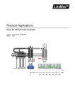
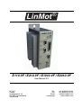
®
LinMot
E110-VF / E210-VF / E1010-VF / E2010-VF
User Manual 2.2
NTI AG
LinMot
Haerdlistrasse 15
CH-8957 Spreitenbach
Switzerland
Tel.:
Fax:
Email:
Homepage:
+41 (0)56 419 91 91
+41 (0)56 419 91 92
[email protected]
www.LinMot.com
© 2005 NTI AG
This work is protected by copyright.
Under the copyright laws, this publication may not be reproduced or transmitted in any form, electronic or mechanical, including photocopying, recording, microfilm, storing in an information retrieval system, not even for didactical use, or translating, in whole or in
part, without the prior written consent of NTI Ltd.
LinMot® is a registered trademark of NTI Ltd.
Note
The information in this documentation reflects the stage of development at the time of press and is therefore without obligation.
NTI Ltd. reserves itself the right to make changes at any time and without notice to reflect further technical advance or product
improvement. Please refer to the latest edition of our "General business terms"
Document version 8/ as, July 2005
Table of Contents
LinMot ®
1.
Description and Features ...................................................................................... 5
1.1 Description............................................................................................................. 5
1.2 Features .................................................................................................................. 5
2.
2.1
2.2
2.3
2.4
2.5
2.6
2.7
Theory of Operation .............................................................................................. 6
Servo Loops ........................................................................................................... 6
Amplifier Types ..................................................................................................... 6
Master/Booster Operation...................................................................................... 7
Safety ..................................................................................................................... 7
Position Measurement............................................................................................ 7
Referencing ............................................................................................................ 8
Protection circuits .................................................................................................. 8
3.
Installation.............................................................................................................. 9
3.1 Mechanical Dimensions of LinMot® Amplifiers ................................................... 9
3.2 Mechanical Installation of LinMot® Amplifiers .................................................. 10
3.3 Electrical Connection........................................................................................... 11
4.
LinMot® Commander .......................................................................................... 19
4.1 Installation of LinMot®-Commander................................................................... 19
4.2 Upgrading Amplifier Firmware ........................................................................... 19
4.3
Logging into LinMot® Amplifier......................................................................... 20
4.4
4.5
4.6
4.7
4.8
Starting and Stopping the LinMot® Amplifier..................................................... 20
Configuration ....................................................................................................... 21
Variables Monitoring ........................................................................................... 21
Oscilloscope......................................................................................................... 22
Messages .............................................................................................................. 23
5.
LinMot® Ex10-VF / Ex010-VF Parameters ....................................................... 24
5.1 System Parameters ............................................................................................... 24
5.2 Drive Parameters.................................................................................................. 25
6.
6.1
6.2
6.3
6.4
Amplifier Setup .................................................................................................... 33
Amplifier Mode ................................................................................................... 33
General Parameters .............................................................................................. 33
Force Control Mode ............................................................................................. 35
Velocity Control Mode......................................................................................... 36
A.
Operating States................................................................................................... 43
B.
Maintenance ......................................................................................................... 46
C. VF-Amplifier with ME01-Extension Module.................................................... 47
C.1 Wiring .................................................................................................................. 47
C.2 LED mimics ......................................................................................................... 47
Manual Ex10-VF / Ex010-VF V2.2
3
Table of Contents
Manual Ex10-VF / Ex010-VF V2.2
LinMot ®
4
Description and Features
LinMot ®
1. Description and Features
1.1 Description
The LinMot® E110-VF, E210-VF, E1010-VF and E2010-VF servo amplifiers
allow linear motors of the LinMot®-P series to be integrated very easily in
existing motion controller multi-axis systems. In addition single phase actuators like DC-Motors can be controlled with this amplifier.
• The integration of two independent drives into a single housing saves place
and minimizes wiring.
• Each amplifier channel accepts a bipolar DC control input. The amplitude of
this signal may be used to control either the velocity or the current (force) of
the connected LinMot® linear motor.
• Basing on the integrated sensors of a LinMot® linear motor, the actual position is available as incremental position signal (A/B).
• Each amplifier has several protection circuits to protect the amplifier, motor
and operator from almost any kind of fault. Flashing LED show the type of
fault occurred, and separate outputs can be used to send signals to other
equipment. In addition the error or warn message can be read in plain-text
by using the LinMot® Commander software.
1.2 Features
• Ergonomic design:
Easy configuration with Windows® based software
tools. Easy access to connections.
• Differential Inputs:
Two independent low noise differential inputs
accepting ±10VDC.
• Dual mode operation:
The amplifier may be configured for current (force)
or velocity control.
• Current Limit:
Maximum motor current is adjustable. Two different
levels can be selected with a digital input.
• Fault and Warn output: Two digital outputs per motor channel monitor the
status of the amplifier. Polarity of these signals can
be configured.
• Short circuit protection: Phase outputs are short circuit protected.
• LED diagnostics:
Green LED indicates normal operation condition,
yellow LED indicates warnings and red LED indicate fault conditions. The yellow LED flashes in
fault condition to display the actual fault.
• Over/under voltage:
These circuits monitor amplifier power-supply voltages constantly. They will shut down the amplifier in
the event of any out-of-specification condition.
• Over temperature:
The motor and the amplifier-heatsink temperature
is monitored constantly. The amplifier will be shut
down in case of over temperature.
Manual Ex10-VF / Ex010-VF V2.2
5
LinMot ®
Theory of Operation
2. Theory of Operation
2.1 Servo Loops
Most position control systems are arrangements of three control loops as
shown in Figure 2-1:
1 The current loop directly influences motor acceleration and deceleration
(force). The current loop is present in each amplifier.
2 The velocity loop supplies a velocity signal which becomes the demand
signal for motor acceleration. Some amplifiers give the user the possibility
to close the velocity loop inside the amplifier.
3 The position control loop is the over-riding motion loop. The position loop
is generally closed by a third party motion controller and can not be closed
inside the LinMot® VF-Amplifier. If the position loop must also be closed by
LinMot® then LinMot® standard controllers (AT, MT, DP or DN family) must
be used instead of VF-Amplifiers.
Motor
Command
Position loop
Velocity loop
x
v
Current loop
I
Position encoder
M
E
dx/dt
Position
Figure 2-1: Arrangement of the three essential loops for position control.
2.2 Amplifier Types
Different types of amplifiers are known. In motion control systems velocitymode and force-mode amplifiers are most used. LinMot® VF-Amplifiers can
be configured to operate in both of these modes.
Velocity Loop Operation
In this operation mode the two inner loops, the current loop and the velocity
loop, are closed in the amplifier. The input signal of the amplifier is the
demand velocity of the connected motor.
Because the velocity loop tuning is load dependent, the velocity-loop of an
amplifier must be tuned before the position loop is closed with an external
position controller. Chapter 6 describes how to tune the velocity-loop of a LinMot® amplifier.
Current Loop Operation
In this operation mode only the current loop is closed in the amplifier. The
input signal of the amplifier represents the demand force of the connected
motor. The current loop on most amplifiers, also the LinMot® amplifiers, is
already tuned at factory and doesn’t need to be tuned by the user.
6
Manual Ex10-VF / Ex010-VF V2.2
LinMot ®
Theory of Operation
2.3 Master/Booster Operation
Master/Booster operation enables the force available for a movement to be
increased by putting motors in series or parallel. One motor must be defined
as master, the other as booster. The moving part of the motors must be coupled mechanically.
During operation all parameters for the booster motor are copied from the
master motor. The current is calculated for the master motor only and set for
both motors.
A booster motor may work in the same or in the opposite direction as the master. This behavior can be chosen by selecting the type of actor.
Master
Master
Booster reverse
Booster parallel
Figure 2-2: Master/Booster operating mode
2.4 Safety
LinMot® amplifiers will energize the motors only if no error is pending and the
Enable Input is activated.
To ensure that the motors do not “jump” when the Enable Input gets activated
the analog input signal (demand force or demand velocity) must be about 0V
at this moment. For safety reasons the controller can deny a transition to RUN
state if this signal is not in the range -1V..1V. This safety feature is disengageable.
For a safe operation of linear motion-systems, motions in the end range of the
allowed stroke must be monitored specially. This is normally done with limitswitches at both ends of the stroke. If the drive is moved into one of this
switches the drive must be stopped immediately. The limit switch signals must
be fed into the superior motion controller.
2.5 Position Measurement
The accuracy of motion systems depends mainly on the implemented position
measurement system.
LinMot® linear motors have integrated position sensors basing on the measurement of the magnetic field of the slider. This method allows a position
repeatability better than 0.1mm. The LinMot® Ex10-VF and Ex010-VF amplifier family outputs this information as quadrature (A/B) signal.
The resolution of this simulated encoder outputs can be configured to 1µm,
2µm, 5µm, 10µm, 20µm or 50µm (4x sampling). Choosing a higher resolution
does not increase the accuracy because the encoder simulation always works
basing on the internal sensor system with the given repeatability.
The incremental position outputs can provide frequencies up to 3MHz. This
limits the max. velocity depending on the chosen resolution (3m/s @ 1µm). If
Manual Ex10-VF / Ex010-VF V2.2
7
LinMot ®
Theory of Operation
the encoder rate is too high a warning is issued. Position increments could be
lost if the allowed rate is exceeded.
Position accuracy can be increased by using an external position sensor
(incremental linear encoder) connected directly to the superior position controller. With high-end encoders, a position repeatability better than 1µm can
be realized.
If the VF-Amplifier is equipped with an ME01 Extension Module then the signal from an external position sensor can be used for position control (superior
motion controller) and speed control (VF-Amplifier in velocity mode). See
Appendix C.
The external sensor system MS01 which is used for the LinMot® standard
controllers (AT, MT, DP and DN) can not be used with the VF-Amplifier.
2.6 Referencing
Most linear positioning system, including the LinMot® system, are based on
incremental position measurement. A special reference sequence is necessary to define a reference position.
This reference search must be accomplished by the superior position control
system. LinMot® actuators can be referenced against a hard stop which will
cause no harm to the motor.
2.7 Protection circuits
LinMot® amplifiers monitor all important operation parameters like supply and
temperature constantly. Any anormality will lead to a warning or error.
A warning is issued and signaled with the Warn Output when any of the monitored parameters is in a critical range. The warning is cleared after the
parameters are back in a save range. The warning signal can be used by the
superior controller to move the motor to a save position before disabling.
An error will shut down the amplifier if one of the monitored parameters is in
an out-of-specification range. The ERROR state of the drive can only be left if
all parameters are back in normal operation range and the Enable Input is
inactive.
8
Manual Ex10-VF / Ex010-VF V2.2
LinMot ®
Installation
3. Installation
3.1 Mechanical Dimensions of LinMot® Amplifiers
The LinMot® Ex10-VF amplifiers do have the same mechanical dimensions
as all other LinMot® standard controllers (AT, MT, DP or DN controllers) from
the 100series. The mechanical dimensions of the Ex010-VF amplifiers correspond with the standard 1000series controllers.
Fixings for
2 x M5 screws
179
Fixings for
2 x M5 screws
®-E2010
LinMot
120
Centers
315
®-E210
LinMot
330
Centers
195
295
210
175
56
Dimensions in mm
64
70
Dimensions in mm
90
Figure 3-1: Mechanical dimensions of the LinMot® amplifiers
Manual Ex10-VF / Ex010-VF V2.2
9
LinMot ®
Installation
3.2 Mechanical Installation of LinMot® Amplifiers
LinMot® amplifiers can be mounted with two screws (scew diameter 5mm,
max. head diameter 10mm) on a panel. The LinMot® amplifiers must be
mounted vertical to ensure good cooling.
For space requirements please see the following drawings.
Fixings for
2 x M5 screws
100
®
LinMot
®
LinMot
Maximal power
dissipation:
-E210
-E210
E110-VF 22W
E210-VF 38W
-E210
LinMot
®
100
50
50
50
100
50
Dimensions in mm
Figure 3-2: Installation of Ex10-VF amplifier
Fixings for
2 x M5 screws
100
®
LinMot
®
LinMot
®
LinMot
-E2010
-E2010
-E2010
100
Maximal power
dissipation:
E1010-VF 55W
E2010-VF 95W
50
50
50
100
Dimensions in mm
50
Figure 3-3: Installation of Ex010-VF amplifier
10
Manual Ex10-VF / Ex010-VF V2.2
LinMot ®
Installation
3.3 Electrical Connection
This chapter provides the information to make all the necessary electrical
connections to the amplifier.
Grounding
IMPORTANT: The housing of the LinMot® amplifiers must be earth grounded.
The ground of the power supplies must also be connected to earth at the
same single point. In order to prevent any harm to the system the motion controller has to be grounded to the same level. Both, the LinMot® amplifier and
the motion controller, must be connected to ground first before any other connections between them are installed.
I/O Connector
All I/O signals are available on the 25pin Sub-D style connector.
Connector: Sub-D25 female.
Pin
Function
Pin
Function
1
Drive A: Analog In+
14
Drive B: Analog In+
2
Drive A: Analog In-
15
Drive B: Analog In-
3
Analog GND
16
Analog GND
4
Drive A: Enable In
17
Drive B: Enable In
5
Drive A: Current Limit In
18
Drive B: Current Limit In
6
Drive A: Fault Out
19
Drive B: Fault Out
7
Drive A: Warn Out
20
Drive B: Warn Out
8
+6V .. +24V DC I/O Supply
21
I/O GND
9
Drive A: Encoder Out A+
22
Drive B: Encoder Out A+
10
Drive A: Encoder Out A-
23
Drive B: Encoder Out A-
11
Drive A: Encoder Out B+
24
Drive B: Encoder Out B+
12
Drive A: Encoder Out B-
25
Drive B: Encoder Out B-
13
GND Position Outputs
Table 3-1: Pin configuration of the Exx10-VF I/O connector
Analog Control Inputs
The analog control output of the motion controller and the input of the amplifier should be connected by a shielded cable to reduce noise pick-up. For a
higher noise immunity the analog inputs are symmetrical. The control voltage
is measured between the “Analog In+” and the “Analog In-” terminal. To avoid
ground loops the analog grounds of the motion controller and the amplifier
should not be connected together.
If the motion controller provides symmetrical outputs, noise pick-up is eliminated mostly. The output voltage of some motion controllers (i.e. Delta-Tau PMAC) must be limited to ±10V DC between the positive and negative output.
Manual Ex10-VF / Ex010-VF V2.2
11
LinMot ®
Installation
The following figure shows the wiring of the analog control signals for drive A:
Motion controller with asymetrical outputs
Controller
E210-VF
Out
1
GND
2
3
Motion controller with symetrical outputs
Controller
E210-VF
Out+
1
Out-
2
3
GND
Figure 3-4: Analog control signal wiring
Technical data of analog inputs:
Resolution:
Input voltage:
abs. max. rating:
Impedance:
12Bit
-10V DC .. +10V DC
-20V DC .. +20V DC
38kΩ
Digital I/O Signals
All digital I/O signals are optically isolated and can be operated between 5V
and 24V DC.
Digital outputs are built through overload protected high-side switches. The
output drivers must be supplied externally. The logic high level of the digital
outputs can be 2V less than the I/O supply voltage, depending on the load.
The outputs are equipped with weak pull-down resistors internally. The
required supply current depends on the load on the outputs.
Technical data of digital inputs:
Voltage:
0 .. 24V DC (abs. max. rating: -5 .. +28V DC)
for logic low:<2V
for logic high:>4V
<20mA
Current:
Technical data digital outputs:
I/O supply voltage:
Output voltage:
max. sourcing current:
Pull-down resistors:
max. sinking current:
6..28V DC
0..28V DC (depends on external supply)
0.5A
22kΩ
10mA @ 24V
The following figure shows a typical wiring of digital I/O signals for drive A:
Digital I/O Signals
Controller
E210-VF
Enable out
4
GP output
5
Fault in
6
GP input
7
Supply in
8
GND
21
+ I/O Supply
Figure 3-5: Digital I/O signal wiring
12
Manual Ex10-VF / Ex010-VF V2.2
LinMot ®
Installation
Simulated Position Encoder Outputs
The actual position of a LinMot® linear motor is available as an incremental
quadrature signal on the Sub-D 25 connector. As electrical interface the
RS422 / 5V standard is used.
Quadrature Signals (only Motor A shown)
Controller
E210-VF
Encoder A+
9
Encoder A-
10
Encoder B+
11
Encoder B-
12
Encoder GND
13
Figure 3-6: Wiring of position signals (Channel A shown)
If a single phase actuator (DC motor, voice coil) is connected to a motor channel then the respective simulated encoder outputs of the amplifier must not be
used. In this case the actuators position sensor is directly connected to the
superior motion control system.
Also if a LinMot® linear axis is equipped with a high accurate external position
sensor, the simulated encoder outputs must not be used. The superior motion
controller uses directly the external position sensor signals in this case.
Serial Communication Interface
The serial communication interface is used to configure the LinMot® Ex10-VF
and Ex010-VF amplifiers. It can be directly connected to the RS232 port of
any PC. Take care not to use a crossed (0-Modem) cable, but a cable connecting Pins 2,3 and 5 one to one.
Connector: Sub-D 9, male
Pin
Function
Pin
Function
1
do not connect
6
do not connect
2
RS232_TX
7
do not connect
3
RS232_RX
8
do not connect / CAN_L
4
do not connect
9
do not connect / CAN_H
5
GND
Table 3-2: Pin configuration on the Exx10-VF Com connector
Power Supply
Power supply inputs for signal electronics and motors are separated on both,
the LinMot® Ex10-VF and Ex010-VF amplifiers. On machines whose actuators must be powered off in the event of an emergency shutdown for safety
reasons, the motor supply can be switched off. By maintaining the signal supply, the position of the motor can still be captured.
Manual Ex10-VF / Ex010-VF V2.2
13
LinMot ®
Installation
CAUTION: Exceeding the given absolut maximal rating voltages will harm the
VF-Amplifier and the connected motors as well.
Power supplies must be switched on and off on their primary side only.
Ex10-VF
Ex10-VF amplifiers are supplied via a single three-pole connector:
matching socket: Phoenix PSC 1.5/3-F
Pin
Function
Nominal Voltage
Abs. max. rating
1
+Vcc signal supply
+24V .. +48V DC
+55V
2
Ground
GND
-
3
+Vcc motor supply
+24 V.. +48V DC
+55V
Table 3-3: Pin configuration of the Ex10-VF PWR socket
LinMot ®-E210
LinMot ®-E210
Mot A
Mot A
Supply
24 ... 48V DC
Mot B
Mot B
Com
Com
PWR
PWR
+
-
Figure 3-7: Supply wiring of Ex10-VF
Ex010-VF
The Ex010-VF amplifier is supplied via two separate connectors.
Signal electronics are supplied by a three-pole connector:
matching socket: Phoenix PSC 1.5/3-F
Pin
Function
Nominal voltage
Abs. max. rating
1
+Vcc signal supply
+24V..+48V DC
+55V
2
Ground
GND
GND
3
do not connect
Table 3-4: Pin configuration on Ex010-VF PWR Signal socket
14
Manual Ex10-VF / Ex010-VF V2.2
LinMot ®
Installation
Motors are supplied via a two-pole connector:
matching socket: Phoenix MSTB 2,5/2-STF
Pin
Function
Nominal voltage
Abs. max. rating
top
Ground
GND
-
bottom
+Vcc motor supply
+48V..+72V DC
+80V
Table 3-5: Pin configuration on Ex010-VF PWR Motor socket
LinMot ®-E2010
LinMot ®-E2010
Mot A
Mot A
Mot B
Mot B
Signalsupply
24 ... 48 V DC
Motorsupply
48 ... 72 V DC
+
+
-
Com
-
Com
PWR
PWR
Motor
Motor
Signal
Signal
Figure 3-8: Supply wiring of Ex010-VF
Motor Connection
The actuator cables are plugged into the connectors found on the front panel
of the amplifier marked as MOT A and MOT B. All necessary signals for one
motor are integrated in a single connector.
CAUTION: Incorrect connection of the actuators may lead to destruction of
the amplifier and the motors. Disconnecting/reconnecting motors while the
amplifier is powered on (even in DISABLE state) can damage the motor and
the amplifier.
For extension cables original LinMot® cables must be used only.
Neither the LinMot® motor cables nor the standard LinMot® extension cables
K01 are flex-cables. Wherever the active part of the motor (stator) is not fixed
the special trailing chain cable KS01 has to be used.
Manual Ex10-VF / Ex010-VF V2.2
15
LinMot ®
Installation
LinMot® Linear Motors
Ex10-VF
LinMot® linear motors are connected via 9-pin D-Sub sockets to an Ex10VF amplifier.
Pin
Color
Signal
1
red
phase 1+
2
blue
3
Pin
Color
Signal
6
pink
phase 1-
phase 2+
7
grey
phase 2-
white
+5V
8
brown
ground (GND)
4
yellow
sine sensor
9
green
cosine sensor
5
black
temp. sensor
Table 3-6: Pin configuration for the Ex10-VF motor socket
Ex010-VF
LinMot® linear motors are connected via 10-pin Mini-Combicom sockets to
an Ex010-VF amplifier.
Pin
Color
Signal
Pin
Color
Signal
1
red
phase 1+
6
brown
ground (GND)
2
pink
phase 1-
7
yellow
sine sensor
3
blue
phase 2+
8
green
cosine sensor
4
grey
phase 2-
9
black
temp. sensor
5
white
+5V
-
shielding
10
Table 3-7: Pin configuration for the Ex010-VF motor socket
Single Phase Actuators
Single phase actuators like DC-Motors or Voice Coils must be connected
to phase 1 of the corresponding motor output. Their position sensor signals must be connected to the superior motion controller.
On phase 2 of the motor output a bleeder resistor can be connected. Rotative DC-Motors tend to bring a lot of energy into the amplifiers DC link during deceleration. The back EMF can increase the DC link voltage over the
maximum allowed limits (55V for Ex10-VF and 80V for Ex010-VF amplifiers) which leads to a transition to ERROR state. When the DC link voltage
exceeds (in parameter tree definable) bleeding voltage the amplifier
begins to bleed off power over this external brake resistor.
The optional bleeder must have resistance according to the following
table. The brake resistor should be able to draw 100W out of the DC link.
Motor Power Supply
Ex10-VF
Ex010-VF
24V
8Ω
-
48V
16Ω
8Ω
72V
-
12Ω
Table 3-8: Recommended bleeder resistance values
For single phase actuators no other than the current output pins on the
amplifiers motor socket must be used.
16
Manual Ex10-VF / Ex010-VF V2.2
LinMot ®
Installation
.
Ex10-VF
Pin
Signal
Pin
Signal
1
motor phase +
6
motor phase -
2
optional bleeder phase+
7
optional bleeder phase -
3
do not connect
8
do not connect
4
do not connect
9
do not connect
5
do not connect
Table 3-9: Pin configuration for single phase actuators on LinMot®
Ex10-VF motor socket
Ex010-VF
Pin
Signal
Pin
Signal
1
motor phase +
6
do not connect
2
motor phase -
7
do not connect
3
optional bleeder phase +
8
do not connect
4
optional bleeder phase -
9
do not connect
5
do not connect
10
do not connect
Table 3-10: Pin configuration for single phase actuators on LinMot®
Ex010-VF motor socket
Typical System Wirings
The following figures show the typical system wiring for drive A on a VFAmplifier. Drive B is wired similarly.
The system consists of the following components:
• Motion controller
• LinMot® Ex10-VF amplifier
• LinMot® power supply
• Actuator: LinMot® linear motor with or without external position sensor.
• 6V .. 24V supply for I/O signals and motion controller
Manual Ex10-VF / Ex010-VF V2.2
17
LinMot ®
Installation
Wiring of an Ex010-VF amplifier would be the same except for the extra motor
power supply (48V..72V).
MOTION CONTROLLER
LinMot® Ex10-VF
ENCODER VCC
ENCODER GND
ENCODER IN A+
ENCODER IN AENCODER IN B+
ENCODER IN B-
13: ENC. GND
9: ENC. OUT A+
10: ENC. OUT A11: ENC. OUT B+
12: ENC. OUT B-
ANALOG OUT +
ANALOG OUT ANALOG GND
1: ANALOG IN +
2: ANALOG IN 3: ANALOG GND
AMP. ENABLE
GP OUT
AMP. FAULT
GP IN
4: ENABLE IN
5: C. LIMIT IN
6: FAULT OUT
7: WARN OUT
SUPPLY
IO GND
8: VCC EXT. IO
21: IO GND
MOT A
PWR SIGNAL
GND
PWR MOTOR
PSU LinMot®
PSU MC
+6V.24V DC
GND
+24V..48V DC
GND
Figure 3-9: Typical system wiring using the internal position measuring
system of LinMot® linear motors
MOTION CONTROLLER
LinMot® Ex10-VF
ENCODER VCC
ENCODER GND
ENCODER IN A+
ENCODER IN AENCODER IN B+
ENCODER IN B-
13: ENC. GND
9: ENC. OUT A+
10: ENC. OUT A11: ENC. OUT B+
12: ENC. OUT B-
ANALOG OUT +
ANALOG OUT ANALOG GND
1: ANALOG IN +
2: ANALOG IN 3: ANALOG GND
AMP. ENABLE
GP OUT
AMP. FAULT
GP IN
4: ENABLE IN
5: C. LIMIT IN
6: FAULT OUT
7: WARN OUT
SUPPLY
IO GND
8: VCC EXT. IO
21: IO GND
PSU MC
+6V..24V DC
GND
MOT A
PWR SIGNAL
GND
PWR MOTOR
PSU LinMot®
+24V..48V DC
GND
Figure 3-10: Typical system wiring using an external position sensor.
With high-end encoders a position repeatability better than 1µm can be
realized.
18
Manual Ex10-VF / Ex010-VF V2.2
LinMot®
LinMot ®
Commander
4. LinMot® Commander
The LinMot® Ex10-VF and Ex010-VF servo amplifiers are full digital controlled devices. They must be configured during the first commissioning. This
is done with the Windows-based LinMot®-Commander.
Before starting make sure that the amplifier is powered and the serial interface is connected to the PC with a one to one serial cable (female connectors
on both ends).
4.1 Installation of LinMot®-Commander
The new LinMot®-Commander software is a 32bit Windows® software. It
runs on computers operating under Windows® 95, 98, NT4.0, 2000, ME
and XP.
The actual software release (V 2.2.x) is available from the LinMot® home
page www.linmot.com. After downloading the software you can start
“setup.exe” and follow the instructions in order to install the whole software
package on your computer.
The program can be started by clicking “Start” → “Programs” → “LinMot” →
“LinMot® Commander 2.2.x”.
4.2 Upgrading Amplifier Firmware
It is recommended to download the latest firmware version to the amplifier
(V2.2.x). Downloading firmware will erase an eventually existing old configuration and will reset all parameter tree items to their default values.
Start LinMot®-Commander, but don’t log in. Start the installation script by
clicking the “Run Script” button
:
Figure 4-1: Starting the firmware download script
In the file dialog select the new firmware installation file “Lm2R2Rx.sct” from
folder “Cmdr2r2r0\Firmware\Lm2R2Rx\”. In the upcoming window the serial
port which is used for updating the amplifier must be selected.
Manual Ex10-VF / Ex010-VF V2.2
19
LinMot ®
LinMot® Commander
Figure 4-2: Successful download of all firmware components
After successful installation close the “Package Installer” window.
4.3 Logging into LinMot® Amplifier
To start the communication with a LinMot® amplifier connected to the
serial port of your PC a login procedure is necessary. This can be done by
opening the “File” menu and selecting “Login” or double-clicking on
“Project”.
In the upcoming dialog window the communication port can be selected.
There can be only one LinMot® amplifier per serial port, but simultaneous
communications with additional LinMot® amplifiers on different serial-ports
is possible. Leave the password field empty.
After successful login all features of the LinMot® amplifier can be accessed
in a tree structure, similar to the Windows® file explorer.
4.4 Starting and Stopping the LinMot® Amplifier
To set some configuration parameters, the software running on the amplifier must be stopped in advance (there will be a message dialog if it is necessary to stop the software). This can be done by clicking the “STOP”
button shown in the picture below.
Disable the servo loop on the superior controller and wait until the connected motors stand still before stopping the amplifier software.
The “STOP” button will change to a “START” button when the amplifier
software is stopped. Press this button to restart normal operation of the
LinMot® amplifier.
20
Manual Ex10-VF / Ex010-VF V2.2
LinMot®
LinMot ®
Commander
4.5 Configuration
All configuration parameters can be found under the “Configuration” folder.
The parameters are arranged in a tree-structure. In the left pane the
parameter group is chosen, on the right pane its value can be set.
Figure 4-3: Editing of VF-Amplifier configuration
All changes in the parameter settings are automatically copied into the non
volatile memory of the amplifier. Some parameters can only be set if the
software running on the LinMot® amplifier is stopped. So called Live
Parameters (tagged with a superscript red L) can be altered during run
time. E.g. the controller gain parameters are live parameters therefore the
loop tuning can be done online.
Some parameters are visible only under certain circumstances. E.g. the
user doesn’t have the opportunity to configure Velocity Mode if Actuator
Type is set to Single Phase Actuator.
Drive A and B are configured independent from each other (except for
Master/Booster operation). Parameters which affects the whole VF-Amplifier can be found in the \Information and \System folders.
4.6 Variables Monitoring
In the “Variables Monitoring” folder important variables of the system and
each drive can be monitored.
Figure 4-4: Variables Monitoring feature
Read Variable: By clicking on this button the value of the selected
variable will be updated.
Read All Variables: All variables listed in the right pane will be
updated.
Manual Ex10-VF / Ex010-VF V2.2
21
LinMot ®
LinMot® Commander
The updated values are valid only if the controller software has been running while the “Read” button has been pressed (the red “Stop” button is
visible in this case).
4.7 Oscilloscope
Figure 4-5: LinMot® Commander software oscilloscope
The LinMot®-Commander software oscilloscope is a very helpful tool for
commissioning a LinMot® drive system. The buttons in the Oscilloscope
pane do have the following functionality:
Setting: After pressing this button the user can do the setting for his
measurements: Choosing the variables to be observed, setting the
recording time, defining trigger conditions and setting different display
options.
Start: If no trigger condition is set the recording of the selected variables immediately begins after pressing the start button. If additional
trigger conditions are defined then the controller starts the measuring the
first time the conditions are fulfilled.
Fit View: The “Fit View” feature automatically sets scale and offset
of the oscilloscope display in order to show all recorded data in the
display window.
Zoom in/out: Instead of adjusting the offset and scale manually
(Setting window) in order to see some data more in detail the
zoom functions may be used.
Export: The measured data can be saved to disk in Comma Separated Values (csv) format for further evaluation (e.g. with MS Excel,
Matlab etc.).
22
Manual Ex10-VF / Ex010-VF V2.2
LinMot®
LinMot ®
Commander
4.8 Messages
The amplifier monitors the drive operational states and all critical parameters constantly. If one of them is out of the specification range a warning or
an error message is generated and signalled to the superior control with
digital I/O signals.
The LinMot® amplifiers stores events internally with a time stamp (state
transitions, warnings, errors). Warnings and errors enabled in the Logging
mask are also stored in the nonvolatile memory. With the LinMot® Commander Message-Service the events stored and logged in a LinMot®
amplifier can be viewed in plain text.
Figure 4-6: Observing state transitions and warning/error events with
the Messages tool
The messages stored in the nonvolatile memory are marked with
“(logged)”.
Manual Ex10-VF / Ex010-VF V2.2
23
LinMot ®
LinMot® Ex10-VF / Ex010-VF Parameters
5. LinMot® Ex10-VF / Ex010-VF Parameters
In this chapter you will find short descriptions of the configuration parameters.
Following signs are used in the tables below:
Read-only parameter, user cannot alter this parameter.
Live parameter, this parameter can be altered during operation.
This symbol indicates that the parameter is visible only under certain circumstances.
5.1 System Parameters
DCLV Monitoring
In this folder the DC link voltage levels which can generate warnings and
errors are defined. Exceeding the ranges will activate the Warn Output and
the Error Output if the corresponding items in the drive specific Warn and
Error Detection Mask are selected (see below).
\Configuration\System\DCLV Monitoring
24
Motor supply low
warn
When the motor supply voltage sinks below this level
(default 21V for Ex10-VF, 42.2V for Ex010-VF) the
warning condition is fulfilled.
Motor supply
high warn
When the motor supply voltage exceeds this level
(default 50.6V for Ex10-VF, 76.3V for Ex010-VF) the
warning condition is fulfilled.
Motor supply low
error
When the motor supply voltage sinks below this level
(default 18.2V for Ex10-VF, 36.5V for Ex010-VF) the
fault condition is fulfilled.
Motor supply
high error
When the motor supply voltage exceeds this level
(default 53.4V for Ex10-VF, 79.6V for Ex010-VF) the
fault condition is fulfilled.
Signal supply low
warn
When the motor supply voltage sinks below this level
(default 21V) the warning condition is fulfilled.
Signal supply
high warn
When the motor supply voltage exceeds this level
(default 50.6V) the warning condition is fulfilled.
Signal supply low
error
When the motor supply voltage sinks below this level
(default 18.2V) the fault condition is fulfilled.
Signal supply
high error
When the motor supply voltage exceeds this level
(default 53.4V) the fault condition is fulfilled.
Manual Ex10-VF / Ex010-VF V2.2
LinMot®
Ex10-VF / Ex010-VF Parameters
LinMot ®
5.2 Drive Parameters
Motor Type
This parameter defines the type of the connected actuator.
\Configuration\Drive x\Motor type
No motor
no actuator connected
LinMot P0x-23
LinMot® Motor of the P0x-23 family
LinMot P0x-37
LinMot® Motor of the P0x-37 family
Single phase
actuator
Single phase actuator like DC-Motors, Voice-CoilMotors or Magnets
Parallel Booster
Motor B is a booster working in the same direction as
motor A.
1)
Reverse Booster
1)
Motor B is a booster working in the opposite direction
as motor A.
1) Visible only for drive B and only if drive A motor type is LinMot P0x
Amplifier Setup
In this folder the amplifier mode and control parameters are set. For further
description of the controller loops see chapter 6.
Amplifier Mode
With the Amplifier Mode parameter the user can select which servo-loops
are closed inside the LinMot® amplifier.
\Configuration\Drive x\Amplifier setup\Amplifier mode
Force
Only the current loop is closed inside the amplifier.
The output current is proportional to the analog command signal.
Velocity
The current and velocity loops are closed inside the
amplifier. The velocity of the connected linear motor
is proportional to the analog command signal.
1)
1) Visible only if motor type is LinMot P0x
Manual Ex10-VF / Ex010-VF V2.2
25
LinMot ®
LinMot® Ex10-VF / Ex010-VF Parameters
Control Parameters
Depending on the selected amplifier mode different control parameters
can be set.
\Configuration\Drive x\Amplifier setup\Control parameters
Maximum current
Sets the maximum current applied to the motor. This
parameter also determines the maximum force the
motor can provide. Maximal current also depends on
the motor type and supply voltage.
Unit: A
Current offset
Offset current used to compensate static forces such
as gravity in vertical applications.
Unit: A
Current limit (CL
Input)
Set the maximal current applied to the motor when
the Current Limit input is active.
Unit: A
Current gain
1)
Ratio between input voltage and output current
(demand motor current at +10V input).
Unit: A
Velocity gain
2)
Ratio between input voltage and demand velocity
(demand velocity at +10V input).
Unit: m/s
P-Gain velocity
loop
2)
Determines how the difference between demanded
velocity and actual velocity is represented by current
command value.
Unit: A/(m/s)
I-Gain velocity
loop
2)
FF Acceleration
2)
Determines how the time integral of velocity deviation
is represented by the current.
Unit: A/(m/s)/s
Determines which current must be fed forward to
obtain the desired acceleration.
Unit: A/(m/s^2)
FF Friction
2)
Determines which current must be fed forward to
compensate dry friction.
Unit: A
1) Visible only if the force mode is selected.
2) Visible only if the velocity loop is closed in the LinMot® amplifier.
26
Manual Ex10-VF / Ex010-VF V2.2
LinMot®
Ex10-VF / Ex010-VF Parameters
LinMot ®
Advanced Settings
The parameters in the Advanced Setting folder may be modified only by
advanced users with expert knowledge in control theory.
\Configuration\Drive x\Amplifier setup\Advanced settings
Analog In offset
With this parameter an offset to the analog command
input can be added or subtracted.
Unit: V
FF Acceleration
dead band
1)
Currents caused by the FF Acceleration network
smaller than this value are suppressed. Noise introduced by derivation of the demand speed signal can
be reduced with this parameter.
Unit: A
FF Friction dead
band
1)
The FF Friction network does fully affect the controller output only if the analog command input (demand
velocity) is greater than this value (noise suppression
while standstill of the motor).
Unit: V
Actual speed
dead band
1)
If the actual speed is less than this value then the
actual speed is set to zero. Noise introduced by derivation of the actual position can be reduced with this
parameter (noise suppression while standstill of the
motor).
Unit: m/s
Integrator limit
1)
This value limits the velocity control loop integrator
capacity. The demand current part caused by the IGain is limited in order to suppress position over
shoots.
Unit: A
Bleeder voltage
2)
If the motor supply DC link voltage exceeds this level
the amplifier begins to bleed off power over the
optional external brake resistor.
Unit: V
1) Visible only if the velocity loop is closed in the LinMot® amplifier.
2) Visible only if Single Phase Actuator is selected.
Manual Ex10-VF / Ex010-VF V2.2
27
LinMot ®
LinMot® Ex10-VF / Ex010-VF Parameters
Position Capturing
When high performance in the position control is required then the LinMot®
linear motor axis has to be equipped with an additional external position
sensor. The signals of this sensor are used from the superior motion control system for closing the position control loop. If the LinMot® VF-Amplifier
is equipped with an ME01 extension module the same external sensor signals can also be used for position and speed capturing in the LinMot® VFAmplifier. This makes sense only for axes in velocity control mode. See
also Appendix C.
If the VF-Amplifier is not equipped with a ME01 extension module (as
usual) the “Internal sensor” check box must be selected.
.
\Configuration\Drive x\Position capturing
Internal sensor
1)
External AB
encoder 1um
2)
External AB
encoder 2um
2)
External AB
encoder 5um
2)
External AB
encoder 10um
2)
External AB
encoder 20um
2)
Position capturing based on the internal position
measuring system. If no ME01 extension module is
used this item must be checked.
Position capturing based on an external AB linear
encoder with 1µm resolution connected to the ME01
extension module.
Position capturing based on an external AB linear
encoder with 2µm resolution connected to the ME01
extension module.
Position capturing based on an external AB linear
encoder with 5µm resolution connected to the ME01
extension module.
Position capturing based on an external AB linear
encoder with 10µm resolution connected to the ME01
extension module.
Position capturing based on an external AB linear
encoder with 20µm resolution connected to the ME01
extension module.
1) This parameter is only visible if a LinMot® linear motor type is selected.
2) Visible only if the velocity loop is closed in the LinMot® amplifier.
28
Manual Ex10-VF / Ex010-VF V2.2
LinMot®
Ex10-VF / Ex010-VF Parameters
LinMot ®
Encoder Simulation
This parameter sets the resolution of the simulated encoder output signals.
The encoder simulation is always based on the internal position measuring
system of the LinMot® linear motor. The max. speed depends on the
selected resolution. If this value is exceeded a warning is generated.
\Configuration\Drive x\Encoder simulation
1um
1)
2um
Position is put out in 1µm increments
max. speed: 2.5m/s
1)
Position is put out in 2µm increments
max. speed: 5m/s
5um
Position is put out in 5µm increments
1)
10um
Position is put out in 10µm increments
1)
20um
Position is put out in 20µm increments
1)
50um
Position is put out in 50µm increments
1)
1) This parameter is only visible if a LinMot® linear motor type is selected.
I/O Logic Definition
These parameters modify the active level of the digital I/O signals.
\Configuration\Drive x\I/O logic definition
Invert Enable In
If this parameter is checked, the Enable Input
becomes low active.
Invert CL In
If this parameter is checked, the Current Limit (CL)
Input becomes low active.
Invert Fault Out
If this parameter is checked, the Fault Output is set
high during normal operation and low when the drive
is in ERROR state.
Invert Warn Out
If this parameter is checked, the Warn Output is set
high during normal operation and low in the case of a
pending warning.
Manual Ex10-VF / Ex010-VF V2.2
29
LinMot ®
LinMot® Ex10-VF / Ex010-VF Parameters
Errors and Warnings
The LinMot® amplifier firmware constantly monitors all important operation parameters. Deviations from save operation state are indicated to the
superior control system with digital outputs (Warn and Fault output).
Error Detection Mask
With the Error Detection Mask the user can decide which internal error
conditions lead to ERROR state transition (motor will be switched off, Fault
Out activated and a respective error message generated).
\Configuration\Drive x\Position capturing\Errors and Warnings\Error
detection mask
Motor type mismatch
This error is set if the connected motor type does not
match with the selection in the parameter tree.
Slider missing
This error is set if the amplifier can’t detect a slider in
the LinMot® linear motor stator.
1)
Amplifier thermal overload
The temperature of the power electronics in the
amplifier is monitored constantly. If the VF-Amplifier is too hot it will shut down.
Motor overload
(calculated)
Based on the output current the amplifier estimates
the actual motor temperature. If the motor is too hot
calculated this error is set. With this feature crash
situations can be detected faster than with the
hardware sensor. This item should be deselected
only if this error occurs sometimes during normal
operation (no crashes). The motor is then running
near its thermal limit.
1)
Motor overload
(temp sensor)
1)
30
LinMot® linear motors are equipped with integrated
temperature sensors. If a connected motor gets too
hot this error is set and the motor channel is switched
off.
Signal supply too
low
If the signal supply voltage sinks below the defined
level2) the drive is shut down.
Signal supply too
high
If the signal supply voltage rises over the defined
level2) the drive is shut down.
Motor supply too
low
If the motor supply voltage sinks under the minimal
specified level2) the drive is shut down.
Manual Ex10-VF / Ex010-VF V2.2
LinMot®
Ex10-VF / Ex010-VF Parameters
LinMot ®
\Configuration\Drive x\Position capturing\Errors and Warnings\Error
detection mask
Motor supply too
high
If the motor supply voltage rises over the maximal
specified level2) the drive is shut down.
External position
sensor error
External position sensor is not available. The ME01
module not supplied or not existent at all. With a
ME01-01/08 module an external position sensor is
available only on channel A.
3)
Master/Booster
error
An error on the booster leads to ERROR state on
the master motor.
4)
Start permission
error
The transition to RUN state is denied if analog
command input is not in the range of -1V..+1V
when enable input becomes activated.
1) This parameter is visible only if a LinMot® linear motor type is selected.
2) The level can be set at \Configuration\System\DCLV Monitoring
3) This parameter is visible only if the usage of an external AB encoder is selected.
4) This parameter is visible only on Drive A if Motor Type of Drive B is set to be a Booster
motor.
Warn Detection Mask
With the Warn Detection Mask the user can decide which internal warn
conditions activate the Warn Output and generate a warn message.
\Configuration\Drive x\Position capturing\Errors and Warnings\Warn
detection mask
Motor overload
(calculated)
1)
Motor overload
(temp sensor)
1)
Based on the output current the amplifier estimates
the actual motor temperature. If the estimated temperature becomes high a warning is generated.
LinMot® linear motors are equipped with integrated
temperature sensors. If a connected motor gets hot
this warning occurs some seconds before the axis
goes to the ERROR state.
Signal supply low
If the signal supply voltage sinks below the defined
level2) a warning is generated.
Signal supply
high
If the signal supply voltage exceeds the defined
level2) a warning is generated.
Motor supply low
The amplifier generates a warning if the motor supply voltage sinks under the defined warn level2).
Motor supply
high
The amplifier generates a warning if the motor supply voltage rises over the defined warn level2).
Encoder output
frequency high
This warning is activated if the encoder rate is near
the limit (3 MHz)
1) This parameter is visible only if a LinMot® linear motor type is selected.
2) The level can be set at \Configuration\System\DCLV Monitoring
Manual Ex10-VF / Ex010-VF V2.2
31
LinMot ®
LinMot® Ex10-VF / Ex010-VF Parameters
Error / Warn Logging Mask
These masks determine which errors and warnings are logged in the non
volatile memory of the LinMot® amplifier. Only errors and warnings which
are selected in the respective Detection Masks are visible and may be
logged.
32
Manual Ex10-VF / Ex010-VF V2.2
LinMot ®
Amplifier Setup
6. Amplifier Setup
The LinMot® amplifier needs to be tuned to obtain good results. This chapter shows how a good setup can be achieved.
6.1 Amplifier Mode
First of all the user has to decide which amplifier mode, force or velocity,
will be used. The decision either for force or velocity mode depends mainly
on the given interface from the superior control system.
If the analog controller output is explicitly stated to represent Demand
Velocity then velocity mode is preferrably chosen.
If the output is explicitly stated to be a Demand Force signal the force
mode has to be selected.
If it is unclear or if the user has the possibility to choose the output format
then force mode is more favorable because of the following reasons:
• In force mode all essential tuning parameters are located in the same
system, the superior motion controller. This makes the loop tuning much
easier and more comfortable for the user.
• LinMot® linear motors are mainly used for high dynamic positioning.
Because the stroke of a linear motor is always limited they never have to
run for a long time with constant speed (in contrast to traditional rotative
electric motors). When high dynamic motions are required the velocity
control loop looses its relevance. A fast position control loop is more
important in this case.
• Because LinMot® linear motors don’t have an extra velocity measuring
system (in contrast to some rotative motors with extra tachometer generator) the actual velocity value has to be calculated through derivation of
the position sensor signals. Derivation always causes additional noise in
the system which may decrease the control performance. The more
noisy the position signal is the more noisy will the actual velocity signal
be. By using an external position sensor fed into a LinMot® ME01 extension module (see Appendix C) the noise level in velocity mode can be
reduced. In force mode the usage of a ME01 module is not necessary
even for high performance position control with external position sensor,
because in this mode no derivation of the actual position signal is used
by the VF-Amplifier.
• Especially when high load masses are attached to a LinMot® linear
motor it is very important to feed forward the required current for the
acceleration of the load mass. In velocity control mode FF Acceleration
has to be calculated in the LinMot® amplifier. The required demand
acceleration information has to be calculated by derivation of the analog
input signal. Derivation increases noise and therefore brings additional
noise into the servo system.
6.2 General Parameters
The visibility of most of the control parameters depends on the selected
amplifier mode (force or velocity). But there are a few valid in both modes.
Manual Ex10-VF / Ex010-VF V2.2
33
LinMot ®
Maximum Current
Amplifier Setup
The user has to set the maximal current which depends on the used LinMot® linear motor type and the supply voltage. The following values are
recommended:
Ex10-VF
Motor type
24V
Ex010-VF
48V
48V
72V
P0x-23x80
2.0 A
3.0 A
3.0 A
3.0 A
P0x-23x160
1.0 A
2.0 A
2.0 A
2.8 A
P0x-37x120
-
3.0 A
6.0 A
6.0 A
P0x-37x240
-
3.0 A
3.3 A
5.0 A
Table 6-1: Recommended maximum current setting
Setting higher values tends to worse controller performance. If smaller values are used the peak force of the motor (see data sheet) can not be
achieved.
If for safety reasons (e.g. during the commissioning process) the maximal
motor force has to be limited then the user can set smaller values here.
Offset Current
The offset current is used to compensate static forces. In general the following formula has to be used to determine the offset:
F ST
OffsetCurrent = -------cf
Where FST is the static force [N] and cf the force constant [N/A] of the
implemented LinMot® linear motor. The cf factor can be found in the LinMot® data sheets1.
The offset current must be set in vertical applications in order to compensate gravity to get a better servo performance. The value can be calculated by using the following formula:
m×g
OffsetCurrent = -------------cf
Where m is the moved mass (payload and moved part of motor) in kg, g is
the acceleration due to gravity (9.81m/s2). The sign of the parameter
depends on the direction of the mounting. If the motor cable exit is in direction to the floor then the sign is positive otherwise it must be set negative.
Current Limit
The motor current is limited with the Maximum Current parameter in general. But in some application it is necessary that the motor current is further
limited, not for the whole cycle but temporarily. This is necessary e.g. for
assembly applications where parts have to be pressed into others with limited force.
With the Current Limit parameter the user can define a second current limitation which is considered only when the CL Input gets active. Setting this
parameter greater than the Maximum Current parameter doesn’t make
sense because the Maximum Current limitation has higher priority.
1) In Master/Booster mode the motor force constant must be mulitplied by two.
34
Manual Ex10-VF / Ex010-VF V2.2
LinMot ®
Amplifier Setup
6.3 Force Control Mode
.
Current Offset
Analog In
Current_Gain
10V
Demand Current (unlimited)
+
Demand Current
+
Max. Current
Figure 6-1: Force Control Network
The current control loop is already tuned at factory and can not be
changed by the user. The user must only set the Current Gain parameter
which defines the gain from the input voltage to the demanded motor current.
Current Gain
In general the Current Gain parameter should be set to the same value as
the Maximum Current parameter in order to prevent any saturation effects.
Demand Current (unlimited)
+Current_G.
-10V
Analog In
+10V
-Current_Gain
Figure 6-2: Relation between analog input signal and demand motor
current in force control mode
There aren’t further control parameters to be set in the force control mode
on LinMot® amplifier side. All further control loops are part of the superior
control system and must be tuned according to the corresponding user
manual. If the superior motion control system has a control structure which
allows setting a load dependent FF Acceleration and/or FF Friction then
these features should be utilized. Especially feeding forward of acceleration might improve the position controller performance.
Manual Ex10-VF / Ex010-VF V2.2
35
LinMot ®
Amplifier Setup
6.4 Velocity Control Mode
Velocity Control Network
The velocity control network consist of a PI controller and feed forward
path for acceleration and friction compensation. The Demand Current is
the sum of Current Offset, FF Acceleration current, FF Friction current and
the output of the PI network.
Current Offset
Demand Acceleration
d/dt
+
+
FF_Acc.
Derivative
++
Demand Direction
FF_Fric.
sign
Analog In
Speed Deviation
Vel._Gain
10V
Dem. Speed
+-
P_Gain
+
+
+
Demand Current
+
Max. Current
dt
I_Gain
Integrator
Actual Position
Actual Speed
d/dt
Derivative
Figure 6-3: Velocity Control Network
Velocity Gain
36
With the Velocity Gain parameter the relation between analog command
input and demanded velocity is determined. Enter here a value which is at
least 10% above the maximal from the application required velocity (to get
at least 10% control reserve). Actually check how fast the LinMot® can
move in your application. Too high values will decrease the controller performance. On the other hand the Velocity Gain parameter should not be
set too high in order not to lose resolution on the Demand Speed signal.
Manual Ex10-VF / Ex010-VF V2.2
LinMot ®
Amplifier Setup
The Velocity Gain parameter should not exceed twice the maximum speed
of the application.
Demand Speed
+Velocity_G.
Analog In
-10V
+10V
-Velocity_Gain
Figure 6-4: Gain from analog input signal to demand velocity
In order to achieve good control performance the analog control signal
must represent the same demand velocity on both systems, the LinMot®
amplifier and the superior position control system.
FF Acceleration
The FF Acceleration path generates a current depending on the
demanded acceleration. This helps the controller to achieve a better performance.
The FF Acceleration value can be calculated with the following formula:
m
FF Acceleration = ----cF
Where m is the moved mass (payload and moved part of motor) in kg and
cf the force constant [N/A] of the implemented LinMot® linear motor. The correct value for cf can be found in the corresponding data sheet of the motor1.
FF Friction
The FF Friction path generates a current which can compensate dry friction forces. If there is a noteworthy friction in the system then the FF Friction value can be calculated using the following formula:
FFR
FF Friction = --------cF
Where FFR is the friction force in Newton and cf the force constant [N/A] of
the used LinMot® linear motor (data sheet)1. The FFR can be measured
with a spring scale (electrically unplugged motor). If there is only little friction in the system the FF Friction value may be set to zero.
P and I Gain velocity
loop
The P and the I Gain are the tuning parameters of the PI velocity controller.
The P gain (proportional gain) generates a current which is proportional to
the difference between the demanded and actual velocity (speed deviation).
The I gain (integral gain) corrects automatically any static deviations in the
velocity control loop. The integral gain cumulates the velocity difference
over the time, i.e. the longer the difference exists the more current is generated by the integrator. For applications where high dynamic positioning
is required the I gain should be set to zero, otherwise the I gain could lead
to unacceptable overshoots. But setting an I gain can distinctly improve the
control performance when slow motions are required.
1) In Master/Booster mode the motor force constant must be mulitplied by two.
Manual Ex10-VF / Ex010-VF V2.2
37
LinMot ®
Amplifier Setup
Velocity Mode Controller Setup
If velocity control mode is used the inner control loop (velocity loop) must
be tuned first, preferably independent from the superior position control
loop.
Open Loop Position Control
For tuning the velocity loop the superior controller must be running in open
loop mode. In open loop mode the demand velocity output of the position
controller is driven only by the velocity feed forward path (FF Velocity gain
parameter) of the motion controller. All other control parameters in the
superior system (typically PID and FF Acceleration) must be set to 0 in
order to avoid influence to the controller output. If the superior controller
doesn’t offer open loop mode an external signal generator is necessary.
.
Motion Profile Generator
a Demand Acceleration
v
FF_Acc.
Demand Speed
+
FF_Veloc.
d/dt
+
+
Analog Output
D
Derivative
x
Dem. Position
+-
Pos. Deviation
dt
P
+
+
+
I
Integrator
Actual Position
Figure 6-5: Structure of a typical motion controller. To achieve open
loop control the PID gains and the FF Acceleration gain must be set
to zero.
For tuning the velocity loop a trapezoidal demand velocity signal must be
generated by the superior motion controller running in open loop mode.
The trapezoidal demand velocity represents an application typical point-topoint movement with defined max. acceleration (steepness of trapezoid
edges) and velocity (height of trapezoid). If it is impossible to generate this
signal with the superior controller you may use an external signal generator instead. Keep in mind that the area under the demand speed profile is
equal to the demand stroke.
38
Manual Ex10-VF / Ex010-VF V2.2
LinMot ®
Amplifier Setup
Figure 6-6: Trapezoidal demand speed signal
Velocity Controller Tuning
Start with setting the FF Friction and FF Acceleration parameters according to the given formulas (see above).
Set the P Gain of the velocity loop to a small value (e.g. 1A/(m/s)) and I
Gain to 0.
Figure 6-7: Speed following with correctly set Feed Forward parameter but insufficient P Gain
If the Feed Forward (FF) parameters are calculated correctly then the
Actual Speed signal follows more or less to the Demand Speed signal.
After testing that the FF parameters are set correctly you can increase the
P Gain in steps of 0.5A/(m/s) until the Actual Speed signal is congruent
with the Demand Speed signal. If the P Gain is increased too much the
motor becomes louder. Further increasing could even lead to instability!
Manual Ex10-VF / Ex010-VF V2.2
39
LinMot ®
Amplifier Setup
Typically the optimum between good speed following and few noise production will be achieved with P Gains between 3A/(m/s) and 15A/(m/s).
Figure 6-8: Result after tuning the velocity control loop
If the internal motor position sensor is used the captured velocity signal is
noisy. In this case look at the average and not at single overshooting
peaks. This noise occurs because the velocity signal is calculated out of
the position feedback. Direct driven linear motors can not be equipped with
tachogenerators for a smooth velocity feedback. With an external position
sensor signal fed into a ME01 extension module (see Appendix C) the
noise on the actual speed signal can be reduced.
For slow motions setting an I Gain can be helpful. If even with high P Gain
value (over 15A/(m/s)) no acceptable following of the Actual Speed can be
achieved it is advisable to add an I Gain. In this case start with an I Gain of
30A/(m/s)/s. Increase this value then in steps of 10A/(m/s)/s until good
speed following is achieved. For slow movements I Gain values about 100200A/(m/s)/s are realistic. Too high integral gains will lead to overshoot in
velocity and position.
Closed Loop Position Control
After the velocity control loop is tuned the superior position control loop
has to be closed. For tuning the position control loop follow the instructions
given in the user manual of the motion controller.
40
Manual Ex10-VF / Ex010-VF V2.2
LinMot ®
Amplifier Setup
With a good position controller setup positioning without over shoot is possible.
Figure 6-9: Positioning without overshoot after closing the superior
position control loop
Manual Ex10-VF / Ex010-VF V2.2
41
LinMot ®
42
Amplifier Setup
Manual Ex10-VF / Ex010-VF V2.2
LinMot ®
Operating States
A. Operating States
Each motor channel of a LinMot® VF-Amplifier is equipped with three LED’s.
Different operating states and errors are displayed with blink patterns. The two
drives on E210-VF and E2010-VF work independently from each other and
may be in different operating states at the same time.
FIRMWARE
STOPPED
Power Up | STA
Error
LED Off
Warn
LED Blinking
Ready
LED On
STO
STO
SETUP
STO
!MC
MC
NO MOTOR
CONFIGURED
WAIT FOR
DISABLE
Transition Condition/Logic Operation
Shortcut
!EN
ERROR PENDING
EP
ENABLE INPUT ACTIVE
EN
EP
STO
DISABLE
!EP & !EN
!EN
STO
EN
EP
ERROR
RUN
MOTOR CONFIGURED
MC
SOFTWARE START COMMAND
STA
SOFTWARE STOP COMMAND
STO
LOGIC OR
|
LOGIC AND
&
LOGIC NOT
!
EP
Figure A-1: Operating States Diagram
FIRMWARE STOPPED
This state is entered when the user clicks on the “STOP” button in the LinMot®
commander or after the firmware upgrade.
In this state all six LED’s are lit.
The state can be left by clicking the “START” button in the LinMot® commander or by powering off and on the signal supply of the controller.
NO MOTOR CONFIGURED
If no motor is configured on a motor channel the respective Error LED (red)
and the Ready LED (green) are dark. The Warn LED (yellow) is lit.
WAIT FOR DISABLE
For safety reasons transition to normal operating states is possible only if the
Enable Input is inactive. If the Enable Input is active at firmware start or power
up then the axis stays in WAIT FOR DISABLE state as long as the Enable
Input keeps active.
In the WAIT FOR DISABLE state the Warn and the Ready LED are lit. The
Error LED is switched off.
Manual Ex10-VF / Ex010-VF V2.2
43
LinMot ®
Operating States
DISABLE
If the axis is disabled the green LED flashes twice, followed by a longer pause.
Any warnings are displayed by a blink pattern on the yellow LED according to
the table on the next page. The Error LED is dark.
RUN
When the amplifier is enabled and the motors are powered the Ready LED is
lit continuously. Any warnings are displayed by a blink pattern on the yellow
LED (see following table). The Error LED is dark.
ERROR
If an amplifier channel has a fault condition the red LED is blinking. Slow blinking (~0.5Hz) indicates an amplifier specific error (both motor channels may be
affected), faster blinking (~2Hz) indicates a motor specific fault condition.
The yellow LED displays the type of error with flash codes according to the following table
As long as any error conditions are pending the green LED is dark. If there are
no further errors pending, but the Enable Input is active, then the lit Ready
LED displays that the axis is ready for the transition to the DISABLE State. For
safety reasons the transition directly to RUN State is not possible.
44
Manual Ex10-VF / Ex010-VF V2.2
LinMot ®
Operating States
Error
LED
Warn LED
Ready LED
Description
on
on
on
FIRMWARE STOPPED state.
off
on
off
NO MOTOR CONFIGURED state.
off
on
on
WAIT FOR DISABLE state.
off
off
2x blinking
DISABLE state. No warning pending.
off
off
on
RUN state. No warning pending.
off
1x blinking
2x blinking:
DISABLE state
DISABLE/RUN state. Warning: The supply voltage for
the power circuitry is low.
on:
DISABLE/RUN state. Warning: The supply voltage for
the power circuitry is high.
2x blinking
~0.5Hz
blinking
3x blinking
DISABLE/RUN state. Warning: The supply voltage for
the signal circuitry is low.
4x blinking
DISABLE/RUN state. Warning: The supply voltage for
the signal circuitry is high.
5x blinking
DISABLE/RUN state. Warning: Motor overload (calculated).
6x blinking
DISABLE/RUN state. Warning: Motor overload (temp
sensor).
7x blinking
DISABLE/RUN state. Warning: Encoder output frequency high.
2x
blinking
3x blinking
4x blinking
~2Hz
blinking
RUN state
off: Error pending
DCLV Error: The supply voltage for the power circuitry
is too low.
on: Error reason
disappeared,
ready for transition to DISABLE
state.
DCLV Error: The supply voltage for the power circuitry
is too high.
DCLV Error: The supply voltage for the signal circuitry
is too low.
5x blinking
DCLV Error: The supply voltage for the signal circuitry
is too high.
6x
Amplifier Error: Amplifier too hot or short circuit.
blinking
1x blinking
off: Error pending
2x blinking
Motor Error: The motor is overloaded (calculated).
Motor Error: The motor is overloaded (temp sensor).
on: Error reason
disappeared,
ready for transition to DISABLE
state.
3x
blinking
4x
blinking
5x
blinking
Motor Error: Master or Booster motor failed.
6x
blinking
Motor Error: External position sensor is not available.
7x blinking
Motor Error: Start permissive denied. Transition to
RUN state not possible because analog input signal
was not in range -1V..+1V.
Motor Error: Slider missing.
Motor Error: Motor type mismatch or motor damaged.
Table A-1: LED Codes
Manual Ex10-VF / Ex010-VF V2.2
45
LinMot ®
Maintenance
B. Maintenance
The supply inputs of LinMot® VF-Amplifiers are equipped with fuses against
overcurrent. On the power electronic boards two glass fuses are placed. One
for the motor supply and one for the signal supply.
If after consultation with the LinMot® support team it turns out that one of the
fuses must be replaced the following fuse types have to be used:
Ex10-VF
S301
S302
Figure B-1: Fuses on the LinMot® Ex10-VF power electronic board
Fuse
Type
S301, Motor supply
10A slow, ∅ 5mm x 20mm
S302, Signal supply
0.5A slow, ∅ 5mm x 20mm
Ex010-VF
S2
S1
Figure B-2: Fuses on the LinMot® Ex010-VF power electronic board
46
Fuse
Type
S1, Motor supply
10A slow, ∅ 5mm x 20mm
S2, Signal supply
0.5A slow, ∅ 5mm x 20mm
Manual Ex10-VF / Ex010-VF V2.2
LinMot ®
VF-Amplifier with ME01-Extension Module
C. VF-Amplifier with ME01-Extension Module
For high performance velocity control the signals from an external AB incremental position sensor may be used for velocity capturing.
C.1 Wiring
The VF-Amplifier can be equipped with an ME01 extension module with either
one (ME01-01/08) or two (ME01-02/08) encoder inputs. The encoder connected to the upper encoder input socket can be used for velocity control of
Drive A, the second for Drive B (ME01-02/08 only).
The wiring of an ME01 module is shown below. Further description of the
ME01 module can be found in the brochure “Master Encoder Interface” (available from www.linmot.com). The ME01 module must be supplied with 24VDC.
This extension module mounted on a VF-Amplifier handles AB incremental
encoders with RS422 signal level. The digital IOs on the 25pin Sub-D style
connector are reserved for future application specific software extensions.
MOTION CONTROLLER
ENCODER VCC
ENCODER GND
ENCODER IN A+
ENCODER IN AENCODER IN B+
ENCODER IN B-
5: ENC. GND
6: ENC. IN A+
2: ENC. IN A7: ENC. IN B+
3: ENC. IN B-
ANALOG OUT +
ANALOG OUT ANALOG GND
1: ANALOG IN +
2: ANALOG IN 3: ANALOG GND
AMP. ENABLE
GP OUT
AMP. FAULT
GP IN
4: ENABLE IN
5: C. LIMIT IN
6: FAULT OUT
7: WARN OUT
SUPPLY
IO GND
8: VCC EXT. IO
21: IO GND
1: +24V VCC
15: GND
PSU SIGNAL
+24V DC
GND
PSU LinMot®
+ 48V DC
GND
Figure C-1: Wiring of an ME01 extension module
C.2 LED mimics
The ME01 extension module is equipped with 4 LEDs. These LEDs show the
actual operating state of the module (only if the VF-Amplifier firmware is not
stopped!).
Ready LED: The green Ready LED indicates normal operation.
Fault LED: The red Fault LED indicates a fault on the extension module. A
typical reason for a fault is that the extra power supply is missing.
State C LED: The yellow State C LED shows the 9th bit of the increment
counter of Drive A. If the motor (with correct wired sensor) is moving the LED
Manual Ex10-VF / Ex010-VF V2.2
47
LinMot ®
VF-Amplifier with ME01-Extension Module
is blinking. If Drive A is configured without an external sensor for position capturing then the LED is on.
State D LED: The State D LED on ME01-01/08 is always off.
State D LED a on ME01-02/08: The LED shows the 9th bit of the increment
counter of Drive B. If the motor (with correct wired sensor) is moving the LED
is blinking. If Drive B is configured without an external sensor for position capturing then the LED is on.
48
Manual Ex10-VF / Ex010-VF V2.2
LinMot ®
Index
A
Amplifier mode 25
Amplifier setup 25, 33
Analog inputs 11
Master/Booster 7
Maximum current 34
ME01 extension module
Messages 23
Motor connection 15
Motor type 25
B
Bleeder resistor 16
Booster 7
Brake resistor 16
N
NO MOTOR CONFIG state
C
Closed loop control 40
Configuration 21
Current gain 35
Current limit 34
Current loop operation 6
P
P gain velocity loop 37
Parameters 24
Password 20
Position capturing 28
Position measurement 7
Position signals 13
Power supply 13
Protection circuits 8
E
Electrical connection 11
Encoder simulation 29
ERROR state 44
Errors and warnings 30
External position sensor 13
F
Features 5
FF Acceleration 37
FF Friction 37
Firmware 19
FIRMWARE STOPPED state
Fuses 46
11
I
I gain velocity loop
I/O Connector 11
I/O logic definition
Installation 9
29
L
LED Code 45
LinMot® Commander 19
LinMot® linear motors 16
Login 20
M
Maintenance
49
R
Referencing 8
RUN state 44
43
S
Safety 7
Serial communication 13
Servo loops 6
Single phase actuators 16
Start and Stop 20
State diagram 43
State transitions 43
System parameters 24
U
Upgrade firmware
37
43
O
Offset current 34
Open loop control 38
Operating states 43
Oscilloscope 22
D
DC Motors 16
Description 5
Digital I/O signals 12
DISABLE state 44
Drive parameters 25
G
Grounding
47
19
V
Variables monitoring 21
Velocity control mode 36
Velocity control network 36
Velocity controller tuning 39
Velocity gain 36
Velocity loop operation 6
Voice Coil 16
W
WAIT FOR DISABLE state
43
46
Manual Ex10-VF / Ex010-VF V2.2