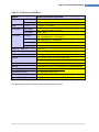
1
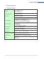
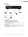
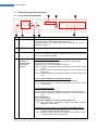
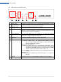
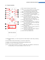
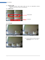
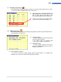
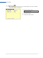
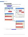
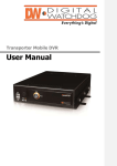
Standalone 4CH DVR User’s Manual V.1.2 Standalone 4CH DVR User’s Manual Contents 1. 1.1. Product introduction ............................................................................................................. 4 System specification .......................................................................................................... 4 2. Product operation .................................................................................................................. 5 2.1. Various split screen............................................................................................................ 5 2.2. 1channel audio recording and playback ............................................................................. 5 2.3. USB backup ....................................................................................................................... 5 2.4. Firmware upgrade via USB memory stick .......................................................................... 5 2.5. Network client viewer with various features ........................................................................ 5 3. DVR installation .................................................................................................................... 6 3.1. Package contents .............................................................................................................. 6 3.2. Installation procedure......................................................................................................... 6 3.3. System beginning .............................................................................................................. 6 Product’s name and functions .............................................................................................. 7 4. 4.1. Front panel and the buttons ............................................................................................... 7 4.2. Rear panel connection part ................................................................................................ 9 4.3. Remote controller............................................................................................................. 10 5. Display mode ........................................................................................................................ 11 5.1. QUAD mode .................................................................................................................... 11 5.2. PIP mode ......................................................................................................................... 11 5.3. FULL screen mode .......................................................................................................... 12 5.4. AUTO rotation mode ........................................................................................................ 12 5.5. TRIPLEX mode ................................................................................................................ 12 6. DVR function explanation .................................................................................................. 13 6.1. Recording ........................................................................................................................ 13 6.2. Playing back .................................................................................................................... 13 6.3. Searching ........................................................................................................................ 14 6.4. Zooming ........................................................................................................................... 16 6.5. FREEZE .......................................................................................................................... 16 6.6. USB backup ..................................................................................................................... 17 6.7. System information .......................................................................................................... 17 1| 7. Menu ..................................................................................................................................... 18 7.1. Setup menu ..................................................................................................................... 18 7.2. System menu 7.3. Display setup menu 7.4. Record menu .......................................................................................................... 25 7.5. Network menu ......................................................................................................... 26 7.6. Alarm/motion menu 7.7. Schedule record menu 7.8. USB backup menu 7.9. PAN/TILT setup 8. .......................................................................................................... 19 ................................................................................................ 23 ................................................................................................. 27 ............................................................................................ 28 ................................................................................................... 28 ...................................................................................................... 29 Network client software ...................................................................................................... 30 8.1. WEB VIEWER and DVR VIEWER: Live screen remote monitoring ................................. 32 8.2. DVR HDD PLAYER: HDD scan playback ........................................................................ 35 8.3. DVR USB PLAYER: USB backup playback ..................................................................... 37 8.4. DVR REMOTE SEARCH: Remote search ....................................................................... 39 9. 9.1. Internet Router Setting ....................................................................................................... 42 Virtual server (port forwarding) setting ............................................................................. 42 App. A. Trouble-shooting ................................................................................................................... 43 App. B. Product specification ............................................................................................................ 44 2| 3 PRIOR TO OPERATING THE SYSTEM This manual is an explanation on low cost 4channel DVR. If you are not familiar with DVR or this is the first time to use DVR itself, please contact professional technicians for installation and operation. BE CAREFUL OF THE FOLLOWINGS ! 3| Do not install the system where vibration and/or shock can be made. It can cause trouble. Turn the system off when you do cleaning and make sure to use dry towel. Do not expose the system to water or moisture. Install the system on even place where is not sealed and maintain proper temperature. Avoid the place where temperature fluctuation - causes a break-down or an electric shock is too much. And avoid the place with much moisture. Do not get on the system or do not put heavy things on the system. When you smell something burning from the system or see smog, turn the system off and contact the supplier. Product introduction 1. Product introduction 1.1. System specification Storage Up to 750GB EIDE HDD (24 Bit, 48 Bit) HDD x 1ea (MASTER) Video compression M-JPEG(Motion JPEG) Video input 4 (NTSC/PAL) channels Recording resolution 704 x 240(288), 352 x 240(288) Recording speed 120ips@CIF – NTSC, 100ips@CIF – PAL 60ips@Half D1 – NTSC, 50ips@Half D1 – PAL (CIF: 352 x 240(288), Half D1: 704 x 240(288)) Recording mode Manual recording Event recording - Motion, alarm Remote recording through network Playback mode FF: 2X ~ 32X, REW: 2X~16X, Live display 120ips @ NTSC, 100ips @ PAL Display mode QUAD, Full screen, PIP, Automated rotation Full Triplex Recording, playing back, network or backup Motion detection 5 levels sensitivity, 16 x 12 motion grid area setting Audio Input 1 port Output 1 port 4| 4 5 User‟s Manual 2. Product operation 2.1. Various split screen It processes 4channel video input at real-time, and provides various split screen (QUAD, FULL, PIP, AUTO, FREEZE). 2.2. 1channel audio recording and playback It records 1channel audio input together with video data and saves it on HDD, and you can playback the audio with the video data. 2.3. USB backup It supports USB thumb drive backup and up to USB 2.0. Motion picture backup is the feature to save proper parts in motion pictures. Besides, this backup data can be played back on PC where “Client viewer” is installed. 2.4. Firmware upgrade via USB memory stick If you want to upgrade the system via USB memory stick, please change the file‟s name to „update.bin‟ to save it in a USB memory stick. And put the stick in the DVR‟s USB port inside the front flip. And go to „USB SETUP MENU‟ and select „FIRMWARE UPDATE‟ and then it is automatically processed. After completing the procedure (takes 4 ~ 5 minutes), reboot the system. 2.5. Network client viewer with various features - 5| Various display mode(1channel/4 split) You can save the current screen that is being monitored at the Viewer in PC. You can convert the saved streaming data on your PC and live video data into AVI file to save. You can search the recorded date on the DVR remotely.. You can also view the images through Internet Explorer.. DVR installation 3. DVR installation 3.1. Package contents ① The DVR system ② Viewer CD ⑥ Remote controller 3.2. ④ Power adapter ⑤ Power plug ⑦ HDD screws and batteries, AAA Installation procedure 1. 2. 3. 4. 5. 6. 3.3. ③ User’s manual Open the package and check the items and take the DVR out. Connect the camera cables to the ports on the rear panel. Connect the monitor cable to the output port on the rear panel. Connect other devices such as networking, pan/tilt, audio and others. Connect the supplied DC 12V power adapter. Power is automatically supplied, and DVR system gets initialized, and it converts to monitoring mode in a few seconds. System beginning 1. 2. 3. 4. Images are displayed and the system gets initialized. During this process, graph is displayed. During initializing, DVR machine checks system, gets defaulted, and checks HDD etc. Initializing goes on for approximately 10 seconds. You can change the settings through SETUP screen if you want even during system operation and recording. 6| 6 7 User‟s Manual 4. Product‟s name and functions 4.1. Front panel and the buttons ③ ④ ⑤ ① ⑥ ② ⑦ ⑧ NO 1 Items Status LED Descriptions - POWER: DVR is on, and then it is lit. - PLAY: It is lit when the data is being read on HDD. - REC(Recording): It is lit when data is being recorded. In case of no recording, it gets off. 2 REMOTE Signal-receiving part 3 REC(Recording) At live monitoring mode, when you press REC button, each channel shows red icon and the images are getting recorded. If you press one more time, recording is stopped. 4 CH1/QUAD, CH2/AUTO, CH3/PIP/REW, CH4/TRI/FF (arrows) In case of live monitoring mode - Short push: It shows the proper channel‟s image in a full screen. - Long push (more than 3 seconds): QUAD: It shows 4 channels‟ images in a screen. AUTO: It rotates 4channels‟ images by channel to show them on a full screen. PIP: It shows a couple of small sub-screens on a main screen at the same time. TRI: It shows live images and playback images on a screen at the same time. In case of menu setting mode (arrows activated) - Short push: up, down and modification at the current menu - Long push (more than 3 seconds): continuous up and down at the current menu In case of playback mode - Short push: QUAD: It shows 4channels‟ images on one screen at the same time. TRI: It shows live images and playback images on a screen at the same time. REW: RW(Rewind) FF: FF(Fast Forward) ** When AUTO buttons is pressed, Triplex mode runs. - Long push (more than 3 seconds): It shows the proper channel‟s images on a full screen. In booting (in the first power on, in rebooting after USB updates) CH3: Press this button until you hear buzzer sound (about 3 secs), and then it boots to NTSC video format. CH4: Press this button until you hear buzzer sound (about 3 secs), and then it boots to PAL video format. 7| Product’s name and functions 5 PLAY/PAUSE, SEARCH/ENTER - Short push: It is used to play back the recorded data under monitoring and playback mode. One more time of push during playback makes the screen to pause. - Long push (more than 3 seconds): Search function under monitoring and playback mode. RECORD START-STOP search: List search of recording start and recording stop that users operated manually. EVENT search: List search of motion and alarm recording TIME search: Search function that users can input desired time to view - It works as „ENTER‟ as well under menu setting. 6 INFO/STOP, MENU/EXIT - Short push: It shows system information in use. - It is to get out of playback mode and then convert to monitoring mode. - Long push (more than 3 seconds): It is to get in main menu. - VGA resolution change (In booting (in the first power on, in rebooting after USB updates) In booting, press this button for app. 3 seconds until buzzer beeps, then resolution can be changed (1280*1024/1024*768, default 1280*1024). 7 Front flip - Inside is USB port and you can open this by using a groove at top right. 8 USB port - You can see this if you open the front flip. This is a port for USB memory stick. 8| 8 9 User‟s Manual 4.2. Rear panel connection part ① ② ③ ④ ⑤ ⑥ ⑦ No 1 Items Video input (1~4channel) Descriptions It supports 4 video inputs. Each of the input is independently available for black and white or color composite video input. 2 Monitor output It shows each channel‟s input image on monitor. 3 Audio in / out Live or recorded audio is available. For audio output, the speaker with amplifier or volume controller is required. (Line level audio in/out using RCA mono type connector is supported.) 4 VGA (optional) You can view images on PC monitor or TV with VGA function (1280*1024, 1024*768 resolution supported). 5 Ethernet It supports 10/100Mbps Ethernet of RJ-45 network port. 6 Alarm / Pan/Tilt Alarm input (1,2,3,4,GND) - It supports 4 alarm inputs. The equipment with ON/OFF switch or with TTL open collector such as door contact can be used. User can operate this manually. Alarm output (NC,COM,NO) - It supports 1 external output and 1 internal buzzer. Alarm status can be monitored by using alarm output or buzzer such as flash light and bell etc. And if alarm goes off, you can reset it by pressing „ENTER‟ on the front panel. The limit of volt is +5V. - In case of alarm output (relay output), it runs as long as buzzer sound set time. PANTILT(+,-) - It controls PAN/TILT cameras. Be careful of polarity of +, - to connect to RS-485. 7 Power It supplies power by the power adapter supplied by the manufacturer. 9| Product’s name and functions 4.3. Remote controller ⓐ REC: It starts recording and stops recording. ⓐ ⓑ ⓒ ⓑ LOCK: It is to lock the buttons on the front panel of DVR and the buttons of remote controller. ⓒ USB: It is for backup through USB memory stick. ⓓ ⓔ ⓕ ⓖ ⓗ ⓘ ⓙ ⓓ QUAD: It is to show 4 channel‟s images on one screen at the same time. ⓚ ⓛ ⓜ ⓞ ⓟ ⓝ ⓑ LOCK: It is to lock the buttons on the front panel of DVR and the buttons of remote controller. ⓔ FULL: It is used to view each channel (CH1~CH4). Whenever you press it, each channel is shown by the order of CH1->CH2->CH3->CH4. ⓕ PIP: Many small sub-screens in a main screen can be shown at the same time. ⓖ ZOOM: The current displayed screen is zoomed by 2x2. This function is used to see closely the small part of the images. ⓗ FREEZE: It shows paused screen of the currently displayed screen. ⓘ AUTO: It rotates 4 channels‟ images by channels to show them on a full screen. ⓙ TRI: It shows live images and playback images on one screen at the same time. ⓚ Arrows: It is for way of MENU move. ⓛ ENTER/PB(PLAYBACK): It is used to play back the saved images on HDD during monitoring mode. ⓜ SET: It is used for DVR‟s various setting, e.g. main menu or upper menu. ⓝ SEARCH: It is for searching function under monitoring and playback mode. ⓞ PAN/TILT: It is used to control PAN/TILT cameras. ⓟ INFO: It shows system information in use such as HDD model, size available or consumed and recording setting. This is only when PAN/TILT function is not in use. 10 | 10 11 User‟s Manual 5. Display mode This product provides various display modes, and they are independently executed regardless of any cases of screens or recording status. 5.1. QUAD mode Cameras titles Current time 5.2. PIP mode PIP mode 1 PIP mode 2 PIP mode 3 11 | Press PIP button, and then it works by the order of PIP mode 1->PIP mode 2 ->PIP mode 3. Display mode 5.3. FULL screen mode If you press the full screen button for certain channel, then it will be displayed on a full screen. 5.4. AUTO rotation mode If you press AUTO button, then the proper images are displayed fully on a screen by channels. 5.5. TRIPLEX mode Playback mode images and monitoring mode images are displayed at the same time. Playback mode images Monitoring mode images 12 | 12 13 User‟s Manual 6. DVR function explanation 6.1. Recording Recording kinds in case of event recording : Motion : Alarm It means “recording” now. : In case of event happened, event kinds are displayed next to the channel titles. Set time precisely, because time is recorded too in recording the images. Note. If you change time during running the DVR system, searching may not be done. When is recording made? 1. When you press REC button, recording begins. When you press one more time, it stops. 2. When motion recording is set on and there is motion detected, motion icon is shown on the screen. 3. When alarm is triggered. 6.2. Playing back It shows playback is in process Fast forward / Rewind It means there is no playback data any more. Camera number of PB: playback Recording and playback icons are displayed together. Recorded time shown 13 | You can view FULL/QUAD/TRIPLEX mode during playback. DVR function explanation 6.3. Searching 6.3.1. Manual recording searching The function to search manually recorded images. When you press ENTER, the following screen appears. Manually recorded list Currently selected list/List‟s total cases The total time of manual recording Recording start time (The time when users press REC button to start recording) Recording end time (The time when users press REC button to stop recording) 14 | 14 15 User‟s Manual 6.3.2. Event recording search The function to search images by preset sequence due to external reasons of motion/alarm/schedule recording etc. If you press „ENTER‟ button, you will see the screen as follows. Event recording list Currently selected list/List‟s total cases The channels of event happened Event (motion/alarm/schedule) start time 6.3.3. Kinds of event MOTION: motion event, ALARM: alarm event SCHED: schedule recording event Time / dates search It is the function to search certain data among all the data. When you press ENTER, you will see the screen as follows. The place where you can set desired time. Insert the desired time using arrows and press ENTER to search. Note. You should insert time only between START and END for proper search. 15 | It shows starting and ending points of the actually recorded data on HDD. DVR function explanation 6.4. Zooming It means the current status is „zoom‟. Zoom mode window. Move to the place for zooming by arrows and press ENTER. Then that place is zoomed in like the picture shown right. 6.5. FREEZE It means the current status is „freeze‟. Press FREEZE button one more time, then it releases. (Even though you make the screen frozen, recording is made without any trouble.) 16 | 16 17 User‟s Manual 6.6. USB backup USB backup can be made only during playback. During playback, find the target images and press USB button or long press(3 sec) Search button at DVR Font. Then DVR saves that data on USB memory stick. You can press the button one more time to quit. During this process, USB icon is shown on the screen. It means currently motion image is being saved via USB port. (It will be shown in 2 seconds after pressing it.) Note. During backup process, if you pull the USB drive out, system error can be occurred. Note. Backup will not run during network function. 6.7. System information DVR system‟s basic information is displayed to understand the generals such as hard drive‟s model, size, recording and playback point, recording/network setting, and software version etc. 17 | Menu 7. Menu It is menu to modify/save the set values of the current DVR system. You can control the set values for the system to be proper for users‟ purpose by setting displayed message on screen and recording specifications. 7.1. Setup menu If you press MENU/EXIT button under monitoring mode, you will see the screen as follows. ① ⑤ ② ⑥ ③ ⑦ ④ ⑧ ⑨ ① Menu to set DVR‟s basic setting. During recording, Time/Date set menu, HDD format menu, and Factory reset menu will not be activated. ② Menu for display related setting ③ Menu for recording related setting ④ Menu for network related setting ⑤ Menu for motion/alarm related setting ⑥ Menu for schedule recording related setting ⑦ Menu for USB related information and program update ⑧ Menu for pan/tilt related setting ⑨ It shows selected menu‟s name. 18 | 18 19 User‟s Manual 7.2. System menu You set system‟s basic set values. There is time/date setting, hard drive formatting, auto rotation setting, system initializing, buzzer setting, password setting, and language setting. When you select „SYSTEM SET‟, the following system setting menu screen appears. 7.2.1. 19 | Time/date setting On system setup, if you select „TIME/DATE SET‟ menu, sub-menu appears. You can set the proper menu by arrow keys (left/right: move, up/down: edit). DATE/TIME/DAY : It sets the current date/time. FORMAT : It selects the format of date/time display. „YYYY/MM/DD‟ „MM/DD/YYYY‟ „DD/MM/YYYY‟, three types are supported (default value: MM/DD/YYYY). DISPLAY : It sets whether you use date/time display or not under monitoring and/or playback mode (default value: ON). LOCATION : It selects the position of date/time display, „TOP‟ or „BOTTOM‟ (default value: BOTTOM) Menu 7.2.2. 7.2.3. Hard drive format If you select „HDD FORMAT‟ on system setup, sub-menu appears. It erases all the recorded data on HDD. If you insert password, it asks again before erasing (default password: 0000). If you select „YES‟, it erases all the data on HDD including manual recording / event recording list. Be careful of doing this! System defaulted If you select „FACTORY RESET‟ on system setup, a window of YES/NO appears. It makes all the DVR‟s set values defaulted like factory default values. 20 | 20 21 User‟s Manual 7.2.4. 7.2.5. 7.2.6. 21 | Auto rotation setting If you select „AUTO SEQUENCE SET‟ on system setup, sub-menu appears. It sets time for each channel‟s duration. It modifies auto rotated channels and time by using arrow keys. It can set number, 01~99 sec. (up/down: move, left/right: edit) During auto mode, the proper channel is displayed for the set time on a full screen. After the set time, it moves to next channel. (NO, 01~99 sec) Buzzer setting It modifies values with left and right buttons. (ON/OFF default: ON) It modifies values with left / right buttons. (ON/OFF default: OFF) If you set it „ON‟, the DVR system asks for password, and only administrator can control the DVR system in case of circumstances setting. Password on/off setting Menu 7.2.7. 7.2.8. Language setting It modifies values with left / right buttons. (ENGLISH/KOREAN/ITALIAN/CHINESE /JAPANESE/HUNGARIAN/YUGOSLAVIAN /RUSSIAN/POLISH/SPANISH) It modifies password values by arrow buttons, from 0000 to 9999. Default password: 0000 (Left/right: cipher move, up/down: edit) Password input setting 22 | 22 23 User‟s Manual 7.3. Display setup menu It is the menu of basic circumstances setting of monitoring screen. There are menus of name setting, each channel‟s brightness and contrast, boundary setting and background setting. Select „Display SETUP‟ at main menu. 7.3.1. 23 | Channel name setup It sets each channel‟s title of monitoring. If you select „NAME SET‟ under DISPLAY menu, the following sub-menu appears. Camera channel no Camera titles before editing Camera title under editing It decides channel title display on or off. If you press ENTER at a target channel, letter table as follows is displayed to set. You can select the letters using up/down/left/right buttons. Up to 8 letters can be displayed. After completing setting, press ENTER to finalize setting. Menu 7.3.2. 7.3.3. Brightness/contrast setting It controls the brightness/contrast of each channel‟s image of monitoring. If you select „BRIGHTNESS/CONTRAST‟ under DISPLAY menu, you will see the following sub-menu. It sets brightness/contrast channel by channel with arrow buttons. During this, the set value is applied to the screen right away, so users select the most proper value instantly. Each item has 11 levels of setting (up/down: channel and move to other item, left/right: edit) BOUNDARY / BACKGROUND setting. When images and the menu to set each channel‟s boundary in case of 4 split screen, PIP, and TRIPLEX are not input, this function sets the basic color displayed on screen. BOUNDARY : It sets the boundary color with left and right buttons. You can select white, gray, and black (default: white). BACKGROUND : It selects back ground color with left and right buttons. You can select blue and black. BOUNDARY BACKGROUND: It is displayed when there is no video signal. 24 | 24 25 User‟s Manual 7.4. Record menu It is the menu to set recording for monitoring screen. It can record the data suitably for users‟ demand by setting recording related items because DVR saves data on limited capacity of HDD. If you select „RECORD SET‟ on main menu, the following recording setting menu appears. You can choose the items and modify the values with arrow keys (up/down: move, left/right: edit). OVERWRITE (ON/OFF) : It decides HDD overwriting. If you select „YES‟, the oldest data are deleted to record the latest data. If you select „NO‟, recording stops when HDD is full of recorded data. RECORD SPEED : It selects how many frames (images) are recorded in recording. As the images are more, the recorded data is close to real-time, but it consumes more HDD capacity. Normally „5 Fld/1SEC‟ is set for about one week (based on 80GB HDD.). <HDD duration hours per setting> Based on VERY HIGH HIGH NORMAL LOW 25 | MAX IMAGE SIZE 65536 49152 32768 24576 60 FPS 5.157926 6.877235 10.31585 13.75447 30 FPS 10.31585 13.75447 20.6317 27.50894 12 FPS 25.78963 34.38617 51.57926 68.77235 80GB HDD 5 FPS 61.89511 82.52681 123.7902 165.0536 Unit: Hour RECORD QUALITY (VERY HIGH/HIGH/NORMAL/LOW) : It is an item to define recorded images‟ quality. In case of „VERY HIGH‟, image quality is the best, but it consumes HDD‟s capacity the most. Normally „HIGH‟ is set. For longer recording, „NORMAL‟ or „LOW‟ is set. RECORD SOURCE (704 * 240 / 352 * 240) : It sets recorded images‟ resolution. „Half D1‟ and „CIF‟, two kinds are supported. If you want to record by double times of „REC SPEED‟ set value, set it as „CIF‟. If you want to record as „REC SPEED‟ set, then set it as „Half D1‟. In other words, if you want to record 120(100) images per second, then set it as „CIF‟. AUDIO ENABLE : It selects audio channel for recording. This DVR records 1 channel audio. Menu 7.5. Network menu This is the menu to set network circumstances. In order to control the various functions of the system through network and manage/monitor remotely, you need to set network circumstances first. Select „NETWORK” menu under main menu, and then you can choose items and modify values with arrow keys (up/down: move, left/right: edit). COMMAND / DATA PORT : It sets DVR‟s network communication‟s ports. This DVR system uses the ports of „5000‟ and „5001‟. DHCP SET : This DVR system supports DHCP and DDNS. In case of static IP, it needs to be set „DISABLE‟. In case of DHCP, it needs to be set „Enable‟. In case of static IP, contact network manager to set the circumstances. In case of DHCHP/DDNS, all the values are set automatically. Besides, in case of DHCP set, it also supports DDNS for remote access so that you can always access the system automatically even though the IP address is changed. How to check & change MAC Address Under „NETWORK SETUP‟ menu, press REC button 4 times in a row, and then MAC address of the DVR system will be shown. 26 | 26 27 User‟s Manual 7.6. Alarm/motion menu It is the menu to set sensor input, alarm output, and motion setting. This DVR system supports 4 channels of sensor input and 1 channel of alarm output (relay output). Besides, each of 4 channels can be set independently for motion recording. Select „SENSOR SETUP‟ at main menu and you can choose items and modify values (up/down: move, left/right: edit). CHANNEL SELECT : It selects a channel. ALARM ENABLE : It sets alarm input type (NO, NC, OFF). MOTION ENABLE (ON/OFF) : It sets motion detection. MOTION LEVEL.(VERY LOW/LOW/NORMAL/HIGH/VERY HIGH) : It sets motion detection‟s sensitivity. If you set it VERY HIGH, motion recording will be made even though there is very little motion. COMPARE FRAMES (00~15) : This sets how many images are used for motion detection. Normally 2 frames are set. EVENT RECORD TIME (OFF, 01~99 MIN, CONTINUE) : This is the function to record images in motion detection. It records images as set. BUZZER SOUND (NO USE, 01~99 SEC) : In case of motion detected, alarming sound goes off. It sets buzzer sound duration time. If you set „NO USE‟, the sound does not go off at all. AREA SET : As motion detection area set, the following screen appears. The part filled with yellow color is the area where motion is going to be detected. 27 | Menu 7.7. Schedule record menu This DVR system supports schedule recording. It can select certain desired time to record for one week. Select „SCHEDULE SETUP‟ at main menu. Select days with up and down buttons and press ENTER to set. Set start and end time with up, down, left and right buttons. After done, press ENTER to move to other days. Finally, if you want to use schedule record, you should set „SCHEDULE ENABLE‟ on. 7.8. USB backup menu You can save the playback file for backup and update the system through USB thumb drive. Select „BACKUP‟ at main menu. USB TOTAL SIZE : It shows USB memory‟s total capacity that is stuck to the DVR system. If the system does not recognize USB memory stick, it displays „NO DETECT‟. REMAINING SIZE : It shows available capacity. If the system does not recognize USB memory stick, it displays „NO DETECT‟. USB FIRMWARE UPDATE : It is used to update the DVR‟s system with the latest firmware. It is updated with Update.bin file. The system reboots automatically after update. 28 | 28 29 User‟s Manual 7.9. PAN/TILT setup This is the menu to set PAN/TILT camera. This DVR supports one channel of PAN/TILT control. Select „PAN/TILT‟ at main menu. 29 | PAN/TILT cameras‟ protocol Note. Recommendation : PELCO-D, PELCO-P. Set ID at the camera Set baud rate value at camera Network client software 8. Network client software This DVR‟s client program consists of four kinds of software by function. You can view the images through web browser. Web viewer: Input http://www.dvr-cctv.net at the address bar. Select “STANDALONE 4CH DVR” at top. Note. When you can‟t see web viewer screen, please refer to the next page about Active X errors. Copy the contents provided in the CD on PC‟s HDD space or execute the CD‟s contents directly. DvrViewer.exe: It is used to monitor the current images. DvrHddPlayer.exe: It is used to view the HDD recorded at DVR after connecting the HDD to your computer. DvrUSBPlayer.exe: It is used to view USB backup data on PC. DvrRemoteSearch.exe: It is used to search the recorded data on the DVR‟s‟ HDD at client PC. 30 | 30 31 User‟s Manual <IN CASE OF ACTIVEX ERRORS > 1. - [Tools]->[Internet options]->[Security]->[Trusted sites]-> Click Sites. - Add http://www.dvr-cctv.net - Add http://222.236.47.42 - Not select require server verification (https:) for all sites in this zone 2. 31 | Registration at Truseted sites. After setting above, access http://www.dvr-cctv.net and click “STANDALONE 4CH”. Network client software 8.1. WEB VIEWER and DVR VIEWER: Live screen remote monitoring ① ② ④ ③ ① ⑧ ⑦ ⑥ ⑤ It shows images‟ channel title. ② It shows each channel‟s monitoring mode images. If you double click certain channel, that channel will be shown in a full screen. One more double click makes it into 4 split screens. ③ It shows the current time and operation status message. ④ Pan/tilt control button: This function controls pan/tilt cameras remotely (up, down, left, right). ⑤ Program termination button 32 | 32 33 User‟s Manual AVI file saving button: It saves the currently displayed screen at Viewer in AVI ⑥ format. Instant saving is directed to ‘Local rec path’ of ⑦. You can redirect the path by clicking ⑦ icon. Option button - In case of network disconnected This is the button to set IP, video source, and saving path etc. If you click it, you will see the window as follows. 33 | In case of static IP, input the IP directly. In case of DDNS, please see below. Input ports which are set at DVR network setting. (default values 5000, 5001 used) It sets the path to save M-JPEG stream or AVI file. In case of dynamic IP (ADSL, VDSL etc), click DDNS setting icon. When MAC address input-window appears, input MAC address that is shown on DVR rear side, and click „Try to connect‟. And then you will see the process of finding IP at DDNS. When it‟s done, you can see the DVR‟s dynamic IP address. Network client software - In case of network connected You can control remotely the setting menus such as DVR‟s recording, motion/sensor, schedule recording, PTZ setting. Note. After setting modification, if you press OK button, the local DVR system gets rebooted and modified to the new setting values. ⑧ Access button The target DVR which is set at ⑦ above is shown, and input password that is set at the DVR to try access. (default password: 0000) 34 | 34 35 User‟s Manual 8.2. DVR HDD PLAYER: HDD scan playback HDD scan function is to play back the HDD‟s recorded data on the DVR after you connect the HDD to PC directly. ① ② ⑥ ① ⑤ ④ ③ It shows images‟ channels‟ title. ② It shows each channel‟s playback mode‟s images. If you double click certain channel, that channel can be shown on a full screen. One more double click makes it 4 split screen. ③ 35 | Program termination button Network client software ④ AVI file saving button: It saves the currently displayed screen at Viewer in AVI format. Instant saving is directed to „Local rec path‟ of ⑦. You can redirect the path by clicking icon. ⑤ HDD selection window ⑥ PLAYER: Play Pause Progress bar of data playback Move to the front/ end Audio ON/OFF Move of frame by frame During playback and pause 36 | 36 37 User‟s Manual 8.3. DVR USB PLAYER: USB backup playback USB backup playback is a function to play back the backup data saved on USB memory stick on PC. Connect the recorded USB pen drive to PC and play back the recorded data. ① ② ⑥ ⑤ ① ④ ③ It shows images‟ channel title. ② It shows each channel‟s playback mode‟s images. If you double click certain channel, that channel can be shown on a full screen. One more double click makes it 4 split screen. ③ 37 | Program termination button Network client software ④ 38 Button for file open: It opens image data of backup data. ⑤ Go to the path of the saved backup data and click the desired data to playback. Note. It can only play back the type of MJPEG stream (*.dvr) data. AVI file saving button: It saves the currently displayed screen at Viewer in AVI format. Instant saving is directed to „Local rec path‟ of ⑦. You can redirect the path by clicking icon. ⑥ PLAYER: Play Pause Progress bar of data playback Move to the front/ end Move of frame by frame During playback and pause 38 | 39 User‟s Manual 8.4. DVR REMOTE SEARCH: Remote search ① ② ③ ① ② ③ ④ 39 | ⑨ ⑦ ⑥ ⑧ ⑤ ④ It shows images‟ channel title. It shows each channel‟s monitoring mode images. If you double click certain channel, that channel will be shown in a full screen. One more double click makes it into 4 split screens. It shows the current time and operation status message. Program termination button Network client software ⑤ AVI file saving button: It saves the currently displayed screen at Viewer in AVI format. Instant saving is directed to „Local rec path‟ of ⑦. You can redirect the path by clicking ⑥ icon. Environment setting button This is the button to set IP, video source, and saving path etc. If you click it, you will see the window as follows. Network setting In case of static IP, input the IP directly. In case of DDNS, please see below. Input ports which are set at DVR network setting. (default values 5000, 5001 used) It sets the path to save M-JPEG stream or AVI file. In case of dynamic IP (ADSL, VDSL etc), click DDNS setting icon. When MAC address input-window appears, input MAC address that is shown on DVR rear side, and click „Try to connect‟. And then you will see the process of finding IP at DDNS. When it‟s done, you can see the DVR‟s dynamic IP address. 40 | 40 41 User‟s Manual ⑦ Access button The target DVR which is set at ⑦ above is shown, and input password that is set at the DVR to try access. (default password: 0000) Note. Concurrent access with Network Viewer is not supported. ⑧ Search button: This is used to bring the list of manual and event(motion, alarm, schedule) recording from the DVR. Note. Data search can be done with the network connected (process ③ “connected to xxx.xxx.xxx.xxx” message check) If you select the wanted list to play back, you will see the list shown on the left picture. Double-click one of the data on the list, then the proper data is played.. <Manual recording list> <Event recording list> ⑨ Playback control button: These buttons are to control the selected data‟s playback speed. REW PLAY PAUSE재생 FF Note. You can‟t use RemoteSearch‟s playback at the same time as the local DVR‟s playback. 41 | Internet Router Setting 9. Internet Router Setting 9.1. Virtual server (port forwarding) setting How to set is various from model to model. This guide is for ipTIME G104 of EFM networks. You need to set the DVR‟s port #5000~5001. 42 | 42 43 User‟s Manual App. A. Trouble-shooting 43 | Troubles Power does not get on. Check-points Please check the external SMPS status. Can‟t see live display images. Please check camera cable connection. Please check monitor cable connection. Please check camera power status. Live images are too bright. Please check camera input status. Please check camera‟s brightness setting. DVR stops recording. Please check “overwrite” recording mode in the SETUP menu. The initial booting takes more than 20 seconds. Please check if HDD jumper connection is “MASTER”. Please check HDD information on INFO screen is “NO DETECT”. In booting, HDD: NO DETECT message is shown.. Please check if the HDD is installed in the DVR.. Please check if HDD connection cable is done properly. Please try another HDD. During DVR working, it reboots automatically. Under Search mode, please go in REC START/STOP SEARCH. Then please check if “REBOOT HDD ERROR” is at END TIME. The above message means the currently used HDD has bad sector, so you need to replace it with another HDD if it often happens. App. B. Product specification App. B. Product specification Models Video 4 channel standalone type DVR Input 4 composite (BNC) Output 1 Composite (BNC), 1 VGA optional Audio In / out 1 in (RCA) / 1 out (RCA) Live display Video signal NTSC - Real time display @ 704x480 PAL - Real time display @ 704x576 Compression Motion JPEG Recording Resolution Speed NTSC: 704x240(Half D1), 352x240(CIF) PAL: 704x288(Half D1), 352x288(CIF) NTSC: 60fps@Half D1, 120fps@CIF PAL: 50fps@Half D1, 100fps@CIF Mode Motion, Sensor, Manual, Schedule Image quality Very high, High, Normal, Low Sensor in / alarm out 4 in / 1 out System control IR Remote controller / Key buttons / Network PTZ control RS-485, pan / tilt Storage 1ea of internal HDD. Up to EIDE 750GB HDD Backup USB thumb drive, HDD reading at PC, AVI convert Search Time / Event list / Manual recording list Network 10/100Mbps ethernet, RJ-45, DDNS/DHCP, Dedicated software Power supply DC 12V/3.5A/external SMPS based on 1ea of HDD Dimensions & weight 30 x 6(height) x 22cm, 4 kgs Operating temperature 5℃ ~ 40℃ Operating humidity 0% ~ 90% This specification may be changed for better quality without prior notice. 44 | 44 45 User‟s Manual Memo 45 | 46 Memo 46 |