1
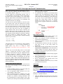
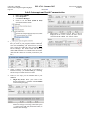
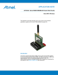
University of Florida
Electrical & Computer Engineering Dept.
Page 1/4
EEL 4744 – Summer 2015
Dr. Eric M. Schwartz
30-Jun-15
Revision 2
Lab 5: Interrupts and Serial Communication
OBJECTIVES
• Explore and understand microprocessor interrupts. In
part A of this lab, you will use XMEGA external
interrupt system.
• Learn how to utilize asynchronous serial
communication. In part C of this lab, you will use
XMEGA’s USART system to transmit/receive
characters to/from computer terminal as well as write
interrupt driven USART routines and explore
multitasking.
5.
REQUIRED MATERIALS
• uPAD and Proto Base kit and tools
• DAD (Diligent Analog Discovery) kit
• No new hardware
• XMEGA documents
• doc8331, section 12, 13, and 23
• doc8385, section 33 (pinout and pin functions)
YOU WILL NOT BE ALLOWED INTO YOUR LAB
SECTION WITHOUT THE REQUIRED PRE-LAB.
6.
PRELAB REQUIREMENTS
REMEMBER:
You must adhere to the Lab Rules and Policies document
for every lab.
PART A: EXTERNAL INTERRUPTS
In Lab 2 of this course, you added switches to your board.
You had to continuously poll the input port to know the
state of the switches. Polling wastes processor clock
cycles and results in a slow response time if the processor
is engaged in another instruction execution task. What if
you wanted the processor to respond instantly to any
changes on an input switch? The answer is to utilize
external interrupts.
1.
2.
3.
4.
Read doc8331, sections 13.5-13.7 regarding external
interrupts on the XMEGA chip. Then read section
13.13, which discusses the various registers you will
need to use.
Read doc 8331, chapter 12 about the Programmable
Multilevel Interrupt Controller (PMIC). Pay close
attention to section 12.5 regarding interrupt levels.
Connect a single switch to any unused pin of your
choice (PORTs E or F). Be sure that your keypad
circuit remains functional for future labs.
You will initialize XMEGA to trigger an interrupt
when a rising edge is detected on the input. The
interrupt service routine (ISR) should only execute
when the pin value changes from to GND to VCC to
GND. However, because we are unable to debounce
the switches on our board, the ISR will fire on both
edges. Therefore, inside the ISR you will have to test
the value of the pin and only complete the desired
function if the pin is the correct level.
7.
8.
Your initializations should proceed as follows:
a. Select an interrupt priority level in the interrupt
control register (PORTx_INTCTRL) for a port
of your choosing.
b. Select a pin on that same port as a source for
the interrupt in one of the interrupt mask
registers (PORTx_INTnMASK).
c. Be sure to select the data direction for the input
pin. Do not make assumptions.
d. Select the input/sense configuration for the pin
you selected in the PORTx_PINnCTRL
register. Make sure you select sense rising
falling edge.
e. Turn on appropriate PMIC interrupt level in the
(PMIC_CTRL) control register.
f. In any interrupt driven application, the global
interrupt flag should be the last thing you set
during initializations. Simply use the sei
instruction to set the global interrupt flag to
enable the interrupt.
The processor needs to know what code to execute
when an interrupt occurs. After an interrupt occurs,
there is a specific address to which the processor will
jump. This address is called the interrupt vector
address. The name of the vector for this interrupt is
PORTx_INTn_vect where x and n are defined by
you, based on the interrupt pin that you selected.
This vector’s value is defined in the “Our
ATxmega128A1U Register Descriptions” file (the
included file) available from the Software/Docs
section of the class website. (In C, the vector’s
values are available in the avr/io.h file.)
Write an ISR to display a count of how many times
interrupt has been executed, on your LEDs. (Be sure
to initialize the count to zero and LED pin directions
to output) The label of the ISR must be the same as
the name of the vector that represents it
(PORTF_INT0_vect, for example), and end with a
reti instruction. The label of the ISR must be the
same as what you used in the interrupt rjmp or jmp
instruction after the org to the interrupt vector. The
ISR must end with a reti instruction. The reti
instruction is a special return statement reserved only
for interrupt service routines and is (slightly)
different from a ret instruction. By naming your
ISR the same as the vector, the compiler knows how
to put the appropriate rjmp/jmp instruction in the
vector table, based on where it locates the actual
routine in memory. With this jump instruction, the
processor knows what to execute when your external
interrupt occurs.
You must, as always, put the origin of your program
at 0x200 or beyond. This is necessary because the
interrupt vectors, which we will use from this lab
onward, are located in the lower 506 addresses of
program memory (0x000-0x1FA). You would also
University of Florida
Electrical & Computer Engineering Dept.
Page 2/4
EEL 4744 – Summer 2015
Dr. Eric M. Schwartz
30-Jun-15
Revision 2
Lab 5: Interrupts and Serial Communication
still need an appropriate jmp or rjmp instruction at
.org 0x0. The 0x0 address is the reset interrupt
vector, which cause your program to start executing
at the address corresponding to the label for this jmp
or rjmp instruction.
9. Make sure your interrupt routine is working correctly
by putting a breakpoint inside of it. (Remember the
interrupt will seem to fire on both edges because of
bouncing.)
10. Real switches bounce, so the count will probably be
wrong! Record the number of bounces that you see
when the switch goes from low to high and from high
to low. (Do this a few times to see if it is always the
same.). Put the shortest possible delay routine inside
your ISR. The delay should be near the start of the
ISR, in order to give the pin time to stop bouncing
before you read its value. Set your breakpoint after
you check the pin’s level to make sure you are
executing the counting only on a rising falling edge.
11. Use your DAD’s oscilloscope to record the bouncing
(used in part 10). Submit a screenshot in your lab
document.
PART B: ASYNCHRONUOUS SERIAL
COMMUNICATION
Asynchronous serial communication can be done entirely
in software by “bit banging.” For example, if you
understand the format of asynchronous serial data (see
class notes and Figure 23-5 in the doc8331), and you want
to send data, then all you have to do to transmit a block of
data on a GPIO pin. You would output the following bits
at the required frequency or baud rate: start bit, 8 data bits
(least significant bit first), and then a stop bit. This bit
banging is NOT part of the lab requirements but is always
an option if the processor has no support for serial
communication. Similarly, a receiver can be made by
sampling inputs at the appropriate times.
PART C: XMEGA USART System
The XMEGA has several universal synchronous
asynchronous receiver transmitter (USART) peripherals.
One of them, PORTD’s USARTD0, is connected to the
USB port labeled J3 on the uPAD through a FTDI USB
bridge chip (FT232RL). See the uPAD schematic and
user manual for more information. Determine which pins
on PORTD are used for USARTD0 using table 33-3 in
doc8385 (alternate pin functions). (You won’t need this
info, but include this answer in your prelab.)
In this part of the lab you will write a program to send and
receive data between uPAD and your laptop using
USARTD0.
You will need to install a terminal program on your laptop
to communicate with your board. Some examples are
Bray Terminal (also known as Br@y++ Terminal),
PuTTY, X-CTU, RealTerm, and HyperTerminal. Install
and familiarize yourself with one of them. (A description
on how to use Bray Terminal is given in the Appendix.)
The example program used in class is available on our
web site (SCI_Polling.asm) and can be used as a starting
point for your program.
To successfully complete this portion of the lab, I suggest
that you create the subroutines/functions described below.
1.
2.
3.
4.
USART Initialization function (USART_INIT). This
function will take care of all of USART
initializations.
a. Set the data direction of the PORTD USART bits
to the corresponding values for Tx and Rx.
b. For your uPAD, PORTQ bits 1 and 3 control the
source of the serial signals from the XMEGA.
Initialize these pins as outputs and output the
appropriate values to these to pins.
c. Set the baud rate to 14,400 Hz (bits per second)
by storing the appropriate value in the baud rate
registers. (You can use a program at
http://tinyurl.com/lhunuy2 to verify your baud
rate calculation, but be sure that you know how
to calculate these for your lab quiz and exams.)
d. Set the USART for asynchronous mode, 8 data
bits, no parity, 1 start bit, and 1 stop bit.
Character output subroutine (OUT_CHAR). This
subroutine will output a single character to the
transmit pin of the XMEGA’s USART system.
a. Check if the previously transmitted character has
been completed; if not, keep checking until it has
been completed.
b. Transmit the character passed to the subroutine.
String output subroutine (OUT_STRING). This
routine will output character strings stored in
memory.
a. Read the character pointed to by Z and increment
the pointer.
b. If this character is not null, call OUT_CHAR,
and repeat for each non-null character that
follows; otherwise return from the subroutine.
Character input subroutine (IN_CHAR). This
subroutine will receive a single character from the
receiver pin of the XMEGA’s USART system.
a. Check if a character has been received, if not,
keep checking until it has been received.
b. Read the character from the receive buffer
Write an interactive program to display your favorite
activities on any terminal of your choice. The menu you
will create should look like this:
your_name’s favorite:
1.
Movie
2.
Book
3.
Food
4.
Ice cream/yogurt flavor
5.
Pizza toppings
6.
Redisplay menu
ESC: exit
7.
University of Florida
Electrical & Computer Engineering Dept.
Page 3/4
EEL 4744 – Summer 2015
Dr. Eric M. Schwartz
30-Jun-15
Revision 2
Lab 5: Interrupts and Serial Communication
When your program first starts it should display the above
menu using OUT_STRING subroutine and then wait for
an incoming character. When a 1, 2, 3, 4, 5 or 6 is
received, output the corresponding message, such as
“Cookie Monster’s favorite food is cookies” and redisplay
the menu. If the received character is an escape (ESC)
character, output “Done!” and terminate execution. If any
other character is received, ignore it. For readability, add
a blank line between every message.
You will need two special characters to cause the curser
to move down a line. These two characters are carriage
return (CR) and line feed (LF). The carriage return will
move the cursor all the way to the left and line feed will
move the cursor to the next line. These characters should
occur in order at the end of every line. In addition, an
escape character (ESC) will be used to terminate your
program (Note: On at least one tablet PC last year, the
ESC key code did NOT return a $1B. If this is the case for
your computer, just pick another key and let Dr. Schwartz
and your TA know by sending them emails. Also
document this in your pre-lab report.) Add the following
equates to your .asm file
.equ CR = 0x0D
.equ LF = 0x0A
.equ ESC = 0x1B
ASCII characters can be represented as a single character
in single quotes (e.g., ‘A’) or a string of characters in
double quotes (“e.g., this is a string of ASCII
characters”). CR and LF can be represented as ‘\r’ and
‘\n’.
The best way to write and debug code is to test as you
write it. I suggest that you start by writing a simple
program to read a character (using IN_CHAR), then write
a simple program to output a character (using
OUT_CHAR), and then write program to echo what is
received with IN_CHAR by transmitting the read data
using OUT_CHAR. Write a final simple program to test
your OUT_STRING subroutine before finally writing the
required program to display the menu and execute the
menu specified tasks.
PART D: Interrupt Driven Receiving
We have already used interrupts in part A of this lab. Now
you will use your knowledge to create an interrupt driven
echo program.
1.
2.
3.
Initialize USART as in part C, except also enable low
level receiver interrupt (using CTRLA).
Turn on appropriate PMIC interrupt level in the
control (PMIC_CTRL) register.
Write an ISR (triggered on a USART receive) that
echoes the received data to the transmitter. Writing
an ISR is very similar to writing a subroutine, with
the main differences of often needing to clear a flag
(caused by the interrupt) and returning with an RETI
4.
instead of a RET. You will also generally need to
push and pop several registers.
To demonstrate the concept of an interrupt driven
program, after your initializations, toggle an LED
“forever” with a 0.37 second delay in a loop in the
main routine, and do nothing else! At the same time,
if you type a key on your terminal, your program
should echo it back inside an ISR. The interrupt
should now do all the work for you. A properly
interrupt driven program should have the following
format:
PRE-LAB QUESTIONS
1. List the XMEGA’s USART registers used in your
programs and briefly describe their functions.
2. What is the difference between synchronous and
asynchronous communication?
3. What is the difference between serial and parallel
communication?
4. List the number of bounces from part A of this lab.
How long (in ms) is your delay routine for
debouncing?
5. What is the maximum possible baud you can use for
asynchronous communication if your board runs at
2 MHz? Support your answer with the values you
would place in any special registers that are needed.
IN-LAB REQUIREMENTS
1. Part A: Demonstrate your external interrupt program
executing on your board.
2. Part C: Demonstrate your USART menu program
executing on your board.
3. Part D: Demonstrate your interrupt driven echo
program executing on your board.
4. Answer any questions your TA may ask you about
your hardware and software.
APPENDIX
Using Bray Terminal
You will first need to download the Bray program from
our website at http://mil.ufl.edu/4744/software/Bray.exe.
More information about this program is available at the
website https://sites.google.com/site/terminalbpp/.
After you write your program, you will need to configure
the Br@y++ terminal as follows:
1.
With your XMEGA Board powered you will need to
determine the virtual serial port that was created. To
do this:
University of Florida
Electrical & Computer Engineering Dept.
Page 4/4
EEL 4744 – Summer 2015
Dr. Eric M. Schwartz
30-Jun-15
Revision 2
Lab 5: Interrupts and Serial Communication
a.
b.
c.
d.
Right click Computer
Select Properties
Click Device Manager
Check to see the Ports (COM & LPT)
associated with the UART:
5.
2.
Open up Br@y++ terminal and match the settings
that you wrote in your program, and the COM Port.
Note: Set handshaking (not shown below) to none.
Note: Select the COM port that you found in the
Device Manager. The Atmel board will show up
under USB Serial Port. It is COM4 in this screenshot.
(Note that the values are not what you need for your
lab.)
3.
Select “Connect” on the top left. If everything is
installed correctly, you should NOT get a warning,
and be ready to transmit and receive data.
4.
There are two ways you can transmit data to your
XMEGA:
a. Single Key Press: Place your cursor at the
bottom of the Br@y++ terminal in the Transmit
section and begin typing:
b.
Send Queued Data: Place your cursor in the
white box and type a message; when done press
“-> Send’ on the right side (not shown below) to
send the entire message:
When Br@y++ terminal receives data, it will be
displayed in the receive section, the data can be
viewed in ASCII or HEX. We will use ASCII.