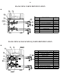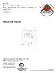
1
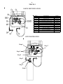
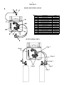
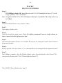
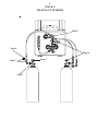
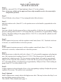
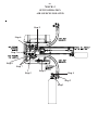
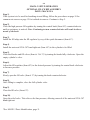
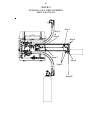
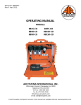
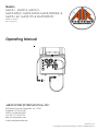
Models
MACK-1, MACK-2, MACK-3,
MACK-NFPA1, MACK-NFPA3, MACK-NFPA3Q, &
MACK-1-6K, MACK-3TV & MACKNFPATV
Manual No. POA051
(Rev 4 April 2011)
Operating Manual
AIR SYSTEMS INTERNATIONAL, INC.
829 Juniper Crescent, Chesapeake, Va. , 23320
Telephone (757) 424-3967
Toll Free 1-800-866-8100
Fax No. (757) 424-5348
http://www.airsystems.com
e-mail: [email protected]
Printed in U.S.A
©Copyright Air Systems International, Inc. 2009. All Rights Reserved.
-2-
TABLE OF CONTENTS
Overview...........................................................................................................................................3
MACK-1 Setup, Operation & Parts Identification...................................................................4-5
MACK-2 Setup, Operation & Parts Identification...................................................................6-7
MACK-2 Filling Cylinders...........................................................................................................8-9
MACK-3 Setup & Operation for Common Air Sources, Parts Identification...................10-11
MACK-3 Setup & Operation for Isolated Air Sources.........................................................12-13
MACK-3 Setup & Operation for Optional Fill Whip Assembly MACK-3FA...................14-15
MACK-NFPA1 & MACK-NFPA3 Parts Identification.............................................................16
MACK-NFPA1 & MACK-NFPA3 Setup & Operation..............................................................17
Changing Cylinders.......................................................................................................................18
Shutdown Procedure......................................................................................................................18
High Pressure Airline General Maintenance & Inspection.......................................................18
Warranty Disclaimer......................................................................................................................19
-3-
OVERVIEW
The MACK series has been designed as a portable multifunctional air distribution system. All
MACK units are rated for 5000psi.
MACK-1
This version allows for one or two high pressure cylinders to be attached to the supply inlet
whips. A CGA-347 male inlet is provided for direct attachment to a bank of air cylinders. All
MACK series units have at least one air outlet manifold with pressure adjustments from 0-125psi.
MACK-2
This version has the same features as the MACK-1, with the addition of an adjustable fill regulator, pressure gauge, and fill whip. An optional second fill whip is available.
MACK-3
The MACK-3 contains two independent low pressure manifolds and regulator systems that each
have their own cylinder supply hoses. An isolation valve is located between the regulators to
isolate the systems, as well as provide common air flow from a single bottled air source. One
regulator is set to provide low pressure air (0-125psi) for respirators, and one for medium pressure air (0-250psi) for air shores and other rescue tools. This medium pressure manifold has an
additional low pressure regulator/manifold system for additional respirators and tools. A total of
eleven outlets are provided. The MACK-3FA version contains all of the above items, with the
addition of a complete bottle fill assembly, model number MACK-FA.
MACK-NFPA1
This version contains two in dependent MACK-1 manifold and regulator systems, so that each
one has its own cylinder supply hoses and low pressure whistle. A total of 6 low pressure outlets
are provided.
MACK-NFPA3
This version of the MACK-NFPA1 contains two independent low pressure manifold and regulator systems, so that each has its own cylinder supply hoses. An isolation valve is added between
the systems to isolate the regulators, as well as provide common air flow from a single bottled air
source. A CGA-347 high pressure inlet is provided on this version to allow for an external bank
of air cylinders to operate the unit.
-4-
MACK-1 SETUP/OPERATION
Step 1)
Install the universal CGA-347 hand tight nuts (Item #7) to the cylinder valves and tighten.
Step 2)
Close all bleeder valves (Item #8) by turning the knobs fully clockwise.
Step 3)
Open one cylinder. At this time the low pressure warning alarm will sound until it sets itself at
approximately 1000psi (69bar). Check reading on gauge (Item #1) to verify that cylinder is full.
Close the cylinder.
Step 4)
Set the required respirator pressure with the regulator control knob (Item #10). Turn clockwise to
increase pressure, counterclockwise to decrease pressure.
Step 5)
Bleed the pressure at either the relief valve (Item #9), or by partially engaging a male plug into
one of the respirator couplings (Item # 11/12). This depressurizes the manifold and simulates low
cylinder pressure. The low pressure warning alarm (Item #6) will sound at approximately 500psi
(35bar). Open the other cylinder. At this time the low pressure warning alarm (Item #6) will resound until it sets itself at approximately 1000psi (69 bar). Check reading on gauge (Item #1) to
verify cylinder is full.
Step 6)
Couple respirators and lengths of hoses to the manifold and readjust pressure regulator (Item #10)
if necessary. The system is now operational.
Step 7)
Optional
Install a high pressure connect whip to the high pressure inlet. This step may be done after Step 5,
or at anytime during operation of the system.
-5-
MACK-1
PARTS IDENTIFICATION
ITEM #
1
2
3
4
5
6
7
8
9
10
11
11A
12
12A
13
DESCRIPTION
INCOMING PRESSURE GAUGE (0-200PSI)
LIGHT ASSEMBLY
PRESSURE CAP
CGA-347 MALE ADAPTER
¼" MALE/MALE CHECK VALVE
LOW PRESSURE WHISTLE
CGA-347 HAND TIGHT NUT/NIPPLE
BLEED VALVE
RELIEF VALVE
REGULATOR
RESPIRATOR FITTING--HANSEN
DUST CAP--HANSEN
RESPIRATOR FITTING--SCHRADER
DUST CAP--SCHRADER
OUTGOING PRESSURE GAUGE (0-6000PSI)
SETUP/OPERATION
Step 6
Step 5
Step 4
Step 3
Step 2
Step 1
Step 7
PART #
GA256KS
MACKLIGHT
SS347CAP
SS4F347AM
VC4MMSS
AC-PA25
SS347HT
VAL030
VR4150BR
REG-5000
QDH3SL6M
QDH3DCAP
QDSSL6M
QDSDCAP
GA25200S
-6-
MACK-2 SETUP/OPERATION
Step 1)
Install the universal CGA-347 hand tight nuts (Item #3) to the cylinder valves and tighten.
Step 2)
Close all bleeder valves (Item #2) by turning the knobs fully clockwise.
Step 3)
Open one cylinder. At this time the low pressure warning alarm (Item #7) will sound until it sets
itself at approximately 1000psi (69bar). Check reading on gauge to verify that cylinder is full.
Close the cylinder.
Step 4)
Set the required respirator pressure with the regulator control knob (Item #11). Turn clockwise to
increase pressure, counterclockwise to decrease pressure.
Step 5)
Bleed the pressure at either the relief valve (Item #9), or by partially engaging a male plug into
one of the respirator couplings (Item 13/14). This depressurizes the manifold and simulates low
cylinder pressure. The low pressure warning alarm (Item #7) will sound at approximately 500psi
(35bar).Open the other cylinder. At this time the low pressure warning alarm (Item #7) will resound until it sets itself at approximately 1000psi (69 bar). Check reading on gauge (Item #8) to
verify cylinder is full.
Step 6)
Couple respirators and lengths of hoses to the manifold and readjust pressure regulator if necessary. The system is now operational.
Step 7)
Optional
Install a high pressure connect whip to the high pressure inlet. This step may be done after Step 5,
or at anytime during operation of the system.
-7-
MACK-2
PARTS IDENTIFICATION
ITEM #
1
2
3
4
5
6
7
8
9
10
11
12
13
13A
14
14A
15
16
DESCRIPTION
ON/OFF VALVE
BLEEDER VALVE
CGA-347 HAND TIGHT NUT AND STEM
FILL REGULATOR
CGA-347 MALE ADAPTER
PRESSURE CAP
LOW PRESSURE WHISTLE
INLET PRESSURE GAUGE (0-6000PSI)
RELIEF VALVE (150PSI)
CHECK VALVE
PRESSURE REGULATOR
OUTLET PRESSURE GAUGE (0-200PSI)
QUICK DISCONNECT, HANSEN
QUICK DISCONNECT, SCHRADER
DUST CAP, HANSEN
DUST CAP, SCHRADER
FILL PRESSURE GAUGE (0-6000PSI)
LIGHT ASSEMBLY
PART #
VAL020
VAL030
SS347HT
REG001
SS4F347AM
SS347CAP
AC-PA25
GA256KS
VR4150BR
VC4MMSS
REG-5000
GA25200S
QDH3SL6M
QDSSL6M
QDH3DCAP
QDSDCAP
GA256KS
MACKLIGHT
SETUP/OPERATION
Step 7
Step 6
Step 4
Step 3
Step 5
Step 2
Step 1
-8-
MACK-2
FILLING CYLINDERS
Step 1)
2216/4500psi cylinder fill: Install the universal CGA-347 handtight nut (Item #3*) to the
empty cylinder’s valve, and tighten.
Note: An optional CGA-347 to CGA-346 adapter/relief valve is available. The relief valve is set
to 2400psi.
Step 2)
Close the fill and bleeder valves (Item #s 1&2*).
Step 3)
Open empty cylinder valve.
Step 4)
Open the cascade/air supply source. Note: It is highly recommended you use a high volume air
source connected to the high pressure inlet.
Step 5)
Adjust the fill regulator (Item # 4*) to desired fill pressure by turning the control knob clockwise
to increase pressure.
Step 6)
Slowly open the fill valve (Item # 1*) to a desired fill rate by turning the knob counterclockwise.
Step 7)
Once filling is complete, close the fill and cylinder valves. Open the bleeder valve (Item #2*)to
vent pressure. Remove the CGA-347 hand tight nut (Item #3*).
*See MACK-2 Parts Identification, page 7.
-9-
MACK-2
FILLING CYLINDERS
Step 5
Step 6
Step 4
Step 3
Step 2
Step 1
-10-
MACK-3 SETUP/OPERATION
COMMON AIR SOURCES
Step 1)
Install the universal CGA-347 hand tight nuts (Item #4) to the cylinders.
Step 2)
Close all bleeder valves (Item # 3) by turning the knobs fully clockwise.
Step 3)
Index the isolation valve (Item #21) so the position arrow on the handle is inline with the plumbing.
Step 4)
Open one cylinder. At this time, the low pressure warning alarms (Item #7) will sound until they
set themselves at approximately 1000psi (69 bar). Check the reading on the gauge (Item #19) to
verify that the cylinder is full. Close the cylinder.
Step 5)
Set the required tool pressure with the regulator control knob (Item # 18). Turn clockwise to
increase, counter clockwise to decrease pressure.
Step 6)
Set the required respirator pressure(s) with the regulator control knob (Item # 15). Turn clockwise to increase, counterclockwise to decrease pressure.
Step 7)
Bleed the pressure at either the relief valve (Item # 11), or by partially engaging a male plug into
one of the respirator/tool couplings (Item #12/12A). This depressurizes the manifold and simulates low cylinder pressure. The low pressure warning alarms (Item #7)will sound at approximately 500psi (35 bar).Open the other cylinder(s). At this time the low pressure warning alarms
(Item #7) will sound until they reset themselves at approximately 1000 psi (69 bar). Check reading on gauge (Item #19)to verify cylinder is full.
Step 8)
Couple respirators/tools and length of hoses to the corresponding couplings. Readjust the pressure
regulators if necessary. The system is now operational.
Step 9) Optional
Install a high pressure connect whip to the high pressure inlet. This step may be done after step 7,
or at any time during operation of the system.
-11-
MACK-3
PARTS IDENTIFICATION
ITEM #
1
2
3
4
5
6
7
8
9
10
11
12
12A
13
13A
14
15
16
17
18
19
20
21
22
23
24
25
26
DESCRIPTION
HIGH PRESSURE QUICK DISCONNECT
ON/OFF VALVE
BLEEDER VALVE
CGA-347 HAND TIGHT NUT/STEM
CGA-347 MALE ADAPTER
PRESSURE CAP
LOW PRESSURE WHISTLE
FILL REGULATOR
FILL WHIP CONNECTION
FILL PRESSURE GAUGE
RELIEF VALVE (150PSI)
QUICK DISCONNECT, HANSEN
QUICK DISCONNECT, SCHRADER
DUST CAP, HANSEN
DUST CAP, SCHRADER
OUTLET PRESSURE GAUGE (0-160PSI)
PRESSURE REGULATOR
CHECK VALVE
RELIEF VALVE (275PSI)
AIR SHORE REGULATOR
INLET PRESSURE GAUGE (0-6000PSI)
OUTLET PRESSURE GAUGE (0-1000PSI)
SYSTEM ISOLATION VALVE
PRESSURE REGULATOR
OUTLET PRESSURE GAUGE (0-200PSI)
LIGHT ASSEMBLY
INLET PRESSURE GAUGE (0-6000PSI)
QUICK DISCONNECT, HANSEN
Step 9
Step 8
Optional Fill Assembly
Part # MACK-3FA
Step 3
Lower Whip
Assemblies
Step 7
Step 4
Step 6
Step 5
MACK-3 SETUP/OPERATON
COMMON AIR SOURCES
Step 2
Step 1
PART #
QDHKSL4FSS
VAL020
VAL030
SS347HT
SS4F347AM
SS347CAP
AC-PA25
REG001
QDHKPL4FSS
GA256KS
VR4150BR
QDH3SL6M
QDSSL6M
QDH3DCAP
QDSDCAP
GA20160S
WL014
VC4MMSS
VR4275BR
REG007
GA206KS
GA201KS
VAL073
REG-5000
GA25200S
MACKLIGHT
GA256KS
QDH3SL4M
-12-
MACK-3 SETUP/OPERATION
AIR SOURCES ISOLATED
Step 1)
Install the universal CGA-347 hand tight nuts (Item # 4*) to the cylinders.
Note: At least one cylinder on the upper and lower whip assemblies needs to be connected for
independent operation.
Step 2)
Close all bleeder valves (Item # 3*) by turning the knobs fully clockwise.
Step 3)
Index the isolation valve (Item #21*) so the position arrow on the handle is perpendicular to the
plumbing.
Step 4)
Open one cylinder from the upper and lower whip assemblies. At this time the corresponding low
pressure warning alarms (Item #7*) will soung until they set themselves at approximately 1000psi
(69 bar). Check the reading on the gauges (Item #s 19 & 25*) to verify that the cylinders are full.
Close the cylinders.
Step 5)
Set the required tool pressure with the regulator control knob (Item # 18*). Turn knob clockwise
to increase, or counterclockwise to decrease pressure.
Step 6)
Set the required respirator pressure(s) with the regulator control knob (Item # 15*). Turn
clockswise to increase, counterclockwise to decrease pressure.
Step 7)
Bleed the pressure at either the relief valve (Item # 11*) or by partially engaging a male plug into
one of the respirator/tool couplings (Item #s 12/12A*). This despressurizes the manifold, and
simulates low cylinder pressure. The low pressure warning alarms will sound at approximately
500psi (35 bar). Open the other cylinder(s). At this time the low pressure warning alarms (Item
#7*) will sound until they reset themselves at approximately 1000psi (69 bar). Check reading on
gauge (Item #19*) to verify cylinder is full.
Step 8)
Couple respirators/tools and lengths of hose to the corresponding couplings. Readjust the pressure
regulators if necessary. The system is now operational.
Step 9) Optional
Install a high pressure connect whip to the high pressure inlet. This may be done after Step 8, or at
any time during operation of the system.
*See MACK-3 Parts Identification, page 11.
-13-
MACK-3
SETUP/OPERATION
AIR SOURCES ISOLATED
Step 9
Step 6
Step 3
Step 8
Step 7
Step 5
Step 8
Step 4
Step 2
Step 1
-14-
MACK-3 SETUP/OPERATION
OPTIONAL FILL WHIP ASSEMBLY
PART # MACK-3FA
Step 1)
If the system is to be used for breathing air and filling, follow the procedures on page 10 for
common air sources or page 12 for isolated air sources. Continue to Step 2.
Step 2)
Close the high pressure fill regulator by turning the control knob (Item #8*) counterclockwise
until no resistance is noticed. Note: Continuing to turn counterclockwise will result in the removal of the knob.
Step 3)
Install the fill whip onto the fill regulator by way of the quick disconnect (Item #1*).
Step 4)
Install the universal CGA-347 hand tight nut (Item #4*) to the cylinder to be filled.
Step 5)
Close the bleeder and fill valves (Item #s 2 & 3*) by turning the knobs fully clockwise. Open the
empty cylinder’s valve.
Step 6)
Adjust the fill regulator (Item #8*) to the desired pressure by turning the control knob clockwise
to increase pressure.
Step 7)
Slowly open the fill valve (Item # 2*) by turning the knob counterclockwise.
Step 8)
Once filling is complete, close the full cylinder valve.
Step 9)
Close the fill valve (Item #2*).
Step 10)
Open the relief valve. This relieves the line pressure, allowing removal of the universal CGA-347
hand tight nut.
*See MACK-3 Parts Identification, page 11.
-15-
MACK-3
OPTIONAL FILL WHIP ASSEMBLY
PART # MACK-3FA
Step 7
Step 2
&
Step 6
Step 5
Step 3
Step 4
Step 9
Step 10
-16-
MACK-NFPA1 PARTS IDENTIFICATION
ITEM #
DESCRIPTION
PART #
1
2
2A
3
3A
4
5
6
7
8
9
10
RELIEF VA LVE, 125 PSI
QUICK-CONNECT, HA NSEN
QUICK-CONNECT, SCHRA DER
DUST CA P, HA NSEN
DUST CA P, SCHRA DER
OUTLET PRESSURE GA UGE
PRESSURE REGULA TOR
LOW PRESSURE W HISTLE
INLET PRESSURE GA UGE
CHECK VA LVE
BLEEDER VA LVE
CGA -347 HA ND-TIGHT
VR4125BR
QDH3SL4M
QDSSL4M
QDH3DCA P
QDSDCA P
GA 20160B
REG-5000NG
A C-PA 25
GA 2075KB
VC4M M SS
VA L030
SS347HT
MACK-NFPA3 & MACK-NFPA3Q PARTS IDENTIFICATION
ITEM #
DESCRIPTION
PART #
1
RESPIRATOR COUPLING, HANSEN QDH3SL4M
1A RESPIRATOR COUPLING, SCHRADER QDSSL4M
2
DUST CAP, HANSEN
QDH3DCAP
2A
DUST CAP, SCHRADER
QDSDCAP
3
RELIEF VALVE
VR4125BR
4
OUTLET GAUGE, 0-160 PSI
GA20160B
5
PRESSURE REGULATOR
REG-5000NG
6
LOW PRESSURE W HISTLE
AC-PA25
7
INLET GAUGE,
GA2075KB
8
SUPPLY ISOLATION VALVE
VAL073
9
CHECK VALVE
VC4MMSS
10
BLEED VALVE
VAL030
11
CGA-346/CGA-347 HAND-TIGHT
SS347HT
12
CGA-347 MALE ADAPTER
SS4F347AM
13
PRESSURE CAP
SS347CAP
14
QUICK FILL PLUG - OPTIONAL
ST878MFST
-17-
MACK-1-6K PARTS IDENTIFICATION
ITEM #
1
2
3
4
5
6
7
8
9
10
10A
11
11A
12
DESCRIPTION
PART #
LOW PRESSURE W HISTLE
AC-PA25
CHECK VALVE
VC4SMMSS
HIGH PRESSURE INLET FITTING, 6000 PSI MAX QDHKPL4FSS
BLEED VALVE
VAL030
CGA-347 HAND-TIGHT NUT/NIPPLE
SS347HT
PRESSURE GAUGE
GA2075KB
PRESSURE REGULATOR
REG009
OUTLET PRESSURE GAUGE
GA20160B
RELIEF VALVE
VR4150BR
RESPIRATOR FITTING, HANSEN
QDH3SL4M
RESPIRATOR FITTING, SCHRADER
QDSSL4M
DUST CAP, HANSEN
QDH3DCAP
DUST CAP, SCHRADER
QDSDCAP
LIGHT ASSEMBLY (NOT SHOW N)
MACKLIGHT
-18-
MACK-NFPA1& MACK-NFPA3(Q)
SETUP & OPERATION
Note: Low pressure (2216psi) and high pressure (4500psi) cylinders can be used.
Step 1)
Install CGA-347 connections to cylinder valves and tighten with hand tight wheels.
Step 2)
Make sure all bleeder valves are turned fully clockwise to prevent air loss, and open one cylinder.
At this time the low pressure alarm whistle will sound. It will continue until the pressure reaches
approximately 1000psi (69 bar).
Low Pressure Alarm Test
Set the required respirator pressure with the regulator control knob, and bleed the pressure at
either the relief valve, or by partially engaging a male plug into one of the respirator couplings.
This depressurizes the manifold and simulates low cylinder pressure. The low pressure warning
alarm will sound at approximately 500psi (35 bar). Open the other cylinder. Check reading on
gauge to verify cylinder is full.
Step 3)
Couple respirators and lengths of hoses to the manifold and readjust pressure regulator if necessary. The system is now operational.
Step 4) Optional for MACK-NFPA3
The CGA-347 inlet can be used as an alternate incoming air source. Set the selector valve to the
common, vertical position, or isolated, horizontal position.
STEP 2
STEP 3
STEP 1
STEP 4
-19-
CHANGING CYLINDERS
To change a cylinder while the unit is still in use:
1. Open the second cylinder and note the gauge pressure.
2. Close the drained cylinder.
3. Open the bleeder valve to relieve line pressure. Remove the CGA-347 hand tight nut.
4. Remove the drained cylinder and install a full cylinder in its place. Reinstall the CGAconnections. Close bleeder valves. The cylinder is now ready for use when the other
cylinder’s pressure descends to 500psi.
Note: The system is equipped with check valves that will prevent backflow from the other
cylinder in use.
SHUTDOWN PROCEDURE
1. Cylinder valves must be shut and line pressure relieved through the relief valve.
2. Remove CGA-347 connections from cylinders and reinstall valve covers for storage
and transportation.
HIGH PRESSURE AIRLINE GENERAL MAINTENANCE & INSPECTION
Monthly
1. Check regulatos, gauges, and valves for external leakage.
2. Inspect cylinder valves for proper closure.
3. Check cylinder pigtails for cleanliness, flexibility, wear, leakage, blisters on hose, and
thread damage. Replace damaged pigtails immediately.
4. Inspect check valves for closure ability.
Annually
1. Check relief valve’s pressure setting.
2. Check regulator function by opening and closing regulator valve knob fully.
Every 4 years
1. Replace all flexible pigtails.
-20-
MACK-3TV
PARTS IDENTIFICATION
ITEM #
1
2
3
4
5
6
6A
7
7A
8
9
10
11
12
13
14
15
15A
16
17
18
19
20
DESCRIPTION
LOW PRESSURE WHISTLE
AUXILIARY INLET
PRESSURE CAP
AUXILIARY INLET LOW PRESSURE BELL
0-160 PSI PRESSURE GAUGE
HANSEN COUPLING, 3/8" MPT
SCHRADER COUPLING, 3/8 MPT
HANSEN DUST CAP
SCHRADER DUST CAP
125 PSI RELIEF VALVE
PRESSURE REGULATOR
CHECK VALVE
BLEEDER VALVE
CGA-347 HAND-TIGHT
350 PSI RELIEF VALVE
PRESSURE REGULATOR WITH GAUGES
HANSEN COUPLING, 1/4" MPT
SCHRADER COUPLING, 1/4" MPT
ISOLATION VALVE
PRESSURE REGULATOR
0-200 PSI PRESSURE GAUGE
LIGHT ASSEMBLY
0-6000 PSI PRESSURE GAUGE
PART #
AC-PA25
SS4F347AM
SS347CAP
AC-PA25B
GA20160S
QDH3SL6M
QDSSL6M
QDH3DCAP
QDSDCAP
VR4125BR
WL014
VC4SMMSS
VAL030
SS347HT
VR4350BR
REG015
QDH3SL4M
QDSSL4M
VAL073
REG-5000NG
GA25200SRG
MACKLIGHT
GA256KSREG
-21-
MACKNFPATV
PARTS IDENTIFICATION
ITEM #
1
1A
2
2A
3
4
5
6
7
8
9
10
11
12
13
14
DESCRIPTION
PART #
RESPIRATOR COUPLING, HANSEN
QDH3SL4M
RESPIRATOR COUPLING, SCHRADER
QDSSL4M
DUST CAP, HANSEN
QDH3DCAP
DUST CAP, SCHRADER
QDSDCAP
RELIEF VALVE
VR4125BR
OUTLET GAUGE, 0-160 PSI
GA20160B
PRESSURE REGULATOR
REG-5000NG
LOW PRESSURE WHISTLE
AC-PA25
INLET GAUGE, 0-6000 PSI
GA206KB
SUPPLY ISOLATION VALVE
VAL073
CHECK VALVE
VC4MMSS
BLEED VALVE
VAL030
CGA-346/CGA-347 HAND-TIGHT
SS347HT
CGA-347 MALE ADAPTER
SS4F347AM
PRESSURE CAP
SS347CAP
AUXILIARY INLET LOW PRESSURE BELL
AC-PA25B
-22-
Warranty Disclaimer
Air Systems’ manufactured equipment is warranted to the original user against defects in workmanship or materials under normal use for one year after date of purchase. Any part which is determined by Air Systems to be defective in material or workmanship will be, as the exclusive remedy,
repaired or replaced at Air Systems’ option. This warranty does not apply to electrical systems or
electronic components. Electrical parts are warranted, to the original user, for 90 days from the
date of sale. During the warranty period, electrical components will be repaired or replaced at Air
Systems’ option.
NO OTHER WARRANTY, EXPRESSED OR IMPLIED, AS TO DESCRIPTION, QUALITY, MERCHANTABILITY, FITNESS FOR A PARTICULAR PURPOSE, OR ANY
OTHER MATTER IS GIVEN BY AIR SYSTEMS IN CONNECTION HEREWITH. UNDER NO CIRCUMSTANCES SHALL THE SELLER BE LIABLE FOR LOSS OF
PROFITS, ANY OTHER DIRECT OR INDIRECT COSTS, EXPENSES, LOSSES OR
DAMAGES ARISING OUT OF DEFECTS IN, OR FAILURE OF THE PRODUCT OR
ANY PART THEREOF.
The purchaser shall be solely responsible for compliance with all applicable Federal, State and
Local OSHA and/or MSHA requirements. Although Air Systems International believes that its
products, if operated and maintained as shipped from the factory and in accordance with our “operations manual”, conform to OSHA and/or MSHA requirements, there are no implied or expressed
warranties of such compliance extending beyond the limited warranty described herein. Product
designs and specifications are subject to change without notice. Rev 2 12/98
Air leaks are not covered under warranty except when they result from a defective system
component, i.e. an on/off valve or regulator or upon initial delivery due to poor workmanship. Air leaks due to poor delivery or damage will be covered under delivery claims. Minor
air leaks are part of routine service and maintenance and are the responsibility of the customer just as are filters and oil changes.