1
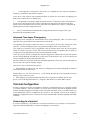
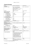
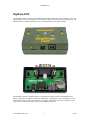
DigiSnap 2700 DigiSnap 2700 The DigiSnap 2700 is a variation of the DigiSnap 2000, adding a Real-Time Clock, simplified for use with modern digital cameras, and includes a set of connections optimized for long term time-lapse projects. The DigiSnap 2700 was tailored specifically for use in the Harbortronics Time-Lapse Package. The DigiSnap 2700 has a simplified feature set compared to the other members of the DigiSnap 2000 family, reducing the configuration complexity substantially. The DigiSnap 2700 is intended for use with SLR and other 'contact' style camera interfaces. In addition, a Real-Time Clock has been added, to more easily use the Advanced Time-Lapse feature of the DigiSnap controllers. www.Harbortronics.com 1 8/9/10 DigiSnap 2700 This DigiSnap has no internal battery, but is powered via a connector to a 5V power source, such as an AC adapter, or the Harbortronics Battery Converter. New to the DigiSnap controller series is the ability to control power to the camera, lighting, or strobe via connection to the Harbortronics Battery Converter. Block diagram The following block diagram shows a typical application of the DigiSnap 2700. The DigiSnap controls the power to the camera, as well as the shutter release. Standard Operation : Status Indicator The LED on the top of the case indicates how the DigiSnap is working. It may flash green, red or yellow/orange. During operation, the DigiSnap will flash green periodically to signal that it is working properly, and to indicate in which state it is operating. Checking this interval is an easy way to determine the operating state. Time between Flashes Operational State 4 sec Simple Time-Lapse 6 sec Terminal Connection 8 sec Advanced Time-Lapse 12 sec Single Snap www.Harbortronics.com 2 8/9/10 DigiSnap 2700 Waking the DigiSnap The DigiSnap 2700 will automatically wake when power is applied. If the DigiSnap is shut off, for instance at the end of a Simple Time-Lapse sequence, you can re-awaken it by pressing any button, or activating the input trigger signal. When awakened and connected to a camera, the indicator will flash amber/yellow briefly. Following that initial amber flash, there will be a green or red sustained flash, indicating whether the internal Real-Time Clock is set. If the clock is not set, the color will be Red, and you may wish to reconfigure the clock for proper ATL operation. A few seconds later, the DigiSnap 2700 should flash 4 times Green in quick succession, indicating that it is ready to control a camera. When connected to a terminal, the initial amber flash will be followed by a single Green, to indicate that it's attached and communicating with a terminal. Taking a single picture A single picture may be taken at any time by momentarily pressing the * button. The images captured are retained in the camera, exactly as if the camera were used without a remote control. After each picture has been taken, the DigiSnap will briefly flash green, to indicate success. Note that the DigiSnap 2000 series controller does not alter camera setting. Therefore you should be able to set the camera up manually for most any situation, and the DigiSnap will continue to use those settings. Time-Lapse Photography Time-lapse operation can be used to automatically take a number of pictures with a period of time between each shot. The DigiSnap can use either of two different Time-Lapse techniques, called ‘Simple TimeLapse’ (STL), and ‘Advanced Time-Lapse’ (ATL). Any and every critical application should be tested before it is actually used in the field to verify reliability. The DigiSnap controllers are consumer products, and Harbortronics cannot and does not guarantee operation for any critical application. During Time-Lapse operation, the DigiSnap buttons are still active. If there is a need to take an additional picture in between those of the time-lapse sequence, simply press the button, and the DigiSnap will command the camera to take a picture immediately, without interrupting the time-lapse sequence. Simple Time-Lapse A Simple Time-Lapse (STL) sequence consists a number of pictures taken with a particular interval between each picture. The number of pictures to capture in the sequence can be set from 1 to 65535, or infinite by entering 0. Many applications require the camera to continue to take pictures until turned off later. The infinite setting is useful for these applications. The time-lapse interval may be set from 0 seconds, to 255 hrs, 59 minutes, and 59 seconds, which is over 10 days. There are three ways to initiate the STL sequence. www.Harbortronics.com 3 8/9/10 DigiSnap 2700 1 If the DigiSnap is configured for STL mode (see configuration), then when the DigiSnap is awakened, it immediately starts the STL sequence. At the end of a STL sequence (the programmed number of pictures have been taken), the DigiSnap will flash yellow to indicate that it is shutting down. 2. If the DigiSnap is operating in Single Snap mode, then the button (time-lapse control function) may be used to start and stop an STL sequence. This button can also program the interval in the field (please refer to Switch Menu section for more detail). Note that when the STL sequence is completed, the DigiSnap will revert back to Single Snap mode. 3. There is switch function available that does nothing but start the STL sequence. This is also described in the Switch Menu section. Advanced Time-Lapse Photography The DigiSnap can be configured for Advanced Time-Lapse (ATL) photography, where a set of Time-Lapse sequences can be programmed to start at particular times of the day. The DigiSnap 2700 includes a Real-Time Clock, so you can specify the exact daily starting time of the sequences. Note that the DigiSnap clock may possibly drift slightly relative to the camera clock. Up to eight sets of sequences may be programmed to start at particular times of the day. Each sequence consists of a number of pictures to take, and an interval between them. The DigiSnap does not check for overlaps between the programmed intervals, so please plan them carefully. As the ATL process consists of multiple STL sequences triggered per a daily clock, the observant operator may note that the DigiSnap will flash green at either the 8 second period for ATL, or the 4 second period for STL, depending on the operating state at that time. The ATL operation is intended for multi-day unattended applications, and as such will run until either the power is lost, or the sequence manually stopped. There are two ways to initiate the ATL process. 1 If the DigiSnap is configured for ATL mode (see configuration), then when the DigiSnap is awakened, it immediately starts the ATL process. Note that there is no ‘end’ to an ATL process… it will continue day after day. In our integrated Time-Lapse Package, it may continue for years! 2 If the DigiSnap is operating in Single Snap mode, then it is possible to manually start the ATL process, if one of the DigiSnap buttons is re—mapped to that function (see Switch Menu section). Terminal Configuration In order to configure the settings, the DigiSnap is designed to communicate directly to a computer terminal (or terminal emulator). Once the terminal is set up, the cable connected between the DigiSnap and the terminal, waking the DigiSnap will display a menu of available commands. There is a wealth of features, so several independent menus of configurations are presented. The DigiSnap 2700 has been designed to simplify the configuration choices, so there are less menus available than in the other DigiSnap 2000 family controllers. Connecting to a terminal If you have a desktop PC, you probably have a serial port on the back of your computer. Use the supplied beige cable (labeled Null-Modem), to connect the DigiSnap to your serial port. www.Harbortronics.com 4 8/9/10 DigiSnap 2700 If you have a newer laptop or a Mac, you may need to buy a USB to Serial converter, and install it's drivers. These are available at any computer store from $15 and up. You now need to run a program to open up a terminal window. If you are running Linux, you already know how to do this! If you have a windows PC you can use the DigiSnap_Terminal.exe program supplied on the CD Rom. If you are using a Mac, you can download a shareware program called ZTerm, or you may already have a terminal program installed with your particular OS. The particular COM settings needed are listed in the DigiSnap 2000 manual. Once you have your terminal program running, and ‘connected’, cycle the power on the DigiSnap (flip the toggle switch off and on again), and you should see it present a menu on the screen. You can select the different menus or particular commands. Once you have configured the DigiSnap via a terminal, the settings are saved forever, or until the next time you change them using this same procedure. If you have problems getting the 'terminal' working with the DigiSnap, please refer to the “Terminal Instructions” article on the CD-Rom. If you suspect any problem with our equipment, please call us! Example menus for version 4.01 of the firmware are duplicated below, with descriptions of each command. Depending on the model and selected camera interface of your DigiSnap, not all of these menus or menu items will be available. ***** www.Harbortronics.com ***** DigiSnap Clock : 10:25:00 2000/07/29 DigiSnap 2700 Firmware : July 31, 2010, Version 4.01 Main Menu Operating Mode : Advanced Time-Lapse Camera Release Time : 002 Sec Power to Camera : Always On Power On Polarity : 001 Simple Time-Lapse Settings # of Shots : 00010 Interval (HHH:MM:SS) : 000:00:05 Commands (enter a single letter) M - Set Operating Mode I - Change the Camera Interface www.Harbortronics.com 5 8/9/10 DigiSnap 2700 P – Configure Power to Camera T - Configure the Simple Time-Lapse settings A - Advanced Time-Lapse Configuration Menu W - Switch Menu C – Set the Clock Q - Quit (Save Changes, Shut off) Note that the menu header displays the internet address of Harbortronics, the internal clock time and date, as well as the model number, firmware version and build date. To enter a command, the letter is entered (upper or lower case) followed by the <Enter> key. If the <Enter> is entered without a command, the menu will be refreshed. • M – Set Operating Mode This command will ask which mode to use when the DigiSnap initially wakes up. S - Single Picture T - Simple Time-Lapse A - Advanced Time-Lapse DigiSnap Application (S,T,A)? (S) Single Snap : Does nothing until a button is pressed. This is useful as a remote shutter release, or to test the Time-Lapse Package. (T) Simple Time-Lapse : Starts a STL sequence immediately upon wakeup. (A) Advanced Time-Lapse : Starts the ATL process immediately upon wakeup. • I - Change the Camera Interface The DigiSnap 2000 family of controllers were developed to accommodate the variety of shutter release / control interfaces that the many manufacturers provided on their cameras. The DigiSnap 2700 has been tailored somewhat to simplify the configuration, and to work specifically with the Harbortronics TimeLapse Package. Most SLR cameras use a simple 'contact' style interface, so the DigiSnap 2700 was developed with only this style interface. Selecting this command will allow configuration of the camera release Hold time, which is simply the period of time that the DigiSnap 2700 will effectively 'press' the shutter release on the camera. Most SLRs www.Harbortronics.com 6 8/9/10 DigiSnap 2700 are fast enough to wake up and take a picture in 1 to 2 seconds. If your camera is set for auto focus, it may need a longer time. The default Hold time is 2 seconds. • P – Configure Power to Camera The DigiSnap 2700 has an output signal which may be used to control the power to a camera or lighting, synchronously with the shutter release. For instance, while taking pictures of plants, you may wish to control artificial lighting so that it comes on moments before taking the picture, and then shutting it off afterwards, to not affect the plant growth. In some situations, you may need a high powered photoflash to illuminate the scene, such as underwater. Keeping the strobe powered at all times may draw more power then needed, or even reduce the life of the strobe. Some cameras may not shut down to a minimum power state between pictures, and require removal of power between pictures. Some of the Canon Rebel series, exhibit a rare, but debilitating lock-up, where the camera will not respond to any buttons, the power switch etc., and can only be cleared by opening the memory card door or removing power to the camera. Again this is a rare event, but when performing a long term time-lapse, this is totally unacceptable! One of the primary features of the DigiSnap 2700 was to address this particular camera bug. The DigiSnap 2700 can be configured to control the power to a camera, or external lighting device. There are several ways you may wish to control the power, depending on the application, and the device being controlled. When entering the P command, a list of alternatives are presented. 1: Always On 2: Always Off 3: Toggle Off Daily 4: Toggle Off After Snap 5: On Before, Off After Snap – 5 Sec 6: On Before, Off After Snap – 10 Sec 7: On Before, Off After Snap – 20 Sec 8: On Before, Off After Snap – 40 Sec Power Control Mode: ? When set to Always On, or Always Off, the power is left on or off respectively at all times. When powering a camera that manages it's own power properly, leaving the power on is a good choice. Leavingt the power off might be useful when testing a strobe system for instance. When set to Toggle Off Daily, the DigiSnap will leave the power on at all times, except after the first picture taken after midnight. After that picture is taken, the DigiSnap will leave the power on for 10 more seconds, then remove the power for 3 seconds, and turn it back on again. This should be enough to clear a lock-up in a camera, without affecting cameras that are working properly. This is probably an optimum setting to use when using a Canon Rebel camera that is exhibiting an occasional lock-up. When set to Toggle After Snap, the DigiSnap will leave the power on at all times, except for a few seconds, after each picture. After each picture is taken, the DigiSnap will leave the power on for 10 more seconds, then remove the power for 3 seconds, and turn it back on again. www.Harbortronics.com 7 8/9/10 DigiSnap 2700 When set to On Before, Off After Snap, the DigiSnap will leave the power off at all times, except when actually taking the picture. The DigiSnap turns power on, then a number of seconds later takes the picture. The power is left on for a number of seconds later, then turned off until the next picture is taken. These modes are useful for conserving battery power on cameras that do not shut down to a minimum power state between pictures, and most useful for controlling lighting, charging photoflashes, etc. Output Polarity (typ 1) (0..1): ? This configuration is provided to allow use with different devices that actually provide the power switching. Note that the DigiSnap 2700 does not include a power switch, it merely provides a signal which can be used to control a relay, or other electronics. When using the DigiSnap 2700 with the Harbortronics Battery Converter, which may be the most frequent device used with the DigiSnap, the proper setting would be a polarity of 1, which is noted in the configuration question. Please consult with Harbortronics when using other power control devices, for the proper configuration. • T – Simple Time-Lapse settings In the DigiSnap 2700, A Simple Time-Lapse sequence is defined by the number of pictures to take, and the interval between them. This command will ask for these numbers. How many pictures to take? (0..65535) [0=Infinite] ? The number of pictures may be set to any number between 0 and 65535. If set to 0, then this indicates to the DigiSnap to take an infinite number of pictures. Effectively this means that the DigiSnap will request pictures as long as power is maintained in the camera and DigiSnap. How many Hours between pictures (0..255)? How many Minutes between pictures (0..59)? How many Seconds between pictures (0..59)? The maximum interval between pictures is 255 hours, 59 minutes, 59 seconds. The minimum delay can be set to 0 hours, 0 minutes, and 0 seconds, which will essentially tell the DigiSnap 2000 to command new pictures be taken as soon as possible after the previous picture. This minimum interval is going to be determined by the Camera Interface setting (shutter release hold time), and the Power Control mode selected. • A – Advanced Time-Lapse settings This command leads to the Advanced Time-Lapse Menu (following section) • W – Switch settings www.Harbortronics.com 8 8/9/10 DigiSnap 2700 This command leads to the Switch Menu (following section) • C – Set the Clock Unlike the other members of the DigiSnap 2000 family, the DigiSnap 2700 includes a real-time clock, so that it know what time of day it is at all times. When the DigiSnap 2000 model was released, it was intended for use with the Nikon Coolpix type cameras, as well as a few other models that could exchange commands and time via a serial connection. When using a the simple contact style interface, the DigiSnap can no longer read the time of day. The Real Time Clock in the DigiSnap 2700 over comes this, allowing better use of the Advanced Time-Lapse mode. This command allows setting the date and time stored within the DigiSnap 2700. This time is maintained with a battery that should last many years. Harbortronics will be happy to replace a battery that no longer keeps the time and date for a small fee. Note that the time is set and displayed in a 24 hr format.... for instance, 3 PM is 15 hrs. • Q – Quit This command is used to disconnect the DigiSnap controller, saving the changes made during the session. If the Q command is not entered, the DigiSnap 2700 will automatically save any changes and shut off after 90 seconds, if no activity is detected. Pressing any of the buttons on the DigiSnap will also shut the DigiSnap off when connected to the terminal. Advanced Time-Lapse Menu The DigiSnap can be configured to take a series of Time-Lapse sequences at specific periods of the day. ATL Period # 1 Enabled 00002 Shots, Starting 21:05 Interval 00:00:15 ATL Period # 2 Disabled 00005 Shots, Starting 06:00 Interval 00:00:15 ATL Period # 3 Disabled 00005 Shots, Starting 07:00 Interval 00:00:20 ATL Period # 4 Disabled 00005 Shots, Starting 09:00 Interval 00:00:10 ATL Period # 5 Disabled 00005 Shots, Starting 10:00 Interval 00:00:20 ATL Period # 6 Disabled 00005 Shots, Starting 11:00 Interval 00:00:20 ATL Period # 7 Disabled 00005 Shots, Starting 12:00 Interval 00:00:20 ATL Period # 8 Disabled 00005 Shots, Starting 13:00 Interval 00:00:20 www.Harbortronics.com 9 8/9/10 DigiSnap 2700 Commands (enter a single letter) 1..8 : Configure Period 1..8 Q - Quit (Return to Main Menu) • 1..8 Select a sequence to configure. Each sequence is independently defined, and can be configured without concern for their particular position in the list. There is no error checking performed on the sequences, so it is possible to define sequences which overlap each other, and overlap the 24 hr period, creating undefined behavior. Each sequence may be enabled or disabled. If disabled, its settings are effectively ignored. The number of pictures may be set from 1 to 65535. The starting time (per the camera’s internal clock) may be set to any minute of the day or night, using a 24 hr format. For example, 19:25 would be 7:25 PM. The interval may be set from 0 seconds to 12 hrs, 59 min, 59 sec. • Q – Quit This command returns control to the Main menu. Switch Menu Switch 1 Function : G Switch DigiSnap Off Switch 2 Function : E Time-Lapse Control Switch 3 Function : B Take Picture Immediately Switch 4 Function : G Switch DigiSnap Off External Switch Function : B Take Picture Immediately Commands (enter a single letter) 1 - Configure Switch 1 (Far Left) 2 - Configure Switch 2 (Center Left) 3 - Configure Switch 3 (Center Right) 4 - Configure Switch 4 (Far Right) 5 - Configure External Switch Q - Quit (Return to Main Menu) www.Harbortronics.com 10 8/9/10 DigiSnap 2700 The DigiSnap 2000 series controllers are unique in that the user may configure the switch functions. The user may configure the action for each switch independently, allowing for selection of the features most appropriate to the task at hand. The default mapping is perhaps the most appropriate for normal remote shutter release operations using SLR cameras. Note that the DigiSnap 2700 controller has the capability to be triggered from an external electrical signal, which could range from a simple switch to a light beam detector. Contact Harbortronics if you have a particular custom application in mind! We have already worked with a number of photographers and commercial companies to develop special purpose equipment. • 1..5 – Configure Switch function There are a number of switch functions defined for the DigiSnap 2000 series controllers, not all of which are useful for the DigiSnap 2700. A Do Nothing B Take Picture Immediately C Zoom Out D Zoom In E Time-Lapse Control F G Switch DigiSnap Off H I J K Start STL L Start ATL M Stop TimeLapse A. Do Nothing Pressing the button will not do anything. B. Snap – Take a picture Pressing the button will cause a picture to be taken immediately, even during a Simple or Advanced TimeLapse operation. C. Not supported in the DigiSnap 2700. D. Not supported in the DigiSnap 2700. www.Harbortronics.com 11 8/9/10 DigiSnap 2700 E. Time-Lapse Control When pressed very briefly (i.e. less than one second), the Simple Time-Lapse sequence will be alternately started and stopped. When pressed and held for an extended time, the Simple Time-Lapse interval can be programmed in the field! After being held for about two seconds, the DigiSnap will flash yellow each second, allowing the user to count off the desired time interval before releasing the button. The number of pictures is automatically set to infinite, and the initial delay set to zero. Once programmed, the Time-Lapse operation may be started by pressing the button again briefly. Pressing the button briefly when the time-lapse in progress will halt the time-lapse operation. For example… Let’s say you are using the DigiSnap as a simple shutter release to take some studio portraits, and decide that you would like to pose with your model. One way is to use a long extension cord on the DigiSnap, and then try to hide it behind you when you take the picture. What you could do instead is quickly set the DigiSnap to take pictures every 5 or 10 seconds. You press and hold the button (time-lapse control function), and after a couple seconds it starts to flash yellow. Keep holding it until you count off say 8 flashes (8 seconds), and release it. Press it again briefly, and it will start taking pictures at the every 8 seconds! Walk over and pose, and away you go… after a few shots you lose track of the camera timing, and you begin to look more natural in the resulting pictures. When you are finished, simply press the button again briefly, and the DigiSnap returns to operating as a simple shutter release. Perhaps you are on safari at your local park or zoo, and you see some wild animal staking it’s prey, you notice that a skywriter is spelling out a message, that the clouds are doodling wonderfully, your child is happily climbing a tree, or the fireworks show is about to begin. Shooting movie sequences is not really appropriate for the slower action, and you’d rather sit back and watch than baby-sit the camera. Within seconds you’ve configured the DigiSnap, and it’s taking a sequence of pictures for you, that you can convert to a movie when you return from safari. The field-programmed interval is not retained when the DigiSnap turns off. When the DigiSnap is turned back on, it will use the interval last configured via a terminal. F. Not supported in the DigiSnap 2700. G. Power Off When pressed, the DigiSnap will shut itself off, and will command the camera to switch to a low power setting as well. H. Not supported in the DigiSnap 2700. I. Not supported in the DigiSnap 2700. J. Not supported in the DigiSnap 2700. K. Start STL When pressed, the DigiSnap will start the STL sequence. Note that this is different than the Time-Lapse Control function in that the time-lapse interval cannot be field-programmed, nor can the STL sequence be halted with the same button. www.Harbortronics.com 12 8/9/10 DigiSnap 2700 L. Start ATL When pressed, the DigiSnap will start the ATL sequence. M. Stop Time-Lapse When pressed, the DigiSnap will stop any Time-Lapse sequence in process, STL or ATL. • Q – Quit This command returns control to the Main menu. www.Harbortronics.com 13 8/9/10 DigiSnap 2700 Connectors Each connector is unique, making it impossible to incorrectly connect cables once the cable assemblies have been created. Harbortronics can assist in developing the optimum cable solution for your application, as well as provide them with the DigiSnap 2700 if desired. Serial Port The serial port on the DigiSnap 2700 is identical to those on the other members of the DigiSnap 2000 family of controllers. The connector is a standard DB-9 male. Unlike the other members of the DigiSnap 2000 family of controllers, the serial port is only used for connection to a computer serial port, for configuration, not for connection to a camera. Power (J1) Connector: Industry standard 2.5mm/5.5mm DC power Jack Pin Center Outside Name +5V Ground Description Positive 5V power Power return, circuit ground The DigiSnap 2700 draws a very small current at the 5V connector in normal use. When connecting to a terminal for configuration, the current may increase to about 90mA. Camera Shutter Release (J2) Connector: Industry Standard 2.5mm stereo jack Pin Tip Center Ring Base Ring Name Full Press Half Press Common Description Switched to common to take a picture. Switched to common to activate metering. Common, circuit ground The DigiSnap 2700 is designed to directly control an SLR camera, using a standard three contact shutter release connector, which most SLR cameras include. Canon: E3 (2.5mm stereo), N3 connectors Nikon: 10 Pin, DC1, DC2 connectors Pentax CS (2.5mm stereo) Many other cameras have compatible shutter release connectors as well, but may require cables with some internal electronics. Contact Input / Output (P3) Connector: Molex Micro-Fit 3.0, 4 pins Mating Connector : Molex part number 43025-0400 Pin 1 2 3 4 Name Input Ground Output Ground www.Harbortronics.com Description Connect to ground to trigger the DigiSnap Common to circuit ground Open Drain Output (can be configured for active high or low) Common to circuit ground 14 8/9/10 DigiSnap 2700 The input is lightly pulled up to the internal 5V supply, and when connected to ground will trigger the DigiSnap. The function of the switch may be configured via the Switch menu when the DigiSnap is connected to a terminal (see DigiSnap 2000 manual). This input is equivalent to SW5 in that menu. There are a number of ways that the input can be used… a simple external switch could be used, or a sensor circuit could be built to trigger the DigiSnap to take a picture or time-lapse sequence when some physical activity is detected. Harbortronics can help develop a sensor circuit if desired. The output is essentially a contact closure. When active, there is a low impedance from the output to ground, capable of switching 60V up to 100mA. When not active, the output presents a very high impedance to positive voltages. One application for this output is to control power to various devices, such as a camera, lighting, strobes, etc., synchronous with the camera control. This output is a match to the power enable input on the Harbortronics Battery Converter circuit. Custom Solutions There are probably many more photographers who could benefit from some of these capabilities than have the time / ability / facilities to integrate the DigiSnap 2700 into a complete solution for their unique application. Harbortronics is eager to help you in developing anything from a simple wiring harness to custom electronic packages. Please contact [email protected] for assistance. Service / Warranty All Harbortronics products are warranted against any manufacturing defects for a period of one (1) year from the date of purchase. Defective products should be returned prepaid to Harbortronics. Harbortronics will at its discretion, repair or replace such products without charge, and will return to the customer prepaid. Except as mentioned above, no other warranty expressed or implied, applies to this Harbortronics product. All other claims, of any nature, including but not limited to camera damage are not covered. This warranty does not cover damage caused by misuse, accident, or abuse. This warranty does not cover consequential damages or other incidental damages. Some states do not allow the exclusion or limitation of incidental or consequential damages, so the above exclusions may not apply to you. Contact Harbortronics at www.Harbortronics.com for service instructions. www.Harbortronics.com 15 8/9/10