1
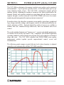
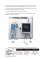
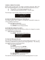
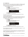
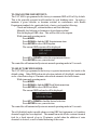
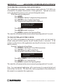
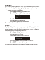
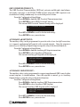
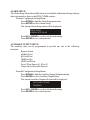
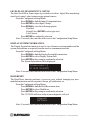
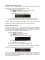
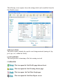
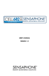
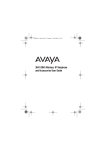
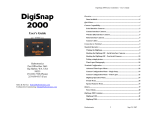
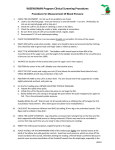
CAT 4000
WATER QUALITY CONTROLLER
OWNER'S MANUAL
INSTALLATION
OPERATION
MAINTENANCE
SPECIFICATIONS
FOREWORD
_
Congratulations on your wise investment and welcome to the world of
wireless, web-enabled water quality management. The CAT 4000 chemical
automation system has been engineered to provide you with substantially
reduced chemical costs and maintenance, improved water quality, increased
compliance with Health Department operating standards, and many years of
reliable operation.
All CAT controllers incorporate state of the art
microprocessor-based design technology to provide sophisticated control
functions at an affordable price. The CAT 4000 additionally provides wireless
communications capability for web-based monitoring, management and
notification through the POOLCOMM website.
Although CAT controllers are relatively simple to install, please take the time to
read this entire manual, inspect package contents, and gather all tools
required before beginning installation. Improper installation may void the
warranty and create unnecessary hazards. Properly preparing for installation
will also reduce facility down-time.
If this system is to be used with the POOLCOMM water quality management
website it is important to determine that wireless service coverage is available
at the installation location. CAT Controllers tech support team will be happy to
determine coverage options for your location.
For the purposes of this manual, it is presupposed that the installer is familiar
with the physical characteristics of the pool or spa to be automated. As is the
case when installing any filtration system component, all recirculating pumps,
heaters, etc. need to be turned off prior to installation of the controller. If the
filtration system is located below water level, additionally adjust all valves
required to eliminate pressure from the system.
Physically, installation of a CAT controller is no more challenging than
installation of a chemical feeder. Any swimming pool contractor or
maintenance engineer should have the tools and knowledge to perform the
installation. Our technical support line can also be used to answer any
questions pertaining to controller installation.
Congratulations on your purchase and welcome to the world of chemical
automation and wireless water quality management. Please complete your
warranty registration at your earliest convenience.
CONTENTS COPYRIGHT 2010 HAYWARD INDUSTRIES, INC. ALL RIGHTS RESERVED
TABLE OF CONTENTS
Section 1. Water Quality Control with the CAT 4000
Section 2. CAT 4000 System Components
Section 3. Important Safety Information
Section 4. Package Contents
Section 5. System Installation
Section 6. Preparing Water Chemistry
Section 7. CAT 4000 Setup & Programming
Section 8. Advanced Configuration Options
Section 9. CAT 4000 Menu Tree
Section 10. Maintenance
Section 11. Testing for Network Coverage
Section 12. Activating Wireless Communications
Section 13. Using the POOLCOMM Website
Section 14. Notifications to Cell Phones
Section 15. Alarm Troubleshooting
Section 16. Specifications
Section 17. Warranty
_
SECTION 1.
WATER QUALITY with the CAT 4000
The CAT 4000 revolutionizes the manner in which water quality can be monitored
and maintained. A pool operator typically checks, records and adjusts pool or spa
water chemistry hourly at best. The CAT 4000 continuously samples pH and
sanitizer activity, adjusting the feeding of chemicals on a basis proportional to the
demand. Hourly water quality readings are sent along with any alarms or service
requests through a wireless network to the POOLCOMM web server for remote
1
monitoring and management through any internet connection.
From the website, the subscriber can monitor water quality, print charts, graphs and
logs, change controller settings, and designate contacts for outbound notification via
email, cell phone or PDA. Optional digital flow and level sensors are available to
monitor flow rate, chemical storage tank levels, and even automate water level
control.
The results include elimination of "human error", accurate and reliable maintenance
of chemical levels twenty-four hours a day, compliance with Health Department
operating standards, reduced burden on operating staff, and a reduction of chemical
usage and costs. The CAT 4000 controller and POOLCOMM water quality
management website together provide unprecedented control, access and
documentation.
The following graph compares typical chlorine levels when chemistry is adjusted
manually versus automatically with the CAT 4000 controller:
1
The POOLCOMM website is a subscription based service. Monthly charges apply.
CONTENTS COPYRIGHT 2010 HAYWARD INDUSTRIES, INC. ALL RIGHTS RESERVED
SECTION 2.
CAT 4000 SYSTEM COMPONENTS
The following is a description of the components incorporated in a typical CAT 4000
wireless water quality control system:
The Professional-Series pH Sensor samples water from the filtration system and
sends signals to the controller indicating the acidity of the water. The ideal pH range
for pools and spas is 7.4 - 7.6. The CAT 4000 controller is preset from the factory to
maintain pH 7.5. If pH is maintained below 7.4 (too acidic), eye irritation, corrosion
of equipment, and damage to the pool or spa surface can occur. If pH is maintained
above 7.6 (too alkaline), sanitizer activity is reduced, water may become cloudy, and
eye irritation may result.
The Professional-Series ORP Sensor samples water from the filtration system and
sends signals to the controller indicating the oxidation-reduction potential (redox) of
the water. ORP is an actual measure of sanitizer activity (chlorine, bromine, ozone,
etc.) and bacteriological water quality rather than an expression of chemical
residual levels. The CAT 4000 controller is preset from the factory to maintain ORP
at 650 millivolts.
The Flow Sensor monitors the rate of flow across the pH and ORP sensors and
signals the controller to disable automated chemical feeding during periods when the
filtration system is off or low recirculation flow is detected.
The Flow Cell provides a convenient location for mounting the pH, ORP and Flow
sensors while ensuring ideal hydraulic conditions to maximize sensor performance
and life.
The CAT 4000 Controller scans and interprets the signals from the pH, ORP, flow,
and optional digital flow-rate and level sensors, displays water quality readings and
alarms in alphanumeric format, and activates chemical feeders in proportion to
demand to maintain pH and ORP setpoint levels.
The controller incorporates audible and visual safeguard alarms for out of range
conditions and menu-driven control of setpoints, alarms, and a host of advanced
features. The CAT 4000 controller also features an internal transceiver for wireless
transmission of data between the controller and POOLCOMM website.
The Level Sensors (optional) provide signals to the controller indicating low pH
chemical tank level, low ORP tank level, and low water level.
The Digital Flow Sensor (optional) provides a flow rate to be displayed by the
controller and an alarm indication when filter maintenance is required.
SECTION 3.
IMPORTANT SAFETY INFORMATION
IMPORTANT SAFETY INFORMATION
1. WARNING - Important safety information is contained throughout this manual.
Read complete instructions prior to installation.
2. WARNING - Risk of Electric Shock. Connect controller only to a grounding type
receptacle protected by a ground-fault circuit interrupter (GFI). CAT Controllers
recommends installation to a dedicated GFI circuit breaker performed by a licensed
electrician.
3. WARNING - Disconnect power before servicing. Other than the fuses, there are
no user serviceable parts inside the controller.
4. WARNING - All power cords should be inspected frequently. Any damaged
power cords must be replaced immediately to reduce the risk of electric shock.
Never operate a controller without functional flow protection.
5. WARNING - Installation requires a properly located GFI protected receptacle.
Never use an extension cord for electrical connections to the controller.
6. WARNING - Always mount controller in a safe area not subject to damage by
moving objects. Never bury controller power cords.
7. WARNING - Any person using, adjusting, or monitoring the controller must be at
least 18 years of age and be familiar with these instructions and the contents of this
manual.
8. WARNING - Always take and record manual water chemistry readings in
conformance with Health Department requirements.
Although automated
controllers are a great aid in maintaining healthy water quality, controllers are not a
substitute for manual water testing with an accurate test-kit.
9. WARNING - Always read and become familiar with Material Safety Data Sheets
(MSDS) and safe handling instructions for all chemicals used with the controller.
10. Caution: The automatic controller should not be installed where it is accessible to
the public.
CONTENTS COPYRIGHT 2010 HAYWARD INDUSTRIES, INC. ALL RIGHTS RESERVED
SECTION 4.
PACKAGE CONTENTS
Please unpack your new controller system carefully. Do not use a razor or
sharp instrument to remove contents. Report any shipping or handling
damage immediately to your shipping company. Enclosed in the packaging
you should find all of the following:
(1)
CAT 4000 Wireless Water Quality Controller1
(1)
PVC Backboard with Mounting Holes and Stainless Hardware
(1)
Professional Series pH Sensor with 24” Cable and BNC Connector
(1)
Professional Series ORP Sensor with 24” Cable and BNC Connector
(2)
Sensor Storage Containers
(1)
Injection Molded Flow Cell
(3)
1/4” NPT x 3/8” Tubing True-Seal Ball Valve
(1)
Flow Switch with 24” Cable and Specialty Connector1
(2)
BNC Connector Protective Covers (Remove to Connect Sensors)
(1)
30’ Roll, Blue Poly Installation Tubing (3/8” OD)
(2)
1/4” NPT x 3/8” Tubing True-Seal Connectors
(1)
CAT 4000 Quick Reference Guide
1
1
1
Before commencing installation, please confirm that items listed above have
been included. Please report any shortages immediately to the factory.
1
Denotes items assembled at the factory.
SECTION 5.
SYSTEM INSTALLATION
The following tools are recommended for installation:
Drill (Cordless preferred)
3/8" Drill Bit
1/4" NPT (National Pipe Tapered) Tap
Masonry Drill Bit & Anchors (if required)
13/16” Wrench or Channel-Lock Pliers.
INSTALLATION PROCEDURES
The key to a successful flow cell installation is in the plumbing. A pressure
differential is required to allow clean, untreated water to pass through the cell and
across the sensors. We recommend using the enclosed tubing and fittings to create a
pressure-suction “loop” line.
1. Turn off heater, chemical feeders, pump, and any other related equipment.
Relieve pressure from filtration system.
2. Select a convenient mounting location for the controller unit which will meet the
following criteria:
A. Facilitates a combined (influent and effluent) maximum tubing run of 30’.
B. Located a minimum of ten feet from pool or spa.
C. GFI protected power source available.
D. Easily accessible to pool or spa operator.
E. Away from corrosive materials and physical hazards.
3. Securely mount PVC Backboard on vertical wall.
4. Drill and tap a 1/4” NPT port at a location just down-stream of the filter, but upstream from any chemical injection point. Install a tubing connector, and run flex
tubing to the influent flow cell port.
5. Drill and tap a 1/4” NPT port at a location subject to vacuum or reduced pressure.
Install the remaining tubing connector and run flex tubing to the effluent flow cell
port.
6. Cut a 3” length of flex tubing and insert into the sample stream port.
7. Remove pH and ORP sensors from the plastic storage bottles and save bottles and
storage fluid for future use. Thread sensors into flow cell.
8. Remove BNC protective covers from left side of controller unit and store for
future use. These covers protect the controller unit from electro-static discharge
(ESD) and should be used whenever handling or transporting the controller unit.
CONTENTS COPYRIGHT 2010 HAYWARD INDUSTRIES, INC. ALL RIGHTS RESERVED
9. Connect the pH, ORP and Flow sensor cables to the controller unit as labeled.
Sensor cables are constructed from a specialized material - never cut or splice.
10. If new or additional chemical feeders are to be used with the controller, install
according to manufacturers instructions at this time.
11. Connect chemical feeders to the controller as labeled.
12. Check all electrical and mechanical connections. Resume filtration system
operation and check for any leaks.
INFLUENT
EFFLUENT
SAMPLE
STREAM
pH
FEED
POWER
CORD
ORP
FEED
WORKING WITH TRU-SEAL FLUID CONNECTIONS FOR A FAST, PROFESSIONAL INSTALLATION
BODY
O-RING
COLLET
TUBING
Prepare Tubing:
Insert Tubing
Cut tubing squarely
and remove any
burrs. Mark tubing
3/4" from end. This
is the insertion mark.
Insert tubing straight
into fitting until it
bottoms out and
insertion mark is no
longer visible.
To Release Tubing:
Push collet toward
fitting body and pull
on tubing to release.
Repeat steps 1 and 2
to reuse fitting.
CONTENTS COPYRIGHT 2010 HAYWARD INDUSTRIES, INC. ALL RIGHTS RESERVED
Flow
SUCTION LINE
Main Drain
and Skimmer
Influent
(to Return Line)
pH
pH
CAT PR015
SENSOR
ORP
SENSOR
Flow
Sample
Stream
ORP
CAT PR025
UP
POOLCOMM
MENU
PUMP
Flow
ENTER
TRANSMIT
pH
Cl/Br
Feed
Alarm
Feed
Chemical
Pump
Power Cord
or
CAT CO2
pH Control
Flow
FILTER
Flow Cell / Flow Sensor Bypass Line
ORP Feed Output
CAT 4000
SYSTEM
pH Feed Output
Chemical Automation Technologies
DOWN
POOLCOMM
CAT 4000 Water Quality Controller
Effluent
(to Suction)
Flow
ORP
pH
WATER QUALITY MANAGEMENT
POOLCOMM
Flow
Flow
RETURN LINE
WASTE
Solenoid
TYPICAL CAT 4000 INSTALLATION DIAGRAM
Pressure
Differential
Solenoid
Erosion
Feeder
or
Chemical
Pump
SECTION 6.
PREPARING WATER CHEMISTRY
Now that your new controller has been physically installed, water chemistry should
be tested and adjusted prior to initiating automated control of the pool or spa.
Confirm that your pool or spa water conforms to the following ranges before
powering on and setting up the CAT 4000.
TEST
MINIMUM
IDEAL
MAXIMUM
pH
7.2
7.5
7.8
Free Chlorine (PPM)
1
2
3
2
3
4
Cyanuric Acid (PPM)
0
-
100
ORP (mV)
650
-
-
Total Alkalinity
80
-
120
Calcium Hardness
200
-
400
Bromine (PPM)
The above table indicates generally accepted guidelines. Always maintain water
chemistry according to standards set by your local or State Health Department.
All CAT water quality controllers maintain sanitizer levels (chlorine, bromine,
ozone, etc.) based on ORP. Although ORP is a superior index of water quality
compared to part per million sanitizer residual levels, factors such as pH, cyanuric
acid concentration and total dissolved solids can affect sanitizer residual readings
relative to ORP.
CAT Controllers, Inc. recommends establishing desired pH, sanitizer residual,
calcium hardness, total alkalinity, temperature and cyanuric acid levels prior to
initiating automated control of the pool or spa. The ORP setpoint will need to be
changed periodically as described later in this section if the goal is to provide
consistent sanitizer residual levels rather than consistent control of ORP.
SECTION 7.
CAT 4000 SETUP & PROGRAMMING
The CAT 4000 features a bright, menu-driven vacuum-flourescent display which
makes setup and programming simple in any lighting conditions. The menu
structure is divided into two sections; the Operating Menu is intended for the enduser to manage settings which are accessed on a frequent basis, while the
Configuration Menu is used to setup advanced features which truly customize the
controller to meet the individual requirements of the application.
The keypad provides intuitive access to the controller functionality as described
below:
MENU
UP
DOWN
ENTER
TRANSMIT
MENU
Used to enter menu mode and to navigate back within the
menu structure.
UP
Used to increase values and to navigate vertically up
within the menu structure.
DOWN
Used to decrease values and to navigate vertically down
within the menu structures
ENTER
Used to select or confirm a menu item.
TRANSMIT
Sends a Service Request alarm and current data to the
POOLCOMM web server.
CONTENTS COPYRIGHT 2010 HAYWARD INDUSTRIES, INC. ALL RIGHTS RESERVED
NORMAL OPERATING MODE:
During normal operating mode, the display will indicate sensed pH, ORP, Flow
Rate (with optional digital flow sensor) and a status line which alternates between:
A)
“System OK” or a list of any alarm conditions, and
B)
A graph indicating sensed pH and ORP vs- setpoint values.
The following is a typical display during normal operating mode:
pH 7.5 ORP 650
System OK
TO CHANGE THE BRIGHTNESS OF THE DISPLAY:
The display intensity can be changed to accommodate comfortable viewing in a
variety of lighting circumstances.
While in normal operating mode:
Press UP to increase display intensity.
Press DOWN to decrease display intensity.
TO ENTER THE OPERATING MENU:
The operating menu contains selections which are likely to be changed on a routine
basis, and therefore are easily accesed.
While in normal operating mode:
Press MENU. The following will be displayed:
Operating Menu
pH Setpoint
TO CHANGE THE pH SETPOINT:
The CAT 4000 is programmed at the factory with a default setpoint of pH 7.5. CAT
Controllers considers this to be ideal for pool and spa applications. The following
steps enable the selection of a different setpoint.
While in normal operating mode:
Press MENU.
Select pH setpoint by pressing ENTER.
The current pH setpoint will be displayed:
pH Setpoint
7.5 pH
Press UP or DOWN to select the desired pH.
Press ENTER to save your selection.
The controller will automatically return to normal operating mode in 10 seconds.
TO CALIBRATE pH:
The CAT 4000 is far more accurate than most liquid test standards, but pH
calibration is necessary to match manual water testing results, compensate for a
depleted or unclean pH sensor, and confirm proper operation of the system.
While in normal operating mode:
Press MENU.
Press DOWN to find the pH Calibrate menu item.
Press ENTER to select pH Calibrate.
The sensed pH value as currently calibrated will be displayed:
pH Calibrate
7.5 pH
Press UP or DOWN match your known good standard.
Press ENTER to save your selection.
The controller will automatically return to normal operating mode in 10 seconds.
TO SELECT pH FEED MODE:
The CAT 4000 is programmed at the factory to operate in automatic feed mode as the
default setting. Other pH feed mode selections include off (disabled), and manual on
for a fixed interval up to 25 minutes after which automatic feed will resume.
While in normal operating mode:
Press MENU.
Press DOWN to find the pH Feed Mode menu item.
Press ENTER to select pH Feed Mode.
The current pH feed mode will be displayed:
pH Feed Mode
Automatic Feed
Press UP or DOWN to find the desired selection.
Press ENTER to save your selection.
The controller will automatically return to normal operating mode in 10 seconds.
The off (disabled) mode is useful when servicing pH feed equipment, or if pH
chemical supply has been depleted.
The manual on mode allows constant chemical feed for a fixed interval of up to 25
minutes. This feature is useful when the addition of extra chemicals is desired, as
well as during initial balancing of the water.
Note: Always disconnect chemical feeder power cords prior to performing any
electrical service.
CONTENTS COPYRIGHT 2010 HAYWARD INDUSTRIES, INC. ALL RIGHTS RESERVED
TO CHANGE THE ORP SETPOINT:
The CAT 4000 is programmed at the factory to maintain ORP at 650 mV by default.
This is the generally accepted world standard for safe drinking water. In order to
maintain a given chlorine or bromine residual in conformance with Health
Department standards for a particular body of water, perform the following:
Check and balance pH, calcium hardness and total alkalinity.
Manually feed chlorine or bromine to desired ppm residual.
Note the displayed ORP value. This will be used as the setpoint.
While in normal operating mode:
Press MENU.
Press DOWN to find the ORP Setpoint menu item.
Press ENTER to select ORP Setpoint.
The current ORP setpoint will be displayed:
ORP Setpoint
650 mV
Press UP or DOWN to select the setpoint noted above.
Press ENTER to save your selection.
The controller will automatically return to normal operating mode in 10 seconds.
TO SELECT ORP FEED MODE:
The CAT 4000 is programmed at the factory to operate in automatic feed mode as the
default setting. Other ORP feed mode selections include off (disabled), and manual
on for a fixed interval up to 25 minutes after which automatic feed will resume.
While in normal operating mode:
Press MENU.
Press DOWN to find the ORP Feed Mode menu item.
Press ENTER to select ORP Feed Mode.
The current ORP feed mode will be displayed:
ORP Feed Mode
Automatic Feed
Press UP or DOWN to find the desired selection.
Press ENTER to save your selection.
The controller will automatically return to normal operating mode in 10 seconds.
The off (disabled) mode is useful when servicing ORP feed equipment, or if sanitizer
chemical supply has been depleted. The manual on mode allows constant chemical
feed for a fixed interval of up to 25 minutes, useful when the addition of extra
chemicals is desired, as well as initial balancing of the water.
SECTION 8.
ADVANCED CONFIGURATION OPTIONS
TO ENTER THE CONFIGURATION SETUP MENU:
The configuration setup menu contains features which enable the CAT 4000 to be
customized to the unique characteristics of the application. Optional accessories
such as the digital flow meter are also activated through this menu.
While in normal operating mode:
Press MENU.
Press DOWN to find the Configuration Setup menu item.
Press ENTER to select Configuration Setup.
The Configuration Setup Menu will be displayed:
Configuration Setup
pH Control Mode
Press DOWN to scroll through menu items.
Press ENTER to make a selection.
Press MENU to return to the Operating Menu.
The controller will automatically return to normal operating mode in 10 seconds.
TO CHANGE THE pH CONTROL MODE:
The CAT 4000 is programmed at the factory to operate in the acid feed mode by
default (when pH exceeds setpoint, the pH chemical feeder is activated). If the
sanitizer or other factors of the application cause the pH to decrease, base feed mode
must be selected.
From the Configuration Setup Menu:
Press DOWN to find the pH Control Mode menu item.
Press ENTER to select pH Control Mode.
The current pH Control Mode will be displayed:
pH Control Mode
Acid Feed
Press UP or DOWN to select acid feed or base feed.
Press ENTER to save your selection.
Press MENU to return to the Operating Menu.
The controller will automatically return to normal operating mode in 10 seconds.
Note: In certain unusual applications, pH correction may be required in both acid
feed and base feed modes. The third relay can be programmed as described later in
this manual to accommodate this requirement.
CONTENTS COPYRIGHT 2010 HAYWARD INDUSTRIES, INC. ALL RIGHTS RESERVED
pH PRIORITY:
The CAT 4000 features a pH Priority setting which will inhibit ORP feed whenever
pH is greater than .2 pH from the setpoint. This feature provides an important
safeguard when sanitizers with a high pH (such as liquid chlorine) are used.
From the Configuration Setup Menu:
Press DOWN to find the pH Priority menu item.
Press ENTER to select pH Priority.
The current pH Priority Mode will be displayed:
pH Priority
Off
Press UP or DOWN to enable or disable pH Priority.
Press ENTER to save your selection.
Press MENU to return to the Operating Menu.
The controller will automatically return to normal operating mode in 10 seconds.
pH FEED:
The CAT 4000 by default uses a time-based proportional feed algorithm which
enables the control of virtually any body of water without under-feeding or overshooting the setpoint. With some types of chemical feeders, however, it is beneficial
to disable proportional feed and feed on a fixed basis.
From the Configuration Setup Menu:
Press DOWN to find the pH Feed menu item.
Press ENTER to select pH Feed.
The current pH Feed setting will be displayed:
pH Feed
Proportional
Press UP or DOWN to select Proportional or Fixed feed.
Press ENTER to save your selection.
Press MENU to return to the Operating Menu.
The controller will automatically return to normal operating mode in 10 seconds.
pH LOW ALARM:
The pH Low Alarm inhibits pH feed, sounds audible and visual alarms, and sends a
message to the POOLCOMM website during a low pH condition.
From the Configuration Setup Menu:
Press DOWN to find the pH Low Alarm menu item.
Press ENTER to select pH Low Alarm.
The current pH Low Alarm Setting will be displayed:
pH Low Alarm
7.0 pH
Press UP or DOWN to scroll to the desired setting.
Press ENTER to save your selection.
Press MENU to return to the Operating Menu.
pH HIGH ALARM:
The pH High Alarm inhibits pH feed, sounds audible and visual alarms, and sends a
message to the POOLCOMM website during a high pH condition.
From the Configuration Setup Menu:
Press DOWN to find the pH High Alarm menu item.
Press ENTER to select pH High Alarm.
The current pH High Alarm Setting will be displayed:
pH High Alarm
8.0 pH
Press UP or DOWN to scroll to the desired setting.
Press ENTER to save your selection.
Press MENU to return to the Operating Menu.
pH OVERFEED TIMEOUT:
The pH Overfeed Timeout inhibits pH feed, sounds audible and visual alarms, and
sends a message to the POOLCOMM website when the pH setpoint is not reached
after feeding continuously for a selectable period of time.
From the Configuration Setup Menu:
Press DOWN to find the pH Overfeed Timeout menu item.
Press ENTER to select pH Overfeed Timeout.
The current pH Overfeed Timeout Setting will be displayed:
pH Overfeed Timeout
Off
Press UP or DOWN to scroll to the desired setting.
Press ENTER to save your selection.
Press MENU to return to the Operating Menu.
CONTENTS COPYRIGHT 2010 HAYWARD INDUSTRIES, INC. ALL RIGHTS RESERVED
ORP FEED:
The CAT 4000 by default uses a time-based proportional feed algorithm which
enables the precise control of virtually any body of water. With some types of
chemical feeders, however, it is beneficial to disable proportional feed and dispense
chemicals on a fixed basis.
From the Configuration Setup Menu:
Press DOWN to find the ORP Feed menu item.
Press ENTER to select ORP Feed.
The current ORP Feed setting will be displayed:
ORP Feed
Proportional
Press UP or DOWN to select Proportional or Fixed feed.
Press ENTER to save your selection.
ORP LOW ALARM:
The ORP Low Alarm inhibits ORP feed, sounds audible and visual alarms, and
sends a message to the POOLCOMM website during a low ORP condition.
From the Configuration Setup Menu:
Press DOWN to find the ORP Low Alarm menu item.
Press ENTER to select ORP Low Alarm.
The current ORP Low Alarm Setting will be displayed:
ORP Low Alarm
400 mV
Press UP or DOWN to scroll to the desired setting.
Press ENTER to save your selection.
ORP HIGH ALARM:
The ORP High Alarm inhibits ORP feed, sounds audible and visual alarms, and
sends a message to the POOLCOMM website during a high ORP condition.
From the Configuration Setup Menu:
Press DOWN to find the ORP High Alarm menu item.
Press ENTER to select ORP High Alarm.
The current ORP High Alarm Setting will be displayed:
ORP High Alarm
900 mV
Press UP or DOWN to scroll to the desired setting.
Press ENTER to save your selection.
ORP OVERFEED TIMEOUT:
The ORP Overfeed Timeout inhibits ORP feed, activates audible and visual alarms,
and sends a message to the POOLCOMM website when the ORP setpoint is not
reached after feeding continuously for a selectable period of time.
From the Configuration Setup Menu:
Press DOWN to find the ORP Overfeed Timeout menu item.
Press ENTER to select ORP Overfeed Timeout.
The current ORP Overfeed Timeout Setting will be displayed:
ORP Overfeed Timeout
Off
Press UP or DOWN to scroll to the desired setting.
Press ENTER to save your selection.
AUXILIARY pH SETPOINT:
The auxiliary relay can be programmed to provide acid or base feed pH correction,
or to support supplemental pH control with a second setpoint. Once the setpoint is
entered, go to Auxiliary Output Setup to assign the relay to the desired function.
From the Configuration Setup Menu:
Press DOWN to find the Auxiliary pH Setpoint menu item.
Press ENTER to select Auxiliary pH Setpoint.
The current Auxiliary pH Setpoint will be displayed:
AUX pH Setpoint
7.5 pH
Press UP or DOWN to scroll to the desired setting.
Press ENTER to save your selection.
AUXILIARY ORP SETPOINT:
The auxiliary relay can be programmed to support supplemental ORP control with a
second setpoint, or dechlorination. Once the setpoint is entered, go to Auxiliary
Output Setup to assign the relay to the desired function.
From the Configuration Setup Menu:
Press DOWN to find the Auxiliary ORP Setpoint menu item.
Press ENTER to select Auxiliary ORP Setpoint.
The current Auxiliary ORP Setpoint will be displayed:
AUX ORP Setpoint
650 mV
Press UP or DOWN to scroll to the desired setting.
Press ENTER to save your selection.
CONTENTS COPYRIGHT 2010 HAYWARD INDUSTRIES, INC. ALL RIGHTS RESERVED
ALARM SETUP:
The Alarm Setup allows the audible alarm to be disabled without interfering with any
other safeguards or alerts to the POOLCOMM website.
From the Configuration Setup Menu:
Press DOWN to find the Alarm Setup menu item.
Press ENTER to select Alarm Setup.
The current Alarm Setup option will be displayed:
Alarm Setup
Audible and Visual
Press UP or DOWN to scroll to the desired setting.
Press ENTER to save your selection.
AUXILIARY OUTPUT SETUP:
The auxiliary relay can be programmed to provide any one of the following
functions:
Remote Alarm
pH Base Feed
pH Acid Feed
ORP Feed Up
ORP Feed Down
Level / Flow Sensor #1, #2 or #3
Timer On for Selectable Interval
From the Configuration Setup Menu:
Press DOWN to find the Auxiliary Output Setup menu item.
Press ENTER to select Auxiliary Output Setup.
The current Auxiliary Output selection will be displayed:
AUX Output Setup
Disabled
Press UP or DOWN to scroll to the desired setting.
Press ENTER to save your selection.
LEVEL/FLOW SENSOR INPUT # 3 SETUP:
The third Level/Flow Sensor input is provided to facilitate, digital flow monitoring
water level control, other features using optional sensors.
From the Configuration Setup Menu:
Press DOWN to find the Input 3 Setup menu item.
Press ENTER to select Input 3 Setup.
Press DOWN to view the following options:
Disabled
Digital Flow (ENTER to select pipe size).
Level Sensor
Press ENTER to confirm the selection.
After 10 seconds, the controller will revert to the Configuration Setup Menu.
DISPLAY SYSTEM INFORMATION:
The Display System Info function is used to view firmware revision number and the
system date and time as acquired from the wireless communications link.
From the Configuration Setup Menu:
Press DOWN to find the Display System Info menu item.
Press ENTER to select Display System Info.
Press ENTER at the prompt to confirm the selection.
The System Information will be displayed:
firmware version 1.8
07-12-05 13:22 (UTC)
After 10 seconds, the controller will revert to the Configuration Setup Menu.
HARD RESET:
The Hard Reset function performs a power-on reset without changing any usermodified menu items such as setpoints, alarms, pH calibration, etc.
From the Configuration Setup Menu:
Press DOWN to find the Hard Reset menu item.
Press ENTER to select Hard Reset.
Press ENTER at the prompt to confirm the selection.
The CAT 4000 will reset and perform a diagnostic self-test:
Diagnostic
Self Check
After 10 seconds, the controller will revert to the Configuration Setup Menu.
CONTENTS COPYRIGHT 2010 HAYWARD INDUSTRIES, INC. ALL RIGHTS RESERVED
RESTORE FACTORY DEFAULTS:
The Restore Factory Defaults function erases all user-modified settings from
memory and restores all factory default settings and values.
From the Configuration Setup Menu:
Press DOWN to find the Restore Factory Def. menu item.
Press ENTER to select Restore Factory Def.
Press ENTER again at the following prompt:
Restore Factory Def.
ENTER to Restore....
The display will go blank, and all default settings will be restored.
After 10 seconds, the controller will revert to the Normal Operating Mode
Caution: all user modified settings including acid/base feed mode, alarms,
setpoints, etc must now be configured as described earlier in this manual.
DEMONSTRATION MODE:
The Demo Mode enables the CAT 4000 to be used as a demonstration, training, or
sales aid. All functions, menus, and settings of the controller are active except that
pH is simulated at 7.5 and ORP is simulated at 650 mV. Therefore, no sensors are
required when working with the controller in Demo Mode.
From the Configuration Setup Menu:
Press DOWN to find the Demo menu item.
Press ENTER to select Demo.
The current status of Demo Mode will be displayed:
Demo
Off
Press UP or DOWN to make a selection.
Press ENTER to save your selection.
The controller will revert to the Configuration Setup Menu.
As a reminder that the controller is in Demonstration Mode, the following
screen will be alternately displayed when in Normal Operating Mode:
CAT 4000
Demo Mode
Caution: Demonstration Mode must never be used when the CAT 4000 is connected
to active chemical feeders or otherwise in use as a water quality controller. The
CAT 4000 is simulating pH and ORP values, and therefore is not sampling the
sensors or monitoring water quality.
SECTION 9.
CAT 4000 MENU TREE
Default Operating Mode
pH Setpoint
7.0 to 8.0
(Default 7.5)
pH Calibrate
Plus or Minus 2.0 pH
pH Feed Mode
Automatic Off
On for Specified Time
ORP Setpoint
400 to 900 mV
(Default 650 mV)
ORP Feed Mode Automatic Off
On for Specified Time
Configuration Setup Menu
pH Control Mode
Acid Feed Base Feed
pH Priority
Off
pH Feed
ProportionalFixed
pH Low Alarm
0.0 to 14.0 Default 7.0 pH
pH High Alarm
0.0 to 14.0 Default 8.0 pH
pH Overfeed Timer
Off, 5 to 120 Minutes (Default 120 Min.)
ORP Feed
Proportional or Fixed
ORP Low Alarm
0 to 995 mV
ORP High Alarm
0 to 995 mV
ORP Overfeed Timer
Off, 5 to 120 Minutes (Default 120 Min.)
Aux pH Setpoint
0.0 to 14.0 Default 7.5
Aux ORP Setpoint
400 to 995 mV
Alarm Setup
Audible and Visual, Visual Only
On
Default 400 mV
Default 900 mV
Default 650 mV
CONTENTS COPYRIGHT 2010 HAYWARD INDUSTRIES, INC. ALL RIGHTS RESERVED
Default Operating Mode
Configuration Setup Menu
AUX Output Setup
Disabled
Remote Alarm
pH Base Feed
pH Acid Feed
ORP Feed Up
ORP Feed Down
pH Level/Flow Sensor
ORP Level/Flow Sensor
Level/Flow Sensor #3
On for Specified Time
1 to 30 Minutes
Level/Flow Input #3 Setup
Disabled, Digital Flow, Level
Digital Flow Pipe Size
3/8" to 12", 50mm to 315mm
Digital Flow Alarm
Select Alarm Flow Rate
Display System Information
ENTER to Display
Hard Reset
ENTER to Reset
Restore Factory Defaults
Enter to Restore
Demonstration Mode
Off, On
SECTION 10.
MAINTENANCE
CAT 4000 CONTROLLER PACKAGE
The CAT 4000 controller unit is virtually maintenance free. Cleaning of the
enclosure, front panel and flow cell can be performed using a clean, soft cloth
moistened with mild soap and water solution or glass cleaner. Use of abrasives or
harsh chemicals may damage the enclosure and membrane switch panel.
WATER MAINTENANCE
Always test and record water chemistry readings in compliance with Health
Department requirements using a quality manual test kit. Calibrate pH periodically
as described earlier in this manual.
It is important to note that changes in pH, cyanuric acid concentration, total
dissolved solids, and use of additional or alternative sanitizers will all affect the
primary sanitizer residual level relative to ORP. It is important to maintain total
alkalinity on a regular basis to ensure pH stability. To maintain a consistent sanitizer
residual in parts-per-million (ppm), periodically adjust the ORP setpoint.
PRECISION CALIBRATION
The CAT 4000 controller provides instrument-grade accuracy which exceeds that of
most liquid-standard water testing kits. Therefore, it may be preferable to calibrate
pH using commercially available reference solutions.
SENSOR MAINTENANCE
The sensors must be clean and free from oil, chemical deposits and contamination to
function properly. After saturation in pool or spa water, the sensors may need to be
cleaned on a weekly or monthly basis depending on bather load and other facilityspecific characteristics. Slow response, increased need to calibrate pH, and
inconsistent readings are indications that the sensors are in need of cleaning.
To clean the sensors, disconnect from the controller and carefully remove them from
the flow cell. Clean the reference junction (the white teflon ring at the bottom of
sensor body) with a soft tooth brush and regular tooth paste. A household liquid
dishwashing detergent may also be used to remove any oil. Rinse with fresh water,
replace teflon thread-seal tape, and reinstall sensors.
SENSOR REPLACEMENT
CAT Professional Series pH and ORP sensors are engineered to provide the highest
performance and longest possible functional service life. If properly cleaned
sensors provide unstable readings or require excessive calibration, the pair of
sensors should be replaced. For optimum controller performance, replace with
genuine CAT Professional Series sensors PRO15-2 and PRO25-2.
CONTENTS COPYRIGHT 2010 HAYWARD INDUSTRIES, INC. ALL RIGHTS RESERVED
SENSOR STORAGE
Exposure to atmospheric conditions will cause the sensor tips to dry out. Always
remove and properly store sensors in the soaking caps provided if sensors are to be
removed or stored for one hour or longer. Although CAT Professional Series
sensors are freeze-resistant, they must be protected from freezing temperatures
when not in use.
Store sensors in the soaking caps provided, making sure that each container is filled
with the original storage solution or clean water. If the storage containers have been
misplaced, store sensors individually in small glass or plastic containers with clean
water covering sensor tips.
CONTROLLER STORAGE
The controller unit is subject to damage by electro-static discharge (ESD) when the
sensor cables are disconnected. Always reinstall the BNC protective covers prior to
storing or transporting the CAT 4000controller unit.
WINTERIZATION
The sensors should be prepared for storage as outlined above and protected from
freezing temperatures. Although the CAT 4000 controller is designed to withstand a
broad temperature range, winter storage in a secure location may be desirable.
The flow cell and poly tubing must be drained prior to exposure to freezing
temperatures. Either purge all water using compressed air or thoroughly drain
through the valve ports and tubing connections.
SECTION 11.
TESTING FOR NETWORK COVERAGE
Check the Coverage Map
CAT can provide a printed or electronic copy of the Reflex coverage map in
your state. Please contact the POOLCOMM Program Administrator.
Check the Web Site
Visit the Sky-Tel web site and enter the exact address of the facility to be
monitored. The web site will pin point that address on a custom coverage map.
Start by entering www.skytel.com into your web browser. Next select
Telemetry then Coverage and enter the address to check, select locate. The CAT
400 requires full service (Shown as Yellow) to send and receive data.
Direct Link= www.skytel.com/coverage/telemetry_coverage.htm
Test with a Portable Reflex Device
The Reflex network can be tested with any number of portable 2-way messaging
devices, such as: Skywriter, Blackberry, or and 2-way pager. To learn more or
to purchase one of these devices visit www.skytel.com. Portable 2-way devices
operate at about half the broadcast power output of the CAT 4000. Therefore, if
you portable device has full service the CAT 4000 will definitely work well in
that location. However, the CAT 4000 will communicate in locations a portable
does not.
Test w/ a CAT 4000
The best way to check for Reflex coverage at a facility is to test with an actual
CAT 4000. The Transmit data button has been provided specifically for this
purpose. Place the CAT 4000 unit where you expect to install it and press the
transmit data button. Within 2 minutes a service request alarm will be generated.
This alarm will show up at the POOLCOMM web site, and can also be directed
to your cell phone or portable 2-way device. Make sure your email address has
been entered under Notifications and that address box is checked on the unit
management page.
Secondary Carrier
If you find your client location does not have Skytel coverage contact the
POOLCOMM Program Manager for secondary carrier availability.
CONTENTS COPYRIGHT 2010 HAYWARD INDUSTRIES, INC. ALL RIGHTS RESERVED
SECTION 12.
ACTIVATING COMMUNICATIONS
To activate your first CAT 4000 wireless controller on the POOLCOMM web
site you must first register an account. Call 800-657-2287 and ask for the
POOLCOMM Program Administrator if you need assistance.
Visit www.poolcomm.com from any internet-connected computer. Click on
Register Account and complete all requested account information. Click on
Register Account again to register with the system.
The next screen will then inform you that your account has been created and an
email has been sent to you with your User Name and Password. You may now
login to your account by typing your username and password, then clicking on
the Login icon.
The Register Account Unit screen will now appear. Enter the requested
information and click on Register Unit to begin accessing your CAT 4000 over
the internet.
SECTION 13.
USING THE POOLCOMM WEBSITE
Browse to www.poolcomm.com. At the Login screen type your username and
password, then click on Login. This will bring up the Account Unit Management
Screen, which allows you to view all of your communicating units:
STATUS SYMBOL
The status symbol indicates the 24 hour alarm status of individual controllers.
Blue: No warning during the past 24 hours.
Yellow: A warning condition has been corrected during the past 24 hours.
Red: A warning condition currently exists.
FACILITY NAME
This field provides a list of facilities automated with CAT 4000 wireless
controllers. Click on a facility name to enter the Unit Profile for the controller.
From the Unit Profile, the following settings can be modified on-line:
Facility name, location and time zone information.
pH and ORP setpoint values.
pH, ORP, tank level, flow and service key alarm settings.
Alarm time delays for nuisance alarm filtering.
Warning notification contacts for facility.
When the desired settings have been entered through the web interface, click the
Update link to sent the settings to the CAT 4000 controller.
To update the website with the latest data from the CAT 4000, click the Get Data
link at the bottom page.
CONTENTS COPYRIGHT 2010 HAYWARD INDUSTRIES, INC. ALL RIGHTS RESERVED
The following screen capture shows the settings which can be modified from the
Unit Profile screen:
SITE LOCATION
This field is used to identify the specific asset being monitored (main pool, lap
pool, spa, etc.) within the facility.
LAST WARNING
This field provides a timestamp of the last warning received.
COMMANDS
This icon opens the Unit Profile page (shown above).
This icon opens the Unit Warning Alarms page.
This icon opens the Unit Data Graph page.
This icon opens the Unit Data Report screen.
SECTION 14.
NOTIFICATIONS TO CELL PHONES
The POOLCOMM website can provide email alerts through every major cell phone
provider. You can set up your Poolcomm account to alert you with a text message
any time an alarm is activated at any of your CAT 4000 locations. Just follow each
company's e-mail to text message instructions.
AT&T
Your cell phone's e-mail address: 10-digit cell phone [email protected]
Motorola's MX2000 and T721, Samsung's V206, and Panasonic's GU87 are all text
message compatible.
Verizon Wireless
Your cell phone's e-mail address: 10-digit cell phone [email protected]
All phones are text message compatible.
Sprint PCS
Your cell phone's e-mail address: 10-digit cell phone [email protected]
The PCS Vision Plan will allow your cell phone to receive text messages.
All phones are text message compatible.
Nextel Communications
Your cell phone's e-mail address: 10-digit phone [email protected]
All phones are text message compatible.
T-Mobile
Your cell phone's e-mail address: 10-digit cell phone [email protected]
All phones are text message compatible.
Cingular Wireless
Your cell phone's e-mail address:
10-digit cell phone [email protected]
All phones are text message compatible.
Cellular One
Your cell Phones e-mail address:
10-digit cell phone [email protected]
All phones are text message compatible.
CONTENTS COPYRIGHT 2010 HAYWARD INDUSTRIES, INC. ALL RIGHTS RESERVED
SECTION 15.
ALARM TROUBLESHOOTING
pH OUT OF RANGE
pH is measured on a scale ranging from 0 to 14, with pH 7.0 considered neutral. pH
below 7.0 is considered acidic and above 7.0 is alkaline. pH is a significant variable
in determining water quality as it affects sanitizer activity, color, and human
compatibility with the water. The proper pH range for swimming pools and spas is
between 7.2 and 7.8.
pH LOW
A pH below 7.2 will cause corrosive water resulting in possible damage to the
filtration components and pool surface as well as bather discomfort. First, test the
pool/spa water with a phenol red pH test kit. If the pH on the test kit agrees with the
controller and the pH is below 7.2, check the pH correction chemical level. If the
manual test does not agree with the controller clean the sensor.
pH HIGH
A pH above 7.8 will cause scaling on the pool surface, plumbing, and filtration
equipment as well as cloudy water, inefficient use of sanitizer and bather discomfort.
First, test the pool/spa water with a phenol red pH test kit. If the pH on the test kit
agrees with the controller and the pH is above 7.8, check the pH correction chemical
level. If the manual test does not agree with the controller clean the sensor.
pH OVERFEED
The pH Overfeed timeout occurs when the CAT 4000 has been feeding chemical for
a time greater than the selected maximum feed time and has not reached its setpoint.
A properly selected Overfeed timeout prevents the unit from continuing to feed
chemicals when the chemical supply has been diminished or a chemical feeder has
become clogged or broken. First, check the chemical supply and chemical feeder.
If both are in order, check the Overfeed timeout setting as it may need to be increased
to keep up with chemical demand.
pH TANK LOW
The pH Tank Low alarm will sound when the chemical being fed falls below the
optional optical level sensor in the tank. First check the chemical level. If the level
is above the sensor, check the sensor for obstruction or scaling.
ORP OUT OF RANGE
Oxidation Reduction Potential is a measure of the oxidizing capacity present in
water. Unlike a DPD chlorine reading, which can only differentiate between free
available chlorine and the less effective combined chlorine, ORP provides an
accurate measure of water quality regardless of pH, TDS, cyanuric acid, or nonchlorine oxidizers. The proper ORP range for swimming pools and spas is between
650 and 800 mV, with any value above 650 resulting in healthy water quality.
ORP OVERFEED
The ORP Overfeed timeout occurs when the CAT 4000 has been feeding chemical
for a time greater than the selected maximum feed time and has not reached its set
point. A properly selected Overfeed timeout prevents the unit from continuing to
feed chemicals when the chemical supply has been diminished or a chemical feeder
has become clogged or broken. First, check the chemical supply and chemical
feeder. If both are in order check the Overfeed timer setting as it may need to be
increased to keep up with chemical demand.
ORP TANK LOW
The ORP Tank Low alarm will sound when the chemical being fed falls below the
chemical level in the tank. First check the chemical level. If the level is above the
sensor, check the sensor for obstruction or calcification.
NO FLOW
The CAT 4000 is equipped with a flow sensor to prevent the controller from feeding
chemical in the absence of proper recirculation. First check the filtration system to
ensure that it is running and that water is moving through the flowcell. If water is
flowing and the alarm is still sounding check flow sensor for obstruction.
When using the optional Digital Flow Sensor, the digital flow alarm setting can be
entered in gallons-per-minute to send a No Flow alarm when the filters require
cleaning or backwashing.
SERVICE REQUEST
The Transmit button on the CAT 4000 sends logged data to the PoolComm web site
for immediate viewing and generates a service request alarm.
KEY INSERTED
When a service technician visits the CAT 4000 he may insert a service key (optional),
which will be logged by the controller to document the time and duration of his visit.
CONTENTS COPYRIGHT 2010 HAYWARD INDUSTRIES, INC. ALL RIGHTS RESERVED
SECTION 16.
TECHNICAL SPECIFICATIONS
Enclosure Type
Enclosure Properties
Flame Resistance
Display
Front Panel
Key Type
Flowcell
Flow Sensor
Backboard
Inputs
Outputs
7" x 7" x 2.3" Glass Filled Polycarbonate
NEMA Type 1, 4, 4X, 6, 12, 13
UL94-5V (UL 746 C 5)
2 x 20 Character Vacuum Flourescent
UV Protected Lexan Membrane Switch
Embossed with Stainless Tactile Domes
Injection Molded with Integral Baffles
Magnetic with Embedded Reed Switch
CNC Machined & Beveled PVC
CAT Professional Series pH Sensor
CAT Professional Series ORP Sensor
CAT Magnetic Flow Sensor
CAT Rotary Flow Sensor
Optical pH Tank Level Sensor
Optical ORP Tank Level Sensor
Optical Water Level Sensor
Digital Flow Meter
pH Feed, 4 Amp, 115 VAC
ORP Feed 4 Amp, 115 VAC
Dry Contact, 1 Amp Max
Auxiliary Output
User Programmable
Remote Alarm
pH Acid Feed
pH Base Feed
ORP Primary Feed
ORP Supplemental Feed
Dechlorination Control
Level/Flow Sensor # 1
Level/Flow Sensor # 2
Level/Flow Sensor # 3
Time-based Activation
Communications
Internet URL
Latency
Alarm Format
Bi-directional Wireless
http://www.poolcomm.com
< 2 Minutes per Path
Email, Text Message, Internet
Safety Systems
Optional Equipment
Sensor Output Signal
Requirements
pH Low and High Alarms
ORP Low and High Alarms
pH Priority Feed
pH Overfeed Timeout
ORP Overfeed Timeout
Supplemental Feed Modes
Optical Level Sensors
Digital Flow Rate Sensor
Rotary Flow Sensor
Remote Dome Antenna
0-14 pH, 0-1000mV ORP
WARRANTY
®
Hayward warrants the CAT 4000 automated controller to be free of defects in
material and workmanship for a period of five years from date of shipment from our
factory or authorized distributor. Liability under this warranty is limited to the repair
or replacement of any device or component which is returned to the factory within
five years of delivery to original purchaser, shipping prepaid, and which is found to
be defective upon examination.
®
Hayward warrants all sensors, flow switches, fittings and accessories to be free of
defects in material and workmanship for a period of one year from date of shipment
from our factory or authorized distributor. Liability under this warranty is limited to
the repair or replacement of any device or component which is returned to the factory
within one year of delivery to original purchaser, shipping prepaid, and which is
found to be defective upon examination.
®
Hayward disclaims all liability for damage during transportation, for consequential
damage of whatever nature, for damage due to handling, improper installation or
operation, and for determining suitability for the use intended by the purchaser.
Hayward® makes no warranties, either expressed or implied, other than those stated
above. No representative has authority to change or modify this warranty in any
respect. After obtaining a Return Merchandise Authorization form, any warranty
claims should be directed to the following address:
Hayward Commercial Pool Products
10101 Molecular Drive Suite 200
Rockville, MD 20850 (USA)
800-657-2287
301-838-4001
CONTENTS COPYRIGHT 2010 HAYWARD INDUSTRIES, INC. ALL RIGHTS RESERVED
092431A RevB