1
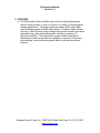
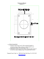
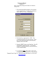
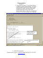
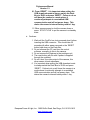
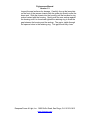
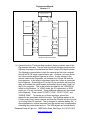
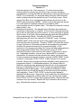
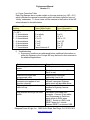
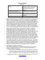
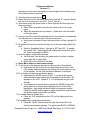
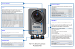
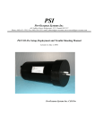
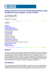
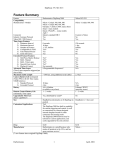
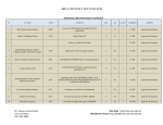
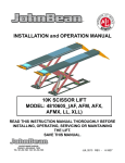
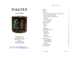
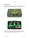
Digi-seacam Manual
Version 1.3
Digi-SeaCam
Owner’s Manual
Deepsea Power & Light, Inc. 3855 Ruffin Road, San Diego, CA. 92123-1813
www.deepsea.com
Digi-seacam Manual
Version 1.3
1) OVERVIEW
a) The Digi-seacam offers a flexible, high resolution digital photography
system which provides a ‘drop in’ solution to a variety of Oceanographic
imaging applications. The basic system provides a 4000 meter depth
rated (optional upgrade to 6000 meter rating), 3.3 Mpixel, digital camera
with up to 1GB of internal image storage and a corrected dome port which
generates crisp, wide angle photographs exhibiting a minimum of
geometric distortion. The camera can operate in either attended or
unattended modes and provides the capability to operate, change time
lapse settings, and upload photographs without opening the pressure
housing.
Deepsea Power & Light, Inc. 3855 Ruffin Road, San Diego, CA. 92123-1813
www.deepsea.com
Digi-seacam Manual
Version 1.3
2) SPECIFICATIONS
a) CAMERA
i) CAMERA SYSTEM: Nikon Coolpix 995
(1) Image sizes (user settable): 2048 X 1536 (FULL), 1600 X 1200
(UXGA), 1280 X 960 (SXGA), 1024 X 768 (XGA), 640 X 480 (VGA)
2048 X 1360 (3:2).
(2) Optical Zoom: 4:1
(3) Lens: Nikkor, f 2.8 – 5.1, 10 elements, 8 – 32 mm.
(4) Viewfinder: NTSC or PAL monitor video available on test video
output connector
(5) Storage, File System: Design rule for Camera File systems , Digital
Print-Order Format (DPOF) compliant.
(6) Storage, Compression: JPEG-based-compliant, FINE (~ ¼),
NORMAL (~1/8), BASIC (~1/16), HI (uncompressed: RGB – TIFF).
(7) Storage, Media: CompactFlash Card (Type 1 or Type 2)
(8) Sensitivity: ISO 100 equivalent (selectable Auto, ISO 100, 200,
400, 800)
(9) Shutter: 8 sec to 1/2000 sec
b) OPTICS
i) Port: 80mm diameter, hemispherical, tempered, BK-7 dome port.
ii) Corrective optics: Multi element, pseudo-telecentric corrector, A/R
coated.
iii) Field of View:
(1) Vertical: 46o
(2) Horizontal: 74o
c) ELECTRICAL
i) Power requirement: 10 – 34VDC, 1A max (nominal ~ .1A)
ii) Camera Control Port: EIA, RS-232 Compliant
iii) Camera Data (image upload) Port: USB compliant
iv) Strobe interface: xsync
v) Video output: Slow scan, 15 frames/sec, NTSC or PAL compliant
vi) Control: External switch closures may be used to: START, or STOP
time lapse, as well as snap a single photo.
d) MECHANICAL
i) Depth rating: 4000m standard, 6000m optional
ii) Pressure rating: 7000psi standard, 10,200psi optional
iii) Weight in air: 16.75 lbs (7.60 kg)
iv) Weight in water: 6.13 lbs (2.78kg)
v) Dimensions (L X W X H): 8” X 12.5” X 7”
vi) Materials: Aluminum Housing , MIL-A-8625F TYPE III, CLASS 1,
Dichromate seal anodize. Titanium end cap. Glass port.
Polypropylene crash guard, Acetal retainer.
vii) Installation Drawing: Rear view of mounting
bracket.
Deepsea Power & Light, Inc. 3855 Ruffin Road, San Diego, CA. 92123-1813
www.deepsea.com
Digi-seacam Manual
Version 1.3
e) OPERATING MODES
i) Attended: Camera may be set to take a single photograph on
command or begin taking a sequence of photographs at a preprogrammed interval until commanded to stop.
ii) Unattended: Camera may be set to delay a programmable interval of
time and then begin snapping images at a programmable interval.
Deepsea Power & Light, Inc. 3855 Ruffin Road, San Diego, CA. 92123-1813
www.deepsea.com
Digi-seacam Manual
Version 1.3
3) QUICK START (using Deck Box)
1. Quick start and checkout of the Digi-seacam
a. Getting started
i. Connections:
1. Connect Deck Box Cable 706-000-036 between the
Digi-seacam’s 5 pin connector and the Deck Box’s 8
pin connector.
2. Connect the Deck Box Cable 706-000-038 between
the Digi-seacam’s 16 pin connector and the Deck
Box’s 16 pin connector.
3. Connect the Host Serial Cable 706-000-040 between
the 4 pin connector on the Deck Box and the DB-9M
connector on the host computer.
4. DO NOT CONNECT the USB cable at this point.
5. Connect the Test Video Out jack on the Deck Box to
an appropriate monitor. Monitor should accept 1Vp-p
input video, 75 Ohm input impedance, RS-170A
signal standard.
6. Connect the strobe output jack to an xsync type
strobe trigger.
7. Connect the Deck Box Power Cable 706-000-039
between a standard 120VAC outlet and the Deck Box.
Press the ‘RESET’ switch on the GFCI, the green
LED on the Deck Box will glow. The camera may
wake up and immediately begin snapping pictures at
the programmed interval.
ii. Digisnap Configuration. The Digi-seacam remembers the
previous configuration data. On initial start up it is a good
Deepsea Power & Light, Inc. 3855 Ruffin Road, San Diego, CA. 92123-1813
www.deepsea.com
Digi-seacam Manual
Version 1.3
idea to verify these settings even if there is no desire to
change them.
1. Run a terminal emulation program on the computer
such as HyperTerminal. Configure the emulator for:
ANSI, 19200, 8-N-1 with no handshaking.
2. Set the deck box toggle switch to ‘LOAD’. This
connects the Digisnap to the host computer. When
set to ‘RUN’ (later in this script) it will connect the
Digisnap to the CoolPix 995.
3. Press the ‘RESET’ button on the Deck Box. The LED
will extinguish, release the button. If the terminal
emulator is configured correctly, a menu will scroll by
on the computer display.
4. To configure for either ‘Alvin’ mode or ‘sled’ mode,
set up the Simple Time Lapse mode. This is done by
Deepsea Power & Light, Inc. 3855 Ruffin Road, San Diego, CA. 92123-1813
www.deepsea.com
Digi-seacam Manual
Version 1.3
typing ‘M’ for set operating mode followed by return.
In the operating mode menu, select ‘T’ for simple time
lapse mode.
Select “m” from menu to
get configure the start up
mode.<enter>
Select “t” to start in Simple
Time Lapse mode when the
camera powers up.<enter>
Deepsea Power & Light, Inc. 3855 Ruffin Road, San Diego, CA. 92123-1813
www.deepsea.com
Digi-seacam Manual
Version 1.3
5. Exit that menu and select ‘T’ from the main menu to
configure the simple time lapse settings. You will be
guided through the setting up the number of images
to capture (0 for ‘infinite’), the time to delay before
starting the time lapse mode, and the interval
between image captures. Then exit to the main menu
and type ‘Q’ to quit (save changes, shut off Digisnap).
Select “t” again to
configure Simple Time
Lapse mode.<enter>
Input desired time increments.
<enter>
iii. CoolPix 995 Configuration
Deepsea Power & Light, Inc. 3855 Ruffin Road, San Diego, CA. 92123-1813
www.deepsea.com
Digi-seacam Manual
Version 1.3
1. The camera may have been turned off for shipment or
storage. To configure the camera, turn the camera on
M
for manual operation. (
see page 92 of the
Coolpix manual in Appendix A)
2. Disable the internal strobe by pressing the menu
button. ( Page 133 Nikon user’s manual-see appendix
A ).
a. Scroll down the menu and select the “S” tab.
This is called Set-Up1.
b. Using the camera button with the arrows, scroll
and select Speedlight Opt.
c. Select Int Flash off.
d. Select “yes” to enable the internal flash off
option. The external sync will still be active.
(The camera strobe must be unlatched for the
sync to fire).
e. Exit by pressing the menu button
3. Set manual focus. Hold down the manual focus button
(M-FOCUS on the rear of the camera) while adjusting
the focus setting with the rotary dial on the top. The
Digi-seacam focuses much closer underwater than
the focus numbers indicate, refer to the focus
correction table (see section 6 of this manual) to
accommodate this or set to ‘INF’ (INF is a good,
general purpose setting). (Page 81 Nikon user’s
manual)
4. Set the auto power down function to the shortest
interval (30 sec). ( Page 127 Nikon user’s manual).
a. In the Set-up 1 menu, select Auto Off.
b. Select 30s.
c. Exit by pressing the menu button
5. Set-up eternal strobe to trigger whenever a shot is
taken.
a. Press the Flash mode button repeatedly until
only the ‘lightning’ icon appears (the flash door
must be open/unlatched in order for this button
to function). (Page 69-70 in Nikon user’s
manual).
Deepsea Power & Light, Inc. 3855 Ruffin Road, San Diego, CA. 92123-1813
www.deepsea.com
Digi-seacam Manual
Version 1.3
b. Note that the camera internal camera strobe
must be unlatched for the sync to fire. As
factory configured, a bracket holds the flash
slightly open to facilitate this.
6. Set wide zoom as default mode.
a. In the Set-up1 menu, scroll and select Zoom
options.
b. Select Startup position.
c. Select wide.
d. Press the menu button to exit.
iv. Operating
1. Change the toggle switch on the Deck Box to ‘RUN’ to
connect the Digisnap to the CoolPix.
2. Press the ‘RESET’ button on the Deck Box. You
have just started the ‘Alvin’ mode and the camera will
begin snapping images at the preset interval – without
the programmed delay.
3. To stop the current cycle, press the ‘STOP CYCLE’
button on the Deck Box. Since the Digisnap woke up
the camera with the ‘take a picture’ command, at least
one photo will be snapped no matter how quickly you
press the ‘STOP CYCLE’ button. IF POWER IS
MOMENTARILY INTERRUPTED OR IF THE RESET
BUTTON IS PRESSED, THE CAMERA WILL REENTER ‘ALVIN’ MODE.
4. To capture a single image, press the ‘SINGLE SNAP’
button on the Deck Box. This will capture a single
image and then return the camera a Digisnap to
‘sleep’.
5. To start the ‘sled’ mode, press the ‘START CYCLE’
button on the Deck Box. The camera will snap 5
images at 15 second intervals (regardless of what the
programmed interval is), then it will start the
programmed delay period. At the conclusion of the
Deepsea Power & Light, Inc. 3855 Ruffin Road, San Diego, CA. 92123-1813
www.deepsea.com
Digi-seacam Manual
Version 1.3
programmed delay period, the camera will begin
acquiring images at the programmed interval.
6. To stop the camera either disconnect power or press
the ‘STOP CYCLE’ button. IF POWER IS
MOMENTARILY INTERRUPTED OR IF THE RESET
BUTTON IS PRESSED, THE CAMERA WILL REENTER ‘ALVIN’ MODE.
v. Uploading Images
1. Set the toggle switch on the Deck Box to ‘LOAD’
2. Disconnect power from the Deck Box (alternatively
hold down the ‘RESET’ button and wait for the
CoolPix 995 to power down (if a video monitor is
plugged into the video output jack, the display will go
black when the CoolPix powers down in 30 seconds).
3. Connect a the host computer to the Deck Box Cable
706-000-038’s USB breakout connector.
4. Reconnect power to the Deck/Launch Box (typically
only on or the other). Reconnecting power removes
the drain from the camera’s internal battery and
promotes battery life.
5. The ‘plug-n-play’ upload software should start and
upload the images from the camera. Save the
images to disk. (Nikon View 4 software is shipped
with the cameras for this purpose if a suitable
program is not available on the host).
6. When complete, delete the images from the Compact
Flash card using the host resident software to recover
memory in the camera.
7. Shut down the USB connection as appropriate for
your software.
8. Disconnect the Deck Box Cable 706-000-038 USB
connector from the Deck Box.
9. Set the Deck Box toggle switch to ‘RUN’
Deepsea Power & Light, Inc. 3855 Ruffin Road, San Diego, CA. 92123-1813
www.deepsea.com
Digi-seacam Manual
Version 1.3
10. Press ‘RESET’. It is important when exiting the
USB download mode to always switch the Deck
Box to ‘RUN’ and press ‘RESET’. Failure to do so
will leave the camera in a mode where it
continually attempts to re-establish USB
communication and will not power down. This
drains the camera’s internal battery within 1 day.
11. Either remove power to shut the camera down or
press ‘STOP CYCLE’ to put the camera in a standby
state.
vi. Cautions:
1. Wait until the CoolPix has ‘auto powered down’ before
inserting the USB connector. This should take 30
seconds with either power removed or the ‘RESET’
button held down on the Deck Box.
2. Do not reformat the CF card from the control
software, manually do this in the camera.
3. Do not remove the Digisnap in the prototype unit.
4. The reset button will not work if power is supplied
through the umbilical.
5. Do not ‘short’ the video output of the camera, this
driver seems to lack robustness.
6. It is important when exiting the USB download mode
to always switch the Deck Box to ‘RUN’ and press
‘RESET’. Failure to do so will leave the camera in a
mode where it continually attempts to re-establish
USB communication and will not power down. This
drains the camera’s internal battery within 1 day.
Deepsea Power & Light, Inc. 3855 Ruffin Road, San Diego, CA. 92123-1813
www.deepsea.com
Digi-seacam Manual
Version 1.3
4) MECHANICAL
a) GENERAL: The Digi-seacam is designed to resist normal exposure to the
ocean environment with a minimum of maintance. Rinsing the camera
with fresh water will not only help minimize corrosion of the housing but
will minimize salt encrustation on the dome port. The main housing is
anodized aluminum which is electrically isolated from the camera
assembly. The housing is electrically connected to the stainless steel
mounting bracket which allows the zinc corrosion inhibitors to be attached
to the mounting bracket. Periodically, the protective zinc anodes should
be checked and replaced when they are depleted. The housing end cap
is titanium and should be extremely resistant to corrosion. The glass
dome view port should be cleaned with a soft cloth to avoid scratching.
The curvature of this dome is part of the lens system so avoid damaging
the surface.
i) DIMENSIONS AND MOUNTING REQUIREMENTS: The outline and
installation dimensions for the Digi-seacam can be found on drawing #
735-001-001 which is attached. The Digi-seacam weighs 16.75 lbs
(7.60 kg) in air, 6.13 lbs (2.78kg) in water. The main umbilical
connector is available in either a right angle or a straight exit to
facilitate mounting.
ii) EXPLODED VIEWS: Exploded views are provided for both the rear
end cap (735-001-018) and the dome assembly (735-001-022).
Disassembly of the dome is strongly discouraged. If at all possible,
this should be returned to Deepsea for service.
iii) O-RING SERVICE: The rear end cap will periodically need to have the
o-rings replaced. Every time the camera is opened, the o-rings should
be checked for nicks and wear. Lubricate and clean o-rings with a
good quality grease such as Dow Corning DC-111 silicone grease.
The exploded views of the assemblies above show the location and
size of o-rings in the Digi-seacam. The connectors also contain orings. The connector manufacturer’s drawings are attached to
reference the location and replacement of connector o-rings.
iv) OPENING THE HOUSING: Prior to opening the housing, it is always
recommended to flush (with fresh water) out the area around the
endcap to loosen salt and debris which may accumulate there.
Following flushing, blow the remaining water away with compressed
air. With the connector cover plate in place (item #9 in 735-001-018),
unscrew the rear retaining ring (item # 3 in 735-001-018) using either a
strap wrench or a spanner wrench. The retaining ring will drive the
connector cover plate backwards, removing the camera from the
housing.
v) CLOSING THE HOUSING: Ensure that the threads on the housing and
retaining ring are clean, a light coat of silicone grease on the threads
may ease re-assembly. Prior to re-assembly, recharge the dessicant
pack if the camera has been open for an extended period of time.
Deepsea Power & Light, Inc. 3855 Ruffin Road, San Diego, CA. 92123-1813
www.deepsea.com
Digi-seacam Manual
Version 1.3
Inspect the seal surfaces for damage. Carefully line up the lens plate
on the front of the camera chassis with the guide slot directly under the
dome port. Slide the chassis into the housing until the boreseal o-ring
makes contact with the housing. Gently push the rear endcap against
the housing until it is closed and tighten the retaining ring to close the
gap between the housing and the endcap. The gap is visible through
the spanner holes in the retaining ring. This gap should fully close.
Deepsea Power & Light, Inc. 3855 Ruffin Road, San Diego, CA. 92123-1813
www.deepsea.com
Digi-seacam Manual
Version 1.3
5) ELECTRICAL
a) Camera interface: There are two connectors on the rear end cap of the
Digi-seacam which provide the electrical interface to the outside controls
and power. Power can be supplied through either connector to maximize
the flexibility of operation. If either connector is not used during a dive, it
must have the mating ‘dummy plug’ inserted. The 16 pin main connector
is intended to be the primary interface to either a host computer or a
vehicle. The 5 pin auxiliary connector provides uninterrupted power to the
camera when transitioning from the Deck Box to the vehicle’s umbilical
cable. Internal diodes within the camera prevent one external power
source from driving another.
i) Connector pinout: The interface connector pinouts are shown below:
IMPULSE
MHDL-16-FCR
BULKHEAD
CONNECTOR
1
COMMON (USB/RS-232/VIDEO)
2
PWR (9-36VDC)
3
VIDEO
4
GND (PWR)
5
RS232 TRANSMIT/STEREO
6
RS232 RECEIVE
7
USB D+
8
USB +5V
9
USB D-
10
RELAY
11
STOP CYCLE
12
RESERVED
13
RESERVED
14
RESERVED
15
STROBE - GROUND
16
STROBE-TRIGGER
1
IMPULSE
LPBH5FS
BULKHEAD
CONNECTOR
2
3
4
5
GND
PWR
VIDEO
START CYCLE
SINGLE SNAP
DIGI-SEACAM REAR CONNECTOR PIN OUT
Power is supplied to the camera on pin 2 of either connector. Input power is 934VDC, 1 amp peak. Video is available from the camera on pin 3 of both
connectors any time that the camera is in picture taking mode. This provides a
viewfinder for aiming the camera prior to snapping a photograph. Data
overlayed on the video allows the to verify many of the camera settings.
Deepsea Power & Light, Inc. 3855 Ruffin Road, San Diego, CA. 92123-1813
www.deepsea.com
Digi-seacam Manual
Version 1.3
8.25VDC
9-36VDC
CAMERA POWER SUPPLY
SWITCH
SIGNALS
DIGISNAP 2300
9-36VDC
5VDC
SWITCH
SIGNALS
SERIAL
CONTROL
8.25V
INTERFACE PCB
SERIAL
CONTROL
COOLPIX 995
DIGISEACAM BULKHEAD
SERIAL
CONTROL
VIDEO
USB
USB
STROBE
STROBE
DIGISEACAM BLOCK DIAGRAM
b) Camera function: The block diagram above shows a system view of the
Digi-seacam internally. The two main functional elements inside are the
Digisnap time lapse controller and the Nikon Coolpix 995 digital camera.
The Digisnap communicates to both the camera and the host computer
through a RS-232 serial communication port. However, only one device
can communicate with the Digisnap at a time. A relay internal to the
camera switches the Digisnap’s port between the Coolpix 995 and the
host computer. In the relay’s unpowered state, the Coolpix is connected
to the Digisnap. Grounding pin 10 on the 16 pin connector will close the
relay and connect the serial receive and transmit lines to pins 6 and 5 of
the 16 pin connector. This is the function provided by the ‘LOAD/RUN’
switch on the Deckbox. In ‘LOAD’ mode; pin 10 is grounded, in ‘RUN’
mode; pin 10 is not connected. Three additional switches are connected
to the Digisnap. These control ‘START CYCLE’, ‘STOP CYCLE’, and
‘SINGLE SNAP’. To actuate any of these functions, ground the
respective pin associated with the function. The Digisnap wakes up the
Coolpix every time it takes a picture and then the Coolpix will time out and
‘go to sleep’ after 30 seconds. This is designed to optimize battery life. In
some applications, quicker response from the camera may be obtained by
extending the power down time out. The USB signals are routed directly
Deepsea Power & Light, Inc. 3855 Ruffin Road, San Diego, CA. 92123-1813
www.deepsea.com
Digi-seacam Manual
Version 1.3
from the camera to the 16 pin connector. To avoid communication
conflicts within the camera, pin 10 of the 16 pin connector should be
grounded when running the USB link (alternatively, switch the Deck Box to
‘LOAD’ if it is connected). It is important when exiting the USB download
mode to always remove the ground from pin 10 and cycle power. When
using a Deck Box this is accomplished by switching the function to the
‘RUN’ mode and pressing ‘RESET’. Failure to do so will leave the camera
in a mode where it continually attempts to re-establish USB
communication and will not power down. This drains the camera’s internal
battery within 1 day.
c) Operational Connection: The diagram below illustrates the operational
connection of the camera to a vehicle. Prior to launch, Digisnap would be
set up with its initial delay and photo interval. As soon as power is applied
to the camera, it will ignore the programmed delay and start taking photos
at the programmed interval. Actuating the ‘STOP’ command after
applying power will return the camera to ‘STAND BY’ mode. Pressing
‘SINGLE SNAP’ at this point will result in the camera taking one photo
each time the button is pressed. Pressing ‘START’ will cause the camera
to snap 5 pictures at 15 second intervals to acknowledge the command
and then the camera will execute the programmed delay. At the
conclusion of the programmed delay, the camera will begin taking pictures
at the programmed interval until: a) the camera is given a ‘STOP’
command, b) power is removed from the camera, c) the memory card is
full. In attended operation, such as from a tethered ROV or manned
submersible, the camera could be actuated from either: turning on power
to start a programmed interval of photos, pressing ‘SINGLE SNAP’ to take
one photo, or pressing ‘START CYCLE’ to take 5 photos at 15 second
intervals, followed by a programmed delay, followed by taking photos at a
programmed interval. In unattended operation, the camera could be
started by supplying power and having it take pictures at a programmed
interval or by actuating ‘START CYCLE’ to begin a programmed delay
followed by interval photography. One scenario for operating in ‘delay’
mode would be to connect the camera to the Deck box prior to launch to
verify operation. Press ‘STOP CYCLE’ to stop the cycle started by
applying Deck Box power. Remove the 16 pin cable from the Deck Box to
the camera. Connect the umbilical cable from the vehicle power supply.
Press ‘START CYCLE’ to begin the programmed delay. Remove the 5 pin
connector from the camera. Replace the 5 pin connector with a dummy
plug. Reinstall the connector cover plate.
Deepsea Power & Light, Inc. 3855 Ruffin Road, San Diego, CA. 92123-1813
www.deepsea.com
Digi-seacam Manual
Version 1.3
GND (PWR)
706-000-032 CABLE
5 USED
M
H
D
L
1
6
F
C
R
M
H
D
L
1
6
C
C
P
PWR
ALVIN
CABLE
RS232 TRANSMIT/STEREO
STROBE-GROUND
STROBE-TRIGGER
BOTH CABLES SHOWN, ONLY
ONE IS USED AT A TIME
5 USED
SLED
CABLE
REMOVE PRIOR TO LAUNCH
120V
PWR
Digiseacam
M
H
D
L
1
6
C
C
P
4
2
5
15
GND (PWR)
PWR
RS232 TRANSMIT/STEREO
STROBE-GROUND
16 STROBE-TRIGGER
RMG-3-FS
XSG-3-BCL
L
P
B
H
5
F
S
L
P
I
L
5
M
P
XSL16BCR
(W)
5
DECK BOX
XSL8CCP
(W)
XSL8BCR
(W)
TEST
VIDEO
REPLACE WITH DUMMY PLUG
BEFORE IMMERSION
TO DECK
MONITOR
DIGISEACAM OPERATIONAL CONFIGURATION
BLOCK DIAGRAM
Deepsea Power & Light, Inc. 3855 Ruffin Road, San Diego, CA. 92123-1813
www.deepsea.com
Digi-seacam Manual
Version 1.3
M
H
D
L
1
6
F
C
R
M
H
D
L
1
6
C
C
P
16
USB
120V
PWR
Digiseacam
TO HOST COMPUTER
RMG-3-FS
XSG-3-BCL
XSL16CCP
(W)
L L
P P
B I
H L
- 5 5
- F M
S P
XSL16BCR
(W)
DECK BOX
5
XSL8CCP
(W)
XSL8BCR
(W)
TEST
VIDEO
TEST
SYNC
TO DECK
MONITOR
TO TEST
STROBE
X
S
G
4
B
C
L
R
M
G
4
F
S
SERIAL
DIGISEACAM TEST & CHECKOUT CONFIGURATION
BLOCK DIAGRAM
Deepsea Power & Light, Inc. 3855 Ruffin Road, San Diego, CA. 92123-1813
www.deepsea.com
Digi-seacam Manual
Version 1.3
6) OPERATION: The bulk of the operating instructions are covered in the
Digisnap and 995 manuals attached in Appendix A and B. While many of the
995 parameters can be set through the Digisnap, there are some important
functions which can only be set manually (focus in particular). To operate
properly, the 995 must be set to ‘Manual’ mode and left ‘on’. The camera
focus must be set manually. A setting of ‘INF’ (infinity) will provide a crisp
focus as f2.8 from 1 meter to infinity. It is also important to leave the flash on
the Coolpix 995 ajar as the flash contacts will not actuate if the flash door is
closed. A bracket on the internal chassis assembly holds the flash door in the
correct position and should not be removed. The flash should be set to fire
without using the camera’s internal flash. Firing the internal flash in the
housing will likely result in undesirable glare in the photo.
a) SUGGESTED DEFAULT CAMERA SETTINGS: Setting up the camera
must be performed with the camera removed from the pressure housing.
These settings are covered in greater detail in the either the Coolpix 995
manual or the quick start guide. Depending on the application any or all of
these may need to be modified. The Coolpix 995 manual is included as
appendix A of this document.
i) Manual Mode
M
(see page 44 of Coolpix 995 manual)
(1) Set the Mode Dial to
(2) Select Manual Exposure Mode (see page 65 of Coolpix 995
manual)
(3) Select a shutter speed of 1/60th and an aperature of f:2.6 (see page
65 of Coolpix 995 manual)
ii) Internal strobe disabled (see page 133 of Coolpix 995 manual)
iii) Manual Focus set to distance indicated on rear endcap of camera
pressure housing (see page 81 of Coolpix 995 manual)
iv) Auto Power Off set to 30 sec (see page 127 of Coolpix 995 manual)
v) External strobe enabled (see page 69 of Coolpix 995 manual)
vi) Zoom wide Start-up position (see page 132 of Coolpix 995 manual).
vii) Resolution: Fine, Full (no indication – 1.6MB/photo) Setting resolution
to HI will result in uncompressed photos stored in .tif files which will
require ~ 10MB/photo(see page 58 of Coolpix 995 manual)
viii)Saturation: 0 (for color) or B&W (for monochrome) (see page 105 of
Coolpix 995 manual)
b) SUGGESTED DIGISNAP SETTINGS: These settings are performed over
the serial link from the host computer. All of these may be set with the
pressure housing closed. The complete Digisnap manual is attached to
this document at appendix B.
i) Simple time lapse mode (see page 10 of Digisnap manual)
ii) Switch menu (see page 16 of Digisnap manual)
(1) Switch 1: zoom out
(2) Switch 2: start STL
(3) Switch 3: stop STL
Deepsea Power & Light, Inc. 3855 Ruffin Road, San Diego, CA. 92123-1813
www.deepsea.com
Digi-seacam Manual
Version 1.3
(4) Switch 4: zoom in
(5) External Switch: snap 1
c) Operating Power: When operating the camera must be supplied with 9 –
34 VDC power.
d) Operating Modes: The camera may be operated in one of three modes.
i) Attended operation: In this mode, an operator has access to the
camera control signals for ‘Start Cycle’, ‘Stop Cycle’, and ‘Single
Snap’.
Deepsea Power & Light, Inc. 3855 Ruffin Road, San Diego, CA. 92123-1813
www.deepsea.com
Digi-seacam Manual
Version 1.3
e) Focus Correction Table
Each Digi-Seacam has a number written on the rear endcap (e.g. INF = 2.8’)
which indicates the camera focus setting which will obtain optimum focus at
‘infinity’ underwater. To focus closer, set the camera to the fraction of the INF
value indicated in the table below.
995 Manual Focus
Setting
Value on rear endcap
(F = INF)
F – 1 focus detents
F – 2 focus detents
F – 3 focus detents
F – 4 focus detents
F – 5 focus detents
F – 6 focus detents
F – 7 focus detents
Corrected Underwater
Focus (Wide Angle)
4’ to infinity
Corrected Underwater
Focus (Zoomed In)
10’ to infinity
2’ to infinity
1’ to 15’
.5’ to 10’
.3’ to 8’
.2’ to 6’
.1’ to 4’
Face of dome to 2’
3’ to 10’
1.5’ to 3’
1.25’ to 1.5’
1’ to 1.25’
9” to 12”
8” to 10”
7” to 8”
f) Troubleshooting
i) Some error conditions are addressed below, additional information on
either the Digisnap or the Coolpix 995 may be found in their manuals in
the attached appenidices.
Problem
Camera appears to not have
power
Interval time longer than
programmed value
Deck Box buttons (or respective
connector pins appear to not
function correctly)
Digisnap locks up, reset does not
clear lock up.
Digi-seacam will not go into USB
mode
Suggestions
Check power connections
Check fuse in camera (and Deck
Box if in use)
Reduce photo resolution,
particularly if set to HI
Digisnap defaults have been
restored, reprogram Digisnap
switch menu as described above.
Check to see if battery was
installed in Digisnap, remove
battery.
Disconnect USB cable from
computer. Connect 16 pin cable
from Digi-seacam to Deck box,
switch mode to RUN, press
RESET. Switch to LOAD, hold
RESET down for 1 minute.
Release RESET, re-connect USB.
Deepsea Power & Light, Inc. 3855 Ruffin Road, San Diego, CA. 92123-1813
www.deepsea.com
Digi-seacam Manual
Version 1.3
Digi-seacam will not leave USB
mode
Terminal Emulator will not
communicate with Digi-seacam
Disconnect USB cable from
computer. Connect 16 pin cable
from Digi-seacam to Deck box,
switch mode to RUN, press
RESET.
Check settings: 19.2kBaud, N-8-1
Try inserting a ‘null modem’
between the serial cable and the
computer
Loss of time/date/presets: The Coolpix 995 has an internal secondary battery in
addition to the primary battery which is not removable but is rechargeable in the
camera. This secondary battery’s function is to maintain the presets stored in
memory and keep time. This secondary battery is charged by either application
of external power or by the camera’s main battery. In the absence of either, this
battery will slowly discharge over a period of time varying from hours to weeks.
Loss of time/date/presets is indicated by the clock icon flashing on the output
video (or the 995’s LCD). See 995 manual page 17, Monitor (in shooting mode)
icon #5. This problem can be resolved in one of three ways: 1) leave a charged,
primary battery in the 995 when it is stored for short periods, 2) leave the
Digiseacam connected to external power when it is stored, 3) connect the
auxiliary battery pack to the camera when it is stored. The three ‘AA’ cell
auxiliary battery pack will maintain time/date/presets for approximately 6 months.
To install the auxiliary battery pack, open the pressure housing. Mount the
auxiliary battery pack to the black, acetal guide disk at the end of the camera
chassis. Route the two pendant cables from the auxiliary battery pack through
the inside of the guide disk to the front of the camera. To connect the auxiliary
battery pack, unplug the external power plug from the front of the 995, reconnect
this plug into the mating jack of the auxiliary battery pack. Connect the auxiliary
battery packs power plug to the external power jack on the front of the 995.
Insert three fresh, alkaline ‘AA’ cells into the auxiliary battery pack. This battery
pack will not operate the camera but it will maintain the secondary battery in the
camera. When external power is applied to the Digiseacam, the auxiliary battery
pack will automatically switch over to this source. This battery pack does not
charge from external power and should be replaced when it is depleted.
Resetting time and date and presets:
This must be done directly on the camera and requires opening the pressure
housing. Operating the camera will require connecting external power or
inserting a battery into the camera.
1) The first step is to recharge the internal secondary battery in the camera.
This requires either inserting a fresh primary battery or applying external
power. It takes about 8 hours to fully charge the secondary battery. The
Deepsea Power & Light, Inc. 3855 Ruffin Road, San Diego, CA. 92123-1813
www.deepsea.com
Digi-seacam Manual
Version 1.3
time can be reset before this battery is fully charged but the settings may
be lost when power is removed.
M
2) Turn the camera mode dial to
.
3) Press the menu button and scroll down to the last tab “S” using the button
with the four arrows next to the LCD. This is ‘Set-Up 1’
4) Scroll down using the arrow button to Zoom Options and then right click
the arrow button.
a. Select Start Up position and click the arrow button to the right
again.
b. Select the desired start up positions…(Wide) then click the button
to the right again.
5) Scroll to Auto Off to select the desired time for the camera to automatically
turn off when not in use and right click the arrow button.
a. Use the arrow button to select the desired shut off time, typically 20
sec.
6) Scroll past the last item and this will take you to the next page called ‘SetUp 2’.
a. Scroll to Speedlight Option. Now go to INT Flash Off. To enable
this, select “ON”. Selecting ON will enable the internal flash to be
off (Nikon’s equivalent of RPN).
7) Scroll to Date to set the date and time.
a. Set Date and Time by using the arrow button (up-down to adjust
value/ right-left to select field).
b. Right click in the last field to set date
8) Press Menu button to save menu settings
9) To set focus to the distance indicated on the end cap of the camera:
a. Hold down the M-Focus button located below the left side of the
LDC display while simultaneously rotating the thumb wheel on top
of the camera. Do this until the desired distance is achieved.
10) To manually set aperture and shutter speed.
a. Hold down the ‘MODE” button (FUNC. 1) on top of the camera
while simultaneously rotating the thumb wheel until the letter “M”
appears on the LCD. Letters S, P, or A will appear as you scroll
through.
b. To set aperture & shutter speed, release the ‘MODE’ button and
either aperture or shutter speed displayed on the LCD will be
highlighted. Just rotate the thumb wheel to change the setting.
Press the ‘MODE’ button again to toggle between the aperture and
the shutter speed so the other can be set.
11) To enable External Strobe Sync:
a. Press the ‘ISO’ button below the LCD until the lighting bolt icon
appears.
12) Changing image compression/resolution:
a. Press the “QUAL” button below the right side of the LCD until
desired compression appears. The options are BASIC, NORMAL,
Deepsea Power & Light, Inc. 3855 Ruffin Road, San Diego, CA. 92123-1813
www.deepsea.com
Digi-seacam Manual
Version 1.3
FINE, and HI. HI employs no image compression but requires
approximately 10MB per image. The estimated number of images
the camera will store in memory are displayed below the
compression option.
b. Hold down the “QUAL” button while rotating the thumbwheel to
obtain the image resolution. No resolution displayed is the full
imager’s resolution (3.3Mpixel).
Deepsea Power & Light, Inc. 3855 Ruffin Road, San Diego, CA. 92123-1813
www.deepsea.com
Digi-seacam Manual
Version 1.3
7) SPARES & MAINTENANCE: The Digi-seacam is designed to provide a long
service life with a minimum of maintenance. Ideally after every dive, the
camera should be rinsed with fresh water and the dome port dried with a soft
cloth to minimize water spots on the dome. This will also minimize corrosion
of the housing. When ever the camera is opened, the o-rings should be
checked for nicks and wear to prevent leaks. The camera battery will
occasionally need to be either charged or replaced, this requires opening the
housing. If the camera battery is dead, it may display a message indicating
that it does not have sufficient time to store the image on the output video.
This will appear in spite of the fact that external power is connected to the
camera. The dead battery must be removed and either left out or replaced
with a fresh battery to continue operation. Battery life can be maximized by
always shutting the camera down in ‘RUN’ mode. The camera may be
operated without a battery, however unless the camera is used every few
days, it may ‘forget’ it’s manual setup and require the user to reset these.
Applying power to the camera every few days will prevent even a camera
without a battery from losing its settings.
a) Spares List:
REC. QTY. DSPL PART #
DESCRIPTION
1
2-157 N0674-70
O-RING
1
2-242 N0674-70
O-RING
1
2-234 N0674-70
O-RING
1
2-235 N0674-70
O-RING
1
2-245 N0674-70
O-RING
1
530-00059
BACK UP RING
1
5x20mm 3.15A FUSE
DIGI-SEACAM INTERNAL
1
3AG 1A FAST BLOW FUSE DECK BOX INTERNAL
1
140-00241
LPDG-5-MP DUMMY PLUG
b) Camera Replacement: In the unlikely event that the Coolpix 995 should
need to be replaced, it is relatively easy to remove the unit mounted into
the Digiseacam and replace it with another unit. The camera itself has
requires no modification except perhaps the removal of the nub on the
mode knob. To remove the existing camera:
i) Remove the camera chassis from the housing
ii) Disconnect the external power input to the front of the camera.
iii) Remove the battery pack mounting plate from the centralizer assembly
iv) Disconnect the video connector from the right side of the camera (as
viewed from the back)
v) Disconnect the USB/RS232 port connector from the right side of the
camera (as viewed from the back).
vi) Remove the screws securing the strobe retainer to the top of the
camera (screws fasten to the lens mount), and remove the strobe
retainer.
vii) While holding the camera to the chassis with one hand, remove the ¼20 socket head cap screw that retains the camera to the chassis.
Deepsea Power & Light, Inc. 3855 Ruffin Road, San Diego, CA. 92123-1813
www.deepsea.com
Digi-seacam Manual
Version 1.3
viii)Separate the camera from the chassis by about ½ inch. Carefully
unscrew the strobe sync cable from the underside of the lens
assembly.
ix) Lift the camera free of the chassis.
x) Carefully unscrew the diopter retaining ring from the front of the
camera lens.
xi) Carefully remove the diopter.
xii) Eject the CF card from the camera
c) Installation of new camera:
i) Place a CF card in the new camera
ii) Carefully position the diopter, convex side out over the new camera
lens.
iii) Carefully screw in the diopter retaining ring to secure the diopter to the
camera.
iv) Carefully mate and secure the strobe sync connector to the camera.
v) Locate the lens into the lens aligning bracket and secure the camera
body in place with the ¼-20 retaining screw.
vi) Release the strobe door.
vii) Align the strobe retaining bracket over the strobe so that the strobe
does not completely close.
viii)Secure the strobe retaining bracket with the screws provided.
ix) Connect the USB/RS-232 connector, paying attention to the polarity
keys on the connector.
x) Connect the video cable
xi) Connect the external power connector to the camera.
xii) Secure the battery pack in place.
xiii)Examine the camera for loose screws and insure that all cables are
routed to prevent them from snagging on any edges.
xiv) Reinsert the camera into the housing, purge, and seal.
8) APPENDIX
a) APPENDIX A: COOLPIX 995 MANUAL
b) APPENDIX B: DIGISNAP 2300 MANUAL
c) APPENDIX C: DIGI-SEACAM DRAWINGS
d) APPENDIX D: DECKBOX
Deepsea Power & Light, Inc. 3855 Ruffin Road, San Diego, CA. 92123-1813
www.deepsea.com