1
1/29
Optimus äänitasomittari
Käyttöohje
Markkinointi:
Pietiko Oy
www.pietiko.fi
2/29
Sisällysluettelo
Johdanto.....................................................................................................................................................3
Voice Tag äänen tallennus.....................................................................................................................4
Yksi mittausalue....................................................................................................................................4
Selkeä, yksinkertainen näyttö................................................................................................................4
Modulaarinen rakenne ..........................................................................................................................4
Optimus äänitasomittarin esittely...............................................................................................................5
Optimus edestä......................................................................................................................................5
Optimus sivulta ja takaa........................................................................................................................6
Näyttö....................................................................................................................................................7
Painikkeet..............................................................................................................................................7
Pikaohjeet...................................................................................................................................................8
Äänitason mittaus..................................................................................................................................8
Leq mittaus ...........................................................................................................................................8
Käytön aloitus........................................................................................................................................9
Mikrofonin ja esivahvistimen kytkentä......................................................................................................9
33/33......................................................................................................................................................1
Esivahvistimen poisto..........................................................................................................................12
Mikrofonin jatkokaapelin käyttö ........................................................................................................12
Paristojen asennus...............................................................................................................................12
Paristojännitteen näyttö.......................................................................................................................12
Ulkoinen virransyöttö..........................................................................................................................13
Ensiasetukset............................................................................................................................................13
Aika ja päivämäärä esitys....................................................................................................................13
Kielen valinta......................................................................................................................................13
Muistiin tallennuksen taajuus..............................................................................................................13
Aikapainotus........................................................................................................................................14
Integrointiasetukset.............................................................................................................................14
Äänitasonäytön väri ............................................................................................................................14
Muistin tyhjennys................................................................................................................................14
Voice Tag.............................................................................................................................................14
Mittaaminen.............................................................................................................................................15
Käynnistys...........................................................................................................................................15
Mittarin kalibrointi..............................................................................................................................15
Tuulisuojan käyttö ..............................................................................................................................16
Mittauksen aloitus...............................................................................................................................16
VoiceTag äänikommentti.....................................................................................................................16
Mittaustuloksen katselu.......................................................................................................................16
Esimerkkejä näytöistä..........................................................................................................................17
Mittauksen uudelleen aloitus...............................................................................................................17
Mittauksen pysäytys............................................................................................................................17
Tulosten tallennus ...............................................................................................................................17
Mittaustulosten tarkastelu....................................................................................................................17
Tulosten lukeminen mittarin muistista................................................................................................18
Läitteen poiskytkentä..........................................................................................................................18
3/29
Moduulit...................................................................................................................................................19
Moduulien toiminnot................................................................................................................................19
General View.......................................................................................................................................19
Sound level View.................................................................................................................................20
Leq View.............................................................................................................................................20
Oktaavikaistat......................................................................................................................................20
Dose View...........................................................................................................................................21
Mittarin asetukset.....................................................................................................................................22
Aikapainotus........................................................................................................................................22
Pika-asetukset......................................................................................................................................22
Kellon asetus.......................................................................................................................................23
Voice Tag.............................................................................................................................................23
Äänitason värit. (Colors).....................................................................................................................23
Kielen valinta (Language)...................................................................................................................23
Muisti (Storage)..................................................................................................................................23
Time History data Rate........................................................................................................................23
Näytön kirkkaus (Screen Brightness)..................................................................................................23
Screen Saver ( Näytön säästäjä)..........................................................................................................24
Set Date@ Time Formats (Ajan esitysmuoto).....................................................................................24
Restore Factory settings (Palauta tehdasasetukset )............................................................................24
Projected Exposure Calculation..........................................................................................................24
How is Lep,d calculated?....................................................................................................................25
Mittausten tallentaminen Noise Tools ohjelmalla....................................................................................26
Noise Tools ohjelmiston asennus........................................................................................................26
Ohjelmiston käyttö .............................................................................................................................26
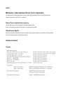
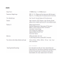
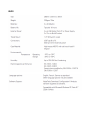
Tekniset tiedot..........................................................................................................................................26
Yleiset............................................................................................................26
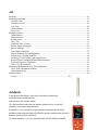
Johdanto
Cirrus Reaserchin Optimus sarja tekee mittausten suorittamisen
mahdollisimman yksinkertaiseksi:
Mittaa kaiken eikä unohda mitään!
Yksi tärkeimmistä omnoisuuksista optimus mittareissa on, että kaikki
mittaukset suoritetaan samanaikaisesti.
Esimerkiksi, jos olet mitannut sarjan mittauksia nopealla aikavakiolla ja
haluatkin saada tulokset hitaalla aikavakiolla, muuta yksnkertaisesti aikavakio
hitaaksi ja katso tuloksia uudelleen.
Jos mittari näyttää Leq- arvoja, mutta haluatkin TWA:n OSHA standardin
4/29
mukaan, älä huolehdi, mittarissa on muistissa myös nämä lukemat.
Voice Tag äänen tallennus
Tiedon keruu ominaisuudella varustetu Optimus mittarit sisältävät VoiceTag äänentallennus
ominaisuuden. Voit tallentaa kommentteja ja tietoa mittauksesta ennen mittausta puhumalla
yksinkertaisesti mikrofoniin.
Tallentamalla kommentit puhumalla mittariin, sinun ei tarvitse kantaa mukanasi kynää ja paperia vaan
voit tallentaa kaiken informaation mittariin
Yksi mittausalue
Optimussa käytetty digitaalitekniikka yhdistettynä 30 vuoden kokemukseen äänitasomittareiden
suunnittelussa mahdollistaa Optimus mittareiden mitta-alueeksi 20dB(A) ..140 dB(A) ja 143 dB(A)
peak. Yhtenä ainoana mitta-alueena!
Sinun ei siis tarvitse päättää mitä mitta-aluetta käytät ja mahdollisuus alueen ylitykseen tai alitukseen
on hyvin pieni.
Selkeä, yksinkertainen näyttö
Optimuksen näyttö on suuren tarkkuuden omaava väri OLED näyttö, joka näkyy hyvin kaikissa
valaistuksissa ja mahdollistaa värien käytön informaation jaotteluun.
Tarvittava mittaustulos näkyy selkeästi näytöllä siten, että tärkein tulos näytetään suurilla numeroilla.
Modulaarinen rakenne
Optimus mittariperha on suunniteltu modulaariseksi siten, että mittari voidaan päivittää ja siihen
voidaan helposti asentaa uusia ominisuuksia. Voit siis lisätä mittariin ominaisuuksia kun
mittaustarpeesi lisääntyvät.
5/29
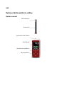
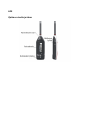
Optimus äänitasomittarin esittely
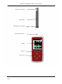
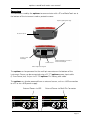
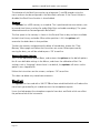
Optimus edestä
Mirofonikapseli
Esivahvistin
Ympäristön valon ilmaisin
OLED näyttö
Ohjelmoitavat painikkeet
Ohjauspainikkeet
6/29
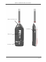
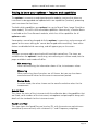
Optimus sivulta ja takaa
7/29
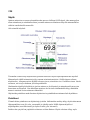
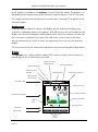
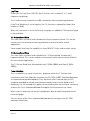
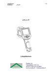
Näyttö
Optimus mittareissa on suuren piirtotarkkuuden omaava värillinen OLED näyttö, joka antaaa paljon
tietoa mittauksesta ja mittalaitteen tilasta ja samalla mittaussovellutukseen liittyvän mittaustuloksen
selkeästi suurikokoisilla numeroilla.
Alla esimerkki näytöstä:
Tietonauha sisältää tietoja näytön tilasta, pariston tilasta sekä ohjeen ohjausnpainikkeiden käytöstä
Mittausnäyttö sisältää mittaustietoja joko suoraan tai mittarin muistista. Sisältö riippuu valitusta
näyttötavasta. Alimpana on tieto näytöllä olevasta sivusta, esimerkissa sivu 1 kolmesta sivusta. Nuolet
osoittavat, että sivuja vaihdetaan ylös/alas painikkeilla.
Olotilanauha näyttää päivämäärän ja ajan kun mittaus eo ple käynnissä ja mittaukseen käytetyn ajan
kun mittaus on käynnissä. Kun katsellaan muistissa olevaa tietoa olotilanauhalla näkyy mittauksen
numero/ muistissa olevien mittausten lukumäärä
Ohjelmoidut painikkeet nauha ilmoittaa ohjelmoitavien painikkeiden toiminnot tässä näyttötilassa.
Painikkeet
Ylimmät kolme painiketta ovat ohjelmoituja ja niiden kulloinenkin merkitys näkyy näytön alareunassa
Ohjauspainikkeet ovat ylös, alas, vasemmalle ja oikealle nuolet. Näillä ohjataan näyttöä eri
näyttötapoihin (vasen/oikea nuoli) ja näytön sivuille (ylös/ alas nuoli)
Painikevalot syttyvät kun ympäristön valon taso on liian alhainen. Näytön valoisuus säätyy myös
8/29
valaistuksien mukaan.
Pikaohjeet
Äänitason mittaus
Käytettävissä kaikissa malleissa
1. Kytke mittari päälle
2. Tarkista kellonaika
3. Valitse äänentasonäyttö : Sound Level Mittari näyttää äänentason (LAF)
4. Tarkista aikapainotus . Muuta jos tarvitaan
5. Kalibroi mittari : Aseta kalibrattori mikrofonin päälle ja paina Calibrate painiketta
6. Käynnistä mittaus : Paina Start
7. Käynnistä ääniviesti: Voit tallentaa puhetta painamalla record painiketta. Tämä toiminto on
ainoastaan tiedon keruulla(datalogger) varustetuissa mittareissa
8. Tarkastele mittaustuloksia: Kun mittaus on käynnissä tietonauhan vasemmassa kulmassa oleva
ilmaisin pyörii. Käytä ylös/alas nuolia siirtyäksesi näytön eri sivuille
9. Pysäytä mittaus: Paina Stop painiketta. Mikäli datalogger on asennettu, tulos tallentuu
automaattisesti muistiin.
10. Tarkastele mittaustuloksia: Mittaustulokset näkyvät edelleen näytöllä
11. Paina Exit lopettaaksesi
Leq mittaus
Saatavissa Optimus Red (160- sarjan) mittareissa
1. Kytke mittari päälle
2. Tarkista kellonaika
3. Valitse Leq näyttö : käytä vasen/oikea nuolia. Mittari alkaa näyttää 1 sekunnin Laeq ja kaavissa
kertyneitä tuloksia.
4. Tarkista asetukset . Paina Menu ja valitse Quick Settings painike. Aseta Currently EU.
5. Kalibroi mittari : Aseta kalibrattori mikrofonin päälle ja paina Calibrate painiketta
6. Käynnistä mittaus : Paina Start
7. Käynnistä ääniviesti: Voit tallentaa puhetta painamalla record painiketta. Tämä toiminto on
ainoastaan tiedon keruulla(datalogger) varustetuissa mittareissa. Paina Done kun olet valmis ja
käynnistä mittaus uudelleen.
8. Tarkastele mittaustuloksia: Kun mittaus on käynnissä tietonauhan vasemmassa kulmassa oleva
ilmaisin pyörii. Käytä vasen/oikea nuolia lukeaksesi oktaavikaistat (jos asennettu) siirtyäksesi
9/29
näytön Annos näytölle. Annos näytöllä näkyy Laeq ja LEX.8h. Alas- nuolella näet
laskennallisen meluaaltistuksen.
9. Pysäytä mittaus: Paina Stop painiketta. Mikäli datalogger on asennettu, tulos tallentuu
automaattisesti muistiin.
10. Tarkastele mittaustuloksia: Mittaustulokset näkyvät edelleen näytöllä
11. poistu painamalla Exit.
Käytön aloitus
Tarkista, että tuote sisältää seuraavat osat
•
Optimus äänitasomittarin
•
MV:200 Mikrofonivahvistin
•
Microfonikapseli
•
4 kpl AA Alkaaliparistoja
•
Käyttöohje
Kirjoita muistiin mittarisi sarjanumero
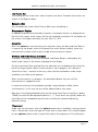
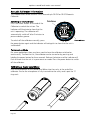
Mikrofonin ja esivahvistimen kytkentä
Kaikki Optimus mittarit toimitetaan irroitettavalla esivahvistimella joka on yhdistettävä mittariin ennen
käyttöä.. Esivahvistin kytketään mittarin päähän käyttäen lukitusruuvia.
1. Aseta esivahvistin mittarin liittimeen
2. Varmista, että liitin on paikallaan
3. kierrä lukitusruuvi kiinni
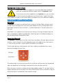
Älä kierrä väkisin, varo rikkomasta kierteitä. Kierteen
vahingoittumista ei takuu korvaa.
Jos mittari on kytketty päälle ilman esivahvistinta tai esivahvistin
irroitetaan mittarin ollessa päällä, näytöllä näkyy virhesignaali:
10/29
Esivahvistimen poisto
Älä kierrä esivahvistimen runkoa. Kierrä lukitusruuvi auki ja vedä esivahvistin ulos liittimestä.
Mikrofonin jatkokaapelin käyttö
Optimus mittareissa voi käyttää jatkokaapelia mittarin ja esivahvistimen välillä. Mittari on kalibroitava
kaapelin kanssa. Kytke kaapeli kuten esivahvistin edellä
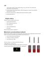
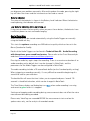
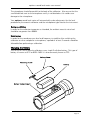
Paristojen asennus
Mittarissa käytetään 4 kpl AA paristoja
Suositellaan käytettäväksi alkaaliparistoja. Voidaan myös
käyttää Lithium AA paristoja ja myös ladattavia AA
paristoja.
Irrpoita paristokotelon kansi ruuvaamalla ruuvi auki ja
aseta paristot kuvan mukaan.
Huomaa napaisuus.
Aseta kansi paikoilleen
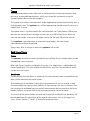
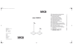
Paristojännitteen näyttö
Optimus mittarit näyttävät paristojännitteen näytön
oikeassa yläkulmassa.
Kun paristot ovat uusia, näyttö on vihreä ja kaikki segmentit ovat täynnä.
Kun paristoja käytetään, niiden teho pienenee ja paristojännitteen näyttö muuttuu. Kun jännite laskee
niin, että viimeinen segmentti on enää näkyvissä, väri muuttuu punaiseksi. Tässä vaiheessa on
suositeltavaa vaihtaa paristoja.
Mikäli paristoja ei vaihdeta ja jännite laskee edelleen, alkaa jännitteen näyttö vilkkua. Tällöin ei enää
11/29
voida olla varmoja, että mittaustulokset ovat oikeita.
Suosittelemme, että pidät varaparistoja aina mukana.
Jos virta kytketään paristojen oollessa liian eikkoja, alkaa näyttö vilkkua ja laite ei käynnisty.
Ulkoinen virransyöttö
Optimus mittaria voidaan käyttää myös ulkoisesta
jännitelähteestä. Voit käyttää tietokoneen USB liityntää tai
erillistä USB jännitesyöttöä.
Kun ulkoinen syöttö on kytketty, näytöllä näkyy USB symboli
parsitojänitteen ilmaisimen vieressä.
Kun ulkoinen jännitelähde on kytketty, optimus käyttää tätä,
eikä raasita siäisiä paristoja.
Ensiasetukset
Tee nämä ensiasetukset ennen kuin alat käyttää mittaria
Aika ja päivämäärä esitys
Kaikkiin mittauksiin tulee aikaleima. Tarkista että ajan esitys vastaa tarpeitasi.
Muuta: Menu > Set Date Time Formats
Kielen valinta
Valitse kieli: Menu > Set Language
Muistiin tallennuksen taajuus
Optimus tallentaa Leq, Peak(C), Lavg ja TWA arvot
Lisäksi mittari tallentaa muita tietoja mittauksen aikana. Tämä tieto voidaan lukea Noise Tools
ohjelmistolla tietokoneeseen jatkokäsittelyä varten.
Oletusarvo on 1 s.
Muuta: Menu > Storage > Time History Rate
12/29
Aikapainotus
Aikapainotusta vaihdetaan mittauksen tarkoituksen mukaan jotta saadaan kulloisten vaatimusten
mukainen mittaustapa.
Muuta: Menu> TimeWeighting (F,S,I)
F = nopea, S = hidas, I on impulssi
Integrointiasetukset
Integrointiasetuksia käytetään Dose moduulin toiminnan ohjaukseen
Muuta : Menu> Quick settings
Äänitasonäytön väri
Äänitasonäyttöpylvään väri voidaan muuttaa vaihtumaan vihreästä keltaiseen ja vihreästä punaiseen
asetetuilla äänitasoilla.
Muuta: Menu > SetLevel Colours
Muistin tyhjennys
Tiedonkeruulla varustetut mittariversiot omaavat 4 GB muistikapasiteetin, joka sallii yli 10000
mittauksen tallentamisen.
Muistin voi tyhjentää: Menu > Storage > Clear Memory
Voice Tag
Voit kytkeä äänen tallennuksn päältä: M>nu VoiceTag
13/29
Mittaaminen
Käynnistys
Esivahvistimen on oltava kytkettynä. Suosittelemme esivahvistimen kytkenmistä
virrattomaan laitteeseen.
Kytke mittari päälle virtakytkimestä mittarin vasemmalla sivulla. Näytölle tulee
ensin käynnistysnäyttö jonka jälkeen mittari kytkeytyy viimeksi käytettyyn
näyttöön.
Mittarin kalibrointi
Mnittari tulisi kalibroida ennen jokaista käyttöä ja myös jokaisen käytön jälkeen. Tällä voidaan
varmistaa, että mittari on ollut kunnossa mittauksen aikana.
Huomaa., että mikrofonikapseli on erittäin herkkä ja sitä on käsiteltävä varoen. Älä koputa
äläkä pudota mikrofonia. Jos epäilet, että mikrofoni on vaurioitunut ota yhteyttä myyjään.
Jos käytät kaapelia, mittari on kalbroitava kaapelin kanssa.
Kalibrointi:
1. Aseta kalibraattori varovasti mikrofonin päälle japaina painiketta kalibraattorin pohjassa.
2. Paina Calibrate painiketta.
Mittari mittaa kalibraattorin antamaa äänitasoa. Kalibraattorin antaman tason on oltava 94 dB
+/- 0.075 dB 5 sekunnin aja jotta kalibrointi onnistusi
3. Kun kalibrointi on suoritettu, mittari näyttää tason sekä korjauksen suuruuden. Paina Ok
palataksesi kalibroinnista.
Jos kalibraattorin antama taso ei ole odotetun suuruinen, kalibrointi ei onnistu ja mitään säätöä ei
suoriteta. Paina Cancel palataksesi-
14/29
Tuulisuojan käyttö
Optimus mittaria voidaan käyttää UA237 90 mm vaahtomuovisella tuulisuojalla, joka vähentää tuulen
aiheuttamaa ääntä. Sitä voidaan käyttää myös estämään lian tunkeutumista mikrofoniin ja se suojaa
mikrofonia myös kolhuilta.
Mittauksen aloitus
Aloita mittaus painamalla Start.
Jos VoicTag toiminto on kytkettynä, Voice tAg näyttö tulee esiin. (vain tiedonkeruulla varustetut
mittarit)
VoiceTag äänikommentti
Voit tallentaa max 30 s ääniviestiä esimerkiksi mittauskohteen kuvaamiseen
ja muiden olosuhteiden tiedottamiseen. Painama Record painiketta ja puhu
mikrofoniin. Kun olet valmis paina Done
Voit ohittaa tämän painamalla Skip painiketta.
Jos tallennusaika ylittää 30 s, vastaanotettu puhe tallennetaan muistiin ja
mittari siirtyy mittaukseen.
Mittaustuloksen katselu
Kun mittaus on aloitettu punainen ikoni näytön vasemmassa yläkulmassa
ilmaisee mittauksen olevan käynnissä.
Mittari mittaa nyt tietoa kaikkiin saatavissa oleviin toimintoihin
riippumatta valitusta nääytöstä.
Keltaiset nuolet näytöllä osoittavat mistä saatavissa olevat näyttötilat ja
näyttösivut ovat löydettävissä
Vasen/ oikea painikkeet valitsevat näyttötilan
Ylös/alas nuolet valitsevat näyttötilan sivun
15/29
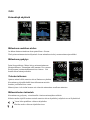
Esimerkkejä näytöistä
Mittauksen uudelleen aloitus
Jos haluat aloittaa mittauksen alusta paina Menu > Restart
Tämä poistaa mittausmuistista käynnissä olevan mittauksen tiedot ja asettaa mittausajan nollaksi.
Mittauksen pysäytys
Paina Stop painiketta, Mittari siirtyy mittaustoiminnosta.
Muistitoimintoon. Tietonauhan teksti muuttuu View sanasta
Recall sanaan ja mittausindikaattorin kuva katoaa.. Voit
katsella äsken mitattuja tuloksia.
Tulosten tallennus
Optimus mittaa kaikki saatavissa olevat äänisuureet yhtaikaa,
Kun mittaus pysäytetään kaikki tieto tallennetaan muistiin
katselua ja muistiin lukua varten.
Mittarit joissa ei ole tiedon keruuta vain viimeisin mittaustieto on tallessa mittarissa.
Mittaustulosten tarkastelu
Kun mittaus on pysäytetty voit tarkastella viimeisen mittausjakson tuloksia
Keltaiset nuolet näytöllä osoittavat mistä saatavissa olevat näyttötilat ja näyttösivut ovat löydettävissä
Vasen/ oikea painikkeet valitsevat näyttötilan
Ylös/alas nuolet valitsevat näyttötilan sivun
16/29
Alla esimerkkejä näyttötiloista
Paina Exit painiketta kun haluat poistua tulosten tarkastelusta
Tulosten lukeminen mittarin muistista
Muistista lukemeninen käynnistyy: Menu > Storaage > Recall From Memory
Viimeisin mittaus näkyy näytöllä. Askella näyttöjä nuolipainikkeilla kuten edellä.
Alhaalla näkyy mittauksen numero. Tallentuvien mittausten luku riippuu laitteen kokoonpanosta
Exit painikkeella poistutaan muistin luku toiminnosta.
Läitteen poiskytkentä
Paina virtakytkintä kunnes näytöllä näkyvä vihreä vaakapalkki täyttää
ruudun.
Laite kytkeytyy tämän jälkeen virrattomaksi.
17/29
Moduulit
Optimus mittarit ovat modulaarisia, jonka vuoksi mittaria voi täydentää tarpeen vaatiessa lisäämällä
siihen toimintomoduuleja.
Optimus mittarit mittaavat tietoka yhtaikaisesti kaikissa asennetuissa moduuleissa riippumatta sen
hetkisestä näyttötilasta.
Esimerkiksi mittari CR:162C sisältää moduulit General ,Sound Level, Leq, Octaavikaistat ja Dose
(annos) moduulit.
Keikki moduulit eivät ole saatavissa kaikissa mittarimalleissa.
Kukin moduuli omaa oman näyttötilansa (View)
Moduulien toiminnot
General View
Tämä näyttötila on kaikissa mittareissa
Sivu 1:
•
Muistissa olevien mittausten luku
•
Vapaa muistikapasiteetti
•
Kalibroinnin Offset
•
Kalibrointipäivä akustisella kalibraattorilla
•
Kalibrointiaika
Sivu 2
•
Mittarin tyyppi
•
Mittarin sarjanumero
•
Laitteiston versio
Sivu 3
•
Laitteen täyttämät standardit
Sivu 4
•
Laitteessa olevat moduulit
18/29
Sound level View
Tämä näyttötila on saatavissa kaikissa mittareissa ja näyttää äänitason eri aika- ja taajuuspainotuksissa
Kun mittari ei ole mittaamassa, näytetään kolmella sivulla (askella ylös/alas nuolilla)
Äänitaso LAF, LCF, LZF (Aikapainotus muutettavissa Menu painikkeella)
Kun mittari mittaa, (Start painettu)
Äänitaso LAF, LCF, LZF (Aikapainotus muutettavissa Menu painikkeella)
Maximit
Minimit
Mittauksen kesto
Leq View
Leq on saatavissa mittareihin optimus punaisiin CR:162 ja CR:161 versioihin
Kun mittari ei ole mittaamassa näytetään
LAeq,LCeq ja LZeq omilla sivuillaan
Kaavio Laeq ja LaePeak
Kun mittari mittaa (Start painettu)
LAeq,LCeq ja Lzeq ,LZPeak, Lceq-LAeq, LAE, LCE, LZE
Kaavio Laeq ja LaePeak
Mittauksen kesto
Oktaavikaistat
Okttavikaistat ovat saatavilla CR:161C ja CR:162C mittareissa
Kun mittari ei mittaa
Kaavio näyttää reaaliaikaiset oktaavikaistat Lf sivulla 1
Oktaavikaistojen Leq tasot numeroina sivulla 2
Kun mittari on mittaamassa
Kaavio nääyttää kaistan maksimiarvoa Lf
Numeerinen Leq 1 s reaaliarvoa (päivitys 1 s välein)
Kaavio kumuloituneesta Leq arvosta
Numeerinen esitys kumuloituneesta arvosta
19/29
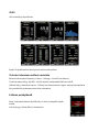
Dose View
Dose View eli meluannos on kaikissa Optimus punaisissa mittareissa.
Kun mittari ei suorita mittausta
Vain Leq – arvo on näytöllä
Kun Mittari suorittaa mittausta
UK pika-asetus
Laeq
LEPd
altistus Pa2h
Arvioitu altistus
Laskennallinen altistustaulukko
EU pika-asetus
Laeq
Lex.8h
altistus Pa2h
Arvioitu altistus
Laskennallinen altistustaulukko
OSHA HC PEL Pika-asetus
Laeq
Lex.8h
altistus Pa2h
OSHA HC
Arvioitu altistus
Lavg
TWA
Dose%
Arvioitu Dose%
OSHA PEL Lavg
TWA
Dose%
Arvioitu Dose%
OSHA HC & ACGIH Quick Setting
LAeq Lex,8h Exposure in Pa2h
Estimated Exposure in Pah
OSHA HC Lavg TWA Dose% Estimated Dose %
ACGIH Lavg TWA Dose% Estimated Dose %
MSHA HC & EC Quick Setting
LAeq Lex,8h Exposure in Pa2h Estimated Exposure in Pa2h
MSHA HC Lavg TWA Dose% Estimated Dose %
MSHA EC Lavg TWA Dose% Estimated Dose %
20/29
Mittarin asetukset
Menu valikossa on toimintoja, jossa mittarin asetuksia voi muuttaa. Painamalla Menu painiketta
päästään valikkoon, josta voi askeltaa halutulle kohdalle ja valita toiminnon käyttöön.
Jotku toiminnot eivät ole aina käytettävissä, esim mittauksen aikana. Tämä näkyy näytön alaosassa
tekstinä ” Not available”
Voimassa oleva asetus näkyy näytön alaosassa
Aikapainotus
Valittavana on Nopea, Hidas ja Impulssi((Fast Slow ja Impulse) Mittari mittaa näitä kaikkia yhtaikaa ja
kun tiedonkeruu toiminto on asennettuna, ne myös tallentuvat muistiin.
Näytöllä näkyvä aikapainotus voidaan valita milloin tahansa
Pika-asetuksissa valittu påika-asetus määrää aikapainotuksen
Valitse haluamasi asetus ja paina OK hyväksymisen merkiksi
Pika-asetukset
Mittarissa on kolme integraattoria, johon voidaan tallentaa äänitasojen kertymiä. Integraattori 1 kerää
Leq 3 dB vaihtotaajuudella ja integraattorit 2 ja 3 voidaan ohjelmoida pika-asetuksilla tai NoiseTools
ohjelmistolla. Integraattorien 2 ja 3 tulokset näkyvät Dose View näyttötilassa.
Määrättyjen standardoitujen mittausten suorittamiseksi on mittariin ohjelmoitu pika-asetuksia:
UK
EU
3dB, No Threshold, No Time Weighting, Criterion Level of 85dB
3dB, No Threshold, No Time Weighting, Criterion Level of 85dB
OSHA HC & PEL
Integrator 2 5dB, 80dB Threshold, Slow Time Weighting, 90dB Criterion Level
Integrator 3 5dB, 90dB Threshold, Slow Time Weighting, 90dB Criterion Level
OSHA HC & ACGIH
Integrator 2 5dB, 80dB Threshold, Slow Time Weighting, 90dB Criterion Level
Integrator 3 3dB, No Threshold, Slow Time Weighting, 85dB Criterion Level
MSHA HC & EC
Integrator 2 5dB, 80dB Threshold, Slow Time Weighting, 90dB Criterion Level
Integrator 3 5dB, 90dB Threshold, Slow Time Weighting, 90dB Criterion Level Custom
Custom settings defined by the NoiseTools software
21/29
Kellon asetus
Optimus mittarissa on reaaliaikakello ja kalenteri, joka antaa kaikille mittauksille aikaleiman.
Kello asetetaan aikaan SetClock toiminnolla. Asetus tapahtuu nuolipainikkeilla.
Voice Tag
Voice Tag toiminto mahdollistaa puheen tallennuksen mittaustulosten yhteyteen. Tällä tavoin voit
tallentaa kommentteja ja tietoja mittauksesta puolen minuutin ajan mittausta kohden.
Tässä valikossa voit asettaa toiminnon päälle tai pois.
Äänitason värit. (Colors)
Näytön vasemmalla sivulla oleva pylvös ilmoittaa hetkellisen äänen tason. Tässä toiminnossa voit
asettaa tasot joissa näyttö vaihtaa väriä vihreästä keltaiseen ja punaiseen. Asetus tapahtuu
nuolipainikkeilla. Paina OK lopuksi.
Kielen valinta (Language)
Voit valita näytön kielen halutuksi. Valitse kieli painikkeilla ja paina OK
Muisti (Storage)
Tiedon keruulla varustetun mittarin muistiin mahtuu 10000 mittausta.
Optimus mittari tallentaa jokaisesta mittauksesta kaiken mitatun ja lasketun tiedon riippumatta mitä
näyttötapoja on käytetty.
Muistin voit tyhjentää Clear Memory toiminnolla. Esimerkiksi kun olet lukenut mittaustulokset
tietokoneelle. Täyden muistin tyhjennys kestää jopa 5 minuuttia.
Time History data Rate
Tiedon keruulla varustetut mittarit keräävät tietoa määrävälein, joka on pletusarvoisesti 1 s
Voit valita muita aikavälejä välillä 10ms..2 s alueella
Oktaavikaistoja minimitallennusväli on 0.5 s.
Valitse haluttu aikaväli ja hyväksy OK painikkeella
Näytön kirkkaus (Screen Brightness)
Optimus mittarissa on automaattinen kirkkauden säätö ulkoisen valaistuksen mukaan. Voit muuttaa
säädön manuaaliseksi valitsemalla Fixed ja säätämällä kirkkauden halutuksi.
22/29
Screen Saver ( Näytön säästäjä)
Jos mitään painiketta ole painettu 3 minuutin sisällä, Näyttö siirtyy säästötilaan ja palutuu kun jotain
painiketta painetaan. Muuta painikkeilla ja hyväksy OK painikkeella.
Set Date@ Time Formats (Ajan esitysmuoto)
Oletusarvo on dd/mm/yy hh:mm:ss.
Voit valita muita esitysmuotoja valikosta. Paina OK lopuksi
Restore Factory settings (Palauta tehdasasetukset )
Asetukset voidaan palauttaa tehdasasetuksiksi : Kieli Englanti, Pika-asetus UK
Projected Exposure Calculation
An optimus red sound level meter is the ideal instruments for measuring noise to the UK
Control of Noise at Work Regulations. All of the functions needed to meet these regulations
are available quickly and easily through 2 main screens.
If the instrument is set, via the Quick Settings, to the UK option, a further screen is available
as part of the Dose View.
The Lep,d value shown is calculated from the current LAeq and the current elapsed time.
Where the run time is short or the LAeq value is low, the calculated Lep,d value will also be
low. This is not unusual and is the correct calculation of the Lep,d.
Lep,d is defined by the UK Noise at Work Regulations as “the total personal noise exposure
to noise at work (this figure is normalised to an 8 hour day), taking into account of the average
levels of noise in working areas and the time spent in them, but taking no account of any ear
protectors (earmuffs or earplugs) worn.”
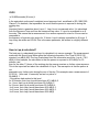
Basically, Lep,d is a measured Leq value expressed as an 8 hour. The formula to calculate
Lep,d is:
Where T
is the duration of the person’s working day in seconds T
e
23/29
is 28,800 seconds (8 hours) L
0
is the equivalent continuous A-weighted sound pressure level, as defined in ISO 1999:1990
Clause 3.5 in decibels, that represents the sound that the person is exposed to during the
working day.
Aeq,Te
Important facts to remember about Lep,d: 1. Lep,d is not a measured value. It is calculated
from the Exposure Time and from the measured Leq value. 2. Lep,d is normalised to an 8
hour day. This means that a measurement for a worker exposed to noise for 8 hours can be
compared to
the exposure of a person who works for 12 hours. Lep,d is always normalised to 8 hours. 3.
Lep,d may be written as LEX,8h This is the same parameter, but written in a slightly different
way.
How is Lep,d calculated?
The best way to understand how Lep,d is calculated is to use an example. The measurement
made with the Sound Level Meter gives the following information: Run Time 00:30:00 (30
minutes) Leq dB(A) 90.0 The Lep,d calculated from this information would be: Lep,d = 78.0
dB(A) In this example, the calculation is that the person is exposed to 90.0 dB(A) for 30
minutes, and
then for the other 7½ hours of the working day the person receives no further noise exposure.
This is the important fact about the calculation of Lep,d. The assumption is that the person is
not
exposed to any further noise during the rest of the day. This example uses a measurement of
01:00:14 ( 1 hour and 14 seconds) and an Leq value of
99.8dB(A). 1.
If the person had worked in this level
for 30 minutes, their Lep,d would have been 87.8 dB(A) 2.
for 1 hour, their Lep,d would have been 90.8 dB(A) 3.
for 2 hours, their Lep,d would have been 93.8 dB(A) 4.
for 4 hours, their Lep,d would have been 96.8 dB(A) 5.
for 6 hours, their Lep,d would have been 98.6 dB(A) 6.
for 8 hours, their Lep,d would have been 99.8 dB(A)
24/29
Mittausten tallentaminen Noise Tools ohjelmalla
Tiedon keruulla varustetut mittarit voivat siirtää mittaustulokset Noise Tools ohjelmistoon.
Optimus mittarissa on USB 2.0 vaatimus
Noise Tools ohjelmiston asennus
Asenna ohjelmisto ennen mittarin kytkentää tietokoneelle.
Noise Tools toimii windows XP, Vista ja 7 käyttöjärjestelmillä
Ohjelmiston käyttö
Käynnistä ohjelma ennenkuin kytket mittarin. Kytke mittari mukana seuraavalla USB kaapelilla.
Toimi ohjelman antamien ohjeiden mukaan.
Tekniset tiedot
Yleiset
25/29
26/29
27/29
28/29
29/29
User manual for
optimus sound level
meters
optimus sound level meter user manual
Page 2
optimus sound level meter user manual
About this manual
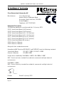
• The instructions in this user manual refer to the operation of Cirrus Research plc
optimus sound level meters with version 2.4 or higher of the firmware.
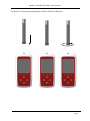
• The instruments described in this manual are the optimus yellow (CR:150
series), optimus red (CR:160 series), optimus green (CR:170 series) and
optimus purple (CR:190 series).
• Some functions described in this manual are only available on red or green
versions of the optimus sound level meters. Where functions are applicable to
only some instruments in the range, this will be clearly indicated in the text.
• In this manual, “optimus” is used as a general reference for the optimus sound
level meters and “calibrator” is used as a general reference for an acoustic
calibrator.
• This manual describes the recommended usage of the optimus. Any warnings
will be indicated by
• The additional information required for testing in accordance with IEC 61672 is
provided as a supplementary document, Optimus Sound Level Meters
Technical Data Part B, which is available for download at
www.cirrusresearch.co.uk/library/optimus
• It is not possible to change the way that the instrument measures through the
software or firmware. Any legal metrology aspects of the instrument cannot be
affected by any changes made in the instrument.
• The Common Specifications section on page 30 defines which standards relate
to the different functions available in the instruments. Additional approvals and
certifications may apply to the instruments and these will be listed in the
Appendices.
• More detailed explanations of the audio recording templates, tonal noise
detection and the repeat measurement timers are available to download from
the Cirrus website at www.cirrusresearch.co.uk/library/optimus
• Quick Start Guides for the optimus sound level meters can be downloaded
from the Cirrus website at www.cirrusresearch.co.uk/library/optimus
Page 3
optimus sound level meter user manual
Copyright
Copyright © Cirrus Research plc 2010-2013
All rights reserved.
You may re-use this document/publication (not including the Cirrus Research plc logo
and other product logos) free of charge in any format for research, private study or
internal circulation within an organisation. You must re-use it accurately and not use it
in a misleading context.
You must not modify text, images or illustrations in any way. The material must be
acknowledged as Cirrus Research plc copyright and you must give the title of the
source document/publication.
Where any third party copyright material is identified you will need to obtain
permission from the copyright holders concerned.
Trademarks
Cirrus Research plc, the Cirrus Research plc Logo, doseBadge, DOSEBADGE, optimus,
the NoiseTools Logo and the Noise-Hub Logo are either registered trademarks or
trademarks of Cirrus Research plc in the United Kingdom and/or other countries.
Microsoft and Windows are registered trademarks of Microsoft, Inc. All other
trademarks acknowledged.
Updates
In the interests of continuous product improvement, Cirrus Research plc reserves the
right to make changes to product specifications without notice.
To understand the latest updates that have been implemented into this product and to
download the most current version of this user manual, visit our web site at
www.cirrusresearch.co.uk
Issue 2.2
Page 4
February 2013
optimus/12/13/22EN
optimus sound level meter user manual
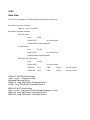
Introduction ................................................................................................................................ 8
First Use .................................................................................................................................... 10
Inserting the batteries ....................................................................................................................... 12
Calibration.......................................................................................................................................... 13
Making a measurement ............................................................................................................ 15
Operations in more detail ......................................................................................................... 16
NoiseTools ......................................................................................................................................... 16
Keypad and Controls.......................................................................................................................... 16
Connectors......................................................................................................................................... 17
Screen saver ...................................................................................................................................... 18
Display ............................................................................................................................................... 18
Audio Recording ................................................................................................................................ 20
Timers ................................................................................................................................................ 21
Back Erase/Pause............................................................................................................................... 21
Memory ............................................................................................................................................. 22
Restore Factory Settings .................................................................................................................... 22
Windshield ......................................................................................................................................... 22
Getting to know your optimus – features and capabilities ...................................................... 23
Views ................................................................................................................................................. 23
High Level Noise Measurement ......................................................................................................... 25
Menus ....................................................................................................................................... 26
Additional Information .............................................................................................................. 29
Appendices ............................................................................................................................... 30
IEC 61672 test data ............................................................................................................................ 30
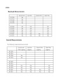
Common Specifications...................................................................................................................... 30
Views ................................................................................................................................................. 32
Stored Measurements........................................................................................................................ 35
Electrical Outputs ............................................................................................................................... 37
Acoustic Calibrator Information ................................................................................................ 40
Calibrating a Sound Level Meter. ....................................................................................................... 40
Changing the Battery ......................................................................................................................... 41
Specifications ..................................................................................................................................... 42
Technical Information ........................................................................................................................ 42
CE Certificate of Conformity...................................................................................................... 44
Warranty ................................................................................................................................... 45
Index ......................................................................................................................................... 46
Cirrus Research Offices ............................................................................................................. 47
Page 5
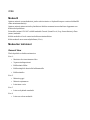
optimus sound level meter user manual
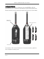
Microphone Capsule
Preamplifier
Preamplifier Locking Ring
Ambient Light Sensor
Leq View
140
LAeq,1s dB
Display
LC Peak 89.3dB
C-A
3.5dB
140
100
60
20
Short LAeq
1 of 3
20
LAS
LCPeak
07/01/10 09:43:21
Start
Soft Keys
Control Keys
Page 6
Menu
Calibrate
optimus sound level meter user manual
Battery Cover Retaining Screw
On/Off Button
Cirrus
Research plc
Battery Cover
Tripod Mount
Page 7
optimus sound level meter user manual
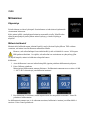
Introduction
Welcome to your optimus sound level meter. This next-generation instrument from
Cirrus Research plc is powerful yet simple to use, and is capable of a wide range of
noise measurement functions.
The advanced technology used in the optimus
instruments does not get in the way of you making
effective noise measurements, and the large, clear
screen makes it easy to read the comprehensive
information on the display.
The optimus makes your noise measurements simple:
Measure everything and forget nothing
One of the key aims of the optimus instruments is to
give you a sound level meter that is as simple to use
as possible whilst providing the very highest level of
performance and function.
You cannot forget to measure the right function as
everything is measured at the same time.
For example, if you’ve chosen the Fast time weighting
View Option, the optimus will still measure Slow and
Impulse at the same time.
You can choose another time weighting View Option
from the menu, and then see real-time data or review
stored measurements using the new parameters.
This applies to all other noise parameters (excluding
Dose - for further details, see page 25).
The optimus measures them all, and you can choose
your View Option to review the data.
VoiceTag audio recording
The data logging versions of the optimus feature the VoiceTag audio recording
function.
Page 8
optimus sound level meter user manual
This allows you to record notes and information before a measurement by simply
speaking into the microphone, then play them back later in the NoiseTools software.
You can save time when making measurements, and remove the need to carry a
notepad and store any important information about your measurements.
A single measurement range
By using the very latest in digital technology combined with 40 years’ experience in
designing sound level meters, we have given the optimus instruments the ability to
measure from 20dB(A) to 140dB(A) and up to 143dB(C) Peak in a single span.
This means that there is no need for you to choose which range you may need for
your measurement, and that there is almost no chance of the instrument overloading
or under-ranging.
A clear, simple display of the information you need
The display used on the optimus is a high resolution colour OLED type. This gives a
clear, bright display that is easy to read in all light conditions as well as allowing us to
use colour to show specific functions and information.
All of the information that you need is shown clearly on the screen with the most
useful function, for example the Leq in the Leq View, shown in large white text. This
makes it easy for you to see the information that is important at a glance.
A modular design to future proof your investment
The optimus instruments are based around a modular design which allows you to
upgrade and update your instrument if and when the time arises.
This means that your instrument will meet your current and future needs, no matter
what you need to measure.
Audio Recording during measurements
The optimus green instruments can record and store audio data (the actual sounds
heard by the microphone) during a measurement.
This data can be downloaded along with the noise measurements for analysis and
review and can be used to identify the source of the noise.
Audio recordings can be started either manually or automatically using a set of
triggering rules.
Page 9
optimus sound level meter user manual
First Use
Your optimus sound level meter has been shipped in reusable packaging that should
be retained for safe shipment when returning the instrument for calibration or
servicing.
All optimus meters come with the following standard accessories:
•
•
•
•
•
•
•
MV:200 Microphone Preamplifier
Microphone capsule (attached to the preamplifier)
Wrist
4 x AA batteries
User Manual
Product CD (with NoiseTools software and documentation)
Windshield
You may have other accessories, depending on your package. Please check for
damage or missing items before using your optimus.
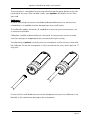
All optimus instruments are shipped with the removable preamplifier separated from
the body. When connecting the preamplifier, please take great care to only turn the
locking ring at the base.
Twisting the preamplifier body is likely to cause serious damage. The microphone
capsule is also delicate, and care needs to be taken when handling.
Damage caused by misuse is not covered by the warranty for the instrument.
Page 10
optimus sound level meter user manual
To connect or remove the preamplifier, please follow the diagram:
Page 11
optimus sound level meter user manual
Inserting the batteries
Your optimus is powered by 4 x AA batteries (also called MN1500 or LR6). We
recommend that you use alkaline or lithium batteries to give the best performance.
Remove the battery cover by loosening the captive locking screw (as shown below).
Battery Cover
Retaining Screw
Battery Polarity Indicators
Cirrus
Research plc
Battery Cover
Please look carefully at the diagram inside the battery compartment showing the
correct polarity. After inserting the batteries in the correct orientation, replace the
cover and tighten the locking screw.
Page 12
optimus sound level meter user manual
The instrument is switched on by pressing and releasing the power button on the left
hand side of the case. After the boot screen, your optimus will display the last View
you used.
Calibration
All noise measuring instruments should be calibrated before each use, because the
microphone is susceptible to minor damage from even small knocks.
The calibration applies corrections (if needed) to ensure that your measurements are
as accurate as possible.
Calibration should also be carried out at the end of a measurement session to make
sure that nothing has happened to the instrument during the session.
To calibrate your optimus, carefully push the microphone into the cavity at the end of
the calibrator. Ensure the microphone is fully inserted into the cavity and is past the ‘O’
ring seals.
Ensure that the small bleed hole next to the microphone cavity on the calibrator is not
blocked, as this could cause damage to the microphone.
Page 13
optimus sound level meter user manual
Take care not to use a twisting motion when pushing the microphone into the
calibrator, as this is likely to cause damage to the preamplifier (as described earlier in
this chapter).
Press the ‘on’ button on the end of the calibrator. Press the calibrate button on the
optimus.
The instrument will measure the sound level from the acoustic calibrator to determine
if it is within the required tolerance and levels. The calibration level must be stable to
within ±0.075dB for 5 consecutive seconds for the calibration to be successful.
When the calibration is completed, the optimus will display the level along with the
correction or adjustment made.
The optimus is preset with the correction values needed for Cirrus Research
microphone capsules, so no manual adjustment is required. The calibration level you
should expect is 93.7dB.
Refer to page 40 for detailed operating information for the CR:514 and CR:515
Acoustic Calibrators.
Page 14
optimus sound level meter user manual
Making a measurement
Press the Start key to begin recording (on data logging intruments with the VoiceTag
function switched on, the VoiceTag screen will show – press skip to move on without
recording a note).
Your optimus is now measuring and recording noise data for all available functions,
regardless of your selected View, and the red animated Running icon will show in the
top left of the information bar.
The measurement can be paused by pressing the Pause/Stop soft key .
Press once to pause/back erase and twice to stop, or alternatively press and hold for
three seconds to stop. (For Pause & Back Erase, see page 21).
The Pause/Back Erase function is only available if this has been enabled in the
instrument menu.
To stop the measurement, press the Stop key. The instrument will change from
measurement to review mode, and your data is stored and ready to review and
download. For instruments without data logging, only the last recorded measurement
is available for review.
Page 15
optimus sound level meter user manual
Operations in more detail
Please note: from this chapter on, the manual describes capabilities
which are available on different models within the optimus range.
If you are unsure which capabilities your optimus has, you can check
on the instrument by looking at the General View / page 5 (and 6 on
some models), or look at the Features Matrix available on the Cirrus Research website:
www.cirrusresearch.co.uk/optimus/library
NoiseTools
All optimus instruments are delivered with a copy of the NoiseTools software which
can be used to configure the instrument (some options are only configurable within
NoiseTools and not on the instrument – it will be made clear in the text where this is
the case).
NoiseTools is also a powerful environment for storing, analysing and organising your
data, and produces reports for publication. VoiceTag notes and audio recordings can
only be played back through NoiseTools.
Keypad and Controls
The optimus is controlled via the four arrow keys (up, down, left and right) and three
soft keys, which change in function depending upon the mode that the instrument is
in. The soft key function is shown above the button on the display.
The left and right keys move between the Views and the up and down keys move
between the pages of each View.
The ambient light sensor on the front of the instrument will illuminate the keypad and
adjust the brightness of the display automatically when the light level falls.
When the pause function has been activated (described on page 27), the right soft key
toggles between pause and stop. Press once to pause/back erase and twice to stop, or
alternatively press and hold for three seconds to stop.
Page 16
optimus sound level meter user manual
Connectors
The connectors used by the optimus to communicate with a PC and NoiseTools are at
the bottom of the instrument under a protective cover.
Open by pulling this edge
Protective Cover
3.5mm Socket
AC Output
USB Connector
Multi I/O Interface Connector
RS232 & DC Output
Wrist Strap Fastening Pin
The optimus can be powered via the multi-pin connector on the bottom of the
instrument. Power can be connected using a ZL:171 optimus power input cable
(2.1mm Power Jack, 2m) or via ZL:176 optimus 12v Battery pack cable.
The optimus can also be powered from an external source, such as a USB connection
to a PC or via a USB power supply.
External Power via USB
140
140
Leq View
Leq View
LAeq,1s dB
LC Peak
89.3dB
LAeq,1s dB
C-AP k 893 3dB
5dB
LC
External Power via Multi-Pin Connector
140
140
Leq View
Leq View
LAeq,1s dB
LC Peak
89.3dB
LAeq,1s dB
C-AP k 893 3dB
5dB
LC
Page 17
optimus sound level meter user manual
An AC output is available on the optimus via the 3.5mm jack socket. The output is unweighted and the output level can be adjusted using the options in the AC Out menu.
This output can be used with external instrumentation. See page 37 for details of the
electrical outputs.
Screen saver
If no keys are pressed for 6 minutes the display will dim to preserve battery and
screen life, and reduce power consumption. After 30 minutes with no key presses the
display will switch off completely and keypad flashes every two seconds to show that
the instrument is powered. The screen dim and screen saver functions will occur
during measurements as well as when not measuring. Press any key to restore the
display.
The time intervals for the screen dim and screen saver are configurable in NoiseTools.
Display
The optimus uses a high resolution colour OLED screen to show a clear and easy to
read display of all the information you need.
Audio Recording
Trigger Ready
External/USB Power
Timer Mode Active
Audio Recording
Running
Navigation Bar
Battery Level Indicator
Measurement
Run Indicator
Information Bar
Leq View
Primary Function
Secondary Functions
Measurement Display
Time History Chart
Analog
Bar
Short LAeq
LCPeak
1 of 3
Status Bar
Soft Key Bar
07/01/10 09:43:21
Start
Menu
Soft Keys
Page 18
Calibrate
Page Up/Down
optimus sound level meter user manual
Information Bar
The information bar shows icons when functions are active. Examples of the icons are
shown in the diagram above.
Navigation Bar
The navigation bar shows which View or Menu you are looking at.
Measurement Display
In addition to primary and secondary functions, the display features an Analog Bar on
the left of the screen, which shows real time A-weighted sound level. At the bottom of
the screen is the Page information for your View, ie 1 of 3.
Status Bar
When the optimus is not measuring, the status bar shows the date and time. When it
is measuring, the display shows the elapsed time and in Review mode it shows the
measurement number and the total number of measurements stored.
Overload and Under-Range Indication
Overload is indicated by the word 'overload' and Under-Range is indicated by the
word ‘under range’ (in the chosen language) on the display.
On the Sound Level View and Leq View the indicators are situated beneath and to the
left of the large number. When a measurement is not in progress, the indicator is
shown for at least 1 second, so that very short transient overload or under-range
conditions are visible to the operator.
When a measurement is in progress, the overload indicator stays on until the
measurement is stopped or reset.
In some circumstances the overload and under range indicators will be shown
simultaneously. In this case the text will be abbreviated to save space.
Note that if any displayed decibel value on the Sound Level View or Leq View is below
14.0dB, the value will be replaced by dashes ('---'). These levels are typically below the
noise floor of the microphone capsule and so will only be encountered during
electrical testing.
‘Bluescreen’
Under rare circumstances, when the optimus encounters a condition it cannot recover
from, a ‘bluescreen’ error message will show with an error code. If this should happen
to your optimus, please make a note of the code so the engineers at Cirrus Research
Page 19
optimus sound level meter user manual
can diagnose your problem accurately. After writing down the code, pressing the right
key will clear the screen and the instrument can be used as normal.
Battery indicator
The status of the batteries is shown in the Battery Level Indicator. When the batteries
need replacing, the indicator will turn red.
Low Battery Indication while switching on
If the start-up screen flashes quickly when you press the on button, the batteries have
insufficient power to start and need changing.
Audio Recording
Audio recording can be started automatically using the Audio Triggers or manually
using the Audio soft key.
This starts the optimus recording raw WAV data at a quality which can be set in the
Menu (Standard or Studio).
Details of the Audio Triggers can be found in Technical Note 28 - Audio Recording
with the optimus green sound level meters. Please refer to the Cirrus Research plc
website at www.cirrusresearch.co.uk/library/optimus.
Pressing the audio key again stops the recording. There is no maximum duration of an
audio recording set by default, but it can be changed in NoiseTools, and the
parameters for the Audio Triggers can be configured in NoiseTools.
The audio recording includes a 10 second back buffer (on the Standard quality setting).
When triggering a recording manually, it’s very difficult to record the beginning of a
sound that catches your attention.
The back buffer will cover the time it takes you to respond and press ‘record’. 10
seconds is the default duration, which can be changed in NoiseTools.
The Time History display and Analog bar turn blue when audio recording is running
and revert to green when it is stopped.
Starting and stopping audio recording during a measurement does not affect the noise
measurement data being recorded.
Please note, VoiceTags are recorded BEFORE the measurement starts and are for
spoken notes only, not for analysis of recorded sounds.
Page 20
optimus sound level meter user manual
Timers
The single and repeat timers allow you to make precisely timed measurements over
pre-set or custom defined durations, which are set on the instrument using the
Storage Options Menu (see next chapter).
The repeat timer allows measurements to be stopped and started automatically over a
long period of time. The optimus can still be stopped and started manually when the
repeat timer is active.
The repeat timer is synchronised to the real time clock, so if you choose a 30 minute
duration the measurement will begin on the hour or at 30 minutes past. When the
measurement ends, a new one will begin and last for the next 30 minute interval.
If the optimus is paused when an automatic timer begins, the new timed
measurement will also be paused.
Please note, after 5 minutes in pause the optimus will restart.
Back Erase/Pause
Pause
The optimus sound level meters provide Pause and Back Erase function which can be
used during a measurement.
When the Pause function is enabled in the menu, the Stop button is replaced by the
Pause/Stop button. This also enables the Back Erase function, the duration of which
can be set in the menu.
Back Erase
The Back Erase function allows a section of the measurement to be removed from the
data used to calculate the overall values.
An example of this would be if, during the measurement of cars on a road, a large
truck passed by the measurement location. If the intention was only to measure cars,
the truck can be excluded from the overall measurement data by pressing the Pause
button and then using the Back Erase to remove a preset section of noise.
The time that the pause button was pressed, along with the Back Erase duration, will
be excluded from the calculation of the overall noise values such as the Leq, Lmin,
Lmax, LPeak, and the 1:1 and 1:3 Octave Band overall values.
Page 21
optimus sound level meter user manual
The duration of the Back Erase can be set to between 1 and 30 seconds using the
menu and can also be configured in the NoiseTools software. If the Pause function is
disabled, the Back Erase function is also disabled.
Memory
The optimus has a 4GB memory as standard. This is partitioned into two sections, one
to record time history and one for audio (VoiceTags and audio recordings). The space
allocated to each can be configured in NoiseTools.
The free space in the memory is shown in the General View as days or hours available
for both time history and audio. When either partition is full, the optimus will
overwrite the oldest data in that partition.
To clear the memory and permanently delete all stored data, choose the ‘Clear
Memory’ Menu page and follow the instructions on screen. Before permanently
erasing the data, you will be asked to press ‘OK’ to confirm.
Restore Factory Settings
This is in the Advanced Options Menu, and restores the optimus to the default options
for all user-definable settings in the Menus, and clears the calibration offset. For
settings such as ‘language’ where there is no default, the optimus will return to the
option it was shipped with.
Follow the instructions on the screeen, and press ‘OK’ to confirm.
This does not delete any stored measurements.
Windshield
The optimus can be used with a UA:237 90mm foam windshield which will reduce the
noise levels generated by air turbulence over the microphone capsule.
It can also help protect the microphone capsule from dust and fluids which can affect
the performance of the instrument.
Page 22
optimus sound level meter user manual
Getting to know your optimus – features and capabilities
The optimus instruments are designed around a modular structure that allows an
instrument to be upgraded and updated with new capabilities (functions), protecting
your investment for the future.
To check which capabilities your optimus has, go to General View / page 5 (and 6 on
some models). This will list all the available capabilities. Alternatively, a Feature Matrix
is available on the Cirrus Research website, which lists all the capabilities for all
optimus models.
Some options cannot be changed while the optimus is measuring, and a message will
appear on the screen telling you ‘cannot be changed while measuring’. Some menu
choices are disabled while measuring, and will appear grey on the screen.
Views
The views are accessed by pressing the left and right control keys. The views are
available when the optimus is measuring, not measuring or in review mode, but the
pages available in each mode will differ.
Not measuring
When not measuring, the information shown is live, instantaneous values.
Measuring
When measuring, these live values are still shown, but you are also shown
cumulative overall values for the current measurement period.
Review Mode
In review mode, the values shown are the overall cumulative values for the
meaurement.
General View
This shows the status of the instrument with the calibration data, the capabilities that
are fitted, serial numbers of the instrument, microphone and preamplifier along with
details of the standards that the instrument meets.
Sound Level View
This view shows the Sound Pressure Level or SPL, with the maximum and minimum
sound level (Lmax and Lmin) with a choice of A, C and Z frequency weightings.
Page 23
optimus sound level meter user manual
Leq View
Shows you the Leq, Peak, LAE (SEL) and C-A values with a choice of A, C and Z
frequency weightings.
The C-A data can be used with the HML method for selecting hearing protection.
If the Time Weighting is set to Impulse, the C-A function is replaced by LAeq,I (also
known as LAIeq).
When the instrument is set to the German language, an additional ‘Taktmaximal’ page
is also available.
1:1 Octave Band View
This view shows the noise levels divided into Octave frequency bands. This can be
used to aid in the selection of hearing protection and also for noise control
applications.
Some models also have the capability to show NR & NC Curves and resultant values.
1:3 Octave Band View
This view shows the noise levels divided into 1:3 Octave (called ‘third-octave’)
frequency bands. This can be used for environmental noise measurements and also
for noise control applications.
The 1:3 Octave Band View also provides Leq LF (20Hz-200Hz) and LAeq LF (20Hz200Hz).
Tone detection
This is a capability on some instruments, displayed within the 1:3 octave view.
Instruments with Tone Detection use either the ISO 1996-2:2007 Simplified Method or
an improved method developed by Cirrus Research which is based upon the ISO
standard, extended to include tones between bands, tones in outer bands and Zweighting. The ISO method only applies to overall data when measuring or reviewing,
whereas the Cirrus Improved Method also applies to instantaneous live values.
When a tone is detected, the band is highlighted in blue on both the graphical and
numerical pages.
This can be set to the Cirrus Improved Method (default setting) or the ISO 1996
method in NoiseTools.
Page 24
optimus sound level meter user manual
For more information, please see Technical Note 32 - Tonal noise detection with
the optimus sound level meters available for download from the Cirrus Research
website at www.cirrusresearch.co.uk/library/optimus.
Ln View
The Ln view shows the statistical Ln values calculated during the measurement. The
first seven Ln values are set by default to commonly used values and 8-14 are
definable in NoiseTools.
Some optimus models have a second set which are also 1-7 default, 8-14 user
definable.
The source data type for the second Ln set is also configurable in NoiseTools.
Dose View
The Dose View gives you a number of different functions depending upon the
configuration of the Quick Settings.
For the UK option, this View gives you Leq, LEP,d, % Dose and Estimated Dose along
with the Projected Exposure Calculator.
For the EU option, this View gives you Leq, LEX,8, % Dose and Estimated Dose along
with the Projected Exposure Calculator.
For all other options the Lavg, TWA, % Dose and Estimated % Dose for two integrators,
in addition to ISO (EU), will be shown according to the setting you have chosen.
Two custom integrators can also be used, configured in NoiseTools. When chosen,
they will be shown in addition to ISO (EU).
Moving Average View
The Moving Average View is available on the CR:191BE & CR:193BE instruments only.
The Moving Average View shows a 15 minute and 60 minute moving average LAeq
along with LASmax and LA95 values.
The LAeq values are highlighted in colours under certain conditions. See page 25 for
details of the trigger levels.
High Level Noise Measurement
The optimus sound level meters can be used to measure high noise levels (up to
170dB) with the use of the optional MV:200EH High Level Noise Measurement Option.
Page 25
optimus sound level meter user manual
This consists of a microphone capsule, attenuator and preamplifier, supplied as a
complete unit. Switch off the instrument before fitting the MV:200EH.
Once the unit is fitted, calibrate the sound level meter as standard. The optimus will
detect the MV:200EH and adjust the measurement span to 50-170dB.
If the standard microphone and preamplifier are replaced, re-calibrate the optimus to
return the measurement span to the standard 20-140dB range.
Menus
In the following Menus, different options can be chosen on the optimus. To activate a
function, press the ‘mark’ soft key to put a tick in the square box.
You can now use the up and down soft keys to select your setting, and use the ‘OK’
soft key to confirm it. In the menu pages, the Status Bar will display information about
your current settings and the option you have chosen.
The following chapter shows the navigation between the Menus and Pages, and the
options available. For more detailed information, please see the appendices.
Main menu
Restart
Review stored data
Clear memory
Advanced options
View options
Storage options
Quick settings
Set clock
Restart:
Pressing Menu / Restart at any time during a measurement resets the elapsed time to
zero, and deletes the data for that measurement only.
Review Stored data:
Using the left and right keys moves between the different Views (see previous chapter
for details) and the up and down keys move between the Pages of each View. The
status bar will tell you which measurement you are looking at out of the total (for
example Measurement 4 of 9).
Clear Memory:
Permanently deletes all stored measurements.
Page 26
optimus sound level meter user manual
Advanced options:
Restore Factory Settings
Restores the instrument back to its original factory setup.
AC Out
On/Off
+20dB Gain
High Levels (70-140dB) or Low Levels (20-90dB)
Audio Quality
Standard Quality (16bit, 16kHz)
Studio Quality (32bit, 96kHz)
Audio Triggers
On/Off
Default (75dB LAeq, No minimum time) – User adjustable on the optimus
Select any user programmed triggering templates
Pause
On/Off
Back Erase Duration (0-30seconds)
Please note, after 5 minutes in pause the optimus will restart.
View options:
Set level colours (Analog Bar)
Defaults: 80dB = Yellow, 85dB =Red
User selectable
Time Weighting
Fast, Slow, Impulse
Adjust Screen Brightness
Fixed, Auto (default)
Set date/time formats
dd/mm/yy, mm/dd/yy, dd.mm.yy, dd-mm-yy, yy-mm-dd
hh:mm:ss, hh:mm:ss AM/PM
Language
English, Français, Deutsch, Español, Italiano
Please note: when changing language, the instrument must be restarted for the
change to take effect.
Page 27
optimus sound level meter user manual
Storage options:
Time History Rate
2s, 1s (default), ½sec (500ms), ¼sec (250ms), 1/8sec (125ms)
1/16sec (62.5ms), 1/100sec (10ms)
VoiceTag
On/Off
Single Timer
On/Off
1min, 2min, 5min, 10min, 15min, 30min, 1hr, Custom (default 10min)
Repeat Timer
On/Off
1min, 2min, 5min, 10min, 15min, 30min, 1hr, Custom (default 10min)
Day/Evening/Night
Quick Settings:
• UK
• EU
• OSHA HC and PEL
• OSHA HC and ACGIH
• MSHA HC and EC
• Custom
Set Clock:
Follow the instructions on the screen to set the date and time using the format set in
View Options / Set Date and Time Format above.
Page 28
optimus sound level meter user manual
Additional Information
Additional information on the following topics can be downloaded from the Cirrus
Research website. Please visit www.cirrusresearch.co.uk/library/optimus for the latest
versions of these documents.
• Technical Note 28 - Recording Audio with the optimus green (CR:170) sound
level meters
• Technical Note 29 - Timer mode options
• Technical Note 30 - Project Exposure Calculation
• Technical Note 31 - NR & NC Curves
Other documents may also be available for the optimus sound level meters. Please
visit the Cirrus Research website for the latest information.
Page 29
optimus sound level meter user manual
Appendices
IEC 61672 test data
Technical data for IEC 61672 testing is contained in the Part B document which can be
downloaded from the Cirrus Research plc website.
Visit www.cirrusresearch.co.uk/library/optimus to download the latest information.
This chapter of the manual contains the overall specifications for the optimus yellow
(CR:150), optimus red (CR:160), optimus green (CR:170) and optimus purple (CR:190)
sound level meters.
Common Specifications
Applicable Standards
IEC 61672-1:2002 Class 1 or Class 2 Group X
CR:151 & CR:152 All versions
CR:162 & CR:161 All versions
CR:171 & CR:172 All versions
CR:191BE & CR:193BE
IEC 60651:2001 Type 1 I or Type 2 I
CR:151 & CR:152 All versions
CR:162 & CR:161 All versions
CR:171 & CR:172 All versions
IEC 60804:2000 Type 1 or Type 2
CR:162 & CR:161 All versions
CR:171 & CR:172 All versions
IEC 61252:1993 Personal Sound Exposure Meters
CR:162 & CR:161 All versions
CR:171 & CR:172 All versions
ANSI S1.4 -1983 (R2006)
CR:162 & CR:161 All versions
CR:171 & CR:172 All versions
ANSI S1.43 - 1997 (R2007)
ANSI S1.25:1991
1:1 Octave Band Filters to
IEC 61260 & ANSI S1.11-2004
1:3 Octave Band Filters to
IEC 61260 & ANSI S1.11-2004
Microphone:
Page 30
CR:162 & CR:161 All versions
CR:171 & CR:172 All versions
CR:162 & CR:161 All versions
CR:171 & CR:172 All versions
CR:161C & CR:162C
CR:161D & CR:162D
CR:171A,B & C & CR:172A, B & C
CR:193BE
CR:171A & CR:172A
CR:171B & CR:172B
CR:171C & CR:172C
CR:193BE
Class 1 Instruments: MK:224 pre-polarized Free-field 1/2” Condenser
Class 2 Instruments: MK:216 pre-polarized Free-field1/2” Condenser
optimus sound level meter user manual
Microphone Preamplifier:
Total Measurement Range:
Noise Floor:
Frequency Weightings:
MV:200 Removable Preamplifier for Class 1 & Class 2 instruments
20dB to 140dB RMS Single Range
<18dB(A) Class 1, <21dB(A) Class 2
RMS: A, C, & Z Measured Simultaneously
Peak: A, C, & Z Measured Simultaneously
Time Weightings:
Fast, Slow & Impulse Measured Simultaneously
Display:
High resolution OLED (Organic Light Emitting Diode)
display with ambient light sensor & illuminated keypad
Display of:
Measured parameters
Recalled Measurement Parameters (Data Logging Versions)
Battery Level & External Power Connection
Overload & Under Range
Time & Frequency Weighting
Elapsed Measurement Time
Instrument status
Memory:
4GB as standard (Data Logging Versions)
32GB factory fitted option
AuditStore:
For each measurement, the following data is stored into an
independent, non-volatile memory for use with the AuditStore
function:
Start Time, Duration, LAFMax, LAeq, LCPeak, L10, L90, Overload
Calibration data, Diagnostic information.
Time History Data Rates (Global settings):
10ms, 62.5ms, 125ms, 250ms, 1/2 sec, 1 sec, 2 sec (User selectable)
VoiceTag Audio Recording:
User selectable recording of voice notes before each
measurement for download to NoiseTools software (Data
Logging Versions)
30 seconds per recording with audio files downloaded with noise
measurement information.
Size:
283mm x 65mm x 30mm
Weight:
300gms/10oz
Batteries:
4 x AA Alkaline
Battery life:
Typically 12 hours with Alkaline Batteries
Typically 20 hours with Lithium AA Non-Rechargeable Batteries
Battery life is dependent upon the battery type and quality and screen
brightness
External Power:
5v via USB Socket from PC or Power Supply
5v-15v via MultiIO socket
Tripod Mount:
1/4” Whitworth socket
Connections:
USB Type B to PC
Multi-pin IO for external power
3.5mm Stereo Jack for AC output
Case Material:
High Impact ABS-PC with soft touch back & keypad
Environmental:
Temperature
Operating: -10°C to +50°C
Storage: -20°C to +60°C
Humidity:
Up to 95% RH Non Condensing
Electromagnetic performance: IEC 61672-1:2002
IEC 61672-2:2003
Except where modified by EN 61000-6-1:2007 & EN 61000-6-1:2007
Language options:
English, French, German, Spanish and Italian.
Software Support:
NoiseTools Download, Configuration & Analysis software as standard.
Compatible with Microsoft Windows XP, Vista. Windows 7 &
Windows 8 (32bit & 64bit)
Page 31
optimus sound level meter user manual
Views
Sound Level View
• Sound Level: Lxy, x=A ,C ,Z; y= F, S, I
• Maximum Sound Level: LxyMax where x=A ,C ,Z; y= F, S, I
• Minimum Sound Level: LxyMin where x=A ,C ,Z; y= F, S, I
• Measurement Run Time
Leq View
• Lxeq where x = A ,C, Z
• LCPeak, LZPeak,
• LCeq-LAeq,
• LxE where x = A ,C, Z
• LAeq,I (Also known as LAIeq,t) - replaces LCeq-LAeq when Impulse Time Weighting
is selected)
• Graphical: Short LAeq, LCPeak
• Measurement Run Time
• Taktmaximal levels and integrated levels, and 3 and 5 seconds, Fast and Impulse
time weighted.
1:1 Octave Band View
• Graphical display of LF real time octave bands with the highest value for each band
(updated every 1/16 seconds) from 32Hz to 16kHz (16Hz 1:1 Octave Band stored
for display in the NoiseTools software)
• Graphical display of cumulative Leq for each octave band
• Graphical display of cumulative LAeq for each octave band
• Numeric display of Leq,1s real time octave bands (updated every 1 second)
• Numeric display of cumulative Leq for each octave band
• Numeric display of cumulative LAeq for each octave band
• Measurement Run Time
1:3 Octave Band View
• Graphical display of LF real time 1:3 octave bands with the highest value for each
band (updated every 1/16 second) from 12,5Hz to 20KHz (6.3Hz, 8Hz and 10Hz 1:3
Octave Bands stored for display in NoiseTools)
• Graphical display of cumulative Leq and LAeq for each band
Page 32
optimus sound level meter user manual
•
•
•
•
•
Graphical display of cumulative LAeq for each band
Numeric display of Leq, 1s real time bands (updated every 1 second)
Numeric display of cumulative Leq and LAeq for each band
LeqLF and LAeqLF (20Hz to 200Hz)
Instruments with Tone Detection Capability display tonal bands in blue.
Ln View
Measures and stores statistical values during measurements
Provides 14 Ln values to 0.1dB resolution
•
•
•
•
•
•
•
L1.0
L5.0
L10.0
L50.0
L90.0
L95.0
L99.0
Lns 7-14 are user defined, turned off by default.
Ln values are calculated using 1/16 second LAF samples by default. Sampling rate, time
weighting and frequency weighting can be changed in NoiseTools.
Instruments with the “Statistical Levels x 2” Capability provide a second set of 14 Ln
values which can be configured within NoiseTools using independent sampling rate,
time weighting and frequency weighting.
Dose View
Integrator 1
Integrator 2
Integrator 3
Run Time
Leq1
LEP,d (Lex)
Dose %
Est Dose %
Configuration
Run Time
Leq2
TWA
Dose %
Est Dose %
Configuration
Run Time
Leq3
TWA
Dose %
Est Dose %
Configuration
Measurement Run Time
Page 33
optimus sound level meter user manual
Moving Average View
• Page 1
• LAeq,15min
o Indicated in Red where LAeq,15min > 95dB,
o Indicated in Yellow where LAeq,15min > 85 dB
o Indicated in White where LAeq,15min < 85dB
• LASMax
• LA95
• Page 2
• LAeq,60min
o Indicated in Red where LAeq,60min > 100dB
o Indicated in White where LAeq,60min < 100dB
• LASMax
• LA95
Page 34
optimus sound level meter user manual
Stored Measurements
Sound Level View
• Overall: LxyMax where x = A, C, Z; y = F, S, I (9 items).
• Time History: LxyMax where x = A, C; y = F, S,I (6 items).
• Time History: LxyMin where x = A, C; y = F, S,I (6 items).
• Measurement Run Time
• Time & Date of Measurement Start
• Time History data rate is user configurable in the global settings
Leq View
• Overall: LCPeak, LZPeak. LAeq, LCeq, LZeq (5 items).
• Time History: LAeq, LCeq, LZeq
• Time History: LCPeak, LZPeak, LAPeak
• Time History: LAeqI (also known as LAIeq,t)
• Time History data rate is user configurable in the global settings
• Measurement Run Time
• Time & Date of Measurement Start
Dose View
• Overall: LAeq2, LAeq3. (Lavg stored, TWA, % Dose & Est % Dose also available)
• Time History: LAeq2, LAeq3
• Time History data rate is user configurable in the global settings
• Measurement Run Time
• Time & Date of Measurement Start
• Integrator 1 values are stored in the Leq module
1:1 Octave Band View
• Overall Leq for each octave band
• Overall LAeq for each octave band
• NR & NC values (CR:160 D version, CR:170 A,B & C versions)
• Time History: Leq for each octave band. (10 items) stored at the Global data rate
(minimum duration of 1/16 seconds)
• Measurement Run Time
• Time & Date of Measurement Start
Page 35
optimus sound level meter user manual
1:3 Octave Band View
• Overall Leq for each octave band 36 items for 6.3Hz to 20kHz
• Overall LAeq for each octave band 36 items for 6.3Hz to 20kHz
• Leq,LF & LAeq,LF (20Hz to 200Hz)
• Time History: Leq for each 1:3 octave band. 36 items for 6.3Hz to 20kHz stored at
the Global data rate (minimum duration of 1/16 seconds)
• Measurement Run Time
• Time & Date of Measurement Start
Ln View
• 14 Ln values for each measurement in Ln set #1
• 14 Ln values for each measurement in Ln set #2 (CR:171C & CR:172C)
Moving Average View
• Page 1
o LASMax
o LA95
• Page 2
o LASMax
o LA95
Page 36
optimus sound level meter user manual
Menu / Quick Settings
The Quick Settings available are:
UK: 3dB, No Threshold, No Time Weighting, Criterion Level of 85dB
EU: 3dB, No Threshold, No Time Weighting, Criterion Level of 85dB
OSHA HC & PEL
Integrator 2: 5dB, 80dB Threshold, Slow Time Weighting, 90dB Criterion Level
Integrator 3: 5dB, 90dB Threshold, Slow Time Weighting, 90dB Criterion Level
OSHA HC & ACGIH
Integrator 2: 5dB, 80dB Threshold, Slow Time Weighting, 90dB Criterion Level
Integrator 3: 3dB, No Threshold, Slow Time Weighting, 85dB Criterion Level
MSHA HC & EC
Integrator 2: 5dB, 80dB Threshold, Slow Time Weighting, 90dB Criterion Level
Integrator 3: 5dB, 90dB Threshold, Slow Time Weighting, 90dB Criterion Level
Custom
Custom settings defined by the NoiseTools software
Electrical Outputs
AC Output
The AC Output is provided on the 3.5mm jack socket at the bottom of the instrument.
Do not use a Stereo Jack Plug in this socket. Only use a 3.5mm Mono Jack Plug.
The AC output has four settings: a combination of High or Low levels and a 0 or +20dB
amplifier.
Voltages and full scale levels are as follows:
High Levels (70-140dB):
0dB gain
1.3V pk-pk (450mV rms) at full scale 140dB
+20dB gain 1.7V pk-pk (600mV rms) at full scale 132dB
Low Levels (20-90dB):
0dB gain
400mV pk-pk (140mV rms) at full scale 90dB
+20dB gain 1.3V pk-pk (450mV rms) at full scale 90dB
The output is unweighted, i.e. Z-weighted.
Page 37
optimus sound level meter user manual
AC Output Cables
The AC Output should be used with a ZL:174, ZL:177 or ZL:185 Cable.
These cables are available from Cirrus Research plc or your local distributor. Do not
use any other cable with the optimus. This may damage the instrument and invalidate
your warranty.
DC Output
The DC Output is provided on the 18 Pin Multi-IO socket at the bottom of the
instrument. The output is set to 25mV/dB with LAF updated 16 times per second.
DC Output Cables
The DC Output is available using a ZL:174 Output Cable.
This cable is available from Cirrus Research plc or your local distributor. Do not use any
other cable with the optimus. This may damage the instrument and invalidate your
warranty.
Cables
The optimus sound level meters can be used with a range of cables. The standard
cables are listed below.
Page 38
optimus sound level meter user manual
Microphone Extension Cables
•
•
•
•
•
•
•
•
•
•
•
ZL:202 - 2m Microphone Extension Cable
ZL:205 - 5m Microphone Extension Cable
ZL:210 - 10m Microphone Extension Cable
ZL:215 - 15m Microphone Extension Cable
ZL:220 - 20m Microphone Extension Cable
ZL:225 - 25m Microphone Extension Cable
ZL:230 - 30m Microphone Extension Cable
ZL:250 - 50m Microphone Extension Cable
ZL:260 - 60m Microphone Extension Cable
ZL:2100 - 100m Microphone Extension Cable
ZL:232 - 5m Flat Microphone Extension Cable
Input & Output Cables
•
•
•
•
•
•
•
•
•
•
•
•
•
•
•
•
•
•
ZL:100 - 1m USB Cable
ZL:171 - Optimus power input cable, 2.1mm Power Jack, 2m
ZL:172 - Optimus Printer Cable, 18 way to 6 way RJ12, 1m
ZL:173 - Optimus DPU-414 Printer Cable, 18 way to 9 way D male, 1m
ZL:174 - Optimus AC & DC Output, 18 way to 2 x Phono, 1m
ZL:175 - Optimus PC cable, 18-way to RS232 9-pin D female, 1m
ZL:176 - Optimus 12v Battery pack cable 2m to tinned ends with inline fuse
ZL:177 - Optimus AC output cable, 3.5mm Mono to 3.5mm Stereo Jack, 2m
ZL:179 - Optimus cable for ZE:910 Isolator, 18-way to tinned ends, 1m
ZL:180 - Optimus Modem cable, 18-way to RS232 9-pin D male with 12V Power
Input 2.1mm jack, 1m
ZL:181 - Optimus PC cable, 18-way to RS232 9-pin D female with 12V Power Input
2.1mm jack, 1m
ZL:182 - Optimus Fujitsu Printer cable, 18-way to multiway, 1m
ZL:183 - Optimus all-purpose cable, 18-way to tinned ends, 2m
ZL:184 - Optimus Hirose HR30 Male to Male SR30, 1m
ZL:185 - Optimus AC output cable, 18 way to Phono, 1m
ZL:186 - Optimus USB Cable with Ferrite, USB A to USB B, 1.8m
ZL:187 - Optimus Hirose Male to 12 Way Binder Chassis Socket, 1m
ZL:188 - Optimus Male Binder to Hirose Female, 10m
Page 39
optimus sound level meter user manual
Acoustic Calibrator Information
This chapter refers to the use of a Cirrus Research plc CR:514 or CR:515 Acoustic
Calibrator.
Switching on the Calibrator
Press the Power Button on the end of the
Calibrator to switch the unit on. The
Indicator will illuminate to show that the
unit is operating. The calibrator will
automatically switch off after 5 minutes to
preserve battery power.
To switch off the calibrator manually, press
the power button again and the indicator will extinguish to show that the unit is
switched off.
Permanent-on Mode
For some applications there may be a need to have the calibrator switched on
continuously. To allow for this, the calibrator can be turned on by pressing and
holding the power button for three seconds. Release the button and the indicator will
flash to show that the unit is in permanent-on mode. Press the power button to switch
off the calibrator.
Calibrating a Sound Level Meter.
Push the microphone of the Sound Level Meter into the cavity at the end of the
calibrator. Ensure the microphone is fully inserted into the cavity and is past the ‘O’
ring seals.
Page 40
optimus sound level meter user manual
The microphone should be parallel to the body of the calibrator. Also ensure that the
small bleed-hole next to the microphone cavity is not blocked as this could cause
damage to the microphone.
Your optimus sound level meter will automatically make adjustments for the level
produced by the acoustic calibrator and the microphone type fitted to the instrument.
Background Noise
In order for the calibrator to operate as intended, the ambient acoustic noise level
should be no greater than 80dBA.
Stabilisation
In order for the sound pressure level and frequency to stabilise after switching the
calibrator on when coupled to a microphone, a period of at least 3 seconds should be
allowed before performing a calibration.
Changing the Battery
The CR:514 & CR:515 acoustic calibrators use a single 9v alkaline battery. This type of
battery is known as 6F22 or NEDA 1604. It is also commonly known as PP3.
Page 41
optimus sound level meter user manual
1.
Unscrew the screw holding the battery cover on, using a coin or the keyring
provided
2.
The battery, type 6F22 (PP3) can now be eased out of its holder and replaced.
The battery should be eased out terminal side first by pushing against the
spring at the other end.
Ensure that the battery is inserted with the correct polarity with the negative terminal
at the contact with the larger cut out.
Battery type
The battery should be an alkaline battery, not an ordinary dry cell. The battery is 9
volts when new and will operate the calibrator down to 6.4 volts.
When the battery voltage is below 6.6 volts but above 6.4 volts, the power LED will
flash to indicate that the battery voltage is low. When the battery voltage is below 6.4
volts the calibrator will not turn on.
A discharged battery may allow switch-on but will soon drop in voltage and indicate
low battery or switch off.
Specifications
Frequency
Sound Level
Standardisation
Distortion
Operating Humidity
Operating Static Pressure
Operating Temperature
Storing Temperature
Effective Volume
Cavity Diameter
Battery
Battery Life
Battery Voltage
Weight with Battery
Dimensions
1kHz ± 1%
94dB re 20μPa
CR:514 - IEC 60942:2003 Class 2
CR:515 - IEC 60942:2003 Class 1
Less than 2%
25 to 90% Relative Humidity
65 kPa to 108kPa
o
o
-10 C to +70 C
o
o
-20 C to +70 C
3
6.19 cm3 ± 0.2 cm
0.525 inch
1 x 9v 6F22 (Neda 1604)
Approx 15 Hours Continuous Use
9v Nominal (10v Maximum, 6.4v Minimum)
185g
135mm x Ø48mm
Technical Information
The normal mode of operation of the calibrator is with the unit switched on.
Page 42
optimus sound level meter user manual
When the LED indicates the unit is switched on this produces the greatest radio
frequency emissions.
The calibrator continues to function after exposure to contact discharges up to 4kV
and air discharges up to 8kV, for both positive and negative voltages relative to earth
ground. The calibrator conforms to IEC 60942:2003 for a modulated root-mean-square
electromagnetic field strength of 10 V/m.
The maximum susceptibility to power and radio frequency fields is with the cavity
facing away from the emitter with the battery compartment facing the table, the
antenna polarisation horizontal and the calibrator switched on.
Free Field Correction
When calibrating a microphone which is to be used for free field measurements, a
small correction may be necessary to compensate for the difference between the
microphone’s free field response at ‘zero degrees’ or ‘head-on’ incidence and the
pressure level generated by the calibrator.
The correction is typically -0.3dB for ½ inch microphones (making the effective
calibration level 93.7dB).
Calibration corrections are listed below for the Cirrus Research plc ½” Capsules and
three microphone capsules commonly used in Calibration Laboratories:
Microphone Correction Values
Microphone Type
MK:202
MK:215
MK:226
MK:224
B&K 4134
B&K 4180
B&K 4192
Calibration Correction
-0.3dB
-0.3dB
-0.3dB
-0.3dB
0dB
0dB
0dB
Effective Calibration Level
93.7 dB
93.7 dB
93.7 dB
93.7 dB
94.0 dB
94.0 dB
94.0 dB
Example
An example of the procedure used to calculate the value for an MK:224 microphone is
shown below :
Level = 94.0dB + Microphone Correction
Level = 94.0dB + ( -0.3dB)
Level = 93.7dB
Page 43
optimus sound level meter user manual
CE Certificate of Conformity
Cirrus Research plc Hunmanby UK
Manufacturer:
Cirrus Research plc
Acoustic House, Bridlington Road
Hunmanby, North Yorkshire, YO14 0PH
United Kingdom
Telephone +44 1723 891655
Equipment Description
The following equipment manufactured after 1st January 2012:
CR:151 Sound Level Meter (A & B Versions)
CR:152 Sound Level Meter (A & B Versions)
CR:161 Sound Level Meter (A, B, C & D Versions)
CR:162 Sound Level Meter (A, B, C & D Versions)
CR:171 Sound Level Meter (0, A, B & C Versions)
CR:172 Sound Level Meter (0, A, B & C Versions)
CR:19x Sound Level Meter (All versions)
CR:514 Acoustic Calibrator
CR:515 Acoustic Calibrator
Along with their standard accessories
According to EMC Directives 89/336/EEC and 93/98/EEC meet the following standards
Sound Level Meters
IEC 61672-1:2002, IEC 61672-2:2003
Acoustic Calibrators
IEC 60942:2003
Except where modified by EN 61000-6-1:2007 & EN 61000-6-1:2007
EMC : Generic emission standard for residential, commercial and light industrial
environments.
EN 61000-6-1 (2001)
EMC : Generic immunity standard for residential, commercial and light industrial
environments.
S. O Rourke
Director
Page 44
Dated 1st January 2012
optimus sound level meter user manual
Warranty
1. This document is a summary of the full warranty document and explains the Cirrus Research plc
warranty in ordinary English; not in legal or complex terms.
2. The warranty covers any acoustic instrument such as a sound level meter, acoustic calibrator, real
time acoustic analyser or personal sound exposure meter (dosemeter) manufactured by Cirrus
Research plc after 1st September 2011.
3. The warranty covers all faults on the instrument resulting from manufacturing defects for the
period defined in paragraph (5) below, including minor accidental damage except to the
microphone.
4. The warranty excludes damage to the instrument(s) caused by the use of any accessories or
components not specified or recommended by Cirrus Research plc.
5. The period of the warranty is 2 (two) years or 104 weeks from the date of purchase as a new
instrument from Cirrus Research plc or their formally approved distributors OR 130 weeks from
the date the instrument passed its final manufacturing inspection at Cirrus Research plc whichever is the shorter.
6. Any rechargeable battery only has the battery manufacturer’s one year warranty however there
will be a reduced charge for replacing rechargeable batteries during the annual “Routine
Verification” process. (Commonly referred to as “Annual Recalibration”)
7. No warranty is offered for used equipment unless a special arrangement is made and a written
confirmation of the warranty is given by Cirrus Research plc.
8. On completion of the routine verification by Cirrus Research plc, the instrument will automatically
be given an additional free one year warranty.
9. There will be a charge for this routine verification and the price is published in the Service Price
List.
10. The customer is responsible for all shipping, duty and other charges relating to the routine
servicing and calibration of the instruments.
11. Where the instrument is deemed to be faulty due to manufacturing defects, Cirrus Research plc
will cover the shipping, duty and other charges relating to the repair of the instrument. Cirrus
Research plc reserves the right to decline an instrument under the warranty where there is clear
evidence of damage or where no fault is found. In these cases, the customer will be liable for any
shipping, duties or charges.
12. It follows that should the instrument be routinely verified by Cirrus Research plc every year, the
warranty is effectively continuous to a maximum of 15 (fifteen) years from the date of purchase.
13. Cirrus Research endeavours to ensure stocks of instrument components for the full fifteen year
period but do not guarantee to do so as certain components do become obsolete or discontinued.
14. If a sub-component becomes obsolete and stocks are depleted then Cirrus Research will
endeavour to facilitate a repair but will not offer the same length guarantee.
15. In the event of any dispute on the terms of the warranty Cirrus Research plc will accept pendulum
arbitration by the United Kingdom Institute of Acoustics Ltd.
16. The warranty does not in any way reduce any legal right of the buyer or user of the sound level
meter; it is in addition to all legal rights determined by the European Union.
17. Cirrus Research plc reserves the right to amend or update these terms and conditions without
prior notice.
Page 45
optimus sound level meter user manual
Index
1:1 Octave Band ...........24
1:3 Octave Band .....24, 36
AC Out...........................27
AC Output .....................37
AC Output Cables ..........38
Advanced options .........27
ANSI S1.11.....................30
ANSI S1.25.....................30
ANSI S1.4.......................30
ANSI S1.43.....................30
Audio Quality ................27
Audio Recording ...........20
Audio Triggers ..............27
AuditStore .....................31
back buffer ...................20
Back Erase.....................21
Background Noise .........41
batteries........................12
Batteries ........................31
battery cover ................12
Battery indicator ...........20
C-A ................................24
Cables ...........................38
Calibration.....................13
CE 44
Clear Memory ...............26
Clock .............................28
Connections ..................31
Connectors....................17
Criterion Level ...............37
date/time formats ........27
DC Output .....................38
DC Output Cables ..........38
Display ..........................18
Dose ........................33, 35
Dose % ..........................33
Electrical Outputs ..........37
EMC...............................44
Environmental...............31
Est Dose % ....................33
EU 37
External Power .............31
Fast ...............................27
Free Field Correction .....43
Page 46
Frequency Weightings .. 31
High Level Noise
Measurement ........... 25
HML .............................. 24
IEC 60651:2001............. 30
IEC 60804:2000............. 30
IEC 61252:1993............. 30
IEC 61260...................... 30
IEC 61672 test data ....... 30
IEC 61672-1:2002 ......... 30
Impulse ......................... 27
Information Bar ............ 19
Input & Output Cables .. 39
ISO 1996-2:2007 ........... 24
Keypad ......................... 16
LAE ................................ 24
LAeq.............................. 32
LAeq,I...................... 24, 32
LAeqLF .......................... 33
LAIeq............................. 24
LAIeq,t .......................... 32
Language ................ 27, 31
LCeq .............................. 32
LCPeak .......................... 32
Leq ................................ 35
LeqLF ............................ 33
Ln 36
Low Battery .................. 20
LxE ................................ 32
Lxeq .............................. 32
LZPeak .......................... 32
Maximum...................... 32
Measurement Display ... 19
Memory .................. 22, 31
Microphone .................. 30
Microphone Extension
Cables ....................... 39
Minimum ...................... 32
MSHA ............................ 37
Navigation Bar .............. 19
NC ................................. 24
Noise Floor .................... 31
NoiseTools .................... 16
NR ................................. 24
OSHA ............................ 37
OSHA HC ....................... 28
Overload ....................... 19
Pause ...................... 21, 27
preamplifier .................. 11
Quick Settings ............... 28
Quick Start ...................... 3
Range ........................... 31
Repeat Timer ................ 28
Restart .......................... 26
Restore Factory Settings
................................. 22
Review Stored data ...... 26
Screen Brightness ......... 27
Screen saver ................. 18
SEL ................................ 24
Set Clock ....................... 28
Set level colours............ 27
Short LAeq .................... 32
Single Timer .................. 28
Size ............................... 31
Slow .............................. 27
Sound Level .................. 35
Status Bar ..................... 19
Storage options ............ 28
Stored Measurements .. 35
Taktmaximal ........... 24, 32
Threshold ..................... 37
Time History Rate ......... 28
Time Weighting ............ 27
Time Weightings ........... 31
Timers........................... 21
Tone detection ............. 24
Tripod Mount................ 31
TWA .............................. 33
UK ................................. 37
Under-Range ................ 19
USB ............................... 17
View options ................. 27
Views ............................ 23
VoiceTag . 8, 15, 16, 28, 31
Warranty....................... 45
Weight .......................... 31
Windshield .................... 22
optimus sound level meter user manual
Cirrus Research Offices
The addresses given below are the Cirrus Research plc offices. Cirrus Research plc also
have approved distributors and agents is many countries worldwide. For details of
your local representative, please contact Cirrus Research plc at the address below.
Contact details for Cirrus Research authorised distributors and agents are also
available from the Internet Web site at the address shown below.
Main Office
Cirrus Research plc
Acoustic House
Bridlington Road
Hunmanby
North Yorkshire
United Kingdom
YO14 0PH
Telephone:+44 (0)1723 891655
Fax:+44 (0)1723 891742
E-mail: [email protected]
Web Site: www.cirrusresearch.co.uk
Germany
Cirrus Research plc Deutschland
Arabella Center
Lyoner Strasse 44 – 48
D-60528 Frankfurt
Germany
Tel: +49 (0)69 95932047
Fax: +49 (0)69 95932049
E-mail:[email protected]
Website: www.cirrusresearch.de
France
Cirrus France Ltd
40 Bis Avenue Gabriel Fauré
09500 Mirepoix
France
Tel: +33 5 61 67 40 01
Fax:+33 5 61 67 40 56
Email:[email protected]
Web: www.cirrusresearch.fr
Cirrus Environmental
Unit 2 Bridlington Road Industrial Estate
Hunmanby
North Yorkshire
YO14 0PH
United Kingdom
Tel: +44 (0) 1723 891722
Email:[email protected]
Web:www.cirrus-environmental.com
Cirrus Spain
Cirrus Research SL
o a
Travesera de Gracia, 62 4 7
Barcelona
España
Email: [email protected]
Web: www.cirrusresearch.es
Page 47