1
Mx7x
IEC61850 Protocol Manual for
Bitronics 70 series
Manual
Mx7x
IEC61850 for Bitronics 70 Series
Publication Reference: Mx7xI/EN/M/M
Mx7xI/Error!
Error! Unknown document property name./Error!
name. Error! Unknown document property name./Error!
name. Error! Unknown document property name. © Error! Unknown
document property name..
name. ALSTOM, the ALSTOM logo and any alternative version thereof are trademarks and service marks of ALSTOM. The other names
mentioned, registered or not, are the property of their respective companies. The technical and other data contained in this document is provided for information
only. Neither ALSTOM, its officers or employees accept responsibility for, or should be taken as making any representation or warranty (whether express or
implied), as to the accuracy or completeness of such data or the achievement of any projected performance criteria where these are indicated. ALSTOM reserves
the right to revise or change this data at any time without further notice.
GRID
IEC 61850 Protocol Manual
Mx7xI/EN M/M
70 series
Page 1
CONTENTS
1.
IEC 61850 IMPLEMENTATION DETAILS
7
1.1
Introduction
7
1.2
What is IEC 61850?
7
1.3
IEC 61850 in the Mx70 series IEDs
11
1.4
The data model of Mx70 Measurement IEDs
16
1.5
The communication services of Mx70 Measurement IEDs
16
1.6
Peer-to-peer (GSE) communications
16
1.7
Ethernet functionality
18
2.
PROTOCOL IMPLEMENTATION CONFORMANCE STATEMENT (PICS) 19
2.1
Introduction
19
2.2
ACSI basic conformance statement
19
2.3
ACSI models conformance statement
20
2.4
ACSI service conformance statement
21
3.
MODEL IMPLEMENTATION CONFORMANCE STATEMENT (MICS)
25
3.1
Introduction
25
3.2
Objective
25
3.3
Logical Device definitions
25
3.4
Logical Node definitions
44
3.5
Common Data Class definitions
72
3.6
Common data attribute type definitions
90
3.7
Enumerated type definitions
93
3.8
MMS data-type conversions
98
4.
IEC 61850 TECHNICAL
STATEMENT (TICS)
4.1
Introduction
99
4.2
Tissues considered
99
4.3
Document structure
100
4.4
Document Information (TICS)
100
4.5
Part 5 Standard
101
4.6
Part 6 Standard
101
4.7
Part 7-1 Standard
104
4.8
Part 7-2 Standard
105
4.9
Part 7-3 Standard
117
4.10
Part 7-4 Standard
120
ISSUES
(TISSUES)
CONFORMANCE
99
Mx7xI/EN M/M
Page 2
IEC 61850 Protocol Manual
70 series
4.11
Part 8-1 Standard
124
4.12
Part 9-1 Standard (Not supported)
128
4.13
Part 9-2 Standard (Not supported)
128
4.14
Part 10 Standard
129
5.
PROTOCOL IMPLEMENTATION EXTRA INFORMATION FOR TESTING
(PIXIT)
130
5.1
Introduction
130
5.2
Document structure
130
5.3
Application Association Model
130
5.4
Server Model
131
5.5
Data Set Model
133
5.6
Substitution Model (not supported)
133
5.7
Setting Group Control Model (not supported)
133
5.8
Reporting Model
134
5.9
Logging Model (Not supported)
135
5.10
Generic Substation Events Model
135
5.11
Control Model
139
5.12
Time and Time Synchronization
140
5.13
File Transfer Model
142
5.14
Transmission of Sampled Values Model (Not supported)
143
5.15
Sub-station Configuration Language
143
5.16
IED Configuration
143
IEC 61850 Protocol Manual
Mx7xI/EN M/M
70 series
Page 3
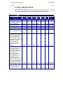
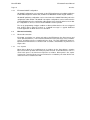
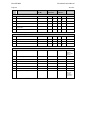
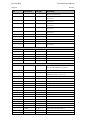
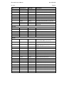
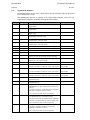
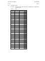
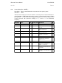
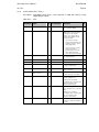
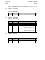
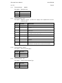
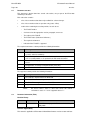
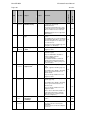
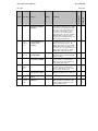
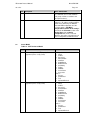
70 SERIES FIRMWARE VERSION
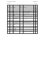
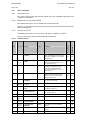
The following table provides the most recent firmware and software versions. For best
results, the Configurator version used should match with the firmware version. A complete
list of firmware and software versions is provided on the 70 Series Utilities CD.
Firmware Versions
Bios
DSP
Host
Config- ICD file Utilities
Version Firmware Firmware urator version
CD
Release
Date
M870 Family
Mx7x Product Release,
New Hardware supported
Dual Bus, Analog I/O
2.1/3.0*
03/24/06
Mx7x Updated Release
2.1/3.0*
"
2.060
2.32
2.44
04/14/06
Mx7x Updated Release
M87x Updated Release
M87x Product Release, Fault
Location, Adjustable Sample
Rate
M87x Product Release; Add
Demand per phase for Watts
,VAr, & VA. Configurator &
BiView improvements w/
modems. Change to Digital
I/O default watchdog contact
(Configurator setup; not
firmware dependent).
Support new version of
hardware on P3x, P4x
modules.
M87x Product Release:
Added 1mHz accuracy on
M87x. Improved poll rate
from 500ms to 100ms for a
single P40 transducer inputs
module (M87x). Fault
distance configuration is
changed. Time sync with
respect to DNP master is
changed from the DNP
master jamming the time to
asking the master what time
to jam. Increased waveform
recording limit from 999 post
trigger for longer recording.
2.1/3.0*
2.1/3.0*
1.240
1.240
2.120
2.150
2.39
2.41
2.50
2.52
10/01/06
12/18/06
3.40
1.30
2.170
2.43
2.56
12/21/07
3.40
1.30
2.18
3.00A
2.57
10/17/08
3.40
1.31
2.19
3.02
2.58
09/30/2009
3.40
1.30
3.01.0
3.01
3.01
1/30/2009
Description
M87x Product Release,
IEC61850 & SNTP; Avg 3Ph Amps and Avg 3-Ph
Volts. MCL file v1.01.
1.210
2.050
2.31
2.43
1.01
Mx7xI/EN M/M
IEC 61850 Protocol Manual
Page 4
70 series
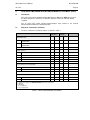
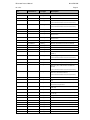
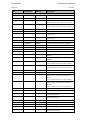
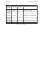
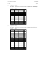
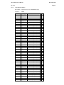
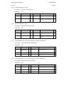
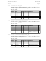
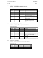
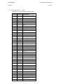
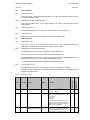
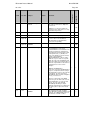
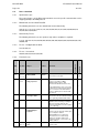
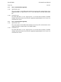
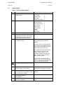
Firmware Versions
Description
M87x Product Release:
Added 1mHz accuracy on
M87x. Improved poll rate
from 500ms to 100ms for a
single P40 transducer inputs
module (M87x). Fault
distance configuration is
changed. Time sync with
respect to DNP master is
changed from the DNP
master jamming the time to
asking the master what time
to jam. Increased waveform
recording limit from 999 post
trigger for longer recording.
M87x Product Release:
Added virtual I/O to DR.
Added Peak Fault Current
Measurement. Improved
password security. Added
support for control
characters for SMS.
Bios
DSP
Host
Config- ICD file Utilities
Version Firmware Firmware urator version
CD
Release
Date
3.40
1.31
3.02
3.02
1.01
3.02
09/30/2009
3.40
1.31
3.04
3.04
1.01
3.04
10/15/2010
3.40
1.32
3.05
3.05
1.02
3.05
2/28/2011
3.40
1.32
3.07
3.07
1.02
3.07
11/11/11
3.40
1.32
3.07.3
3.07
1.02
3.07
2/1/2012
3.40
1.32
3.07.4
3.07
1.02
3.07
2/15/2012
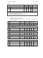
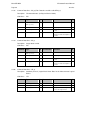
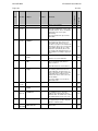
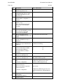
M57x/87x Release:fixes
incorrect error code when
trying to set unsupported
RCB optional fields.
3.40
1.32
3.07.6
3.07
1.02
3.07
3/13/2012
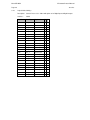
M57x/87x Release:fixed
incorrect neg. error resp. for
test SrvN3 (set mismatching
data types)
3.40
1.32
3.07.7
3.07
1.02
3.07
3/15/2012
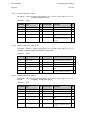
N/A
1.33
4.00.0
4.00
1.03
4.00
11/30/2012
N/A
1.33
4.02.0
4.02
1.04
4.02
4/25/2013
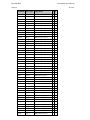
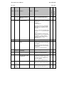
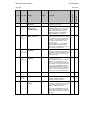
M87x Product Release:
Added support for dual peak
current input range M872
(S16, S17), IEEE C37.232
naming convention, periodic
triggering, and 4 IEC 61850
buffered reports.
M87x Product Release:
Increased pre- and posttrigger time on disturbance
recorders, modified base
memory to 1MB
M87x Product Release:
Fixed FtN1 failure mode.
M87x Product Release:
IED responds with error if
client tries to set qchg bit
M87x Release: support for
H12 & new MMS stack
M87x Production Release:
Deadbands now supported
(Not supported on M57x)
IEC 61850 Protocol Manual
Mx7xI/EN M/M
70 series
Page 5
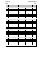
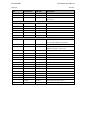
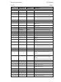
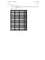
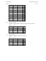
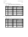
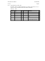
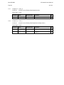
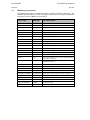
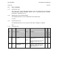
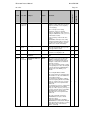
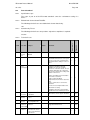
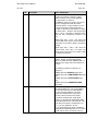
Firmware Versions
Bios
DSP
Host
Config- ICD file Utilities
Description
Version Firmware Firmware urator version
CD
M57x/87x - TrgOps write
w/unsupported bits (Alstom),
N/A
1.33
4.07.0
4.04
1.04
4.04
various fixes
M57x/87x – Change BCR
actVal TYPE to INT32, add
Amp & Vol to TCTR & TVTR,
N/A
1.33
4.08.0
4.05
1.05
4.04
change SPC SBO type to
Release
Date
10/24/13
6/26/14
* H10/H11
70 SERIES MANUAL SET
M87x User Manual
M57x User Manual
70 SERIES Modbus Protocol
70 SERIES DNP3 Protocol
M870D Remote Display Manual
M570Dx Remote Display Manual
®
70 SERIES IEC 61850 Protocol Manual
CERTIFICATION
Alstom Grid certifies that the calibration of our products is based on measurements using
equipment whose calibration is traceable to the United States National Institute of Standards
Technology (NIST).
INSTALLATION AND MAINTENANCE
Alstom Grid products are designed for ease of installation and maintenance. As with any
product of this nature, installation and maintenance can present electrical hazards and
should be performed only by properly trained and qualified personnel. If the equipment is
used in a manner not specified by Alstom Grid, the protection provided by the equipment
may be impaired.
ASSISTANCE
For assistance, contact the Alstom Grid Worldwide Contact Centre:
http://www.alstom.com/grid/contactcentre/
Tel: +44 (0) 1785 250 070
SAFETY SECTION
Please refer to the M87x and M57x User Manuals for information regarding safety,
installation, commissioning and decommissioning.
Mx7xI/EN M/M
IEC 61850 Protocol Manual
Page 6
70 series
COPYRIGHT NOTICE
This manual is copyrighted and all rights are reserved. The distribution and sale of this
manual is intended for the use of the original purchaser or his agents. This document may
not, in whole or part, be copied, photocopied, reproduced, translated or reduced to any
electronic medium or machine-readable form without prior consent of Alstom Grid, except for
use by the original purchaser.
This manual incorporates information protected by copyright and owned by
Bitronics LLC, 261 Brodhead Road, Bethlehem, PA 18017.
Copyright © 2013 Bitronics, LLC. All rights reserved.
The product described by this manual contains hardware and software that is protected by
copyrights owned by one or more of the following entities:
Bitronics LLC, 261 Brodhead Road, Bethlehem, PA 18017;
th
IntervalZero, Inc., 400 Fifth Avenue, 4 Floor, Waltham, MA 02451;
SISCO, Inc., 6605 192 Mile Road, Sterling Heights, MI 48314-1408;
General Software, Inc., Box 2571, Redmond, WA 98073;
Schneider Automation, Inc., One High Street, North Andover, MA 01845;
Triangle MicroWorks, Inc., 2213 Middlefield Court, Raleigh, NC 27615
Greenleaf Software Inc., Brandywine Place, Suite 100, 710 East Park Blvd, Plano, TX 75074
TRADEMARKS
The following are trademarks or registered trademarks of Alstom Grid:
Alstom Grid
the Alstom Grid logo
The following are trademarks or registered trademarks of Bitronics LLC:
The Bitronics logo
Bitronics
The following are trademarks or registered trademarks of the DNP User's Group:
DNP
DNP3
The following are trademarks or registered trademarks of the Electric Power Research
Institute (EPRI):
UCA
The following are trademarks or registered trademarks of Schneider Automation, Inc.:
MODSOFT
PLC
Modicon
Modbus Plus
Modbus
Compact 984
The following are trademarks or registered trademarks of VentureCom, Inc.:
Phar Lap
the Phar Lap logo
The following are trademarks or registered trademarks of Systems Integration Specialists
Company, Inc. (SISCO):
SISCO
MMS-EASE Lite
AX-S4MMS
The following are trademarks or registered trademarks of General Software, Inc.:
General Software
DOS
the GS logo
EMBEDDED BIOS
Embedded
The following are trademarks or registered trademarks of the PCI Industrial Computer
Manufacturers Group:
CompactPCI
PICMG the CompactPCI logo
the PICMG logo
IEC 61850 Protocol Manual
Mx7xI/EN M/M
70 series
Page 7
1.
IEC 61850 IMPLEMENTATION DETAILS
1.1
Introduction
IEC 61850 is the international standard for Ethernet-based communication in substations. It
enables integration of all protection, control, measurement and monitoring functions within a
substation, and additionally provides the means for interlocking and inter-tripping. It
combines the convenience of Ethernet with the security which is essential in substations
today.
Alstom Grid has been involved in the Working Groups which formed the standard, building
on experience gained with UCA2.0, the predecessor of IEC 61850.
The 70 Series measurement IEDs, models M57x and M87x, support the IEC 61850, protocol
over the Ethernet interface. M57x and M87x models are designed to integrate with
substation control systems.
1.2
What is IEC 61850?
IEC 61850 is an international standard, comprised of 14 parts, which defines communication
architecture for electricity utility substations.
The standard defines and offers much more than just a protocol. It provides:
•
Standardized models for IEDs and other equipment within the substation
•
Standardized communication services (the methods used to access and exchange
data)
•
Standardized formats for configuration files
•
Peer-to-peer communication between devices
The standard includes mapping of data onto Ethernet. Using Ethernet in the substation
offers many advantages, but most significantly, including:
1.2.1
•
High-speed data rates (currently 100 Mbits/s, rather than 10’s of kbits/s or less used
by most serial protocols)
•
Multiple masters (called “clients”)
•
Ethernet, as an open standard in every-day use
Interoperability
A major benefit of IEC 61850 is interoperability. IEC 61850 standardizes the data model of
substation IEDs. This responds to the utilities’ desire of having easier integration for different
vendors’ products, i.e. interoperability. It means that data is accessed in the same manner in
different IEDs from either the same or different IED vendors, even though, for example, the
measurement and protection algorithms of different vendors’ IED (or device) types remain
different.
When a device is described as IEC 61850-compliant, this does not mean that it is
interchangeable, but it does mean that it is interoperable. You cannot simply replace one
product with another, however the terminology is pre-defined and anyone with prior
knowledge of IEC 61850 should be able to very quickly integrate a new device without the
need for mapping of all of the new data. IEC 61850 will inevitably bring improved substation
communications and interoperability, at a lower cost to the end user.
Mx7xI/EN M/M
IEC 61850 Protocol Manual
Page 8
1.2.2
70 series
Summary of 70Series IEC 61850 Features (Based on part 7-2 of the IEC 61850 standard)
This table summarizes the IEC 61850 features for M57x or M87x type devices.
Server Model
Section 6
•
3 logical devices – Measurements, Records, System
•
1 File Directory (of COMTRADE files)
Association
•
Two Party Application Association Model – used for normal data and (non GOOSE) reporting. Includes a simple method to inhibit writing for view-only
applications
•
Multicast Association Model – used for GOOSE messaging
Section 7
Logical Device
Section 8
Mx7x Measurement IEDs
Logical Nodes
•
50+ Logical Nodes as defined in the Model Implementation Conformance
Statement (MICS). Exact Count is dependent upon device configuration (for
example, number of physical I/O points, which can vary based on the
installed options )
•
No pre-defined datasets
•
32 pre-defined URCBs (Unbuffered Report Control Blocks) in System/LLN0
•
4 pre-defined BCRBs (Buffered Report Control Blocks) in System/LLN0
•
8 pre-defined GoCB (GOOSE Control Blocks) in System/LLN0
Section 9
Data
Section 10
•
Includes all features except access controls (however, the ability to write to
points depends upon association parameters)
Datasets
Section 11
•
26 definable datasets with FCD/FCDA capability. (A dataset consists of a
named list of variables)
Substitution
Section 12
NOT SUPPORTED in 70 Series
Settings Groups
Section 13
NOT SUPPORTED in 70 Series
Report Control Blocks (and Reports)
•
32 indexed UCRBs (Unbuffered Report Control Blocks)
•
Power-on configurability includes cbName (control block name) and DatSet
(dataset).
•
Dynamic configurability includes RptID (report ID), OptFlds (option fields),
BufTm (buffer time), and TrgOps (trigger options).
•
4 indexed BRCB (Buffered Report Control Blocks).
•
LCBs (Logic Control Blocks) are UNSUPPORTED
•
Dynamic RCBs (Report Control Blocks) are UNSUPPORTED. (New RCBs
cannot be created after power-on once the configuration reboot occurs to
accept the 61850 configuration).
Section 14
IEC 61850 Protocol Manual
Mx7xI/EN M/M
70 series
Page 9
Generic Substation Events – GSE ( and GOOSE)
Section 15
•
8 publishing GOOSEs (with GOOSE Control Block - GoCB)
•
Power-on configurability includes Control Block name (cbName), Dataset
(DatSet), Application ID (AppID), Configuration Revision (confRev) and
Dataset Address (DstAddress).
•
No Dynamic Configurability - only Report Enable (rptEna) can be changed.
•
32 subscribing GOOSEs, with 32 booleans and 32 integers/ enumerations
and 32 floating points (analogues) populated in the internal 70Series
database.
•
No GOOSE management capabilities (these are GetGoReference and
GetGOOSEElement).
Sampled Measured Values
Section 16
NOT SUPPORTED in 70Series
Controls – Control Models
Section 17
•
Time Activated Operate (TAO) which is “perform operation at a later time” is
NOT SUPPORTED.
•
Operate-many configuration is supported, but can only be set up through the
70Series Configurator software tool used to set UCA configuration, not in the
61850 IED Configurator software tool.
•
Pulse time configuration is supported, but can only be setup through the
70Series Configurator software tool used to set UCA configuration, not in the
61850 IED Configurator software tool.
•
The following physical inputs are supported – status-only, direct-with-normalsecurity, sbo-with-normal security (including cancel).
•
For internal control points (other than Digital outputs), only direct-withnormal-security is supported.
•
Many controls are status-only (such as Mod.ctl.Val)
Time Synchronization
Section 18
•
Up to 2 SNTP servers using optional many-cast (or any-cast) mode of
operation are supported along with configurable polling times. SNTP servers
can be polled for configurable time, but only one at a time.
Files
Section 20
•
COMTRADE files are supported.
Mx7xI/EN M/M
IEC 61850 Protocol Manual
Page 10
1.2.3
70 series
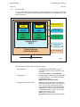
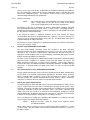
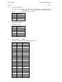
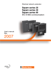
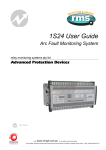
The data model
To ease understanding, the data model of any IEC 61850 IED can be viewed as a hierarchy
of information. The categories and naming of this information is standardized in the IEC
61850 specification.
Data Attribute
stVal
Mag
SPCSO
TotW
Data Object
LN1
(GGIO)
LN2
(MMXU)
Logical Node
Logical Device
(IED1)
(1 to n)
Logical Device
(1 to n)
Physical Device
(network address)
Physical Device
M0183ENa
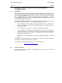
FIGURE 1 - DATA MODEL LAYERS IN IEC 61850
The levels of this hierarchy can be described as follows:
- Physical Device
-
Identifies the actual IED within a system.
Typically the device’s name or IP address can
be used.
(for example Feeder_1 or 192.168.0.254).
- Logical Device
-
Identifies groups of related Logical Nodes within
the Physical Device. For the 70Series IEDs 3
Logical Devices exist:
Measurements, Records, System.
- Wrapper/Logical Node Instance
-
Identifies the major functional areas within the
IEC 61850 data model. Either 3 or 6 characters
are used as a prefix to define the functional
group (wrapper) while the actual functionality is
identified by a 4 character Logical Node name
suffixed by an instance number. For example,
GGIO1 (generic process I/O),
MMXU1(measurements Bus 1),
DmdMMXU1(Present thermal demands for Bus
1).
IEC 61850 Protocol Manual
Mx7xI/EN M/M
70 series
1.3
Page 11
- Data Object
-
This next layer is used to identify the type of
data you will be presented with. For example,
SPCSO1 (Digital output 1) of Logical Node type
GGIO.
- Data Attribute
-
This is the actual data (measurement value,
status, description, etc.). For example, stVal
(status value) indicating actual position of the
output contact for Digital output 1 for Data
Object type SPCSO1 of Logical Node type
GGIO.
IEC 61850 in the Mx70 series IEDs
IEC 61850 can be implemented in the 70 series of IEDs (M57x, M87x) only when equipped
with an Ethernet option. The M87x requires an Ethernet module that is capable of
supporting a 100Mb connection. For an M57x it is necessary that the instrument be
equipped with a factory installed Ethernet option. The appropriate version of Host firmware
and hardware defined below for 70Series devices is necessary to support the IEC 61850
protocol implementation and is required for proper operation. The 70 Series Configurator
software and the IEC 61850 IED Configurator software (Micom S1 Support Software)
provide the Configuration tools, which manage the majority of the IEC 61850 implementation
and data transfer capabilities. An MMS browser is used to view the data.
For M57x and M87x devices to be used with the IEC 61850 communication protocol, here
are some essential requirements that need to be met for these Mx70 devices to properly
operate, namely:
•
the Host board must have been manufactured with 64M RAM,
•
It is necessary that the Host board has a compact Flash card installed
•
The Host firmware version must be version v3.00.0 (or later) which is the version that
implements the IEC 61850 communications protocol.
•
The 70Series Configurator software must be the proper version in order to support:
Creation of new initialization (INI) files: The INI files are required in order to
configure the Mx70 device. The 70 Series Configurator creates these INI files
and stores them on the Mx70 device in the folder “C:\Config”.
Creation of the IED Capability Description (ICD) file: The 70 Series ICD file is
an IEC 61850 Substation Configuration Language (SCL) file which contains
the IEC 61850 'capability' description of the particular 70 Series IED. It is
created by the 70 Series Configurator tool and then used by the IEC 61850
IED Configurator tool to perform an IEC 61850 configuration. After a new
device configuration is created, the 70 Series Configurator tool automatically
installs the ICD file in the "C:\Config" folder on the Mx70 device. In addition,
the 70 Series Configurator places a second copy of the ICD file in a userdefinable location on the local personal computer (PC) for use by the IEC
61850 IED Configurator tool. This user-definable location can be set using
the "File->Set Templates directory" option in the 70 Series Configurator tool
menu. It is recommended this option be set to the location of the "Templates"
folder used by the IEC 61850 IED Configurator tool (i.e. "..\IED
Configurator\Templates"). If necessary, the 70 Series Configurator tool will
automatically create two sub-folders named "M57X" and "M87X" where it will
place the ICD files specific to each of the M57x and M87x family of devices,
respectively.
Creation of the MiCOM Configuration Language (MCL) file: The 70 Series
MCL file, which contains the IEC 61850-specific configuration of the device, is
a binary file created by the IEC 61850 IED Configurator tool. This tool uses
the ICD file as a template from which it can create an IEC 61850 device
configuration. After configuration is completed and verified, the user can
select "Device->Send Configuration" (CTRL+D) menu option to upload the
Mx7xI/EN M/M
IEC 61850 Protocol Manual
Page 12
70 series
configuration to the device. The user will then be asked to enter the IP
address of the device. Two configurations are supported; 'active' and
'inactive'. The program will then prompt the user if they would like the current
configuration to be made the active configuration. The two configurations
correspond to the following filenames;
•
Active configuration filename - IEC61850_CONFIG.MCL
•
Inactive configuration filename - IEC61850_CONFIG.MC2
Finally, the user will be prompted if they would like the Mx70 IED to be
automatically restarted. The user should answer 'yes' in order for the active
bank switch to take effect during the next power cycle.
The user should also make a backup copy of their configuration. This
can be done using the "File-Save" or "File->Save As" menu options
which saves a backup copy of the MCL file to the local PC. It should
be noted that in addition to creating 'new' IEC 61850 configurations
using ICD template files, the IED Configurator tool gives the user the
ability to import and export the following types of IEC 61850 SCL
files;
•
•
Importing Substation Configuration Description files (SCD)
Configured IED Description files (CID)
Individual IED Description files (IID)
Exporting Configured IED Description files (CID)
Individual IED Description files (IID)
IED Configuration Description files (ICD)
Substation Configuration Description files (SCD)
Extensible Markup Language files (XML)
In order to communicate with an IEC 61850 device, it is necessary to set its Ethernet IP
address. Before configuring an Mx70 device on the TCP/IP network you will need to
determine the IP address for the device. An IP address is needed to enter a configuration
for an Mx70 device, using the 70Series Configurator and the IEC 61850 IED Configurator
software tools. The IP address can be retrieved or changed though the P1 service port
(serial port) by establishing a connection through Hyperterminal. (Refer to the relevant Host
section in either the M87x or M57x user manual if you need to acquaint yourself with the
connection to and operation over the service port P1.) It is recommended that before
establishing a TCP/IP connection that the IP address be changed from the factory default
address of 192.168.0.254 to the IP address to be assigned for the IED.
A serial connection to the Mx70 device’s P1 service port can be used to obtain the IP
address from an Mx70 device. The service port operating with Hyperterminal allows the IP
address to be retrieved and changed by typing the “ip” command. You are prompted to enter
a new IP address.
During the configuration process you will enter the device’s IP address. The IP address is
entered starting with the 70Series Configurator while in the Identity menu page. On the
Identity menu page, a radio button allows the user to select the source from which the IP
address (and SNTP addressing) will be loaded. The IP address can be obtained by either
loading it from the INI file or the MCL file.
If any change is made to the IP address by way
of the “IEC 61850 IED Configurator”, the IP address may not be written to the Mx70 device’s
IDENTITY INI file. As a result, it is possible that the 70Series Configurator Identity page may
not indicate the actual IP address. It is always a good practice to determine the IP address
before the configuration process is initiated.
IEC 61850 Protocol Manual
70 series
Mx7xI/EN M/M
Page 13
In order to communicate with an IEC 61850 device, it is necessary to know its Ethernet
address. This IP address can then be configured into either:
1.3.1
•
An IEC 61850 “client” (or master). For example a computer or Human Machine
Interface (HMI).
•
An “MMS browser”, with which the full data model can be retrieved from the IED.
Note that an MMS browser, such as SISCO’s MMS Object Explorer, may be required
in order to browse and verify IEC 61850 objects that have been configured for the
Mx70 device.
Capability
The IEC 61850 interface provides the following capabilities:
1.
Read access to measurements
All measurands are presented using the measurement Logical Nodes, in the
‘Measurements’ Logical Device. Reported measurement values are refreshed by the
IED once per second, in line with the IEDs user interface
2.
Generation of unbuffered reports on change of status/measurement
Through the 61850 client, reports are enabled when the RptEna bit is set to a value of
1 in the Unbuffered and Buffered Report Control Blocks (URCB and BRCB). When
reports are enabled, any change of state in statuses and/or measurements (which
includes ‘measurements’ and such number-of-COMTRADE files, for example
“Records/WrxRDRE1$ST$FltNum$stVal”, where the fault number indicates the
COMTRADE file count; the COMTRADE file count is the next number to be assigned)
are reported to the client. However, changes to floating-point values cannot trigger a
report, but will nonetheless always be included in a report. Since Integer values have
an implied deadband of 1, integer values will only be reported if there is a change in
value. Unbuffered and Buffered Report Control Blocks (URCB and BRCB) can be
configured in Mx70 devices by using the “IEC 61850 Configurator” tool, however the
client must set the RptEna to 1 in order to enable a report to be sent to the client. For
the purpose of viewing the contents of reports, an MMS browser can be used as the
client performing that purpose. If using a browser such as SISCO's MMS Object
Explorer, a Report Control Block (RCB) can be enabled by right clicking on the RCB
(such as urcb01), selecting "Monitor Reports", then clicking on the RCB (such as
urcb01) and selecting "Enable Reports.
3.
Support for time synchronization over an Ethernet link
Time synchronization is supported using SNTP (Simple Network Time Protocol); this
protocol is used to synchronize the internal real time clock in substation devices, (i.e.,
control systems, relays, IEDs). It is recommended that only one method of time
synchronization be used for an Mx70 device. Time synchronization issues may be
encountered if an Mx70 device operates with multiple clients that are operating from
multiple protocols, which rely upon time synchronization from different time sources.
The order of priority for time synchronization methods used in Mx70 devices is that
IRIG-B time will take priority over UCA time, which will take priority over SNTP time.
This allows a more accurate time source to be the over-riding time synchronization
source for the Mx70 device.
Use care when selecting a method for time synchronization with 70Series devices
when IEC 61850 protocol and DNP protocol co-exist on the same IED device: In this
case, do NOT use the DNP time set command with SNTP (or any of the other time
synchronization methods). A DNP set time command will override all other methods
of time synchronization, which may result in a time contention between the 2 time
sources, where one and then the other will set the time and time may never be able to
synchronize correctly.
4.
GOOSE peer-to-peer communication
GOOSE communications of statuses are included as part of the IEC 61850 protocol
implementation. For more details see the section covering Peer-to-peer (GSE)
Mx7xI/EN M/M
IEC 61850 Protocol Manual
Page 14
70 series
communications.
IEC 61850 Protocol Manual
Mx7xI/EN M/M
70 series
Page 15
5.
Disturbance record extraction
Extraction of disturbance records, by file transfer, is supported. Available for
extraction are the records created from the 2 Disturbance recorders and the 2
Waveform recorders in the Mx70 device. The record is extracted as an ASCII format
COMTRADE file.
Setting changes are not supported in the current IEC 61850 implementation. In order to
keep this process as simple as possible, such setting changes would be done using the
70Series Configurator and the “IEC 61850 IED Configurator” (MiCOM S1 support software)
over the Ethernet link. A reboot of the device is necessary for the configuration to take effect
after changing any of the configurable parameters for an Mx70 device.
1.3.2
IEC 61850 Configuration
One of the main objectives of IEC 61850 is to allow IEDs to be directly configured from a
configuration file generated at system configuration time. At the system configuration level,
the capabilities of the IED are determined from an IED capability description (ICD) file. For
Mx70 devices, the ICD file is an output file generated by the 70 Series Configurator software
tool. The ICD file is automatically stored in the “C:\Config” folder on the Mx70 device. In
order to perform the IEC 61850 configuration of an Mx70 device, it is necessary to load the
ICD file that is stored on the Mx70 device onto the hard drive of the computer on which the
configuration tools were installed. It is recommended that the ICD file be stored on the user
PC’s hard drive under the Programs folder where the IEC 61850 IED Configurator program
is installed. A sub folder named “Templates” contains subfolders for M57x and M87x
devices. If these subfolders do not exist it would be necessary to create them. The “61850
IED Configurator” software requires that the ICD file be loaded as an input file in order to
complete the IEC 61850 configuration Note that the 70Series Configurator should be able to
automatically make and store the icd file on the PC for the user. The location where the ICD
file should be stored is iedcfg\Templates and the M57x and/or M87x folders should
automatically created when the user sets iedcfg\Templates location as the desired location
where the ICD file is saved. The browse function can be used from within the IED
Configurator to make it easier to load the ICD file once it has been saved on the PC The
61850 IED Configurator will produce the Micom Configuration Language (MCL) file which
contains the IEC 61850 configuration that is loaded into the Mx70 device.
Using a collection of these ICD files from varying products, the entire protection and
measurement function of a substation can be designed, configured and tested (using
simulation tools) before the product is even installed into the substation.
To aid in this process, the 61850 IED Configurator software tool (included on the CD as
MiCOM S1 Studio Support Software) allows the pre-configured IEC 61850 configuration file
(an SCD file or CID file) to be imported and transferred to the IED. Alongside this, the
requirements of entering a configuration manually are satisfied by allowing the manual
creation of configuration files for M57x and M87x devices based on their original IED
capability description (ICD) file.
Other features include the extraction of configuration data for viewing and editing, and a
sophisticated error checking sequence which ensures that the configuration data is valid for
sending to the IED and that the IED will function within the context of the substation.
1.3.2.1
Configuration Banks
To promote version management and minimize down-time during system upgrades and
maintenance, the Mx70 devices utilize a storage mechanism consisting of multiple
configuration banks. These configuration banks are categorized as:
•
Active Configuration Bank (MCL file stored in E:\Config on Mx70 device
•
Inactive Configuration Bank (MC2 file is previous configuration file stored in E:\Config
on Mx70 device)
Any new configuration to the Mx70 device will be automatically stored into the inactive
configuration bank, therefore not immediately affecting the current configuration
When the upgrade or maintenance stage is complete, the 61850 IED Configurator tool will
prompt the user to make the configuration (to a single IED) active. A reboot of the Mx70
Mx7xI/EN M/M
IEC 61850 Protocol Manual
Page 16
70 series
device is necessary in order for the configuration to be activated, authorizing the activation of
the new configuration contained in the inactive configuration bank, by switching the active
and inactive configuration banks. This technique ensures that the system down-time is
minimized while enabling the new configuration.
1.3.2.2
Network connectivity
NOTE:
This section presumes a prior knowledge of IP addressing and related
topics. Further details on this topic may be found on the Internet
(search for IP Configuration) and in numerous relevant books.
Configuration of the relay IP parameters (IP Address, Subnet Mask, Gateway) and SNTP
time synchronization parameters (SNTP Server 1, SNTP Server 2, and polling interval) is
performed by the IED Configurator tool, so if these parameters are not available via an SCL
file, they must be configured manually.
If the assigned IP address is duplicated elsewhere on the same network, the remote
communications will operate in an indeterminate way. However, a check is performed for a
conflict on every IP configuration change and at power up. The Mx70 allows other devices
to perform duplicate IP address detection.
An Mx70 device can be configured to accept data from networks other than the local network
by using the ‘Gateway’ setting.
1.4
The data model of Mx70 Measurement IEDs
The data model naming convention, which was adopted in the M57x and M87x
Measurement IEDs, has been standardized for consistency. Hence the Logical Nodes are
allocated to one of the three Logical Devices, Measurements, Records, or System as
appropriate, and the wrapper names used to instantiate Logical Nodes will remain consistent
between the M57x and M87x measuring IEDs
The data model is described in the Model Implementation Conformance Statement (MICS)
document, which is available as a separate section of this IEC 61850 user manual. The
MICS document provides lists of Logical Device definitions, Logical Node definitions,
Common Data Class and Attribute definitions, Enumeration definitions, and MMS data type
conversions. It generally follows the format used in Parts 7-3 and 7-4 of the IEC 61850
standard.
1.5
The communication services of Mx70 Measurement IEDs
The IEC 61850 communication services which are implemented in the M57x and M87x IEDs
are described in the Protocol Implementation Conformance Statement (PICS) document,
which is available within a separate section of this IEC 61850 user manual. The PICS
document provides the Abstract Communication Service Interface (ACSI) conformance
statements as defined in Annex A of Part 7-2 of the IEC 61850 standard.
1.6
Peer-to-peer (GSE) communications
The implementation of IEC 61850 with respect to Generic Substation Events (GSE) sets the
way for cheaper and faster inter-device communications amongst control systems, relays
and IEDs. The generic substation event model provides the possibility for a fast and reliable
system-wide distribution of input and output data values. The generic substation event
model is based on the concept of an autonomous decentralization, providing an efficient
method allowing the simultaneous delivery of the same generic substation event information
to more than one physical device through the use of multicast services.
The use of multicast messaging means that IEC 61850 GOOSE uses a publisher-subscriber
system to transfer information around the network*.
NOTE: *
Multicast messages cannot be routed across networks without
specialized equipment.
When a device detects a change in one of its monitored status points it publishes (i.e. sends)
a new message. Any device that is interested in the information subscribes (i.e. listens) to
the data it contains.
IEC 61850 Protocol Manual
70 series
Mx7xI/EN M/M
Page 17
Each new message is re-transmitted at user-configurable intervals until the maximum
interval is reached, in order to overcome possible corruption due to interference, and
congestion.
1.6.1
Scope (GOOSE messages)
In the Mx70 device database, a maximum of 32 GOOSE binary inputs, 32 GOOSE integer
inputs, and 32 GOOSE float (floating point) inputs are available to be mapped directly up to a
published dataset in a GOOSE message. All Mx70 published GOOSE signals may contain
BOOLEAN, Integer, and Float values. These signals are referred to by the following names:
•
GOOSE Binary Input - Ind#, where # will be a number between 1-32,
•
GOOSE Integer Input - IntIn#, where # will be a number between 1-32,
•
GOOSE Analogue Input - AnIn# (floating point), where # will be a number between 132,
These inputs for a GOOSE message would be mapped in the IEC 61850 IED Configurator.
The 61850 IED Configurator tool is used to configure GOOSE publishing and GOOSE
subscribing. It is only possible to publish a GOOSE from System/LLN0.in the “IEC 61850
IED Configurator”. To subscribe to a GOOSE, use System/GosGGIO1 to configure the
GOOSE form the “IEC 61850 IED Configurator” tool.
Each GOOSE signal contained in a subscribed GOOSE message can be mapped to any of
the 32 GOOSE binary inputs, 32 GOOSE integer inputs, and 32 GOOSE float inputs. These
virtual inputs used by the GOOSE message allow the mapping to internal logic functions for
protection control, directly to output contacts, or to LEDs for monitoring.
Once the binary, integer, and analogue points are mapped in a particular application a
GOOSE message should be usable in order to cause trigger conditions for other devices
(e.g cross triggering between Mx70 devices), where a 2nd IED is configured by
programming a trigger condition expected to be contained in the dataset received in a
GOOSE message. When the trigger occurs (such as a binary state change) a GOOSE
nd
message results, containing a dataset that can be mapped to the 2 IEDs GOOSE inputs
(either the binary inputs, integer inputs, or analogue floating point inputs) and used to trigger
that IED on the network, based on the values or measurements contained in the dataset
The Mx70 IEDs can subscribe to all GOOSE messages but only the following data types can
be decoded and mapped to the inputs (binary, integer, and float) supported by the GOOSE.
•
BOOLEAN
•
BSTR2
•
INT16
•
INT32
•
INT8
•
INT16U
•
INT32U
•
INT8U
•
FLOAT32
•
SPS
•
DPS
Mx7xI/EN M/M
Page 18
1.6.2
IEC 61850 Protocol Manual
70 series
IEC 61850 GOOSE configuration
All GOOSE configurations are performed via the IED Configurator tool available within the
61850 IED Configurator software tool (available from MiCOM S1 Studio Support Software).
All GOOSE publishing configuration can be found under the ‘GOOSE Publishing’ tab in the
configuration editor window. All GOOSE subscription configurations can be found under the
‘External Binding’ tab in the configuration editor window. Care should be taken to ensure that
the configuration is correct, to ensure efficient GOOSE scheme operation.
The set up (programming of trigger conditions to allow an Mx70 device to be cross triggered
from another device’s dataset received as a GOOSE message is a typical distributed
recorder application for Mx70 devices in a substation.
1.7
Ethernet functionality
1.7.1
Ethernet disconnection
IEC 61850 ‘associations’ are unique and made to the IED between the client (master) and
server (IEC 61850 device). In the event that the Ethernet is disconnected, such associations
are lost, and will need to be re-established by the client. The TCP_KEEPALIVE function is
implemented in Mx70 devices to monitor each association, and terminate any which are no
longer active.
1.7.2
Loss of power
Mx70 devices allow the re-establishment of associations by the client without a negative
impact on the IED’s operation after having its power removed. As the Mx70 device acts as a
server in this process, the client must request the association. When power is lost, reports
requested by connected clients are reset and must be re-enabled by the client when it next
creates the new association to the IED.
IEC 61850 Protocol Manual
Mx7xI/EN M/M
70 series
Page 19
2.
PROTOCOL IMPLEMENTATION CONFORMANCE STATEMENT (PICS)
2.1
Introduction
This section is the Protocol Implementation Conformance Statement (PICS) and presents
the ACSI conformance statements as defined in Annex A of Part 7-2 of the IEC 61850
standard.
The 70 Series IEC 61850 standard implementation shall conform to the Protocol
Implementation Conformance Statement below:
2.2
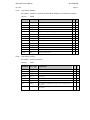
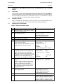
ACSI basic conformance statement
The basic conformance statement shall be as defined in Table 1.
Client/
Subscriber
Server/
Publisher
Client-Server roles
B11
Server side (of TWO-PARTY-APPLICATIONASSOCIATION)
c1
Y
B12
Client side of (TWO-PARTY-APPLICATIONASSOCIATION)
c1
N
SCSMs supported
B21
SCSM: IEC 61850-8-1 used
B22
SCSM: IEC 61850-9-1 used
B23
SCSM: IEC 61850-9-2 used
N
B24
SCSM: other
N
N
Y
N
Generic substation event model (GSE)
B31
Publisher side
O
Y
B32
Subscriber side
O
Y
Transmission of sampled value model (SVC)
B41
Publisher side
O
N
B42
Subscriber side
O
N
c1 – shall be ‘M’ if support for LOGICAL-DEVICE model has been declared.
O – Optional
M – Mandatory
Y – Yes (supported)
N – No (not supported)
TABLE 1 - BASIC CONFORMANCE STATEMENT
Value/Comments
Mx7xI/EN M/M
IEC 61850 Protocol Manual
Page 20
2.3
70 series
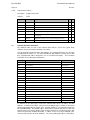
ACSI models conformance statement
The ACSI models conformance statement shall be as defined in Table 2.
Client/
Subscriber
Server/
Publisher
If Server side (B1) supported
M1
Logical device
c2
N
c2
Y
M2
Logical node
c3
N
c3
Y
M3
Data
c4
N
c4
Y
M4
Data set
c5
N
c5
Y
M5
Substitution
O
N
O
N
M6
Setting group control
O
N
O
N
O
N
O
Y
Reporting
M7
Buffered report control
M7-1
sequence-number
M7-2
report-time-stamp
Y
M7-3
reason-for-inclusion
Y
M7-4
data-set-name
Y
M7-5
data-reference
Y
M7-6
buffer-overflow
Y
M7-7
entryID
Y
M7-8
BufTim
Y
M7-9
IntgPd
Y
M7-10
GI
Y
M7-11
conf-revision (revision 2 adds this row entry)
M8
Unbuffered report control
Y
O
N
O
Y
M8-1
sequence-number
Y
M8-2
report-time-stamp
Y
M8-3
reason-for-inclusion
Y
M8-4
data-set-name
Y
M8-5
data-reference
Y
M8-6
BufTim
Y
M8-7
IntgPd
Y
M8-8
GI
Y
M8-9
conf-revision (revision 2 adds this row entry)
Logging
M9
Log control
M9-1
M10
M11
O
N
O
N
O
N
O
N
IntgPd
Log
Control
N
N
O
N
O
N
M
N
M
Y
O
Y
O
Y
If GSE (B31/32) is supported
M12
M12-1
M12-2
M13
GOOSE
entryID (revision 2 removes this row entry)
N
DataRefInc (revison 2 removes this row entry)
GSSE
If SVC (B41/42) is supported
N
O
Y
O
Y
Value/Comments
IEC 61850 Protocol Manual
Mx7xI/EN M/M
70 series
Page 21
Client/
Subscriber
Server/
Publisher
M14
Multicast SVC
O
N
O
N
M15
Unicast SVC
O
N
O
N
M16
Time
M
Y
M
N
M17
File Transfer
O
N
O
Y
Value/Comments
Time source with
required accuracy
shall be available
c2 – shall be ‘M’ if support for LOGICAL-NODE model has been declared
c3 – shall be ‘M’ if support for DATA model has been declared
c4 – shall be ‘M’ if support for DATA-SET, Substitution, Report, Log Control, or Time model has been declared
c5 – shall be ‘M’ if support for Report, GSE, or SMV models has been declared
TABLE 2 - ACSI MODELS CONFORMANCE STATEMENT
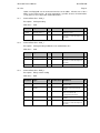
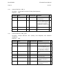
2.4
ACSI service conformance statement
The ACSI service conformance statement shall be as defined in Table 3. (Depending on the
statements in Table 1).
Services
AA:
TP/MC
Client/
Subscriber
Server/
Publisher
Server (clause 6)
S1
ServerDirectory
TP
N
M
Y
Application association (clause 7)
S2
Associate
M
N
M
Y
S3
Abort
M
N
M
Y
S4
Release
M
N
M
Y
TP
M
N
M
Y
Logical device (clause 8)
S5
LogicalDeviceDirectory
Logical node (clause 9)
S6
LogicalNodeDirectory
TP
M
N
M
Y
S7
GetAllDataValues
TP
O
N
M
Y
Data (clause 10)
S8
GetDataValues
TP
M
N
M
Y
S9
SetDataValues
TP
O
N
O
Y
S10
GetDataDirectory
TP
O
N
M
Y
S11
GetDataDefinition
TP
O
N
M
Y
Comments
Mx7xI/EN M/M
IEC 61850 Protocol Manual
Page 22
70 series
Services
AA:
TP/MC
Client/
Subscriber
Server/
Publisher
Data set (clause 11)
S12
GetDataSetValues
TP
o
N
M
Y
S13
SetDataSetValues
TP
O
N
o
N
S14
CreateDataSet
TP
O
N
o
N
S15
DeleteDataSet
TP
O
N
o
N
S16
GetDataSetDirectory
TP
O
N
o
Y
TP
M
N
M
N
N
O
N
N
Substitution (clause 12)
S17
SetDataValues
Setting group control (clause 13)
S18
SelectActiveSG
TP
O
S19
SelectEditSG
TP
O
N
O
S20
SetSGValues
TP
O
N
O
N
S21
ConfirmEditSGValues
TP
O
N
O
N
S22
GetSGValues
TP
O
N
O
N
S23
GetSGCBValues
TP
O
N
O
N
TP
c6
N
c6
Y
Reporting (clause 14)
Buffered report control block (BRCB)
S24
Report
S24-1
data-change (dchg)
Y
S24-2
qchg-change (qchg)
N
S24-3
data-update (dupd)
N
S25
GetBRCBValues
TP
c6
N
c6
Y
S26
SetBRCBValues
TP
c6
N
c6
Y
TP
c6
N
c6
Y
Unbuffered report control block (URCB)
S27
Report
S27-1
data-change (dchg)
N
Y
S27-2
qchg-change (qchg)
N
N
S27-3
data-update (dup)
N
N
S28
GetURCBValues
TP
c6
N
c6
Y
S29
SetURCBValues
TP
c6
N
c6
Y
c6 – shall declare support for at least one (BRCB or URCB)
Comments
IEC 61850 Protocol Manual
Mx7xI/EN M/M
70 series
Page 23
Services
AA:
TP/MC
Client/
Subscriber
Server/
Publisher
Logging (clause 14)
Log control block
S30
GetLCBValues
TP
M
N
M
N
S31
SetLCBValues
TP
O
N
M
N
S32
QueryLogByTime
TP
c7
N
M
N
S33
QueryLogAfter
TP
c7
N
M
N
S34
GetLogStatusValues
TP
M
N
M
N
Log
c7 – shall declare support for at least one (QueryLogByTime or QueryLogByEntry)
Generic substation event model (GSE) (clause 14.3.5.3.4)
GOOSE-CONTROL-BLOCK
S35
SendGOOSEMessage
MC
c8
N
c8
Y
S36
GetGoReference
TP
O
N
c9
N
S37
GetGOOSEElementNumber
TP
O
N
c9
N
S38
GetGoCBValues
TP
O
N
O
Y
S39
SetGoCBValues
TP
O
N
O
Y
N
c8
Y
N
c9
N
N
c9
N
N
O
N
N
O
N
N
c10
N
N
GSSE-CONTROL-BLOCK
S40
SendGSSEMessage
MC
c8
S41
GetGsReference
TP
O
S42
GetGSSEElementNumber
TP
O
S43
GetGsCBValues
TP
O
S44
SetGsCBValues
TP
O
c8 – shall declare support for at least one (SendGOOSEMessage or SendGSSEMessage)
c9 – shall declare support if TP association is available
Transmission of sampled value model (SVC) (clause 16)
Multicast SVC
S45
SendMSVMessage
MC
c10
S46
GetMSVCBValues
TP
O
N
O
S47
SetMSVCBValues
TP
O
N
O
N
Unicast SVC
S48
SendUSVMessage
TP
c10
N
c10
N
S49
GetUSVCBValues
TP
O
N
O
N
S50
SetUSVCBValues
TP
O
N
O
N
c10 – shall declare support for at least one (SendMSVMessage or SendUSVMessage)
Comments
Mx7xI/EN M/M
IEC 61850 Protocol Manual
Page 24
70 series
Services
AA:
TP/MC
Client/
Subscriber
Server/
Publisher
N
O
Y
N
O
N
N
O
Y
Y
Comments
Control (clause 17.5.1)
S51
Select
TP
M
S52
SelectWithValue
TP
M
S53
Cancel
TP
O
S54
Operate
TP
M
N
M
S55
CommandTermination
TP
M
N
O
N
S56
TimeActivated-Operate
TP
O
N
O
N
File transfer (clause 20)
S57
GetFile
TP
o
N
M
Y
S58
SetFile
TP
O
N
O
N
S59
DeleteFile
TP
O
N
O
N
S60
GetFileAttributeValues
TP
O
N
M
Y
Time (5.5)
T1
Time resolution of internal clock
T2
Time accuracy of internal clock
20 (1µs)
nearest
negative
power of 2 in
seconds
T0
T1
14 (100µs)
T2
T3
T4
T5
T3
supported TimeStamp resolution
-
20 (1µs)
TABLE 3 - ACSI SERVICE CONFORMANCE STATEMENT
Nearest value
of 2**-n in
seconds
according to
5.5.3.7.3.3
IEC 61850 Protocol Manual
Mx7xI/EN M/M
70 series
Page 25
3.
MODEL IMPLEMENTATION CONFORMANCE STATEMENT (MICS)
3.1
Introduction
This specification is the Model Implementation Conformance Statement (MICS) and presents
the top-level IEC 61850 data model that has been implemented. The definitions of all used
Logical Nodes and their associated Common Data Classes, components and associated
enumerated values are also included for completeness.
The reader is expected to be conversant with the terminology presented within the IEC
61850 part 7 series of specifications.
3.2
Objective
To provide comprehensive details of the standard data object model elements supported by
each one of the logical devices - M571, M572 (Dual Feeder), M572 (Breaker & ½), M871,
M872 (Dual Feeder), and M872 (Breaker & ½.). The MICS is conformant to the devices
associated ICD (Substation Configuration Language) file, according to part 6 of the IEC
61850 standards. The layout of the presented tables within this document is conformant to
the Part 7 series of the IEC 61850 standard specifications with the following exceptions:
3.3
•
The "Trigger Options" field is not presented within the data object tables.
•
The "M/O" (Mandatory/Optional) field is not present in the data object tables, as the
definitions are as deployed within the models
•
An additional column "X" is used to signify Alstom Grid custom objects or attributes
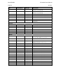
Logical Device definitions
The Mx7x IEDs implement an IEC 61850 server that can contain one or more Logical
Devices. Each Logical Device contains a data model built from instances of specific Logical
Nodes and must consist of at least an instance of the LPHD Logical Node (which is
responsible for providing physical device information) and an instance of the LLN0 Logical
Node (for addressing common issues across the Logical Device).
The IEC 61850 data model is contained within the Logical Devices detailed in the table
below. All Mx7x devices will name the supported Logical Devices consistently to ensure that
data model variables with the same purpose will have the same name within each Mx7x
server.
Logical Device
Comment/Usage
Control
This Domain is not used in any of the Mx70 Logical Devices
Measurements
Mx70 Series Measurements Domains: Measurement Domains are used for each
Measurements Logical Devices. The following list indicates the 6 types of 70 Series
Measurements Logical devices possible:
M571, M572 Dual Feeder, M572 Breaker & ½
M871, M872 Dual Feeder, M872 Breaker & ½
Protection
This Domain is not used in any of the Mx70 Logical Devices
Records
Mx70 Series Record Domain for the Measurements Logical Devices:
M571, M572 Dual Feeder, M572 Breaker & ½
M871, M872 Dual Feeder, M872 Breaker & ½
System
Mx70 Series System Domains for the Measurement Logical Devices:
M571, M572 Dual Feeder, M572 Breaker & ½
M871, M872 Dual Feeder, M872 Breaker & ½
Mx7xI/EN M/M
IEC 61850 Protocol Manual
Page 26
3.3.1
70 series
IEC 61850 logical device data model
The IEC 61850 Logical Device top-level data model consists of instances of Logical Nodes.
The data model name for a Logical Node instance is constructed from an optional prefix
(known as the wrapper), the Logical Node name, and an instance ID (or suffix).
The data models for each of the logical devices are presented in this document. The logical
order is used to describe each of the physical devices. However, when it comes to the data
objects, data attributes and enumeration tables these are alphabetically sorted so that
searching is made easier.
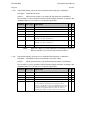
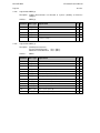
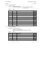
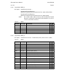
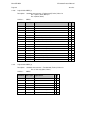
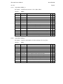
The following Tables indicate the Logical Node Description Lists. The “LN Types” that are
used for all Mx70 measurement products are found in Tables 4-10. It is necessary to use
the “LN Types” indicated to create the mapping necessary for the “LN Instance”. There are
tables for each of the following: M571, M572 Dual Feeder, M572 Breaker & ½, M871, M872
Dual Feeder, and M872 Breaker & ½. LN Type is remapped to LN Instance in order to
define each Logical Node per the standard, IEC 61850 Part 7. Tables 4-9 define the logical
devices, while table 10 defines the “LN Types”.
NOTE:
(applies for M87x tables 7-9)
GGIOx - The GGIO suffix number indicated by x in the LN instance name
represents the logical slot number that has been configured through the
70Series Configurator. A maximum number of 7 times the number of logical
nodes are possible with an M87x due to the logical slot configuration for LN
Instance. It is possible for the GGIO logical slots to range from 1 though 7 for
M87x. (i.e. GGIO1-GGIO7), which differs from M57x where the number of
logical slots is fixed at 1 (i.e. GGIO1).
During Configuration, Digital I/O slot numbers 0-6 map to logical slots GGIO1GGIO7. Transducer (Analogue) Input slot numbers 1-7 map to logical slots
GGIO1-GGIO7. For Digital I/O modules, P30 and P31, the slot numbers 0-6
must be incremented by 1 to obtain the GGIOx logical slot number, however for
Transducer Input module P40 the assigned slot number is the GGIO logical slot
number. For example if two Digital I/O modules are assigned to logical slot
numbers 0 and 2 and one Transducer (Analogue) Input module is assigned
logical slot 3, then GGIO1 would consist of one Digital I/O module, while GGIO3
would consist of 1 Digital I/O and 1 Transducer input module. However, if the
two Digital I/O modules are assigned to logical slot numbers 0 and 3 and the
(Analogue) Transducer Input module is assigned logical slot 3, then GGIO1
would consist of one Digital I/O module, GGIO3 would consist of 1 Transducer
input module, and GGIO4 would consist of 1 Digital I/O module.
For M87x models the total number of logical slots will depend upon the chassis
size, the number of slots that can be assigned for GGIO, and whether the digital
and analogue are grouped together (such as P30+P40 grouped together to
represent one logical node) or kept separate.
Please note that the P32 I/O wrap-around module serves a specialised function,
and therefore is not included in the IEC61850 object model for M87x Series
IEDs
IEC 61850 Protocol Manual
Mx7xI/EN M/M
70 series
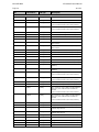
LD
Page 27
LN Instance
LN Type
Description
LLN0
LLN0_0
Measurements Logical Device
LPHD
LPHD_0
Physical Device Information
MMXU1
MMXU_10
Measurements
M571 Bus 1 (V,A,W,VAr) Measurements
(LN is extended to include custom measurements)
MMXU2
MMXU_11
M571 Bus 2 (V) Measurements
FndMMXU1
MMXU_7
Fundamental of Bus 1 (MMXU1) Measurements
FndMMXU2
MMXU_8
Fundamental of Bus 2 (MMXU2) Measurements
DmdMMXU1
MMXU_1
Present Thermal Demands of Bus 1 (MMXU1)
Measurements
DmdMMXU2
MMXU_2
Present Thermal Demands of Bus 2 (MMXU2)
Measurements
DmnMMXU1
MMXU_3
Minimum Thermal Demands of Bus 1 (MMXU1)
DmnMMXU2
MMXU_2
Minimum Thermal Demands of Bus 2 (MMXU2)
DmxMMXU1
MMXU_1
Maximum Thermal Demands of Bus 1 (MMXU1)
DmxMMXU2
MMXU_2
Maximum Thermal Demands of Bus 2 (MMXU2)
FndDmdMMXU1
MMXU_5
Fundamental Thermal Demands of Bus 1 (MMXU1)
FndDmxMMXU1
MMXU_5
Fundamental Maximum Thermal Demands of Bus 1
(MMXU1)
MMTR1
MMTR_0
(LN is extended to include custom measurements)
Bus 1 Energy Metering Measurement
(LN is extended to include custom measurements)
MSQI1
MSQI_0
Bus 1 Sequence Components (Volts & Amps)
MSQI2
MSQI_1
Bus 2 Sequence Components (Volts only)
MHAI1
MHAI_2
Bus 1 Harmonics (Volts & Amps) including individual
harmonics, phase related K factor and harmonic
demand
(LN is extended to include custom measurements)
MHAI2
MHAI_3
Bus 2 Harmonics (Volts only) including individual
harmonics and harmonic demand
DmdMHAI1
MHAI_0
Present Thermal Demands for Bus 1 (MHAI1)
DmdMHAI2
MHAI_1
Present Thermal Demands for Bus 2 (MHAI2) - Volts
only
DmnMHAI1
MHAI_1
Minimum Thermal Demands for Bus 1 (MHAI1)
No minimum Amp demands
-
DmnMHAI2
MHAI_1
Minimum Thermal Demands for Bus 2 (MHAI2)
Volts only
-
DmxMHAI1
MHAI_0
Maximum Thermal Demands for Bus 1 (MHAI1)
DmxMHAI2
MHAI_1
Maximum Thermal Demands for Bus 2 (MHAI2)
- Volts only
MLFK1
MLFK_0
Voltage Flicker Bus 1 Measurement (Custom LN)
MLFK2
MLFK_0
Voltage Flicker Bus 2 Measurement (Custom LN)
MSYN1
MSYN_0
Synch check Bus1 to Bus 2 Phase A (Custom LN)
MSYN2
MSYN_0
Synch check Bus1 to Bus 2 Phase B (Custom LN)
MSYN3
MSYN_0
Synch check Bus1 to Bus 2 Phase C (Custom LN)
MADV1
MADV_0
Advanced Measurements Bus 1 (Custom LN)
MFLO1
MFLO_0
Fault Distance Measurement Bus 1 (Custom LN)
MTMP1
MTMP_0
Temperature Measurement - internal ambient
(LN is extended to include custom measurements)
Mx7xI/EN M/M
IEC 61850 Protocol Manual
Page 28
LD
70 series
LN Instance
LN Type
Description
(Custom LN)
Records
LLN0
LLN0_0
Records Logical Device
LPHD
LDHD_0
Physical Device Information
WrxRDRE1
RDRE_0
Waveform Recorder 1
WrxRDRE2
RDRE_0
Waveform Recorder 2
DrxRDRE1
RDRE_0
Disturbance Recorder 1
DrxRDRE2
RDRE_0
Disturbance Recorder 2
LLN0
LLN0_1
System Logical Device
System
Can only Publish GOOSE in System/LLN0
LPHD
LPHD_0
Physical Device Information
GosGGIO1
GGIO_8
GOOSE Input Status
(GOOSE Subscriptions are done here)
TVTR1
TVTR_0
Voltage Transformer Phase A Bus 1
TVTR2
TVTR_0
Voltage Transformer Phase B Bus 1
TVTR3
TVTR_0
Voltage Transformer Phase C Bus 1
TVTR4
TVTR_0
Voltage Transformer Phase N Bus 1
TVTR5
TVTR_0
Voltage Transformer Phase A Bus 2
TVTR6
TVTR_0
Voltage Transformer Phase B Bus 2
TVTR7
TVTR_0
Voltage Transformer Phase C Bus 2
TVTR8
TVTR_0
Voltage Transformer Phase N Bus 2
TCTR1
TCTR_0
Current Transformer Phase A Bus 1
TCTR2
TCTR_0
Current Transformer Phase B Bus 1
TCTR3
TCTR_0
Current Transformer Phase C Bus 1
I/O Options (GGIO Logical slot number is fixed at 1).
Choose option
based on logical
slot configuration
No GGIO option
No GGIO option
No generic Process I/O
Choose option
based on logical
slot configuration
GGIO1
GGIO_0
Generic Process I/O
Choose option
based on logical
slot configuration
GGIO1
Choose option
based on logical
slot configuration
GGIO1
GGIO for M57x: 4DI/4DO
GGIO_3
Generic Process I/O
GGIO for M57x: 4DI/4DO/4AI
GGIO_6
Generic Process I/O
GGIO for M57x: /4AI
GGIO2
GGIO_9
Generic Process I/O – 32 Virtual Output signals
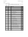
TABLE 4 - M571
IEC 61850 Protocol Manual
Mx7xI/EN M/M
70 series
LD
Page 29
LN Instance
LN Type
Description
LLN0
LLN0_0
Measurements Logical Device
LPHD
LPHD_0
Physical Device Information
MMXU1
MMXU_10
Measurements
M572 Bus 1 (V,A,W,VAr) Measurements
(LN is extended to include custom measurements)
MMXU2
MMXU_10
M572 Bus 2 (V,A,W,VAr) Measurements
MMXN1
MMXN_0
M572 Dual Feeder Voltage Reference 1 (V)
MMXN2
MMXN_0
M572 Dual Feeder Voltage Reference 2 (V)
FndMMXU1
MMXU_7
Fundamental of Bus 1 (MMXU1) Measurements
FndMMXU2
MMXU_7
Fundamental of Bus 2 (MMXU2) Measurements
DmdMMXU1
MMXU_1
Present Thermal Demands of Bus 1 (MMXU1)
Measurements
DmdMMXU2
MMXU_1
Present Thermal Demands of Bus 2 (MMXU2)
Measurements
DmnMMXU1
MMXU_3
Minimum Thermal Demands of Bus 1 (MMXU1)
DmnMMXU2
MMXU_3
Minimum Thermal Demands of Bus 2 (MMXU2)
DmxMMXU1
MMXU_1
Maximum Thermal Demands of Bus 1 (MMXU1)
DmxMMXU2
MMXU_1
Maximum Thermal Demands of Bus 2 (MMXU2)
FndDmdMMXU1
MMXU_5
Fundamental Thermal Demands of Bus 1 (MMXU1)
FndDmdMMXU2
MMXU_5
Fundamental Thermal Demands of Bus 2 (MMXU2)
FndDmxMMXU1
MMXU_5
Fundamental Maximum Thermal Demands of Bus 1
(MMXU1)
FndDmxMMXU2
MMXU_5
Fundamental Maximum Thermal Demands of Bus 2
(MMXU2)
MMTR1
MMTR_0
(LN is extended to include custom measurements)
Bus 1 Energy Metering Measurement
(LN is extended to include custom measurements)
MMTR2
MMTR_0
Bus 2 Energy Metering Measurement
(LN is extended to include custom measurements)
MSQI1
MSQI_0
Bus 1 Sequence Components (Volts & Amps)
MSQI2
MSQI_0
Bus 2 Sequence Components (Volts & Amps)
MHAI1
MHAI_2
Bus 1 Harmonics (Volts & Amps) including individual
harmonics, phase related K factor and harmonic
demand
(LN is extended to include custom measurements)
MHAI2
MHAI_2
Bus 2 Harmonics (Volts & Amps) including individual
harmonics, phase related K factor and harmonic
demand
(LN is extended to include custom measurements)
DmdMHAI1
MHAI_0
Present Thermal Demands for Bus 1 (MHAI1)
DmdMHAI2
MHAI_0
Present Thermal Demands for Bus 2 (MHAI2)
DmnMHAI1
MHAI_1
Minimum Thermal Demands for Bus 1 (MHAI1)
- (No minimum Amp demands
DmnMHAI2
MHAI_1
Minimum Thermal Demands for Bus 2 (MHAI2) -No
minimum Amp demands
DmxMHAI1
MHAI_0
Maximum Thermal Demands for Bus 1 (MHAI1)
DmxMHAI2
MHAI_0
Maximum Thermal Demands for Bus 2 (MHAI2)
MLFK1
MLFK_0
Voltage Flicker Bus 1 Measurement (Custom LN)
MLFK2
MLFK_0
Voltage Flicker Bus 2 Measurement (Custom LN)
Mx7xI/EN M/M
IEC 61850 Protocol Manual
Page 30
LD
70 series
LN Instance
LN Type
Description
MSYN1
MSYN_0
Synch check Bus 1 Phase A to VREF1 for M572
(Dual Feeder) (Custom LN)
MSYN2
MSYN_0
Synch check Bus 1 Phase B to VREF1
(Custom LN)
MSYN3
MSYN_0
Synch check Bus 1 Phase C to VREF1
(Custom LN)
MSYN4
MSYN_0
Synch check Bus 1 Phase A to VREF2
(Custom LN)
MSYN5
MSYN_0
Synch check Bus 1 Phase B to VREF2
(Custom LN)
MSYN6
MSYN_0
Synch check Bus 1 Phase C to VREF2
(Custom LN)
MADV1
MADV_0
Advanced Measurements Bus 1 (Custom LN)
MADV2
MADV_0
Advanced Measurements Bus 2 (Custom LN)
MFLO1
MFLO_0
Fault Distance Measurement Bus 1 (Custom LN)
MFLO2
MFLO_0
Fault Distance Measurement Bus 2 (Custom LN)
MTMP1
MTMP_0
Temperature Measurement – Internal ambient
(Custom LN)
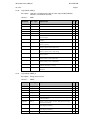
LLN0
LLN0_0
Records Logical Device
LPHD
LDHD_0
Physical Device Information
WrxRDRE1
RDRE_0
Waveform Recorder 1
WrxRDRE2
RDRE_0
Waveform Recorder 2
DrxRDRE1
RDRE_0
Disturbance Recorder 1
DrxRDRE2
RDRE_0
Disturbance Recorder 2
LLN0
LLN0_1
System Logical Device
Records
System
Can only Publish GOOSE in System/LLN0
LPHD
LPHD_0
Physical Device Information
GosGGIO1
GGIO_8
GOOSE Input Status
(GOOSE Subscriptions are done here)
TVTR1
TVTR_0
Voltage Transformer Phase A Bus 1
TVTR2
TVTR_0
Voltage Transformer Phase B Bus 1
TVTR3
TVTR_0
Voltage Transformer Phase C Bus 1
TVTR4
TVTR_0
Voltage Transformer Phase N Bus 1
TVTR5
TVTR_0
Voltage Transformer Phase A Bus 2
TVTR6
TVTR_0
Voltage Transformer Phase B Bus 2
TVTR7
TVTR_0
Voltage Transformer Phase C Bus 2
TVTR8
TVTR_0
Voltage Transformer Phase N Bus 2
TVTR9
TVTR_0
Voltage Transformer for Vref1
TVTR10
TVTR_0
Voltage Transformer for Vref2
TCTR1
TCTR_0
Current Transformer Phase A Bus 1
TCTR2
TCTR_0
Current Transformer Phase B Bus 1
TCTR3
TCTR_0
Current Transformer Phase C Bus 1
TCTR5
TCTR_0
Current Transformer Phase A Bus 2
TCTR6
TCTR_0
Current Transformer Phase B Bus 2
TCTR7
TCTR_0
Current Transformer Phase C Bus 2
IEC 61850 Protocol Manual
Mx7xI/EN M/M
70 series
LD
System
Page 31
LN Instance
LN Type
Description
I/O Options (GGIO Logical slot number is fixed at 1).
Choose option
based on logical
slot configuration
No GGIO option
No GGIO option
No generic Process I/O
Choose option
based on logical
slot configuration
GGIO1
GGIO_0
Generic Process I/O
Choose option
based on logical
slot configuration
GGIO1
Choose option
based on logical
slot configuration
GGIO1
GGIO for M57x: 4DI/4DO
GGIO_3
Generic Process I/O
GGIO for M57x: 4DI/4DO/4AI
GGIO_6
Generic Process I/O
GGIO for M57x: /4AI
GGIO2
GGIO_9
Generic Process I/O – 32 Virtual Output signals
TABLE 5 - M572 DUAL FEEDER
Mx7xI/EN M/M
IEC 61850 Protocol Manual
Page 32
LD
70 series
LN Instance
LN Type
Description
LLN0
LLN0_0
Measurements Logical Device
LPHD
LPHD_0
Physical Device Information
MMXU1
MMXU_10
M572 Bus 1 (V,A,W,VAr) Measurements
Measurements
(LN is extended to include custom measurements)
MMXU2
MMXU_10
M572 Bus 2 (V,A,W,VAr) Measurements
FndMMXU1
MMXU_7
Fundamental of Bus 1 (MMXU1) Measurements
FndMMXU2
MMXU_7
Fundamental of Bus 2 (MMXU2) Measurements
DmdMMXU1
MMXU_1
Present Thermal Demands of Bus 1 (MMXU1)
Measurements
DmdMMXU2
MMXU_1
Present Thermal Demands of Bus 2 (MMXU2)
Measurements
DmnMMXU1
MMXU_3
Minimum Thermal Demands of Bus 1 (MMXU1)
DmnMMXU2
MMXU_3
Minimum Thermal Demands of Bus 2 (MMXU2)
DmxMMXU1
MMXU_1
Maximum Thermal Demands of Bus 1 (MMXU1)
DmxMMXU2
MMXU_1
Maximum Thermal Demands of Bus 2 (MMXU2)
FndDmdMMXU1
MMXU_5
Fundamental Thermal Demands of Bus 1 (MMXU1)
FndDmdMMXU2
MMXU_5
Fundamental Thermal Demands of Bus 2 (MMXU2)
FndDmxMMXU1
MMXU_5
Fundamental Maximum Thermal Demands of Bus 1
(MMXU1)
FndDmxMMXU2
MMXU_5
Fundamental Maximum Thermal Demands of Bus 2
(MMXU2)
MMTR1
MMTR_0
Bus 1 Energy Metering Measurement
(LN is extended to include custom measurements)
(LN is extended to include custom measurements)
MMTR2
MMTR_0
Bus 2 Energy Metering Measurement
(LN is extended to include custom measurements)
MSQI1
MSQI_0
Bus 1 Sequence Components (Volts & Amps)
MSQI2
MSQI_0
Bus 2 Sequence Components (Volts & Amps)
MHAI1
MHAI_2
Bus 1 Harmonics (Volts & Amps) including individual
harmonics, phase related K factor and harmonic
demand
(LN is extended to include custom measurements)
MHAI2
MHAI_2
Bus 2 Harmonics (Volts & Amps) including individual
harmonics, phase related K factor and harmonic
demand
DmdMHAI1
MHAI_0
Present Thermal Demands for Bus 1 (MHAI1)
DmdMHAI2
MHAI_0
Present Thermal Demands for Bus 2 (MHAI3)
DmnMHAI1
MHAI_1
Minimum Thermal Demands for Bus 1 (MHAI1) - No
minimum Amp demands
DmnMHAI2
MHAI_1
Minimum Thermal Demands for Bus 2 (MHAI2) - No
minimum Amp demands
DmxMHAI1
MHAI_0
Maximum Thermal Demands for Bus 1 (MHAI1)
DmxMHAI2
MHAI_0
Maximum Thermal Demands for Bus 2 (MHAI2)
MLFK1
MLFK_0
Voltage Flicker Bus 1 Measurement (Custom LN)
MLFK2
MLFK_0
Voltage Flicker Bus 2 Measurement (Custom LN)
MSYN1
MSYN_0
Synch check Bus1 to Bus 2 Phase A for M572
Breaker & ½ (Custom LN)
(LN is extended to include custom measurements)
IEC 61850 Protocol Manual
Mx7xI/EN M/M
70 series
LD
Page 33
LN Instance
LN Type
Description
MSYN2
MSYN_0
Synch check Bus1 to Bus 2 Phase B for M572
Breaker & ½ (Custom LN)
MSYN3
MSYN_0
Synch check Bus1 to Bus 2 Phase C for M572
Breaker & ½ (Custom LN)
MADV1
MADV_0
Advanced Measurements Bus 1 (Custom LN)
MADV2
MADV_0
Advanced Measurements Bus 2 (Custom LN)
MFLO1
MFLO_0
Fault Distance Measurement Bus 1 (Custom LN)
MFLO2
MFLO_0
Fault Distance Measurement Bus 2 (Custom LN)
MTMP1
MTMP_0
Temperature Measurement – Internal ambient
(Custom LN)
Records
LLN0
LLN0_0
Records Logical Device
LPHD
LDHD_0
Physical Device Information
WrxRDRE1
RDRE_0
Waveform Recorder 1
WrxRDRE2
RDRE_0
Waveform Recorder 2
DrxRDRE1
RDRE_0
Disturbance Recorder 1
DrxRDRE2
RDRE_0
Disturbance Recorder 2
LLN0
LLN0_1
System Logical Device
LPHD
LPHD_0
Physical Device Information
GosGGIO1
GGIO_8
GOOSE Input Status
TVTR1
TVTR_0
Voltage Transformer Phase A Bus 1
TVTR2
TVTR_0
Voltage Transformer Phase B Bus 1
TVTR3
TVTR_0
Voltage Transformer Phase C Bus 1
TVTR4
TVTR_0
Voltage Transformer Phase N Bus 1
TVTR5
TVTR_0
Voltage Transformer Phase A Bus 2
TVTR6
TVTR_0
Voltage Transformer Phase B Bus 2
TVTR7
TVTR_0
Voltage Transformer Phase C Bus 2
TVTR8
TVTR_0
Voltage Transformer Phase N Bus 2
TCTR1
TCTR_0
Current Transformer Phase A Bus 1
TCTR2
TCTR_0
Current Transformer Phase B Bus 1
TCTR3
TCTR_0
Current Transformer Phase C Bus 1
TCTR5
TCTR_0
Current Transformer Phase A Bus 2
TCTR6
TCTR_0
Current Transformer Phase B Bus 2
TCTR7
TCTR_0
Current Transformer Phase C Bus 2
System
Can only Publish GOOSE in System/LLN0
(GOOSE Subscriptions are done here)
Mx7xI/EN M/M
IEC 61850 Protocol Manual
Page 34
LD
System
70 series
LN Instance
LN Type
Description
I/O Options (GGIO Logical slot number is fixed at 1).
Choose option
based on logical
slot configuration
No GGIO option
No
GGIO
option
No generic Process I/O
Choose option
based on logical
slot configuration
GGIO1
GGIO_0
Generic Process I/O
Choose option
based on logical
slot configuration
GGIO1
Choose option
based on logical
slot configuration
GGIO1
GGIO for M57x: 4DI/4DO
GGIO_3
Generic Process I/O
GGIO for M57x: 4DI/4DO/4AI
GGIO_6
Generic Process I/O
GGIO for M57x: /4AI
GGIO2
GGIO_9
Generic Process I/O – 32 Virtual Output signals
TABLE 6 - M572 BREAKER AND ½
IEC 61850 Protocol Manual
Mx7xI/EN M/M
70 series
LD
Page 35
LN Instance
LN Type
Description
LLN0
LNN0_0
Measurements Logical Device
LPHD
LPHD_0
Physical Device Information
MMXU1
MMXU_9
Measurements
M871 Bus 1 (V,A, W, VAr) Measurements
(LN is extended to include custom measurements)
MMXU2
MMXU_11
M871 Bus 2 (V) Measurements
MMXN1
MMXN_0
M871 Auxiliary voltage 1 (V)
MMXN2
MMXN_0
M871 Auxiliary voltage 2 (V)
MMXN3
MMXN_0
M871 Auxiliary differential voltage (V)
FndMMXU1
MMXU_6
Fundamental Measurements of Bus 1 (MMXU1)
FndMMXU2
MMXU_8
Fundamental Measurements of Bus 2 (MMXU2)
DmdMMXU1
MMXU_0
Present Thermal Demands of Bus 1 (MMXU1)
Measurements
DmdMMXU2
MMXU_2
Present Thermal Demands of Bus 2 (MMXU2)
Measurements
DmnMMXU1
MMXU_3
Minimum Thermal Demands of Bus 1 (MMXU1)
DmnMMXU2
MMXU_2
Minimum Thermal Demands of Bus 2 (MMXU2)
DmxMMXU1
MMXU_0
Maximum Thermal Demands of Bus 1 (MMXU1)
(LN is extended to include custom measurements)
DmxMMXU2
MMXU_2
Maximum Thermal Demands of Bus 2 (MMXU2)
FndDmdMMXU1
MMXU_4
Fundamental Thermal Demands of Bus 1 (MMXU1)
FndDmxMMXU1
MMXU_4
Fundamental Maximum Thermal Demands of Bus 1
(MMXU1)
MMTR1
MMTR_0
Bus 1 Energy Metering Measurement
(LN is extended to include custom measurements)
MSQI1
MSQI_0
Bus 1 Sequence Components (Volts & Amps)
MSQI2
MSQI_1
Bus 2 Sequence Components (Volts only)
MHAI1
MHAI_2
Bus 1 Harmonics (Volts & Amps) including individual
harmonics, phase related K factor and harmonic
demand
(LN is extended to include custom measurements)
MHAI2
MHAI_3
Bus 2 Harmonics (Volts only) including individual
harmonics and harmonic demand
DmdMHAI1
MHAI_0
Present Thermal Demands for Bus 1 (MHAI1)
DmdMHAI2
MHAI_1
Present Thermal Demands for Bus 2 (MHAI2) – Volts
only
DmnMHAI1
MHAI_1
Minimum Thermal Demands for Bus 1 (MHAI1) – No
minimum Amp demands
DmnMHAI2
MHAI_1
Minimum Thermal Demands for Bus 2 (MHAI2) - Volts
only
DmxMHAI1
MHAI_0
Maximum Thermal Demands for Bus 1 (MHAI1)
DmxMHAI2
MHAI_1
Maximum Thermal Demands for Bus 2 (MHAI2) –
Volts only
MLFK1
MLFK_0
Voltage Flicker Bus 1 Measurement (Custom LN)
MLFK2
MLFK_0
Voltage Flicker Bus 2 Measurement (Custom LN)
MSYN1
MSYN_0
Synch check Bus1 to Bus 2 Phase A (Custom LN)
MSYN2
MSYN_0
Synch check Bus1 to Bus 2 Phase B (Custom LN)
MSYN3
MSYN_0
Synch check Bus1 to Bus 2 Phase C (Custom LN)
(LN is extended to include custom measurements)
Mx7xI/EN M/M
IEC 61850 Protocol Manual
Page 36
LD
70 series
LN Instance
LN Type
Description
MADV1
MADV_0
Advanced Measurements Bus 1 (Custom LN)
MFLO1
MFLO_0
Fault Distance Measurement Bus 1 (Custom LN)
MTMP1
MTMP_0
Temperature Measurement –Internal ambient
(Custom LN)
Records
LLN0
LLN0_0
Records Logical Device
LPHD
LDHD_0
Physical Device Information
WrxRDRE1
RDRE_0
Waveform Recorder 1
WrxRDRE2
RDRE_0
Waveform Recorder 2
DrxRDRE1
RDRE_0
Disturbance Recorder 1
DrxRDRE2
RDRE_0
Disturbance Recorder 2
LLN0
LLN0_1
System Logical Device
LPHD
LPHD_0
Physical Device Information
GosGGIO1
GGIO_8
GOOSE Input Status
TVTR1
TVTR_0
Voltage Transformer Phase A Bus 1
TVTR2
TVTR_0
Voltage Transformer Phase B Bus 1
TVTR3
TVTR_0
Voltage Transformer Phase C Bus 1
TVTR4
TVTR_0
Voltage Transformer Phase N Bus 1
TVTR5
TVTR_0
Voltage Transformer Phase A Bus 2
TVTR6
TVTR_0
Voltage Transformer Phase B Bus 2
TVTR7
TVTR_0
Voltage Transformer Phase C Bus 2
TVTR8
TVTR_0
Voltage Transformer Phase N Bus 2
TVTR9
TVTR_0
Voltage Transformer - Auxiliary voltage 1
TVTR10
TVTR_0
Voltage Transformer - Auxiliary voltage 2
TVTR11
TVTR_0
Voltage Transformer - differential auxiliary voltage
TCTR1
TCTR_0
Current Transformer Phase A Bus 1
TCTR2
TCTR_0
Current Transformer Phase B Bus 1
TCTR3
TCTR_0
Current Transformer Phase C Bus 1
TCTR4
TCTR_0
Current Transformer Phase N Bus 1
System
Can only Publish GOOSE in System/LLN0
(GOOSE Subscriptions are done here)
IEC 61850 Protocol Manual
Mx7xI/EN M/M
70 series
System
Page 37
I/O Options (GGIO Logical slot numbers may range from 1 -7).
Chose option based
on logical slot
configuration
No GGIO option
No GGIO option
No generic Process I/O
Chose option based
on logical slot
configuration
GGIOx
GGIO_1
Generic Process I/O (P30)
Chose option based
on logical slot
configuration
GGIOx
Chose option based
on logical slot
configuration
GGIOx
Chose option based
on logical
configuration
GGIOx
Chose option based
on logical slot
configuration
GGIOx
(see Note 1)
GGIO for logical slot x-1: 8DI/4DO
GGIO_2
(see Note 1)
GGIO for logical slot x-1: 16DI/4DO
GGIO_4
(see Note 1)
Generic Process I/O (P30+P40)
GGIO for logical slot x-1 (P30) & logical slot x (P40):
8DI/4DO/8AI
GGIO_5
(see Note 1)
Generic Process I/O (P31+P40)
GGIO for logical slot x-1 (P31) & logical slot x (P40):
16DI/4DO/8AI
GGIO_7
(see Note 1)
GGIO2
Generic Process I/O (P31)
Generic Process I/O (P40)
GGIO for logical slot x: /8AI
GGIO_9
Generic Process I/O – 32 Virtual Output signals
TABLE 7 - M871
Mx7xI/EN M/M
IEC 61850 Protocol Manual
Page 38
LD
70 series
LN Instance
LN Type
Description
LLN0
LLN0_0
Measurements Logical Device
LPHD
LPHD_0
Physical Device Information
MMXU1
MMXU_10
M872 Bus 1 (V,A,W,VAr) Measurements
Measurements
(LN is extended to include custom measurements)
MMXU2
MMXU_10
M872 Bus 2 (V,A,W,VAr) Measurements
MMXN1
MMXN_0
M872 Dual Feeder Voltage Reference 1 (V)
MMXN2
MMXN_0
M872 Dual Feeder Voltage Reference 2 (V)
FndMMXU1
MMXU_7
Fundamental Measurements of Bus 1 (MMXU1)
FndMMXU2
MMXU_7
Fundamental Measurements of Bus 2 (MMXU2)
DmdMMXU1
MMXU_1
Present Thermal Demands of Bus 1 (MMXU1)
Measurements
DmdMMXU2
MMXU_1
Present Thermal Demands of Bus 2 (MMXU2)
Measurements
DmnMMXU1
MMXU_3
Minimum Thermal Demands of Bus 1 (MMXU1)
DmnMMXU2
MMXU_3
Minimum Thermal Demands of Bus 2 (MMXU2)
DmxMMXU1
MMXU_1
Maximum Thermal Demands of Bus 1 (MMXU1)
DmxMMXU2
MMXU_1
Maximum Thermal Demands of Bus 2 (MMXU2)
FndDmdMMXU1
MMXU_5
Fundamental Thermal Demands of Bus 1 (MMXU1)
FndDmdMMXU2
MMXU_5
Fundamental Thermal Demands of Bus 2 (MMXU2)
FndDmxMMXU1
MMXU_5
Fundamental Maximum Thermal Demands of Bus 1
(MMXU1)
FndDmxMMXU2
MMXU_5
Fundamental Maximum Thermal Demands of Bus 2
(MMXU2)
MMTR1
MMTR_0
Bus 1 Energy Metering Measurement
(LN is extended to include custom measurements)
(LN is extended to include custom measurements)
MMTR2
MMTR_0
Bus 2 Energy Metering Measurement
(LN is extended to include custom measurements)
MSQI1
MSQI_0
Bus 1 Sequence Components (Volts & Amps)
MSQI2
MSQI_0
Bus 2 Sequence Components (Volts & Amps)
MHAI1
MHAI_2
Bus 1 Harmonics (Volts & Amps) including individual
harmonics, phase related K factor and harmonic
demand
(LN is extended to include custom measurements)
MHAI2
MHAI_2
Bus 2 Harmonics (Volts & Amps) including individual
harmonics, phase related K factor and harmonic
demand
(LN is extended to include custom measurements)
DmdMHAI1
MHAI_0
Present Thermal Demands for Bus 1 (MHAI1)
DmdMHAI2
MHAI_0
Present Thermal Demands for Bus 2 (MHAI2)
DmnMHAI1
MHAI_1
Minimum Thermal Demands for Bus 1 (MHAI1) – No
minimum Amp demands
DmnMHAI2
MHAI_1
Minimum Thermal Demands for Bus 2 (MHAI2) - No
minimum Amp demands
DmxMHAI1
MHAI_0
Maximum Thermal Demands for Bus 1 (MHAI1)
DmxMHAI2
MHAI_0
Maximum Thermal Demands for Bus 2 (MHAI2)
MLFK1
MLFK_0
Voltage Flicker Bus 1 Measurement (Custom LN)
MLFK2
MLFK_0
Voltage Flicker Bus 2 Measurement (Custom LN)
MSYN1
MSYN_0
Synch check Bus 1, Phase A to VREF1 (Custom LN)
IEC 61850 Protocol Manual
Mx7xI/EN M/M
70 series
LD
Page 39
LN Instance
LN Type
Description
MSYN2
MSYN_0
Synch check Bus 1 Phase B to VREF1 (Custom LN)
MSYN3
MSYN_0
Synch check Bus 1 Phase C to VREF1 (Custom LN)
MSYN4
MSYN_0
Synch check Bus 1 Phase A to VREF2 (Custom LN)
MSYN5
MSYN_0
Synch check Bus 1 Phase B to VREF2 (Custom LN)
MSYN6
MSYN_0
Synch check Bus 1 Phase C to VREF2 (Custom LN)
MADV1
MADV_0
Advanced Measurements Bus 1 (Custom LN)
MADV2
MADV_0
Advanced Measurements Bus 2 (Custom LN)
MFLO1
MFLO_0
Fault Distance Measurement Bus 1 (Custom LN)
MFLO2
MFLO_0
Fault Distance Measurement Bus 2 (Custom LN)
MTMP1
MTMP_0
Temperature Measurement- internal ambient
(Custom LN)
LLN0
LLN0_0
Records Logical Device
LPHD
LDHD_0
Physical Device Information
WrxRDRE1
RDRE_0
Waveform Recorder 1
WrxRDRE2
RDRE_0
Waveform Recorder 2
DrxRDRE1
RDRE_0
Disturbance Recorder 1
DrxRDRE2
RDRE_0
Disturbance Recorder 2
LLN0
LLN0_1
Records
System
System Logical Device
Can only Publish GOOSE in System/LLN0
LPHD
LPHD_0
GosGGIO1
GGIO_8
Physical Device Information
GOOSE Input Status
(GOOSE Subscriptions are done here)
TVTR1
TVTR_0
Voltage Transformer Phase A Bus 1
TVTR2
TVTR_0
Voltage Transformer Phase B Bus 1
TVTR3
TVTR_0
Voltage Transformer Phase C Bus 1
TVTR4
TVTR_0
Voltage Transformer Phase N Bus 1
TVTR5
TVTR_0
Voltage Transformer Phase A Bus 2
TVTR6
TVTR_0
Voltage Transformer Phase B Bus 2
TVTR7
TVTR_0
Voltage Transformer Phase C Bus 2
TVTR8
TVTR_0
Voltage Transformer Phase N Bus 2
TVTR9
TVTR_0
Voltage Transformer for Vref1
TVTR10
TVTR_0
Voltage Transformer for Vref2
TCTR1
TCTR_0
Current Transformer Phase A Bus 1
TCTR2
TCTR_0
Current Transformer Phase B Bus 1
TCTR3
TCTR_0
Current Transformer Phase C Bus 1
TCTR5
TCTR_0
Current Transformer Phase A Bus 2
TCTR6
TCTR_0
Current Transformer Phase B Bus 2
TCTR7
TCTR_0
Current Transformer Phase C Bus 2
Mx7xI/EN M/M
IEC 61850 Protocol Manual
Page 40
System
70 series
I/O Options (GGIO Logical slot numbers may range from 1-7).
Choose option
based on logical
slot configuration
No GGIO option
No GGIO option
No generic Process I/O
Choose option
based on logical
slot configuration
GGIOx
GGIO_1
Generic Process I/O (P30)
Choose option
based on logical
slot configuration
GGIOx
Choose option
based on logical
slot configuration
GGIOx
Choose option
based on logical
slot configuration
GGIOx
Choose option
based on logical
slot configuration
GGIOx
(see Note 1)
GGIO for logical slot x-1: 8DI/4DO
GGIO_2
(see Note 1)
GGIO for logical slot x-1: 16DI/4DO
GGIO_4
(see Note 1)
Generic Process I/O (P30+P40)
GGIO for logical slot x-1 (P30) & logical slot x (P40):
8DI/4DO/8AI
GGIO_5
(see Note 1)
Generic Process I/O (P31+P40)
GGIO for logical slot x-1 (P31) & logical slot x (P40):
16DI/4DO/8AI
GGIO_7
(see Note 1)
GGIO2
Generic Process I/O (P31)
Generic Process I/O (P40)
GGIO for logical slot x: /8AI
GGIO_9
Generic Process I/O – 32 Virtual Output signals
TABLE 8 - M872 DUAL FEEDER
IEC 61850 Protocol Manual
Mx7xI/EN M/M
70 series
LD
Page 41
LN Instance
LN Type
Description
LLN0
LLN0_0
Measurements Logical Device
LPHD
LPHD_0
Physical Device Information
MMXU1
MMXU_10
Measurements
M872 Bus 1 (V,A,W,VAr) Measurements
(LN is extended to include custom measurements)
MMXU2
MMXU_10
M872 Bus 2 (V,A,W,VAr) Measurements
FndMMXU1
MMXU_7
Fundamental of Bus 1 (MMXU1) Measurements
FndMMXU2
MMXU_7
Fundamental of Bus 2 (MMXU2) Measurements
DmdMMXU1
MMXU_1
Present Thermal Demands of Bus 1 (MMXU1)
Measurements
DmdMMXU2
MMXU_1
Present Thermal Demands of Bus 2 (MMXU2)
Measurements
DmnMMXU1
MMXU_3
Minimum Thermal Demands of Bus 1 (MMXU1)
DmnMMXU2
MMXU_3
Minimum Thermal Demands of Bus 2 (MMXU2)
DmxMMXU1
MMXU_1
Maximum Thermal Demands of Bus 1 (MMXU1)
DmxMMXU2
MMXU_1
Maximum Thermal Demands of Bus 2 (MMXU2)
FndDmdMMXU1
MMXU_5
Fundamental Thermal Demands of Bus 1 (MMXU1)
FndDmdMMXU2
MMXU_5
Fundamental Thermal Demands of Bus 2 (MMXU2)
FndDmxMMXU1
MMXU_5
Fundamental Maximum Thermal Demands of Bus 1
(MMXU1)
FndDmxMMXU2
MMXU_5
Fundamental Maximum Thermal Demands of Bus 2
(MMXU2)
MMTR1
MMTR_0
Bus 1 Energy Metering Measurement
(LN is extended to include custom measurements)
(LN is extended to include custom measurements)
MMTR2
MMTR_0
Bus 2 Energy Metering Measurement
(LN is extended to include custom measurements)
MSQI1
MSQI_0
Bus 1 Sequence Components (Volts & Amps)
MSQI2
MSQI_0
Bus 2 Sequence Components (Volts & Amps)
MHAI1
MHAI_2
Bus 1 Harmonics (Volts & Amps) including individual
harmonics, phase related K factor and harmonic
demand
(LN is extended to include custom measurements)
MHAI2
MHAI_2
Bus 2 Harmonics (Volts & Amps) including individual
harmonics, phase related K factor and harmonic
demand
DmdMHAI1
MHAI_0
Present Thermal Demands for Bus 1 (MHAI1)
DmdMHAI2
MHAI_0
Present Thermal Demands for Bus 2 (MHAI2)
DmnMHAI1
MHAI_1
Minimum Thermal Demands for Bus 1 ( MHAI1) - No
minimum Amp demands
DmnMHAI2
MHAI_1
Minimum Thermal Demands for Bus 2 (MHAI2) - No
minimum Amp demands
DmxMHAI1
MHAI_0
Maximum Thermal Demands for Bus 1 (MHAI1)
DmxMHAI2
MHAI_0
Maximum Thermal Demands for Bus 2 (MHAI2)
MLFK1
MLFK_0
Voltage Flicker Bus 1 Measurement (Custom LN)
MLFK2
MLFK_0
Voltage Flicker Bus 2 Measurement (Custom LN)
MSYN1
MSYN_0
Synch check Bus1 to Bus 2 Phase A for M872
(Breaker & 1/2) (Custom LN)
(LN is extended to include custom measurements)
Mx7xI/EN M/M
IEC 61850 Protocol Manual
Page 42
LD
70 series
LN Instance
LN Type
Description
MSYN2
MSYN_0
Synch check Bus1 to Bus 2 Phase B for M872
(Breaker & 1/2) (Custom LN)
MSYN3
MSYN_0
Synch check Bus1 to Bus 2 Phase C for M872
(Breaker & 1/2) (Custom LN)
MADV1
MADV_0
Advanced Measurements Bus 1 (Custom LN)
MADV2
MADV_0
Advanced Measurements Bus 2 (Custom LN)
MFLO1
MFLO_0
Fault Distance Measurement Bus 1 (Custom LN)
MFLO2
MFLO_0
Fault Distance Measurement Bus 2 (Custom LN)
MTMP1
MTMP_0
Temperature Measurement – internal ambient
(Custom LN)
Records
LLN0
LLN0_0
Records Logical Device
LPHD
LDHD_0
Physical Device Information
WrxRDRE1
RDRE_0
Waveform Recorder 1
WrxRDRE2
RDRE_0
Waveform Recorder 2
DrxRDRE1
RDRE_0
Disturbance Recorder 1
DrxRDRE2
RDRE_0
Disturbance Recorder 2
LLN0
LLN0_1
System Logical Device
LPHD
LPHD_0
Physical Device Information
GosGGIO1
GGIO_8
GOOSE Input Status
TVTR1
TVTR_0
Voltage Transformer Phase A Bus 1
TVTR2
TVTR_0
Voltage Transformer Phase B Bus 1
TVTR3
TVTR_0
Voltage Transformer Phase C Bus 1
TVTR4
TVTR_0
Voltage Transformer Phase N Bus 1
TVTR5
TVTR_0
Voltage Transformer Phase A Bus 2
TVTR6
TVTR_0
Voltage Transformer Phase B Bus 2
TVTR7
TVTR_0
Voltage Transformer Phase C Bus 2
TVTR8
TVTR_0
Voltage Transformer Phase N Bus 2
TCTR1
TCTR_0
Current Transformer Phase A Bus 1
TCTR2
TCTR_0
Current Transformer Phase B Bus 1
TCTR3
TCTR_0
Current Transformer Phase C Bus 1
TCTR5
TCTR_0
Current Transformer Phase A Bus 2
TCTR6
TCTR_0
Current Transformer Phase B Bus 2
TCTR7
TCTR_0
Current Transformer Phase C Bus 2
System
Can only Publish GOOSE in System/LLN0
(GOOSE Subscriptions are done here)
IEC 61850 Protocol Manual
Mx7xI/EN M/M
70 series
System
Page 43
I/O Options (GGIO Logical slot numbers may range from 1 -7).
Choose option
based on logical
slot configuration
No GGIO option
No GGIO option
No generic Process I/O
Choose option
based on logical
slot configuration
GGIOx
GGIO_1
Generic Process I/O (P30)
Choose option
based on logical
slot configuration
GGIOx
Choose option
based on logical
slot configuration
GGIOx
Choose option
based on logical
slot configuration
GGIOx
Choose option
based on logical
slot configuration
GGIOx
(see Note 1)
GGIO for logical slot x-1: 8DI/4DO
GGIO_2
(see Note 1)
GGIO for logical slot x-1: 16DI/4DO
GGIO_4
(see Note 1)
Generic Process I/O (P30+P40)
GGIO for logical slot x-1 (P30) & logical slot x (P40):
8DI/4DO/8AI
GGIO_5
(see Note 1)
Generic Process I/O (P31+P40)
GGIO for logical slot x-1 (P31) & logical slot x (P40):
16DI/4DO/8AI
GGIO_7
(see Note 1)
GGIO2
Generic Process I/O (P31)
Generic Process I/O (P40)
GGIO for logical slot x:
GGIO_9
/8AI
Generic Process I/O – 32 Virtual Output signals
TABLE 9 - M872 BREAKER AND ½
Mx7xI/EN M/M
IEC 61850 Protocol Manual
Page 44
3.4
70 series
Logical Node definitions
The definition tables for each of the Logical Nodes in the top-level data model are presented
in the following sub-sections.
The following table presents a summary of the Logical Node templates used across the
Logical Devices within the overall IEC 61850 product data model:
LN Type
(LN Class)
Description
Name Space
GGIO_0
(GGIO)
Generic Process I/O – M57x with option of 4 Digital Inputs / 4
Digital Outputs
IEC 61850-7-4:2003
GGIO_1
(GGIO)
Generic Process I/O – M87x with option of 8 Digital Inputs/4
Digital Outputs
IEC 61850-7-4:2003
GGIO_2
(GGIO)
Generic Process I/O – M87x with option of 16 Digital inputs/4
Digital outputs
IEC 61850-7-4:2003
GGIO_3
(GGIO)
Generic Process I/O – M57x with option of 4 Digital Inputs/ 4
Digital Outputs/ 4 Analogue Inputs
IEC 61850-7-4:2003
GGIO_4
(GGIO)
Generic Process I/O – M87x with options of 8 Digital inputs /
4 Digital outputs / 8 Analogue inputs
IEC 61850-7-4:2003
GGIO_5
(GGIO)
Generic Process I/O – M87x with options of 16 Digital inputs /
4 Digital outputs / 8 Analogue inputs
IEC 61850-7-4:2003
GGIO-6
(GGIO)
Generic Process I/O - M57x with option of 4 Analogue Inputs
IEC 61850-7-4:2003
GGIO_7
(GGIO)
Generic Process I/O - M87x with option of 8 Analogue Inputs
IEC 61850-7-4:2003
GGIO_8
(GGIO)
Generic Process I/O - GOOSE Message
IEC 61850-7-4:2003
GGIO_9
(GGIO)
Generic Process I/O – Virtual Output signals
IEC 61850-7-4:2003
LLN0_0
(LLN0)
Common information for the logical device which applies to
logical nodes in the Measurements and Record Domains
IEC 61850-7-4:2003
LLN0_1
(LLN0)
Common information for logical device, which applies to
logical nodes in the System Domain
IEC 61850-7-4:2003
LPHD_0
(LPHD)
Mx70 Physical Device Information
IEC 61850-7-4:2003
MADV_0
(MADV)
MFLK_0
(MFLK)
Advanced Measurements
Bitronics NS
(Custom LN definition is found in this section of the manual)
Not Standard
Flicker measurements
Bitronics NS
(Custom LN definition is found in this section of the manual)
Not Standard
Fault Distance Measurement calculated for a Fault Location
Bitronics NS
MFLO_0
(MFLO)
(Custom LN definition is found in this section of the manual)
Not Standard
MHAI_0
(MHAI)
Harmonic information for Volts and Amps without the
individual harmonics
IEC 61850-7-4:2003
MHAI_1
(MHAI)
Harmonic information for Volts only (No Amps) without the
individual harmonics
IEC 61850-7-4:2003
MHAI_2
(MHAI)
Harmonic information for Volts and Amps, etc. including the
individual harmonics, phase related K factor and harmonic
demand.
IEC 61850-7-4:2003
(Provides measurements of individual harmonic magnitudes
and angles for polyphase analogue values.)
(LN is extended to include custom measurements)
MHAI_3
(MHAI)
Harmonic information for Volts only (No Amps), etc. including
the individual harmonics and harmonic demand.
IEC 61850-7-4:2003
(Provides measurements of individual harmonic magnitudes
and angles for polyphase analogue values for voltage only.)
(LN is extended to include custom measurements)
MMTR_0
(MMTR)
Energy measurements
(Provides for acquiring of polyphase metering values
pertaining to a field device or circuit.)
(LN is extended to include custom measurements)
IEC 61850-7-4:2003
IEC 61850 Protocol Manual
Mx7xI/EN M/M
70 series
Page 45
LN Type
(LN Class)
Description
Name Space
MMXN_0
(MMXN)
Auxiliary voltage Measurements for M871 or Dual Feeder
Reference voltage measurements for Mx72
IEC 61850-7-4:2003
MMXU_0
(MMXU)
Standard Measurements:
IEC 61850-7-4:2003
Present and Maximum Thermal Demands
Bus 1 (M871)
(Provides measurements of single phase or polyphase
analogue values, including neutral, pertaining to a wye or
delta connected field device or circuit.)
MMXU_1
(MMXU)
Standard Measurements:
IEC 61850-7-4:2003
Present and Maximum Thermal Demands
Bus 1 (M571, M572, M872)
Bus 2 (M572, M872)
(Provides measurements of single phase or polyphase
analogue values pertaining to a wye or delta connected field
device or circuit.)
MMXU_2
(MMXU)
Standard Measurements:
IEC 61850-7-4:2003
Present, Minimum and Maximum Thermal Demands (Volts
only)
Bus 2 (M571, M871)
(Provides measurements of single phase or polyphase
analogue values pertaining to a wye or delta connected field
device or circuit.)
MMXU_3
(MMXU)
Standard Measurements:
IEC 61850-7-4:2003
Minimum Thermal Demands
Bus 1 (M571,M572, M871, M872)
Bus2 (M572, M872)
(Provides measurements of single phase or polyphase
analogue values pertaining to a wye or delta connected field
device or circuit.)
MMXU_4
(MMXU)
Standard Measurements:
IEC 61850-7-4:2003
Fundamental Thermal Demands and
Fundamental Maximum Thermal Demands
Bus 1 (M871)
(Provides measurements of single phase or polyphase
analogue values pertaining to a wye or delta connected field
device or circuit.)
MMXU_5
(MMXU)
Standard Measurements:
IEC 61850-7-4:2003
Fundamental Thermal Demands and
Fundamental Maximum Thermal Demands
Bus 1 (M571, M572, M872)
Bus 2 (M572, M872)
(Provides measurements of single phase or polyphase
analogue values pertaining to a wye or delta connected field
device or circuit.)
MMXU_6
(MMXU)
Standard Measurements:
Fundamental (Fourier) values – Bus 1 (M871)
(Provides measurements of single phase or polyphase
analogue values pertaining to a wye or delta connected field
device or circuit.)
IEC 61850-7-4:2003
Mx7xI/EN M/M
IEC 61850 Protocol Manual
Page 46
70 series
LN Type
(LN Class)
Description
Name Space
MMXU_7
(MMXU)
Standard Measurements:
IEC 61850-7-4:2003
Fundamental (Fourier) values
Bus 1 (M571, M572, M872)
Bus 2 (M572, M872)
(Provides measurements of single phase or polyphase
analogue values pertaining to a wye or delta connected field
device or circuit.)
MMXU_8
(MMXU)
Standard Measurements:
IEC 61850-7-4:2003
Fundamental (Fourier) values (Volts and frequency only)
Bus 2 (M571, M871)
(Provides measurements of single phase or polyphase
analogue values pertaining to a wye or delta connected field
device or circuit.)
MMXU_9
(MMXU)
Standard measurements - Bus 1 (M871)
IEC 61850-7-4:2003
(Provides measurements of single phase or polyphase
analogue values pertaining to a wye or delta connected field
device or circuit.)
(LN is extended to include custom measurements)
MMXU_10
(MMXU)
Standard measurements
IEC 61850-7-4:2003
Bus 1 (M571, M572, M872)
Bus 2 (M572, M872)
(Provides measurements of single phase or polyphase
analogue values pertaining to a wye or delta connected field
device or circuit.)
(LN is extended to include custom measurements)
MMXU_11
(MMXU)
Standard measurements - Bus 2 (M571, M871)
IEC 61850-7-4:2003
(Provides measurements of single phase or polyphase
analogue values pertaining to a wye or delta connected field
device or circuit.)
(LN is extended to include custom measurements)
MSQI_0
(MSQI)
Sequence and imbalance - Volts and Amps (Pos, Neq, Zero)
for three phase power systems
IEC 61850-7-4:2003
(Provides for Measurement of polyphase analogue values
representing sequence components)
MSQI_1
(MSQI)
Sequence and imbalance - Volts only (Pos, Neq, Zero) for
three phase power systems (No Amps)
IEC 61850-7-4:2003
(Provides for Measurement of polyphase analogue values
representing sequence components)
MSYN_0
(MSYN)
Synchronism check
Bitronics NS
(Calculated differential measurements for rms voltage,
frequency, and phase)
Not Standard
(Custom LN definition is found in this section of the manual)
MTMP_0
(MTMP)
Internal Ambient Temperature for the logical device
(Custom LN definition is found in this section of the manual)
Not Standard
RDRE_0
(RDRE)
Disturbance Recorder function
IEC 61850-7-4:2003
TCTR_0
(TCTR)
Current Transformer (CT) – per Bus and phase
IEC 61850-7-4:2003
TVTR_0
(TVTR)
Voltage Transformer (VT) - per Bus and phase ,
Auxiliary Voltage Measurements (M871) or Reference
Voltage Measurements for Dual Feeder (572, M872)
IEC 61850-7-4:2003
TABLE 10 - LN TYPE DEFINITIONS
Bitronics NS
IEC 61850 Protocol Manual
Mx7xI/EN M/M
70 series
3.4.1
3.4.2
Page 47
Logical Node: GGIO_0
Description:
Generic Process I/O – M57x with option of 4 Digital Inputs / 4 Digital Outputs
LN Class:
GGIO
Attribute
Attr. Type
Explanation
Mod
INC_0
Mode
Beh
INS_0
Behaviour
Health
INS_1
Health
NamPlt
LPL_0
Name Plate
SPCSO1
SPC_3
Digital Output 1
SPCSO2
SPC_3
Digital Output 2
SPCSO3
SPC_3
Digital Output 3
SPCSO4
SPC_3
Digital Output 4
Ind1
SPS_0
Digital Input 1
Ind2
SPS_0
Digital Input 2
Ind3
SPS_0
Digital Input 3
Ind4
SPS_0
Digital Input 4
T
X
Logical Node: GGIO_1
Description:
Generic Process I/O – M87x with option of 8 Digital Inputs/4 Digital Outputs
LN Class:
GGIO
Attribute
Attr. Type
Explanation
Mod
INC_0
Mode
Beh
INS_0
Behaviour
Health
INS_1
Health
NamPlt
LPL_0
Name Plate
SPCSO1
SPC_3
Digital Output 1
SPCSO2
SPC_3
Digital Output 2
SPCSO3
SPC_3
Digital Output 3
SPCSO4
SPC_3
Digital Output 4
Ind1
SPS_0
Digital Input 1
Ind2
SPS_0
Digital Input 2
Ind3
SPS_0
Digital Input 3
Ind4
SPS_0
Digital Input 4
Ind5
SPS_0
Digital Input 5
Ind6
SPS_0
Digital Input 6
Ind7
SPS_0
Digital Input 7
Ind8
SPS_0
Digital Input 8
T
X
Mx7xI/EN M/M
IEC 61850 Protocol Manual
Page 48
3.4.3
70 series
Logical Node: GGIO_2
Description:
Generic Process I/O – M87x with option of 16 Digital inputs/4 Digital outputs
LN Class:
GGIO
Attribute
Attr. Type
Explanation
Mod
INC_0
Mode
Beh
INS_0
Behaviour
Health
INS_1
Health
NamPlt
LPL_0
Name Plate
SPCSO1
SPC_3
Digital Output 1
SPCSO2
SPC_3
Digital Output 2
SPCSO3
SPC_3
Digital Output 3
SPCSO4
SPC_3
Digital Output 4
Ind1
SPS_0
Digital Input 1
Ind2
SPS_0
Digital Input 2
Ind3
SPS_0
Digital Input 3
Ind4
SPS_0
Digital Input 4
Ind5
SPS_0
Digital Input 5
Ind6
SPS_0
Digital Input 6
Ind7
SPS_0
Digital Input 7
Ind8
SPS_0
Digital Input 8
Ind9
SPS_0
Digital Input 9
Ind10
SPS_0
Digital Input 10
Ind11
SPS_0
Digital Input 11
Ind12
SPS_0
Digital Input 12
Ind13
SPS_0
Digital Input 13
Ind14
SPS_0
Digital Input 14
Ind15
SPS_0
Digital Input 15
Ind16
SPS_0
Digital Input 16
T
X
IEC 61850 Protocol Manual
Mx7xI/EN M/M
70 series
3.4.4
Page 49
Logical Node: GGIO_3
Description:
Generic Process I/O – M57x with option of 4 Digital Inputs/ 4 Digital Outputs/ 4
Analogue Inputs
LN Class:
GGIO
Attribute
Attr. Type
Explanation
Mod
INC_0
Mode
Beh
INS_0
Behaviour
Health
INS_1
Health
NamPlt
LPL_0
Name Plate
AnIn1
MV_0
Analogue input 1
AnIn2
MV_0
Analogue input 2
AnIn3
MV_0
Analogue input 3
AnIn4
MV_0
Analogue input 4
SPCSO1
SPC_3
Digital Output 1
SPCSO2
SPC_3
Digital Output 2
SPCSO3
SPC_3
Digital Output 3
SPCSO4
SPC_3
Digital Output 4
Ind1
SPS_0
Digital Input 1
Ind2
SPS_0
Digital Input 2
Ind3
SPS_0
Digital Input 3
Ind4
SPS_0
Digital Input 4
T
X
Mx7xI/EN M/M
IEC 61850 Protocol Manual
Page 50
3.4.5
70 series
Logical Node: GGIO_4
Description:
Generic Process I/O – M87x with options of 8 Digital inputs / 4 Digital outputs /
8 Analogue inputs
LN Class:
GGIO
Attribute
Attr. Type
Explanation
Mod
INC_0
Mode
Beh
INS_0
Behaviour
Health
INS_1
Health
NamPlt
LPL_0
Name Plate
AnIn1
MV_0
Analogue input 1
AnIn2
MV_0
Analogue input 2
AnIn3
MV_0
Analogue input 3
AnIn4
MV_0
Analogue input 4
AnIn5
MV_0
Analogue input 5
AnIn6
MV_0
Analogue input 6
AnIn7
MV_0
Analogue input 7
AnIn8
MV_0
Analogue input 8
SPCSO1
SPC_3
Digital Output 1
SPCSO2
SPC_3
Digital Output 2
SPCSO3
SPC_3
Digital Output 3
SPCSO4
SPC_3
Digital Output 4
Ind1
SPS_0
Digital Input 1
Ind2
SPS_0
Digital Input 2
Ind3
SPS_0
Digital Input 3
Ind4
SPS_0
Digital Input 4
Ind5
SPS_0
Digital Input 5
Ind6
SPS_0
Digital Input 6
Ind7
SPS_0
Digital Input 7
Ind8
SPS_0
Digital Input 8
T
X
IEC 61850 Protocol Manual
Mx7xI/EN M/M
70 series
3.4.6
Page 51
Logical Node: GGIO_5
Description:
Generic Process I/O – M87x with options of 16 Digital inputs / 4 Digital outputs
/ 8 Analogue inputs
LN Class:
GGIO
Attribute
Attr. Type
Explanation
Mod
INC_0
Mode
Beh
INS_0
Behaviour
Health
INS_1
Health
NamPlt
LPL_0
Name Plate
AnIn1
MV_0
Analogue input 1
AnIn2
MV_0
Analogue input 2
AnIn3
MV_0
Analogue input 3
AnIn4
MV_0
Analogue input 4
AnIn5
MV_0
Analogue input 5
AnIn6
MV_0
Analogue input 6
AnIn7
MV_0
Analogue input 7
AnIn8
MV_0
Analogue input 8
SPCSO1
SPC_3
Digital Output 1
SPCSO2
SPC_3
Digital Output 2
SPCSO3
SPC_3
Digital Output 3
SPCSO4
SPC_3
Digital Output 4
Ind1
SPS_0
Digital Input 1
Ind2
SPS_0
Digital Input 2
Ind3
SPS_0
Digital Input 3
Ind4
SPS_0
Digital Input 4
Ind5
SPS_0
Digital Input 5
Ind6
SPS_0
Digital Input 6
Ind7
SPS_0
Digital Input 7
Ind8
SPS_0
Digital Input 8
Ind9
SPS_0
Digital Input 9
Ind10
SPS_0
Digital Input 10
Ind11
SPS_0
Digital Input 11
Ind12
SPS_0
Digital Input 12
Ind13
SPS_0
Digital Input 13
Ind14
SPS_0
Digital Input 14
Ind15
SPS_0
Digital Input 15
Ind16
SPS_0
Digital Input 16
T
X
Mx7xI/EN M/M
IEC 61850 Protocol Manual
Page 52
3.4.7
3.4.8
70 series
Logical Node: GGIO_6
Description:
Generic Process I/O - M57x with option of 4 Analogue Inputs
LN Class:
GGIO
Attribute
Attr. Type
Explanation
Mod
INC_0
Mode
Beh
INS_0
Behaviour
Health
INS_1
Health
NamPlt
LPL_0
Name Plate
AnIn1
MV_0
Analogue input 1
AnIn2
MV_0
Analogue input 2
AnIn3
MV_0
Analogue input 3
AnIn4
MV_0
Analogue input 4
T
X
Logical Node: GGIO_7
Description:
Generic Process I/O - M87x with option of 8 Analogue Inputs
LN Class:
GGIO
Attribute
Attr. Type
Explanation
Mod
INC_0
Mode
Beh
INS_0
Behaviour
Health
INS_1
Health
NamPlt
LPL_0
Name Plate
AnIn1
MV_0
Analogue input 1
AnIn2
MV_0
Analogue input 2
AnIn3
MV_0
Analogue input 3
AnIn4
MV_0
Analogue input 4
AnIn5
MV_0
Analogue input 5
AnIn6
MV_0
Analogue input 6
AnIn7
MV_0
Analogue input 7
AnIn8
MV_0
Analogue input 8
T
X
IEC 61850 Protocol Manual
Mx7xI/EN M/M
70 series
3.4.9
Page 53
Logical Node: GGIO_8
Description:
Generic Process I/O - GOOSE Message
LN Class:
GGIO
Attribute
Attr. Type
Explanation
Mod
INC_0
Mode
Beh
INS_0
Behaviour
Health
INS_1
Health
NamPlt
LPL_0
Name Plate
AnIn1
MV_1
GOOSE Floating point input 1
AnIn2
MV_1
GOOSE Floating point input2
AnIn3
MV_1
GOOSE Floating point input 3
AnIn4
MV_1
GOOSE Floating point input 4
AnIn5
MV_1
GOOSE Floating point input 5
AnIn6
MV_1
GOOSE Floating point inpu 6
AnIn7
MV_1
GOOSE Floating point input 7
AnIn8
MV_1
GOOSE Floating point input 8
AnIn9
MV_1
GOOSE Floating point input 9
AnIn10
MV_1
GOOSE Floating point input 10
AnIn11
MV_1
GOOSE Floating point input 11
AnIn12
MV_1
GOOSE Floating point input 12
AnIn13
MV_1
GOOSE Floating point input 13
AnIn14
MV_1
GOOSE Floating point input 14
AnIn15
MV_1
GOOSE Floating point input 15
AnIn16
MV_1
GOOSE Floating point input 16
AnIn17
MV_1
GOOSE Floating point input 17
AnIn18
MV_1
GOOSE Floating point input 18
AnIn19
MV_1
GOOSE Floating point input 19
AnIn20
MV_1
GOOSE Floating point input 20
AnIn21
MV_1
GOOSE Floating point input 21
AnIn22
MV_1
GOOSE Floating point input 22
AnIn23
MV_1
GOOSE Floating point input 23
AnIn24
MV_1
GOOSE Floating point input 24
AnIn25
MV_1
GOOSE Floating point input 25
AnIn26
MV_1
GOOSE Floating point input 26
AnIn27
MV_1
GOOSE Floating point input 27
AnIn28
MV_1
GOOSE Floating point input 28
AnIn29
MV_1
GOOSE Floating point input 29
AnIn30
MV_1
GOOSE Floating point input 30
AnIn31
MV_1
GOOSE Floating point input 31
AnIn32
MV_1
GOOSE Floating point input 32
IntIn1
INS_3
GOOSE Integer input 1
IntIn2
INS_3
GOOSE Integer input 2
IntIn3
INS_3
GOOSE Integer input 3
IntIn4
INS_3
GOOSE Integer input 4
IntIn5
INS_3
GOOSE Integer input 5
T
X
Mx7xI/EN M/M
IEC 61850 Protocol Manual
Page 54
70 series
Attribute
Attr. Type
Explanation
IntIn6
INS_3
GOOSE Integer input 6
IntIn7
INS_3
GOOSE Integer input 7
IntIn8
INS_3
GOOSE Integer input 8
IntIn9
INS_3
GOOSE Integer input 9
IntIn10
INS_3
GOOSE Integer input 10
IntIn11
INS_3
GOOSE Integer input 11
IntIn12
INS_3
GOOSE Integer input 12
IntIn13
INS_3
GOOSE Integer input 13
IntIn14
INS_3
GOOSE Integer input 14
IntIn15
INS_3
GOOSE Integer input 15
IntIn16
INS_3
GOOSE Integer input 16
IntIn17
INS_3
GOOSE Integer input 17
IntIn18
INS_3
GOOSE Integer input 18
IntIn19
INS_3
GOOSE Integer input 19
IntIn20
INS_3
GOOSE Integer input 20
IntIn21
INS_3
GOOSE Integer input 21
IntIn22
INS_3
GOOSE Integer input 22
IntIn23
INS_3
GOOSE Integer input 23
IntIn24
INS_3
GOOSE Integer input 24
IntIn25
INS_3
GOOSE Integer input 25
IntIn26
INS_3
GOOSE Integer input 26
IntIn27
INS_3
GOOSE Integer input 27
IntIn28
INS_3
GOOSE Integer input 28
IntIn29
INS_3
GOOSE Integer input 29
IntIn30
INS_3
GOOSE Integer input 30
IntIn31
INS_3
GOOSE Integer input 31
IntIn32
INS_3
GOOSE Integer input 32
Ind1
SPS_0
GOOSE Binary Input 1
Ind2
SPS_0
GOOSE Binary Input 2
Ind3
SPS_0
GOOSE Binary Input 3
Ind4
SPS_0
GOOSE Binary Input 4
Ind5
SPS_0
GOOSE Binary Input 5
Ind6
SPS_0
GOOSE Binary Input 6
Ind7
SPS_0
GOOSE Binary Input 7
Ind8
SPS_0
GOOSE Binary Input 8
Ind9
SPS_0
GOOSE Binary Input 9
Ind10
SPS_0
GOOSE Binary Input 10
Ind11
SPS_0
GOOSE Binary Input 11
Ind12
SPS_0
GOOSE Binary Input 12
Ind13
SPS_0
GOOSE Binary Input 13
Ind14
SPS_0
GOOSE Binary Input 14
Ind15
SPS_0
GOOSE Binary Input 15
Ind16
SPS_0
GOOSE Binary Input 16
Ind17
SPS_0
GOOSE Binary Input 17
Ind18
SPS_0
GOOSE Binary Input 18
T
X
IEC 61850 Protocol Manual
Mx7xI/EN M/M
70 series
3.4.10
Page 55
Attribute
Attr. Type
Explanation
T
Ind19
SPS_0
GOOSE Binary Input 19
Ind20
SPS_0
GOOSE Binary Input 20
Ind21
SPS_0
GOOSE Binary Input 21
Ind22
SPS_0
GOOSE Binary Input 22
Ind23
SPS_0
GOOSE Binary Input 23
Ind24
SPS_0
GOOSE Binary Input 24
Ind25
SPS_0
GOOSE Binary Input 25
Ind26
SPS_0
GOOSE Binary Input 26
Ind27
SPS_0
GOOSE Binary Input 27
Ind28
SPS_0
GOOSE Binary Input 28
Ind29
SPS_0
GOOSE Binary Input 29
Ind30
SPS_0
GOOSE Binary Input 30
Ind31
SPS_0
GOOSE Binary Input 31
Ind32
SPS_0
GOOSE Binary Input 32
Logical Node: GGIO_9
Description:
Generic Process I/O – Virtual Output signals
LN Class:
GGIO
Attribute
Attr. Type
Explanation
Mod
INC_0
Mode
Beh
INS_0
Behaviour
Health
INS_1
Health
NamPlt
LPL_0
Name Plate
Ind1
SPS_0
Virtual Output 1
Ind2
SPS_0
Virtual Output 2
Ind3
SPS_0
Virtual Output 3
Ind4
SPS_0
Virtual Output 4
Ind5
SPS_0
Virtual Output 5
Ind6
SPS_0
Virtual Output 6
Ind7
SPS_0
Virtual Output 7
Ind8
SPS_0
Virtual Output 8
Ind9
SPS_0
Virtual Output 9
Ind10
SPS_0
Virtual Output 10
Ind11
SPS_0
Virtual Output 11
Ind12
SPS_0
Virtual Output 12
Ind13
SPS_0
Virtual Output 13
Ind14
SPS_0
Virtual Output 14
Ind15
SPS_0
Virtual Output 15
Ind16
SPS_0
Virtual Output 16
Ind17
SPS_0
Virtual Output 17
Ind18
SPS_0
Virtual Output 18
Ind19
SPS_0
Virtual Output 19
Ind20
SPS_0
Virtual Output 20
T
X
X
Mx7xI/EN M/M
IEC 61850 Protocol Manual
Page 56
3.4.11
3.4.12
70 series
Attribute
Attr. Type
Explanation
Ind21
SPS_0
Virtual Output 21
Ind22
SPS_0
Virtual Output 22
Ind23
SPS_0
Virtual Output 23
Ind24
SPS_0
Virtual Output 24
Ind25
SPS_0
Virtual Output 25
Ind26
SPS_0
Virtual Output 26
Ind27
SPS_0
Virtual Output 27
Ind28
SPS_0
Virtual Output 28
Ind29
SPS_0
Virtual Output 29
Ind30
SPS_0
Virtual Output 30
Ind31
SPS_0
Virtual Output 31
Ind32
SPS_0
Virtual Output 32
T
X
Logical Node: LLN0_0
Description:
General Logical Node 0 (Measurement Domain and Record Domain)
LN Class:
LLN0
Attribute
Attr. Type
Explanation
Mod
INC_0
Mode
Beh
INS_0
Behaviour
Health
INS_1
Health
NamPlt
LPL_1
Name Plate
T
X
Logical Node: LLN0_1
Description:
General Logical Node 0 (System Domain)
LN Class:
LLN0
Attribute
Attr. Type
Explanation
Mod
INC_0
Mode
Beh
INS_0
Behaviour
Health
INS_1
Health
NamPlt
LPL_1
Name Plate
T
X
IEC 61850 Protocol Manual
Mx7xI/EN M/M
70 series
3.4.13
3.4.14
Page 57
Logical Node: LPHD_0
Description:
Mx7x Physical Device Information
LN Class:
LPHD
Attribute
Attr. Type
Explanation
PhyNam
DPL_0
Physical device name plate
PhyHealth
INS_2
Physical device health
Proxy
SPS_0
Indicates if this LN is a proxy
NumPwrUp
INS_3
Number of Power ups
WrmStr
INS_3
Number of Warm Starts
WacTrg
INS_3
Number of watchdog device resets detected
T
X
Logical Node: MADV_0 (Custom LN not contained in IEC 61850 part 7-4 definitions)
Description:
Advanced Measurements
LN Class:
MADV (Custom LN Class not contained in IEC 61850 part 7-4 definitions)
Attribute
Attr. Type
Explanation
Mod
INC_0
Mode
Beh
INS_0
Behaviour
Health
INS_0
Health
NamPlt
LPL_2
Name Plate
T
X
TotVAa
MV_0
Total VA arithmetic mode
X
TotVAv
MV_0
Total VA vector mode (Geometric)
X
TotVAaFund
MV_0
Total VA Fundamental arithmetic mode
X
TotVAvFund
MV_0
Total VA Fundamental vector mode (Geometric)
X
TotPFa
MV_0
Total power factor arithmetic mode
X
TotPFv
MV_0
Total power factor vector mode (Geometric)
X
DF
WYE_1
Displacement Fundamental power factor
X
TotDFa
MV_0
Total Displacement power factor arithmetic mode
X
TotDFv
MV_0
Total Displacement power factor vector mode (Geometric)
X
Ires
MV_0
Residual current
X
Mx7xI/EN M/M
IEC 61850 Protocol Manual
Page 58
3.4.15
70 series
Logical Node: MLFK_0 (Custom LN not contained in IEC 61850 part 7-4 definitions)
Description:
Flicker Measurements
LN Class:
MFLK (Custom LN Class not contained in IEC 61850 part 7-4 definitions)
This LN shall be used for calculation of flicker including voltage fluctuations according to IEC
Standard 61000-4-15. The main use is for operative applications
Attribute
Attr. Type
Explanation
Mod
INC_0
Mode
Beh
INS_0
Behaviour
Health
INS_0
Health
NamPlt
LPL_2
Name Plate
Pst
DEL_0
Perception Level for Flicker short term
Plt
DEL_0
Perception Level for Flicker long term
T
X
X
Van, Vbn, Vcn, (Bus 1 and Bus 2)
X
Van, Vbn, Vcn, (Bus 1 and Bus 2)
PiMax
DEL_0
NOTE:
3.4.16
Instantaneous Flicker Level (IFL)
X
Delta class (DEL_0) used for multi-phase measurements for WYE or
DELTA connections since neutral is not measured for flicker
Logical Node: MLFO_0 (Custom LN not contained in IEC 61850 part 7-4 definitions)
Description:
Fault Distance Measurement indicates the Fault Location
LN Class:
MFLO (Custom LN Class not contained in IEC 61850 part 7-4 definitions)
This LN shall be used for calculation of flicker including voltage fluctuations according to IEC
Standard 61000-4-15. The main use is for operative applications
Attribute
Attr. Type
Explanation
Mod
INC_0
Mode
Beh
INS_0
Behaviour
Health
INS_0
Health
NamPlt
LPL_2
Name Plate
FltDiskm
MV_0
Fault Distance
(Use the 70Series Configurator to program the unit of
measure. IEC 61850 protocol has standardized on a unit of
measure in kilometers If during configuration another unit
of measure is programmed the user, then the value for
Farult Distance will be measured in that unit of measure.)
T
X
IEC 61850 Protocol Manual
Mx7xI/EN M/M
70 series
3.4.17
3.4.18
Page 59
Logical Node: MHAI_0
Description:
Harmonics or Interharmonics totals - current and voltage (without individual
harmonics)
LN Class:
MHAI
Attribute
Attr. Type
Explanation
Mod
INC_0
Mode
Beh
INS_0
Behaviour
Health
INS_1
Health
NamPlt
LPL_0
Name Plate
TddA
WYE_0
Total Current Demand Distortion per IEEE 519
ThdPhV
WYE_1
Voltage total Harmonic or Interharmonic Distortion for phase
to ground
ThdPPV
DEL_0
Voltage total Harmonic or Interharmonic Distortion for phase
to phase
T
X
Logical Node: MHAI_1
Description:
Harmonics or Inter-harmonics totals for voltage only (without individual
harmonics)
LN Class:
MHAI
Attribute
Attr. Type
Explanation
Mod
INC_0
Mode
Beh
INS_0
Behaviour
Health
INS_1
Health
NamPlt
LPL_0
Name Plate
ThdPhV
WYE_1
Voltage total Harmonic or Interharmonic Distortion for phase
to ground
ThdPPV
DEL_0
Voltage total Harmonic or Interharmonic Distortion for phase
to phase
T
X
Mx7xI/EN M/M
IEC 61850 Protocol Manual
Page 60
3.4.19
70 series
Logical Node: MHAI_2
Description:
Harmonics or Interharmonics totals for Volts and Amps (including individual
harmonics, phase related K factor and harmonic demand)
LN Class:
MHAI
Attribute
Attr. Type
Explanation
T
X
Mod
INC_0
Mode
Beh
INS_0
Behaviour
Health
INS_1
Health
NamPlt
LPL_0
Name Plate
Hz
MV_0
Basic Frequency
HA
HWYE_0
Phase related sequence of harmonics or interharmonics
Current for A,B,C,N,Residual
HPhV
HWYE_0
Sequence of Harmonics or Interharmonics for phase to
ground voltages AN, BN, CN, NG
HPPV
HDEL_0
Sequence of Harmonics or Interharmonics for phase to
phase voltages AB,BC,CA
HKf
WYE_0
Phase related K factor for A, B, C (Transformer derating)
TddA
WYE_0
Total Current Demand Distortion (per IEEE 519, phase
related)
TddOddA
WYE_0
Total Current Demand Distortion odd components (per
IEEE 519, phase related)
TddEvnA
WYE_0
Total Current Demand Distortion even components (per
IEEE 519, phase related)
ThdPhV
WYE_1
Voltage total Harmonic or Interharmonic Distortion for
phase to ground (phase related)
ThdOddPhV
WYE_1
Voltage total Harmonic or Interharmonic Distortion for
phase to ground (odd components)
ThdEvnPhV
WYE_1
Voltage total Harmonic or Interharmonic Distortion for
phase to ground (even components)
ThdPPV
DEL_0
Voltage total Harmonic or Interharmonic Distortion for
phase to phase
ThdOddPPV
DEL_0
Voltage total Harmonic or Interharmonic Distortion for
phase to phase (odd components)
ThdEvnPPV
DEL_0
Voltage total Harmonic or Interharmonic Distortion for
phase to phase (even components)
NomA1
ASG_0
Normalizing demand current for Phase A used in IEEE
519 Tdd calculation (Harmonic Denominator)
NomA2
ASG_0
Normalizing demand current for Phase B used in IEEE
519 Tdd calculation (Harmonic Denominator)
NomA3
ASG_0
Normalizing demand current for Phase C used in IEEE
519 Tdd calculation (Harmonic Denominator)
DmdIntH
ASG_1
Integration time for Thermal Demand of Harmonics
(seconds)
X
RsDmdH
SPC_0
Reset Thermal Demand of Voltage total harmonic
distortion
X
IEC 61850 Protocol Manual
Mx7xI/EN M/M
70 series
3.4.20
Page 61
Logical Node: MHAI_3
Description:
Harmonics or Interharmonics totals for Volts only (including individual
harmonics, and harmonic demand)
LN Class:
MHAI
Attribute
3.4.21
Attr. Type
Explanation
T
X
Mod
INC_0
Mode
Beh
INS_0
Behaviour
Health
INS_1
Health
NamPlt
LPL_0
Name Plate
Hz
MV_0
Basic Frequency
HPhV
HWYE_0
Sequence of Harmonics or Interharmonics phase to
ground voltages
HPPV
HDEL_0
Sequence of Harmonics or Interharmonics phase to phase
voltages
ThdPhV
WYE_1
Voltage total Harmonic or Interharmonic Distortion for
phase to ground
ThdOddPhV
WYE_1
Voltage total Harmonic or Interharmonic Distortion for
phase to ground (odd components)
ThdEvnPhV
WYE_1
Voltage total Harmonic or Interharmonic Distortion for
phase to ground (even components)
ThdPPV
DEL_0
Voltage total Harmonic or Interharmonic Distortion for
phase to phase
ThdOddPPV
DEL_0
Voltage total Harmonic or Interharmonic Distortion for
phase to phase (odd components)
ThdEvnPPV
DEL_0
Voltage total Harmonic or Interharmonic Distortion for
phase to phase (even components)
DmdIntH
ASG_1
Integration time for Thermal Demand of Voltage total
harmonic distortion (seconds)
X
RsDmdH
SPC_0
Reset Thermal Demand of Voltage total harmonic
distortion
X
Logical Node: MMTR_0
Description:
Energy measurements
LN Class:
MMTR
Attribute
Attr. Type
Explanation
Mod
INC_0
Mode
Beh
INS_0
Behaviour
Health
INS_1
Health
NamPlt
LPL_0
Name Plate
TotVAh
BCR_0
Total apparent power since last rest.
SupWh
BCR_0
Real energy supply (default supply direction energy flow
towards busbar)
SupVArh
BCR_0
Reactive energy supply (default supply direction energy
flow towards busbar)
DmdWh
BCR_0
Real energy demand (default demand direction energy
flow away from busbar)
DmdVArh
BCR_0
Reactive energy demand (default demand direction energy
flow away from busbar)
RsEnergy
SPC_0
Reset Energy
T
X
X
Mx7xI/EN M/M
IEC 61850 Protocol Manual
Page 62
3.4.22
3.4.23
70 series
Logical Node: MMXN_0
Description:
Voltage Measurements not allocated to a phase (Auxiliary or Reference
voltages)
LN Class:
MMXN_0
Attribute
Attr. Type
Explanation
Mod
INC_0
Mode
Beh
INS_0
Behaviour
Health
INS_1
Health
NamPlt
LPL_0
Name Plate
Vol
MV_0_DB
Voltage V (rms) not allocated to a phase (i.e. auxiliary and
reference voltages)
T
X
T
X
Logical Node: MMXU_0
Description:
LN Class:
Standard measurements Present Thermal Demands Maximum Thermal Demands
Bus 1 (M871)
Bus 1 (M871)
MMXU
Attribute
Attr. Type
Explanation
Mod
INC_0
Mode
Beh
INS_0
Behaviour
Health
INS_1
Health
NamPlt
LPL_0
Name Plate
TotW
MV_0_DB
Total active power (Total P)
TotVAr
MV_0_DB
Total reactive power (Total Q)
TotVA
MV_0_DB
Total apparent power (Total S)
PPV
DEL_0_DB
Phase to Phase voltages
PhV
WYE_2_DB
Phase to Ground voltages (A,B,C,N)
A
WYE_3_DB
Phase Currents (A,B,C,N,Residual)
W
WYE_1_DB
Phase active power (P)
VAr
WYE_1_DB
Phase reactive power (Q)
VA
WYE_1_DB
Phase apparent power (S)
IEC 61850 Protocol Manual
Mx7xI/EN M/M
70 series
3.4.24
Page 63
Logical Node: MMXU_1
Description:
Standard measurements –
Present Thermal Demands -
Bus 1 (M571, M572, M872)
Bus 2 (M572, M872)
Maximum Thermal Demands - Bus 1 (M571, M572, M872)
Bus 2 (M572, M872)
LN Class:
3.4.25
MMXU
Attribute
Attr. Type
Explanation
Mod
INC_0
Mode
Beh
INS_0
Behaviour
Health
INS_1
Health
NamPlt
LPL_0
Name Plate
TotW
MV_0_DB
Total active power (Total P)
TotVAr
MV_0_DB
Total reactive power (Total Q)
TotVA
MV_0_DB
Total apparent power (Total S)
PPV
DEL_0_DB
Phase to Phase voltages
PhV
WYE_2_DB
Phase to Ground voltages (A,B,C,N)
A
WYE_0_DB
Phase Currents (A,B,C,Residual)
W
WYE_1_DB
Phase active power (P)
VAr
WYE_1_DB
Phase reactive power (Q)
VA
WYE_1_DB
Phase apparent power (S)
T
X
T
X
Logical Node: MMXU_2
Description:
LN Class:
Standard measurements –
Present Thermal Demands,
Bus 2 (M571, M871)
Minimum Thermal Demands,
Bus 2 (M571, M871)
Maximum Thermal Demands
Bus 2 (M571, M871)
MMXU
Attribute
Attr. Type
Explanation
Mod
INC_0
Mode
Beh
INS_0
Behaviour
Health
INS_1
Health
NamPlt
LPL_0
Name Plate
PPV
DEL_0_DB
Phase to Phase voltages
PhV
WYE_2_DB
Phase to Ground voltages (A,B,C,N)
Mx7xI/EN M/M
IEC 61850 Protocol Manual
Page 64
3.4.26
70 series
Logical Node: MMXU_3
Description:
LN Class:
3.4.27
Standard measurements –
Minimum Thermal Demands,
Bus 1 (M571, M572, M871, M872)
Bus 2 (M572, M872)
MMXU
Attribute
Attr. Type
Explanation
Mod
INC_0
Mode
Beh
INS_0
Behaviour
Health
INS_1
Health
NamPlt
LPL_0
Name Plate
TotW
MV_0_DB
Total active power (Total P)
TotVAr
MV_0_DB
Total reactive power (Total Q)
TotVA
MV_0_DB
Total apparent power (Total S)
PPV
DEL_0_DB
Phase to Phase voltages
PhV
WYE_2_DB
Phase to Ground voltages (A,B,C,N)
W
WYE_1_DB
Phase active power (P)
VAr
WYE_1_DB
Phase reactive power (Q)
VA
WYE_1_DB
Phase apparent power (S)
T
X
T
X
Logical Node: MMXU_4
Description:
Standard measurements –
Fundamental Thermal Demands,
Maximum Fundamental Thermal Demands for Bus 1 (M871)
LN Class:
MMXU
Attribute
Attr. Type
Explanation
Mod
INC_0
Mode
Beh
INS_0
Behaviour
Health
INS_1
Health
NamPlt
LPL_0
Name Plate
A
WYE_3_DB
Phase Currents (A,B,C,N,Residual)
IEC 61850 Protocol Manual
Mx7xI/EN M/M
70 series
3.4.28
Page 65
Logical Node: MMXU_5
Description:
Standard measurements –
Fundamental Thermal Demands,
Maximum Fundamental Thermal Demands for Bus 1 (M571, M572, M872),
Fundamental Thermal Demands,
Maximum Fundamental Thermal Demands for Bus 2 (M572, M872)
NOTE:
LN Class:
3.4.29
Bus 2 (M571, M871) will not measure either Fundamental Thermal
Demands or Maximum Fundamental Thermal Demands since Bus 2
current is absent in those devices.
MMXU
Attribute
Attr. Type
Explanation
Mod
INC_0
Mode
Beh
INS_0
Behaviour
Health
INS_1
Health
NamPlt
LPL_0
Name Plate
A
WYE_0_DB
Phase Currents (A,B,C,Residual)
T
X
Logical Node: MMXU_6
Description:
Standard measurements – Fundamental (Fourier) Values for Bus 1 (M871)
LN Class:
MMXU
Attribute
Attr. Type
Explanation
Mod
INC_0
Mode
Beh
INS_0
Behaviour
Health
INS_1
Health
NamPlt
LPL_0
Name Plate
TotW
MV_0_DB
Total active power (Total P)
TotVAr
MV_0_DB
Total reactive power (Total Q)
TotVA
MV_0_DB
Total apparent power (Total S)
TotPF
MV_0_DB
Average power factor (Total PF)
Hz
MV_0_DB
Frequency
PPV
DEL_0_DB
Phase to Phase voltages (AB,BC,CA)
PhV
WYE_1_DB
Phase to Ground voltages (A,B,C)
A
WYE_3_DB
Phase Currents (A,B,C,N,Residual)
W
WYE_1_DB
Phase active power (P)
VAr
WYE_1_DB
Phase reactive power (Q)
VA
WYE_1_DB
Phase apparent power (S)
PF
WYE_1_DB
Phase power factor
T
X
Mx7xI/EN M/M
IEC 61850 Protocol Manual
Page 66
3.4.30
3.4.31
70 series
Logical Node: MMXU_7
Description:
Standard measurements –Fundamental (Fourier) Values for
Bus 1 (M571, M572, M872) or
Bus 2 (M572, M872)
LN Class:
MMXU
Attribute
Attr. Type
Explanation
Mod
INC_0
Mode
Beh
INS_0
Behaviour
Health
INS_1
Health
NamPlt
LPL_0
Name Plate
TotW
MV_0_DB
Total active power (Total P)
TotVAr
MV_0_DB
Total reactive power (Total Q)
TotVA
MV_0_DB
Total apparent power (Total S)
TotPF
MV_0_DB
Average power factor (Total PF)
Hz
MV_0_DB
Frequency
PPV
DEL_0_DB
Phase to Phase voltages
PhV
WYE_1_DB
Phase to Ground voltages (A.B.C)
A
WYE_0_DB
Phase Currents (A,B,C,Residual)
W
WYE_1_DB
Phase active power (P)
VAr
WYE_1_DB
Phase reactive power (Q)
VA
WYE_1_DB
Phase apparent power (S)
PF
WYE_1_DB
Phase power factor
T
Logical Node: MMXU_8
Description:
Standard measurements – Fundamental (Fourier) Values for
Bus 2, Volts only (M571, M871)
LN Class:
MMXU
Attribute
Attr. Type
Explanation
Mod
INC_0
Mode
Beh
INS_0
Behaviour
Health
INS_1
Health
NamPlt
LPL_0
Name Plate
Hz
MV_0_DB
Frequency
PPV
DEL_0_DB
Phase to Phase voltages
PhV
WYE_1_DB
Phase to Ground voltages (A.B.C)
T
X
X
IEC 61850 Protocol Manual
Mx7xI/EN M/M
70 series
3.4.32
Page 67
Logical Node: MMXU_9
Description:
Standard measurements – Bus 1 (M871)
LN Class:
MMXU
Attribute
Attr. Type
Explanation
Mod
INC_0
Mode
Beh
INS_0
Behaviour
Health
INS_1
Health
NamPlt
LPL_0
Name Plate
TotW
MV_0_DB
Total active power (Total P)
TotVAr
MV_0_DB
Total reactive power (Total Q)
TotVA
MV_0_DB
Total apparent power (Total S)
TotPF
MV_0_DB
Average power factor (Total PF)
Hz
MV_0_DB
Frequency
PPV
DEL_0_DB
Phase to Phase voltages (AB,BC,CA)
PhV
WYE_2_DB
Phase to Ground voltages (A,B,C,N)
A
WYE_3_DB
Phase Currents (A,B,C,N,Residual)
W
WYE_1_DB
Phase active power (P)
VAr
WYE_1_DB
Phase reactive power (Q)
T
X
VA
WYE_1_DB
Phase apparent power (S)
PF
WYE_1_DB
Phase power factor
Z
WYE_1_DB
Phase Impedance
DmdIntA
ASG_1
Integration time (interval) for Thermal Demand Current
X
DmdIntP
ASG_1
Integration time (interval) for Thermal Demand Power
X
DmdIntV
ASG_1
Integration time (interval) for Thermal Demand Voltage
X
RsDmdA
SPC_0
Reset of Thermal Demand Current
X
RsDmdP
SPC_0
Reset of Thermal Demand Power
X
RsDmdV
SPC_0
Reset of Thermal Demand Voltage
X
Mx7xI/EN M/M
IEC 61850 Protocol Manual
Page 68
3.4.33
70 series
Logical Node: MMXU_10
Description:
Standard measurements – Bus 1 (M571, M572, M872) or
Standard measurements – Bus 2 (M572, M872)
LN Class:
MMXU
Attribute
Attr. Type
Explanation
Mod
INC_0
Mode
Beh
INS_0
Behaviour
Health
INS_1
Health
NamPlt
LPL_0
Name Plate
TotW
MV_0_DB
Total active power (Total P)
TotVAr
MV_0_DB
Total reactive power (Total Q)
TotVA
MV_0_DB
Total apparent power (Total S)
TotPF
MV_0_DB
Average power factor (Total PF)
Hz
MV_0_DB
Frequency
PPV
DEL_0_DB
Phase to Phase voltages (AB,BC,CA)
PhV
WYE_2_DB
Phase to Ground voltages (A B,C,N)
A
WYE_0_DB
Phase Currents (A,B,C,Residual)
W
WYE_1_DB
Phase active power (P)
VAr
WYE_1_DB
Phase reactive power (Q)
VA
WYE_1_DB
Phase apparent power (S)
PF
WYE_1_DB
Phase power factor
T
X
Z
WYE_1_DB
Phase Impedance
X
DmdIntA
ASG_1
Integration time (interval) for Thermal Demand Current
X
DmdIntP
ASG_1
Integration time (interval) for Thermal Demand Power
X
DmdIntV
ASG_1
Integration time (interval) for Thermal Demand Voltage
X
RsDmdA
SPC_0
Reset of Thermal Demand Current
X
RsDmdP
SPC_0
Reset of Thermal Demand Power
X
RsDmdV
SPC_0
Reset of Thermal Demand Voltage
X
IEC 61850 Protocol Manual
Mx7xI/EN M/M
70 series
3.4.34
3.4.35
Page 69
Logical Node: MMXU_11
Description:
Standard measurements – Bus 2 (M571, M871)
LN Class:
MMXU
Attribute
Attr. Type
Explanation
Mod
INC_0
Mode
Beh
INS_0
Behaviour
Health
INS_1
Health
NamPlt
LPL_0
Name Plate
T
X
Hz
MV_0_DB
Frequency
PPV
DEL_0_DB
Phase to Phase voltages(AB,BC,CA)
PhV
WYE_2_DB
Phase to Ground voltages (A,B,C,N)
X
DmdIntA
ASG_1
Integration time (interval) for Thermal Demand Current
X
DmdIntP
ASG_1
Integration time (interval) for Thermal Demand Power
X
DmdIntV
ASG_1
Integration time (interval) for Thermal Demand Voltage
X
RsDmdA
SPC_0
Reset of Thermal Demand Current
X
RsDmdP
SPC_0
Reset of Thermal Demand Power
X
RsDmdV
SPC_0
Reset of Thermal Demand Voltage
X
Logical Node: MSQI_0
Description:
Sequence and imbalance for Volts and Amps (Pos, Neq, Zero)
LN Class:
MSQI
Attribute
Attr. Type
Explanation
Mod
INC_0
Mode
Beh
INS_0
Behaviour
Health
INS_1
Health
NamPlt
LPL_0
Name Plate
SeqA
SEQ_0_DB
Positive, Negative and Zero Sequence Current
SeqV
SEQ_0_DB
Positive, Negative and Zero Sequence Voltage
ImbNgA
MV_0_DB
Imbalance negative sequence current
ImbNgV
MV_0_DB
Imbalance negative sequence voltage
ImbZroA
MV_0_DB
Imbalance zero sequence current
ImbZroV
MV_0_DB
Imbalance zero sequence voltage
T
X
Mx7xI/EN M/M
IEC 61850 Protocol Manual
Page 70
3.4.36
3.4.37
3.4.38
70 series
Logical Node: MSQI_1
Description:
Sequence and imbalance for Voltage only (Pos, Neg, Zero)
LN Class:
MSQI
Attribute
Attr. Type
Explanation
Mod
INC_0
Mode
Beh
INS_0
Behaviour
Health
INS_1
Health
NamPlt
LPL_0
Name Plate
SeqV
SEQ_0_DB
Positive, Negative and Zero Sequence Voltage
ImbNgV
MV_0_DB
Imbalance negative sequence voltage
ImbZroV
MV_0_DB
Imbalance zero sequence voltage
T
X
Logical Node: MSYN_0 (Custom LN not contained in IEC 61850 part 7-4 definitions)
Description:
Synchronism check (this LN is customized from RSYN, but is different)
LN Class:
MSYN (Custom LN Class not contained in IEC 61850 part 7-4 definitions)
Attribute
Attr. Type
Explanation
Mod
INC_0
Mode
Beh
INS_0
Behaviour
Health
INS_0
Health
NamPlt
LPL_2
Name Plate
DifVClc
MV_0
Calculated difference in Voltage
DifHzClc
MV_0
Calculated difference in Frequency
DifAngClc
MV_0
Calculated difference in Phase Angle
T
X
Logical Node: MTMP_0 (Custom LN not contained in IEC 61850 part 7-4 definitions)
Description:
Internal Ambient Temperature of Logical Device
LN Class:
MTMP (Custom LN Class not contained in IEC 61850 part 7-4 definitions)
Attribute
Attr. Type
Explanation
Mod
INC_0
Mode
Beh
INS_0
Behaviour
Health
INS_0
Health
NamPlt
LPL_2
Name Plate
TmpVal
MV_0
Value for internal ambient Temperature in degree C
T
X
X
IEC 61850 Protocol Manual
Mx7xI/EN M/M
70 series
3.4.39
3.4.40
Page 71
Logical Node: RDRE_0
Description:
Disturbance Recorder function (Mx70 disturbance and waveform recorders))
LN Class:
RDRE
Attribute
Attr. Type
Explanation
Mod
INC_0
Mode
Beh
INS_0
Behaviour
Health
INS_1
Health
NamPlt
LPL_0
Name Plate
RcdTrg
SPC_1
Trigger recorder (Manual trigger)
RcdMade
SPS_0
Recording made
FltNum
INS_3
Fault number
RcdStr
SPS_0
Recording started
MemUsed
INS_3
Memory Used in %
PreTmms
ING_0
Pre-trigger time (msec)
PstTmms
ING_0
Post-trigger time (msec)
MemFull
ING_0
Memory Full level
OpMod
ING_1
Operate Mode (Overwrite = 1, Stop on full = 2)
FullSt
SPS_1
Recorder status is full
T
X
T
X
Logical Node: TCTR_0
Description:
Current Transformer
LN Class:
TCTR
Attribute
Attr. Type
Explanation
Mod
INC_0
Mode
Beh
INS_0
Behaviour
Health
INS_1
Health
NamPlt
LPL_0
Name Plate
Amp
SAV_0
Current (sampled value)
Rat
ASG_0
Winding ratio of an external current transformer (transducer)
Cor
ASG_0
Current phasor magnitude correction of an external current
transformer
AngCor
ASG_0
Current phasor angle correction of an external current
transformer
Mx7xI/EN M/M
IEC 61850 Protocol Manual
Page 72
3.4.41
3.5
70 series
Logical Node: TVTR_0
Description:
Voltage Transformer
LN Class:
TVTR
Attribute
Attr. Type
Explanation
T
Mod
INC_0
Mode
Beh
INS_0
Behaviour
Health
INS_1
Health
NamPlt
LPL_0
Name Plate
Vol
SAV_0
Voltage (sampled value)
Rat
ASG_0
Winding ratio of an external voltage transformer
(transducer)
Cor
ASG_0
Magnitude correction of an external voltage transformer
AngCor
ASG_0
Phase Angle correction of an external voltage transformer
X
Common Data Class definitions
The definition tables for each of the Common Data Classes used in the Logical Node
definitions are presented in the following sub-sections.
From an application point-of-view the data attributes of a Common Data Class are classified
according to their specific use. The characterization of data attributes, and the services that
they support/provide, will be through the use of 'Functional Constraints'. The Functional
Constraints are specified by the table below:
FC Name
Semantic
Source Definition
BR
Buffered reports
IEC 61850-7-2
CF
Configuration
IEC 61850-7-2
CO
Control
IEC 61850-7-2
DC
Description
IEC 61850-7-2
EX
Extended Definition
IEC 61850-7-2
GO
GOOSE Control
IEC 61850-7-2
GS
GSSE Control (UCA2 GOOSE) – NOT USED in Mx70 devices
IEC 61850-7-2
LG
Logging – NOT USED in Mx70 devices
IEC 61850-7-2
MS
Multicast sampled value control – NOT USED in Mx70 devices
IEC 61850-7-2
MX
Measurands (Analogue values)
IEC 61850-7-2
RP
Unbuffered reports
IEC 61850-7-2
SE
Setting Group Editable – NOT USED in Mx70 devices
IEC 61850-7-2
SG
Setting Group
IEC 61850-7-2
SP
Set Point
IEC 61850-7-2
ST
Status Information
IEC 61850-7-2
SV
Substitution Values – NOT USED in Mx70 devices
IEC 61850-7-2
US
Unicast sampled value control – NOT USED in Mx70 devices
IEC 61850-7-2
XX
Data attribute service parameters
IEC 61850-7-2
To elaborate on the data “types” used in the common data classes (or CDCs), the data
attributes, as defined in the tables, reflect the revised attribute “types” in order to correspond
with the data having either an integer value of 32 bits (INT32), or an enumerated value of 8
bits (ENUMERTED8). The attribute “types” defined for the common data classes, INC, ING
and INS, have been revised, with the values shown in parentheses to indicate the types that
st
have been replaced in standard IEC 61850, 1 edition. It was necessary to eliminate some
confusion that existed in the data definitions. The corresponding data objects of Mod, Beh,
IEC 61850 Protocol Manual
Mx7xI/EN M/M
70 series
Page 73
Health, and PhyHealth use the enumerated versions for the CDCs. All other uses of the 3
CDCs use the INT32 version. An 8 bit enumeration is possible, because all enumerations
(so far) have less the 128 possible standardized values.
3.5.1
3.5.2
3.5.3
Common Data Class: ASG_0
Description:
Analogue Setting
CDC Class:
ASG
Attribute
Type
FC
setMag
AnalogueValue_0
SP
Analogue Value
d
VISIBLE_STRING255
DC
Description of the status
element. Textual description of
the data
Enumeration
Comment
X
Common Data Class: ASG_1
Description:
Analogue Setting for Bitronics non standard data class
CDC Class:
ASG
Attribute
Type
setMag
AnalogueValue_0
SP
Analogue Value
d
VISIBLE_STRING255
DC
Description of the status
element. Textual description of
the data
dataNs
VISIBLE_STRING255
EX
Data name space
FC
Enumeration
Comment
X
Common Data Class: BCR_0
Description:
Binary counter reading
CDC Class:
BCR
Attribute
Type
FC
actVal
INT32
ST
Binary counter status is a 32 bit
Integer value.
q
Quality
ST
Quality of the measurement
value
t
TimeStamp
ST
Time deadbanded magnitude
last exceeded its db
configuration parameter
pulsQty
FLOAT32
CF
Engineering units = PulsQty x
actVal
d
VISIBLE_STRING255
DC
Description of the status
element. Textual description of
the data
Enumeration
Comment
X
Mx7xI/EN M/M
IEC 61850 Protocol Manual
Page 74
3.5.4
3.5.5
70 series
Common Data Class: CMV_0
Description:
Complex Measured value (Floating Point Magnitude)
CDC Class:
CMV
Attribute
Type
FC
instCVal
Vector_0
MX
Instantaneous complex
measured vector
cVal
Vector_0
MX
Deadband complex measured
vector value (Magnitude only).
The value of cVal is updated to
the current value of instCVal.
cVal will track to instCVal. i.e
cVal will track to instVal for this
CDC.
q
Quality
MX
Quality of the measurement
value
t
TimeStamp
MX
Measured value Timestamp
Enumeration
Comment
X
Common Data Class: CMV_0_DB
Description: Complex Measured value (Floating Point Magnitude) with deadband
configuration
CDC Class:
CMV
Attribute
Type
FC
instCVal
Vector_0
MX
Instantaneous complex
measured vector value
cVal
Vector_0
MX
Deadband complex measured
vector value (Magnitude only).
Enumeration
Comment
If db=0, then cVal is updated to
the current value of instCVal,
i.e. cVal will track to instCVal.
q
Quality
MX
Quality of the measurement
value
t
TimeStamp
MX
Measured value Timestamp
units
Unit_Multiplier
CF
Units of the attributes that
represent the data
db
INT32U
CF
Configuration parameter used
to calculate all deadband
attributes
rangeC
RangeConfig_Deadband
CF
Configuration parameters as
used in the context with the
range attribute
X
IEC 61850 Protocol Manual
Mx7xI/EN M/M
70 series
3.5.6
3.5.7
Page 75
Common Data Class: CMV_1
Description:
Complex Measured value (Floating Point Magnitude and Angle))
CDC Class:
CMV
Attribute
Type
FC
instCVal
Vector_1
MX
Instantaneous complex
measured vector
cVal
Vector_1
MX
Deadband complex measured
vector value (Magnitude only).
The value of cVal is updated to
the current value of instCVal.
i.e. cVal will track to instVal for
this CDC.
q
Quality
MX
Quality of the measurement
value
t
TimeStamp
MX
Measured value Timestamp
Enumeration
Comment
X
Common Data Class: CMV_1_DB
Description: Complex Measured value (Floating Point Magnitude and Angle)) with
deadband configuration
CDC Class:
CMV
Attribute
Type
FC
instCVal
Vector_1
MX
Instantaneous complex
measured vector value
cVal
Vector_1
MX
Deadband complex measured
vector value (Magnitude and
Phase).
Enumeration
Comment
If db=0, then cVal is updated to
the current value of instCVal,
i.e. cVal will track to instCVal.
q
Quality
MX
Quality of the measurement
value
t
TimeStamp
MX
Measured value Timestamp
units
Unit_Multiplier
CF
Units of the attributes that
represent the data
db
INT32U
CF
Configuration parameter used
to calculate all deadband
attributes
rangeC
RangeConfig_Deadband
CF
Configuration parameters as
used in the context with the
range attribute
X
Mx7xI/EN M/M
IEC 61850 Protocol Manual
Page 76
3.5.8
3.5.9
70 series
Common Data Class: DEL_0
Description:
Phase to phase measurements for a 3-Phase system
CDC Class:
DEL
Attribute
Type
FC
phsAB
CMV_0
--
Measurement values for
Phase A to Phase B
phsBC
CMV_0
--
Measurement values for
Phase B to Phase C
phsCA
CMV_0
--
Measurement values for
Phase C to Phase A
d
VISIBLE_STRING255
DC
Description of the status
element. Textual description
of the data
Enumeration
Comment
X
Common Data Class: DEL_0_DB
Description: Phase to phase measurements for a 3-Phase system with deadband
configuration
3.5.10
CDC Class:
DEL
Attribute
Type
FC
phsAB
CMV_0_DB
--
Measurement values for Phase A
to Phase B
phsBC
CMV_0_DB
--
Measurement values for Phase B
to Phase C
phsCA
CMV_0_DB
--
Measurement values for Phase C
to Phase A
d
VISIBLE_STRING255
DC
Description of the status element.
Textual description of the data
Enumeration
Comment
X
Common Data Class: DPL_0
Description:
Standard Device Name Plate
CDC Class:
DPL
Attribute
Type
FC
vendor
VISIBLE_STRING255
DC
Enumeration
Comment
Name of the vendor
hwRev
VISIBLE_STRING255
DC
Hardware revision
swRev
VISIBLE_STRING255
DC
Software revision
serNum
VISIBLE_STRING255
DC
Serial Number
model
VISIBLE_STRING255
DC
Model Number
location
VISIBLE_STRING255
DC
Physical location of device
X
IEC 61850 Protocol Manual
Mx7xI/EN M/M
70 series
3.5.11
Page 77
Common Data Class: HWYE_0
Description:
Phase to Ground harmonics measurements for a 3 phase system
CDC Class:
HWYE
Harmonic value for Wye represents the harmonic content of phase-to-neutral and neutral-toground quantities. Both magnitudes and phase angles are represented as arrays of floating
point quantities. The first index (index=0) of each array represents the DC component and
index=N represents the component at FREQ = N * f , where "f" is the fundamental
frequency.
Attribute
Type
FC
Enumeration
q
Quality
MX
The quality of the status value
t
TimeStamp
MX
Timestamp of the last change
in state
phsAHar
Vector_1[64]
MX
Magnitude and Angle of all (64)
phase A harmonics
phsBHar
Vector_1[64]
MX
Magnitude and Angle of all (64)
phase B harmonics
phsCHar
Vector_1[64]
MX
Magnitude and Angle of all
(64)phase C harmonics
numHar
INT16U
CF
Number of harmonic values
evalTm
INT16U
CF
Time window applied to
interharmonic calculations.
Value is in ms.
frequency
FLOAT32
CF
Frequency
hvRef
ENUMERATED8
CF
numCyc
INT16U
CF
Number of cycles of power
frequency used for harmonic
calculation
d
VISIBLE_STRING255
DC
Description of the status
element. Textual description of
the data
hvRef
Comment
Reference type (i.e. ratio of
harmonic to fundamental., to
RMS, or to absolute)
X
Mx7xI/EN M/M
IEC 61850 Protocol Manual
Page 78
3.5.12
70 series
Common Data Class: HDEL_0
Description:
Phase to Phase harmonics measurements for a 3 phase system
CDC Class:
HWYE
The Harmonic value for Delta represents the harmonic content of phase-to-phase quantities.
Both magnitudes and phase angles are represented as arrays of floating point quantities.
The first index (index=0) of each array represents the DC component and index=N
represents the component at FREQ = N * f , where "f" is the fundamental frequency.
3.5.13
Attribute
Type
FC
Enumeration
Comment
q
Quality
MX
The quality of the status value
t
TimeStamp
MX
Timestamp of the last change
in state
phsABHar
Vector_1[64]
MX
Magnitude and Angle of all (64)
phase A harmonics
phsBCHar
Vector_1[64]
MX
Magnitude and Angle of al l(64)
phase B harmonics
phsCAHar
Vector_1[64]
MX
Magnitude and Angle of all
(64)phase C harmonics
numHar
INT16U
CF
Number of harmonic values
evalTm
INT16U
CF
Time window applied to
interharmonic calculations.
Value is in ms.
frequency
FLOAT32
CF
hvRef
ENUMERATED8
CF
numCyc
INT16U
CF
Number of cycles of power
frequency used for harmonic
calculation
d
VISIBLE_STRING255
DC
Description of the status
element. Textual description of
the data
X
Frequency
hvRef
Reference type (i.e. ratio of
harmonic to fundamental., to
RMS, or to absolute)
Common Data Class: INC_0
Description:
Controllable Enumerated Status (used for Logical Node Mode control)
CDC Class:
INC
Attribute
Type
FC
Enumeration
Comment
stVal
ENUMERATED8
ST
Mod
The element status
(MMS Type: INT8)
q
Quality
ST
Quality of the status value
t
TimeStamp
ST
Timestamp of the last change in
state of status value
ctlModel
ENUMERATED8
CF
(MMS Type: INT8)
ctlModel
Control model (Corresponding to the
behaviour of the data)
X
IEC 61850 Protocol Manual
Mx7xI/EN M/M
70 series
3.5.14
Page 79
Common Data Class: ING_0
Description:
Integer Set Point (32 bits)
CDC Class:
ING
Attribute
Type
FC
stVal
INT32
SP
The element status
DC
Description of the status
element. Textual description of
the data
Enumeration
Comment
X
(MMS Type: INT32)
d
3.5.15
VISIBLE_STRING255
Common Data Class: ING_1
Description:
Enumerated Set Point (8 bits)
CDC Class:
ING
Attribute
Type
FC
Enumeration
Comment
stVal
ENUMERATED8
SP
OpMod
The element status
X
(MMS Type: INT8)
d
3.5.16
VISIBLE_STRING255
DC
Description of the status
element. Textual description of
the data
Common Data Class: INS_0 (Ed2: Dataclass would be called ENS_0)
Description:
Enumerated Status (for Behaviour)
CDC Class:
INS
Attribute
Type
FC
Enumeration
Comment
stVal
ENUMERATED8
ST
Beh
The element status
X
(MMS Type: INT8)
3.5.17
q
Quality
ST
The quality of the status value
t
TimeStamp
ST
Timestamp of the last change in
state
Common Data Class: INS_1 (Ed2: Dataclass would be called ENS_1)
Description:
Enumerated Status (for Health)
CDC Class:
INS
Attribute
Type
FC
Enumeration
Comment
stVal
ENUMERATED8
ST
Health
The element status
(MMS Type: INT8)
q
Quality
ST
The quality of the status value
t
TimeStamp
ST
Timestamp of the last change in state
X
Mx7xI/EN M/M
IEC 61850 Protocol Manual
Page 80
3.5.18
70 series
Common Data Class: INS_2 (Ed2: Dataclass would be called ENS_2)
Description:
Enumerated Status (for Physical Device Health)
CDC Class:
INS
Attribute
Type
FC
Enumeration
Comment
ENUMERATED8
ST
Health
The element status
stVal
X
(MMS Type: INT8)
3.5.19
q
Quality
ST
The quality of the status value
t
TimeStamp
ST
Timestamp of the last change
in state
d
VISIBLE_STRING255
DC
Description of the status
element. Textual description of
the data
Common Data Class: INS_3
Description:
Integer Status 32 bits
CDC Class:
INS
Attribute
Type
FC
INT32
ST
The element status
stVal
Enumeration
Comment
X
(MMS Type: INT32)
3.5.20
q
Quality
ST
The quality of the status value
t
TimeStamp
ST
Timestamp of the last change
in state
d
VISIBLE_STRING255
DC
Description of the status
element. Textual description of
the data
Common Data Class: LPL_0
Description:
Standard (or Basic) Logical Node Name Plate for the Measurements Logical
Device
CDC Class:
LPL
Attribute
Type
FC
vendor
VISIBLE_STRING255
DC
Name of the vendor
swRev
VISIBLE_STRING255
DC
Software revision
d
VISIBLE_STRING255
DC
Description - a text string that
refers to the logical node
Enumeration
Comment
X
IEC 61850 Protocol Manual
Mx7xI/EN M/M
70 series
3.5.21
3.5.22
3.5.23
Page 81
Common Data Class: LPL_1
Description:
Logical Node 0 Name Plate
CDC Class:
LPL
Attribute
Type
FC
vendor
VISIBLE_STRING255
DC
Name of the vendor
swRev
VISIBLE_STRING255
DC
Software revision
d
VISIBLE_STRING255
DC
Description - a text string that
refers to the logical node
configRev
VISIBLE_STRING255
DC
Uniquely identifies the
configuration of a local device
instance
ldNs
VISIBLE_STRING255
EX
Logical Device name space
Enumeration
Comment
X
Common Data Class: LPL_2
Description:
Bitronics Non-Standard Logical Node Name Plate
CDC Class:
LPL
Attribute
Type
FC
Enumeration
Comment
vendor
VISIBLE_STRING255
DC
Name of the vendor
swRev
VISIBLE_STRING255
DC
Software revision
d
VISIBLE_STRING255
DC
Description - a text string that
refers to the logical node
ldNs
VISIBLE_STRING255
EX
Logical Device name space
X
Common Data Class: MV_0
Description:
Measured deadbanded and instantaneous values (Floating Point values
CDC Class:
MV
Attribute
Type
FC
instMag
AnalogueValue_0
MX
Magnitude of the instantaneous
measured value.
mag
AnalogueValue_0
MX
Deadbanded magnitude of the
instantaneous value of a
measured value or harmonic
value. Updated to the current
value of instMag when the
value has changed.
q
Quality
MX
Quality of the measurement
value
t
TimeStamp
MX
Time deadbanded magnitude
last exceeded its db
configuration parameter
d
VISIBLE_STRING255
DC
Description of the status
element. Textual description of
the data
Enumeration
Comment
X
X
Mx7xI/EN M/M
IEC 61850 Protocol Manual
Page 82
3.5.24
70 series
Common Data Class: MV_0_DB
Description: Measured deadbanded and instantaneous values (Floating Point values) with
deadband configuration
CDC Class:
MV
Attribute
Type
FC
instMag
AnalogueValue_0
MX
Magnitude of the
instantaneous measured value.
mag
AnalogueValue_0
MX
Deadbanded magnitude of the
instantaneous value of a
measured value or harmonic
value.
Enumeration
Comment
X
X
If db=0, then mag is updated to
the current value of instMag,
i.e. mag will track to instMag
3.5.25
q
Quality
MX
Quality of the measurement
value
t
TimeStamp
MX
Time deadbanded magnitude
last exceeded its db
configuration parameter
d
VISIBLE_STRING255
DC
Description of the status
element. Textual description
of the data
units
Unit_Multiplier
CF
Units of the attributes that
represent the data
db
INT32U
CF
Configuration parameter used
to calculate all deadbanded
attributes
rangeC
RangeConfig_Deadband
CF
Configuration parameters as
used in the context with the
range attribute
Common Data Class: MV_1
Description:
Measured value (Floating Point value)
CDC Class:
MV
Attribute
Type
FC
mag
AnalogueValue_0
q
Enumeration
Comment
X
MX
Deadbanded magnitude of the
instantaneous value of a
measured value or harmonic
value. Updated to the current
value of instMag when the
value has changed.
X
Quality
MX
Quality of the measurement
value
t
TimeStamp
MX
Time deadbanded magnitude
last exceeded its db
configuration parameter
d
VISIBLE_STRING255
DC
Description of the status
element. Textual description of
the data
IEC 61850 Protocol Manual
Mx7xI/EN M/M
70 series
3.5.26
3.5.27
Page 83
Common Data Class: SAV_0
Description:
Sampled value (Floating Point value)
CDC Class:
SAV
Attribute
Type
FC
instMag
AnalogueValue_0
MX
q
Quality
MX
Quality of the sampled value
d
VISIBLE_STRING255
DC
Textual description of the data
Enumeration
X
Magnitude of the sampled value
Common Data Class: SEQ_0
Description:
Sequence components of a measurement value (includes Magnitudes +
Angles)
CDC Class:
SEQ
Attribute
Type
FC
c1
CMV_1
--
Sequence component 1
(Positive)
c2
CMV_1
--
Sequence component 2
(Negative)
c3
CMV_1
--
Sequence component 3 (Zero)
seqT
ENUMERATED8
MX
Enumeration
seqT
(MMS Type: INT8)
d
3.5.28
Comment
VISIBLE_STRING255
DC
Comment
X
Sequence quantity
measurement type (Pos-NegZero or Dir-Quad-Zero)
Description of the status
element. Textual description of
the data
Common Data Class: SEQ_0_DB
Description: Sequence components of a measurement value (includes Magnitudes +
Angles) with deadband configuration
CDC Class:
SEQ
Attribute
Type
FC
c1
CMV_1_DB
--
Sequence component 1 (Positive)
c2
CMV_1_DB
--
Sequence component 2
(Negative)
c3
CMV_1_DB
--
Sequence component 3 (Zero)
seqT
ENUMERATED8
MX
(MMS Type: INT8)
d
VISIBLE_STRING255
DC
Enumeration
seqT
Comment
Sequence quantity measurement
type (Pos-Neg-Zero or Dir-QuadZero)
Description of the status element.
Textual description of the data
X
Mx7xI/EN M/M
IEC 61850 Protocol Manual
Page 84
3.5.29
70 series
Common Data Class: SPC_0
Description:
Controllable Single Point - Bitronics non-standard data object
Controllable Single Point that allows only Direct Operate with normal security.
CDC Class:
SPC
Attribute
Type
FC
Oper
OperBOOL_0
CO
Enumeration
X
Direct Operate control ,On or
Off
stVal
BOOLEAN
ST
Status value of the data
q
Qualty
ST
Quality of the status value
t
TimeStamp
ST
Timestamp of the last change
in state of status value
stSeld
BOOLEAN
ST
The controllable data is in the
status “selected”.
ENUMERATED8
CF
ctlModel
ctlModel
(MMS Type: INT8)
3.5.30
Comment
Control model (Corresponding
to the behaviour of the data)
d
VISIBLE_STRING255
DC
Description of the status
element. Textual description of
the data
dataNs
VISIBLE_STRING255
EX
Data name space
Common Data Class: SPC_1
Description:
Controllable Single Point - Direct operate with normal security only
CDC Class:
SPC
Attribute
Type
FC
Oper
Oper BOOL_0
CO
Direct Operate Boolean control
,On or Off
stVal
BOOLEAN
ST
Status value of the data
q
Qualty
ST
Quality of the status value
t
TimeStamp
ST
Timestamp of the last change
in state of status value
stSeld
BOOLEAN
ST
The controllable data is in the
status “selected”.
ENUMERATED8
CF
ctlModel
(MMS Type: INT8)
d
VISIBLE_STRING255
DC
Enumeration
ctlModel
Comment
Control model (Corresponding
to the behaviour of the data)
Description of the status
element. Textual description of
the data
X
IEC 61850 Protocol Manual
Mx7xI/EN M/M
70 series
3.5.31
Page 85
Common Data Class: SPC_3
Description:
Controllable Single Point – Direct Operate or SBO with normal security
(Digital Outputs option )
CDC Class:
SPC
Attribute
Type
FC
SBO
VISIBLE_STRING65
CO
Control data name is Select
before operate (SBO)
Oper
OperBOOL_0
CO
The operate request that
initiates the control operation.
On receipt of the operate
request , the control object
shall check validation of the
control execution:
Enumeration
Comment
•
If not successful, the
control object shall issue a
negative response to the
requesting client
•
If successful, the control
object shall issue a
positive response to the
requesting client and
cause the requested action
Cancel
CancelBOOL_0
CO
The operation request to cancel
the control function
stVal
BOOLEAN
ST
Status value of the data
q
Quality
ST
Quality of the status value
t
TimeStamp
ST
Timestamp of the last change
in state of status value
stSeld
BOOLEAN
ST
The controllable data is in the
status “selected”.
ctlModel
ENUMERATED8
CF
(MMS Type: INT8)
sboTimeout
INT32U
CF
ctlModel
Control model (Corresponding
to the behaviour of the data)
Set before operate (SBO)
timeout setting in ms.
sboTimeout is specified
according to the control model
that corresponds to the
behaviour of the data.
sboClass
Enumerated8
CF
Select before operate (SBO)
class –operate once or operate
many.
sboClass is specified
according to the control model
that corresponds to the
behaviour of the data.
d
VISIBLE_STRING255
DC
Description of the status
element. Textual description of
the data
X
Mx7xI/EN M/M
IEC 61850 Protocol Manual
Page 86
3.5.32
3.5.33
3.5.34
70 series
Common Data Class: SPS_0
Description:
Standard Single Point Status
CDC Class:
SPS
Attribute
Type
FC
stVal
BOOLEAN
ST
The element status (TRUE or
FALSE)
q
Quality
ST
The quality of the status value
t
TimeStamp
ST
Timestamp of the last change
in state
d
VISIBLE_STRING255
DC
Description of the status
element. Textual description of
the data
Enumeration
Comment
X
Common Data Class: SPS_1
Description:
Single Point Status - Bitronics non standard data object
CDC Class:
SPS
Attribute
Type
FC
stVal
BOOLEAN
ST
The element status (TRUE or
FALSE)
q
Quality
ST
The quality of the status value
t
TimeStamp
ST
Timestamp of the last change
in state
d
VISIBLE_STRING255
DC
Description of the status
element. Textual description of
the data
dataNs
VISIBLE_STRING255
EX
Data name space
Enumeration
Comment
X
Common Data Class: WYE_0
Description:
Phase to ground measurements for a 3-Phase system (Phase A, B, C +
Residual) including Description
CDC Class:
WYE
Attribute
Type
FC
phsA
CMV_0
--
Enumeration
Comment
Measurement values for Phase A
phsB
CMV_0
--
Measurement values for Phase B
phsC
CMV_0
--
Measurement values for Phase C
res
CMV_0
d
VISIBLE_STRING255
Measurement values for residual
DC
Description of the status
element. Textual description of
the data
X
IEC 61850 Protocol Manual
Mx7xI/EN M/M
70 series
3.5.35
Page 87
Common Data Class: WYE_0_DB
Description: Phase to ground measurements for a 3-Phase system (Phase A, B, C +
Residual) including Description with deadband configuration
3.5.36
3.5.37
CDC Class:
WYE
Attribute
Type
FC
phsA
CMV_0_DB
--
Measurement values for Phase A
phsB
CMV_0_DB
--
Measurement values for Phase B
phsC
CMV_0_DB
--
Measurement values for Phase C
res
CMV_0_DB
d
VISIBLE_STRING255
Enumeration
Comment
X
Measurement values for residual
DC
Description of the status element.
Textual description of the data
Phase A, B, C + Neutral Common Data Class: WYE_1
Description:
Phase to ground measurements for a 3-Phase system (Phase A, B, C +
Description)
CDC Class:
WYE
Attribute
Type
FC
phsA
CMV_0
--
Measurement values for Phase A
phsB
CMV_0
--
Measurement values for Phase B
phsC
CMV_0
--
Measurement values for Phase C
d
VISIBLE_STRING255
DC
Description of the status
element. Textual description of
the data
Enumeration
Comment
X
Phase A, B, C + Neutral Common Data Class: WYE_1_DB
Description: Phase to ground measurements for a 3-Phase system (Phase A, B, C +
Description) with deadband configuration
CDC Class:
WYE
Attribute
Type
FC
phsA
CMV_0_DB
--
Measurement values for Phase A
phsB
CMV_0_DB
--
Measurement values for Phase B
phsC
CMV_0_DB
--
Measurement values for Phase C
d
VISIBLE_STRING255
DC
Description of the status element.
Textual description of the data
Enumeration
Comment
X
Mx7xI/EN M/M
IEC 61850 Protocol Manual
Page 88
3.5.38
3.5.39
70 series
Common Data Class: WYE_2
Description:
Phase to ground measurements for a 3-Phase system (Phase A, B, C +
Neutral) including Description
CDC Class:
WYE
Attribute
Type
FC
phsA
CMV_0
--
Measurement values for Phase A
phsB
CMV_0
--
Measurement values for Phase B
phsC
CMV_0
--
Measurement values for Phase C
neut
CMV_0
--
Measurement values for neutral
input
d
VISIBLE_STRING255
DC
Description of the status
element. Textual description of
the data
Enumeration
Comment
X
Common Data Class: WYE_2_DB
Description: Phase to ground measurements for a 3-Phase system (Phase A, B, C +
Neutral) including Description with deadband configuration
3.5.40
CDC Class:
WYE
Attribute
Type
FC
phsA
CMV_0_DB
--
Measurement values for Phase A
phsB
CMV_0_DB
--
Measurement values for Phase B
phsC
CMV_0_DB
--
Measurement values for Phase C
neut
CMV_0_DB
--
Measurement values for neutral
input
d
VISIBLE_STRING255
DC
Description of the status element.
Textual description of the data
Enumeration
Comment
X
Common Data Class: WYE_3
Description:
Neutral
Phase to ground measurements for a 3-Phase system (Phase A, B, C +
+ Residual) including Description)
CDC Class:
WYE
Attribute
Type
FC
phsA
CMV_0
--
Measurement values for Phase A
phsB
CMV_0
--
Measurement values for Phase B
phsC
CMV_0
--
Measurement values for Phase C
neut
CMV_0
--
Measurement values for neutral
input
res
CMV_0
d
VISIBLE_STRING255
Enumeration
Comment
Measurement values for
residual
DC
Description of the status
element. Textual description of
the data
X
IEC 61850 Protocol Manual
Mx7xI/EN M/M
70 series
3.5.41
Page 89
Common Data Class: WYE_3_DB
Description: Phase to ground measurements for a 3-Phase system (Phase A, B, C +
Neutral + Residual) including Description) with deadband configuration
CDC Class:
WYE
Attribute
Type
FC
phsA
CMV_0_DB
--
Measurement values for Phase A
phsB
CMV_0_DB
--
Measurement values for Phase B
phsC
CMV_0_DB
--
Measurement values for Phase C
neut
CMV_0_DB
--
Measurement values for neutral
input
DC
Description of the status element.
Textual description of the data
res
CMV_0_DB
d
VISIBLE_STRING255
Enumeration
Comment
Measurement values for residual
X
Mx7xI/EN M/M
IEC 61850 Protocol Manual
Page 90
3.6
70 series
Common data attribute type definitions
Common data attribute types, known herein as components, are defined for use in the
Common Data Classes defined in the sections above.
3.6.1
Component: AnalogueValue_0
Comment:
General analogue value (Floating Point)
Parent Type: AnalogueValue
3.6.2
Attribute
Type
f
FLOAT32
Enumeration
Comment
X
Floating point value
Component: CancelBOOL_0
Comment:
(Control) Cancel
Parent Type: Cancel
3.6.3
Attribute
Type
Enumeration
Comment
ctlVal
BOOLEAN
Logical True/False control value
origin
Originator_0
Origin
ctlNum
INT8U
8-bit unsigned integer value
T
Timestamp
Timestamp of Entry Time– This control
timestamp is the time when the client
sends the control request.
Test
BOOLEAN
Logical True/False value. No-test
(False) / Test (True). Defines whether
the information is caused by normal
operation or by test.
X
Component: Originator_0
Comment:
Originator of the last change of the data attribute representing the value of the
controllable data.
Parent Type: Origin
Attribute
Type
orCat
Enumerated8
orIdent
OCTET_STRING64
Enumeration
orCategory
Comment
8-bit Enumerated value
64 character string (8 bits per character)
X
IEC 61850 Protocol Manual
Mx7xI/EN M/M
70 series
3.6.4
Page 91
Component: OperBOOL_0
Comment:
(Control) Operate (BOOLEAN control value)
Parent Type: Oper
3.6.5
Attribute
Type
Enumeration
Comment
X
ctlVal
BOOLEAN
Logical True/False control value
origin
Originator_0
Origin
ctlNum
INT8U
8-bit unsigned integer value
T
Timestamp
Timestamp of Entry Time– This control
timestamp is the time when the client
sends the control request.
Test
BOOLEAN
Logical True/False value. No-test
(False) / Test (True). Defines whether
the information is caused by normal
operation or by test.
Check
Check
Check –specifies the kind of checks a
control object shall perform before
issuing the control operation.
Component: RangeConfig_Deadband
Comment:
Limits that define the range of a measured value.
Parent Type: rangeC
3.6.6
Attribute
Type
Enumeration
Comment
X
hhLim
AnalogueValue_0
Read only – always returns 0
hLim
AnalogueValue_0
Read only – always returns 0
lLim
AnalogueValue_0
Read only – always returns 0
llLim
AnalogueValue_0
Read only – always returns 0
min
AnalogueValue_0
minimum process measurement for which
values of I or f are considered within
process limits
max
AnalogueValue_0
maximum process measurement for which
values of i or f are considered within
process limits
Component: Unit_Multiplier
Comment:
Object that contains SI Unit and multiplier definitions
Parent Type: Unit
Attribute
Type
Enumeration
Comment
SIUnit
Enumerated8
SIUnit
8-bit signed integer value
multiplier
Enumerated8
multiplier
8-bit signed integer value
X
Mx7xI/EN M/M
IEC 61850 Protocol Manual
Page 92
3.6.7
70 series
Component: Vector_0
Comment:
Complex vector (Floating Point Magnitude value)
Parent Type: Vector
3.6.8
Attribute
Type
mag
AnalogueValue_0
Enumeration
Comment
X
The magnitude of the complex value
Component: Vector_1
Comment:
Complex vector (Floating Point Magnitude and Angle values)
Parent Type: Vector
Attribute
Type
Enumeration
Comment
mag
AnalogueValue_0
The magnitude of the complex value
ang
AnalogueValue_0
The angle of the complex value (the unit
is degrees)
X
IEC 61850 Protocol Manual
Mx7xI/EN M/M
70 series
3.7
Page 93
Enumerated type definitions
The following sub-sections specify the enumerations that are associated to some Common
Data Class attributes. The definition of the enumerations is according to IEC 61850-7-3 and
IEC 61850-7-4 unless otherwise stated.
3.7.1
Enumerated type: Beh
Description:
3.7.2
Behaviour
Ordinal
Semantic
1
on
2
blocked
3
test
4
test/blocked
5
off
Enumerated type: Check
Description:
3.7.3
Check –specifies the kind of checks a control object shall perform before
issuing the control operation.
Ordinal
Semantic
0
No-check
1
synchrocheck
2
Interlocking-check
3
both
Enumerated type: ctlModel
Description:
Control Model
Ordinal
Semantic
0
status-only *
1
direct-with-normal-security *
2
sbo-with-normal-security *
3
direct-with-enhanced-security (NOT SUPPORTED in Mx70 devices)
4
sbo-with-enhanced-security (NOT SUPPORTED in Mx70 devices)
* NOTE:
3.7.4
ONLY the “Status only” and “normal security” control modes are
supported in Mx70 devices
Enumerated type: Health
Description:
Health
Ordinal
Semantic
1
Ok
2
Warning
3
Alarm
Mx7xI/EN M/M
IEC 61850 Protocol Manual
Page 94
3.7.5
70 series
Enumerated type: hvRef
Description:
Reference type – Specifies the reference type (i.e. ration of harmonic to
fundamental, to rms, or to absolute) that the data attribute “mag” of
attribute type “Vector” contains.
the data
3.7.6
3.7.7
Ordinal
Semantic
0
fundamental
1
rms
2
absolute
Enumerated type: Mod
Description:
Mode
Ordinal
Semantic
1
on
2
blocked
3
test
4
test/blocked
5
off
Enumerated type:
Description:
multiplier
Exponents of the multiplier value in base 10.
Ordinal
Semantic
Explanation
-24
y
Yocto
-21
z
Zepto
-18
a
Atto
-15
f
Femto
-12
p
Pico
-9
n
Nano
-6
µ
Micro
-3
m
Milli
-2
c
Centi
-1
d
Deci
1
da
Deca
2
h
Hecto
3
k
Kilo
6
M
Mega
0
9
G
Giga
12
T
Tera
15
P
Petra
18
E
Exa
21
Z
Zetta
24
Y
Yotta
IEC 61850 Protocol Manual
Mx7xI/EN M/M
70 series
3.7.8
Page 95
Enumerated type:
Description:
3.7.9
Semantic
1
Overwrite existing values
2
Stop when full or saturated
Enumerated type: orCat
Originator category – specifies the category of the originator that caused a
change of value.
Ordinal
Semantic
Explanation
0
not-supported
orCat is not supported
1
bay-control
Control operation issued from an operator using a client located at
bay level.
2
station-control
Control operation issued form an operator using a client located at
station level.
3
remote-control
Control operation from a remote operator outside the substation
(for example network control centre)
4
automatic-bay
Control operation issued from an automatic function at bay level.
5
automatic-station
Control operation issued from an automatic function at station
level.
6
automatic-remote
Control operation issued from an automatic function outside the
substation.
7
maintenance
Control operation issued from a maintenance/service tool.
8
process
Status change occurred without control action (for example
external trip of a circuit breaker or failure inside the breaker
Enumerated type: sboClass
Description:
3.7.11
Operation mode
Ordinal
Description:
3.7.10
OpMod
Set before operate Class
Ordinal
Semantic
0
operate-once
1
operate-many
Enumerated type: seqT
Description:
Sequence Measurement Type
Ordinal
Semantic
0
pos-neg-zero
1
dir-quad-zero
Mx7xI/EN M/M
IEC 61850 Protocol Manual
Page 96
3.7.12
70 series
Enumerated type:
Description:
SIUnit
SI Units derived from ISO/IEC 1000
Ordinal
Semantic
Explanation
1
none
dimensionless
2
m
meter
3
kg
kilogram
4
s
second
5
A
ampere
6
K
Kelvin
7
mol
mole
8
cd
candela
9
deg
degrees
10
rad
radian
11
sr
steradian
21
Gy
Gray
22
q
becquerel
23
˚C
degrees Celcius
24
Sv
sievert
25
F
farad
26
C
coulomb
27
S
siemens
28
H
henry
29
V
volt
30
Ω
ohm
31
J
joule
32
N
newton
33
Hz
hertz
34
lx
lux
35
Lm
lumen
36
Wb
weber
37
T
tesla
38
W
watt
39
Pa
pascal
41
m2
square meter
42
m
3
43
m/s
meters per second
44
m/s 2
meters per second 2
45
m 3 /s
cubic meters per second
46
m/m
47
M
cubic meter
3
meters per cubic meter
kilogram meter
3
48
kg/m
49
2
kilogram/cubic meter
m /s
meter square/second
50
W/m K
watt/meter Kelvin
51
J/K
joule/Kelvin
IEC 61850 Protocol Manual
Mx7xI/EN M/M
70 series
Page 97
Ordinal
Semantic
Explanation
52
ppm
parts per million
53
1/s
rotations per second
54
rad/s
radians per second
61
VA
volt ampere
62
W
watts
63
VAr
volt ampere reactive
64
phi
degrees (phase angle)
65
cos(phi)
(dimensionless – power factor)
66
Vs
volt seconds
67
V
2
68
As
69
2
A
2
volt square
amp second
amp square
70
A t
amp square second
71
VAh
volt ampere hours
72
Wh
watt hours
73
VArh
volt ampere reactive hours
74
V/Hz
volts per hertz
Mx7xI/EN M/M
IEC 61850 Protocol Manual
Page 98
3.8
70 series
MMS data-type conversions
The following table shows the relationships between the Part 7 and Part 8-1 data types. The
definitions presented above use Part 7 data types, however these are subject to 'translation'
when exposed over an MMS (Part 8-1) interface:
Part 7 Type
MMS Type
Part 7 Description
BOOLEAN
Bool
Logical TRUE/FALSE value
BVstring13
BVstring13
Variable bit string (upto 13 bits)
CODED_ENUM
Byte
Coded enumeration
CODED_ENUM2
Byte
Coded enumeration (2)
EntryTime
Btime6
8.1 Section 8.1.3.7
ENUMERATED8
Byte
8 bit enumerated value
FLOAT32
Float
32 bit floating point value
FLOAT64
Double
64 bit floating point value
INT128
Long
128 bit signed integer value
INT16
Short
16 bit signed integer value
INT16U
Ushort
16 bit unsigned integer value
INT24U
Ulong
24 bit unsigned integer value
INT32
Long
32 bit signed integer value
INT32U
Ulong
32 bit unsigned integer value
INT8
Byte
8 bit signed integer value
INT8U
Ubyte
8 bit unsigned integer value – used in Unbuffered Report
Control Blocks (URCBs)
OCTET_STRING6
Ostring6
6 character string (8 bits per character) – used in
GOOSE MAC address
OCTET_STRING64
Ostring64
64 character string (8 bits per character)
OCTET_STRING8
Ostring8
8 character string (8 bits per character)
Quality
BVstring13
IEC 61850 Quality
TimeStamp
Utctime
IEC 61850 Time stamp
UNICODE_STRING255
UTF8Vstring255
255 character string (16 bits per unicode character)
UTC_TM
Utctime
UTC Timestamp
VISIBLE_STRING255
Vstring255
255 character string
VISIBLE_STRING64
Vstring64
64 character string
VISIBLE_STRING65
Vstring65
65 character string
VISIBLE_STRING97
Vstring97
97 character string
IEC 61850 Protocol Manual
Mx7xI/EN M/M
70 series
Page 99
4.
IEC 61850 TECHNICAL ISSUES (TISSUES) CONFORMANCE
STATEMENT (TICS)
4.1
Introduction
This Technical Issues Conformance Statement (TICS) specifies the conformance level
attributed to Mx70 Series of Intelligent Electronic Devices (Mx70 IEDs) with respect to the
Technical Issues (TISSUES) logged against the various parts of the IEC 61850 standard.
This document, along with the Protocol Implementation eXtra Information for Testing
document (PIXIT), defines the basis for conformance testing in accordance with part 10 of
the IEC 61850 standard specifications.
This document identifies numerous Tissues that have an impact on conformance testing of
the Mx70 IED. TISSUES have been classed into the following categories:
•
Tissues identified as either editorial, or related to the XML schema or a client, Tissues
that are not applicable to the IEC 61850 implementation in the Mx70 devices are
grouped in this class.
•
Tissues identified as status “Blue” , which are considered questions only
•
Tissues that have not completed or closed within the last year or Tissues that have a
status other then Green. These Tissues may or may not be listed in the conformance
tables. Their numbers are included for completeness, and for tracking Tissues
requiring future consideration.
•
Technical issues with applicability under the IEC 61850 implementation in the Mx70
devices.
According to the UCA IUG QAP the Tissue conformance statement is required to perform a
conformance test and is referenced on the certificate
For more details on the logged Technical Issues, refer to the website:
http://www.tissues.iec61850.com
4.2
Tissues considered
This document incorporates Edition 1 Interoperability Tissues closed prior to the latest
revision of this document.
Mx7xI/EN M/M
IEC 61850 Protocol Manual
Page 100
4.3
70 series
Document structure
This document is broken down into several sub-sections; one per part of the IEC 61850
standard specifications.
Each subsection contains:
•
a list of tissue numbers that relate only to editorial or schema changes
•
a list of tissue numbers that are questions only (status = Blue)
•
a table of the remaining tissues that provides, for each tissue:
−
The TISSUE number
−
A reference into the appropriate section, paragraph, annexe etc.
−
The subject of the TISSUE
−
The TISSUE status (Red/Green/Yellow etc)
−
The required conformance
−
Indication if the TISSUE is supported
The required conformance column provides the following information:
Value
Meaning
Mx.y
TISSUE is included in the UCA Device conformance test procedures version
x.y and is stated as mandatory.
O
TISSUE is not yet included in the UCA Device conformance test procedures,
or it’s a recommendation, or it’s optional in the IEC 61850 documents.
tbd
To be defined. The proposal is not defined in such detail to be implemented or
tested.
-
Not applicable, no change for implementation and testing.
?
Conformance is not known or unclear for the TISSUE.
The supported column provides the following information:
Value
Meaning
The TISSUE is implemented in the Mx70 IED.
The TISSUE has not been implemented in the. Mx70 IED.
N/A
The TISSUE is not applicable to the. Mx70 IED.
?
Support is not known or unclear for the TISSUE.
NOTE:
4.4
All Tissues whose status is other than Green will indicate a
conformance status of ‘?’ and a supported status of ‘?’.
Document Information (TICS)
Revision History
Revision
Date
Note
A
24-June-2008
Initial Document prepared. Tissues are included up to
May 2008.
Firmware Applicablility
This manual is applicable to IEC 61850 for M57x/M87x firmware version v3.00.0 and later.
IEC 61850 Protocol Manual
Mx7xI/EN M/M
70 series
Page 101
4.5
Part 5 Standard
4.5.1
Specification scope
The scope of part 5 of the IEC 61850 standards covers the communication requirements for
functions and device models.
4.5.2
Editorial and schema related TISSUES
At the time of writing there are no logged editorial and schema related technical issues
against part 5.
4.5.3
Question only Tissues
At the time of writing there are no question only technical issues against part 5.
4.5.4
Technical Issues
At the time of writing there are no logged technical issues against part 5.
4.6
Part 6 Standard
4.6.1
Specification scope
The scope of part 6 of the IEC 61850 standards covers the configuration description
language for communication in electrical substations related to IEDs.
4.6.2
Editorial and schema related TISSUES
The following technical issues are editorial and schema related only:
4,12,14,16, 157,176,197,201,211,212,245, 273,284,285,286,291,303
The following technical issues are considered not relevant for IEC 61850 implementation on
Mx70 devices and so they are classified as Not Applicable (N/A):
13,15,24,170,313,317,355,356,366,378,425,428,460,465,532,533,534
4.6.3
Question only Tissues
The following technical issues are questions only and no compliance is required:
2,19,20,21,22,23,158,203,210,277,280,296,318,341,353,354,357,367,371,436,445,452,454,
458,471,472, 484,491,589
Num
Doc. Ref.
Subject
Status
Comment
1
Annex A5
Syntax
Green
Correction to IP Address syntax to include
missing “\” character.
3
Annex B
Missing ENUMs
Green
Appendix: the ENUMs of stVal/ctlVal are
defined, but the ENUMs are missing for:
- AutoRecSt
- FltLoop
- PmpCtl.
Supported
Technical Issues
Conformance
4.6.4
M1.1
N/A
The Mx70 data model/ICD file does not
use all defined enumerations. ENUMs
AutoRecSt, FitLoop, PmpCtl, which were
added, are not applicable.
5
Annex A
tExtensionAttributeNa
meEnum is restricted
Green
Schema and editorial issue for Attribute
names that may impact ICD and SCD
validation against the SCL schema.
Addressable as a document revision to
tbd
?
Mx7xI/EN M/M
IEC 61850 Protocol Manual
Doc. Ref.
Subject
Status
Comment
Supported
Num
70 series
Conformance
Page 102
part 8-1 of the standard.
6
SCL
schema
ReportControl/OptFields
Green
The "segmentation" attribute in the*
ReportControl/OptFields* section of SCL
should be deleted. There is no OptField
within RCB, only used in reports
dynamically.
tbd
The Segmentation bit is ignored in the
Mx70 IEDs.
7
8
9
SCL
schema
Annex B
Annex A
Duplication of
attributes.
Green
Setting Groups Schema
O
The unique key in SCL schema is the
name without FC, therefore it is not
possible to specify the same attribute with
different FCs. This is also not needed: the
only attribute with two FCs are setting
parameters (FC=SG, SE), where each
specification with SG implicitly means an
SE on MMS level, if editing is supported
at all.
SIUnit enumeration
for W
Green
Data Set reference in
CBs
Green
Use name Watts for code 62 instead of W.
N/A
O
SIUnit is not used in Mx70.IEDs
For ICD files change XML schema to
allow control blocks (CBs) without a
dataset reference.
N/A
O
CBs without datasets are deactivated.
10
Annex A
Base type for bitstring
usage
Green
Part 8-1 introduces the attribute “Check”
as a bitstring, however SCL does not
support bitstrings. The philosophy is to
have a separate base type for each kind
of bitstring usage,so bType Check is
added to the schema, to be used for the
Check attribute.
-
N/A
The Check attribute is not used in the
Mx70 data model
11
SCL
schema
Schema for IP Addr?
Green
-
17
Schema
DAI/SDI elements
syntax
Green
SIUnit is not used
18
9.3.4,
Functional naming
and LDevice
Green
Mx70 uses old method, which is to always
use “IEDName + inst.” “inst is the
attribute name identifying the LDevice
within the IED. The full LD name contains
an additional part before the “inst” value.
?
LDName is not used in Mx70 IEDs. Issue
is supported by the S1 IED Configurator,
ldName = iedName+ldInst
M1.1
Table 14
130
169
General
p. 119,
Appendix B
LDName length
Ordering of enum
differs from 7-3
Green
Green
"AngId" enumeration is not used in Mx70
data models
O
-
N/A
N/A
N/A
-
N/A
IEC 61850 Protocol Manual
Mx7xI/EN M/M
Num
Doc. Ref.
Subject
Status
Comment
186
Table 21
Definition of DataSet
Members
Green
Datasets are not allowed to contain
Control Blocks.
The proposed solution is that a data set
might contain FCDA elements as
reference to the data model, and FCCB
elements as reference to the control
blocks. This allows the highest level of
checking on XML schema level the
correctness of the object references.
Supported
Page 103
Conformance
70 series
M1.1
N/A
?
N/A
-
This is a change to SCL but does not
presently have an impact to Mx70
devices.
(Note that more intelligence would be
need to be incorporated into Alstom’s S1
software for this to become a
configuration issue)
233
-
9-2 Security Attribute
Green
The attributes “security” and “noASDU”
are mapping specific and dfined in 9-2.
Add the security attribute to the SCL.
Mx70 does not support part 9-2 of the
standard.
243
272
p. 65,
9.3.8
RCB Naming
p. 23,
8.2.6
Private section type
Green
Green
Resolved by always using the default
“index” naming. Report Control Blocks
(RCBs). URCB01-URCB08 are the
unbuffered control blocks used.
Make the use of the “type’ attribute of the
“Private” element as ’required’ instead of
‘optional’.
?
The “type” attribute is always used.
(Note: MiCOM S1 IED configuration
issue, such that IED configurator always
uses type.)
302
307
P 58,
9.3.7
Attributes
of the
FCDA
element
References for arrays
in DataSets
9.3.2
Flag
buffered/unbuffered
reporting in element
service
Green
Number of client
associations
Green
315
Green
Although the Mx70 does support
harmonic array elements in its data
model. Data set members cannot contain
individual array elements.
Can’t implement this yet. It is an Issue for
Edition 2 to address that .involves the tree
structure defined in the Schema. It is not
possible to resolve under Edition 1 of the
IEC 61850 implementation.
Note:
p. 118,
Annex B
(normative)
Sev
Green
N/A
?
?
?
?
Proposal entails adding an element to the
service section of the IED section that
holds the maximal number of supported
client associations
Can’t implement this yet, since this
service isn’t supported under Edition 1 of
the IEC 61850 implementation
529
-
MiCOM ICD file will also need to
supports this.
The first EnumVAl for <Enumtype
id=”sev”> is not Unknown but unknown.
Proposal is to replace Unknown by
unknown.
“Sev” is not used by Mx70 devices.
N/A
Mx7xI/EN M/M
IEC 61850 Protocol Manual
Page 104
70 series
4.7
Part 7-1 Standard
4.7.1
Specification scope
The scope of part 7-1 of the IEC 61850 standards covers the architecture for communication
and interactions between substation devices such as protection devices, breakers,
transformers, substation hosts etc.
4.7.2
Editorial and schema related TISSUES
The following technical issues are editorial and schema related only:
174, 267.
4.7.3
Question only Tissues
The following technical issues are questions only and no compliance is required:
450
Num
Doc. Ref.
Subject
129
13.2.2,
Table 13
Coming/Going
events?
Status
Green
250
p.75,
13.2.2
Trigger option used, if
not defined
Green
Comment
Both edges trigger in order to capture
signals that transition from 0 to 1 and
from 1 to 0.
Note that a client can filter out the signal
changes or transitions that are not
desired.
TrgOps value masks triggers in event
generation. If attribute is not marked for
dchg or qchg, then changes will not
trigger reports or logs.
Supported
Technical Issues
Conformance
4.7.4
-
tbd-
IEC 61850 Protocol Manual
Mx7xI/EN M/M
70 series
Page 105
4.8
Part 7-2 Standard
4.8.1
Specification scope
The scope of part 7-2 of the IEC 61850 standards covers the layered substation
communication architecture principles.
4.8.2
Editorial and schema related TISSUES
The following technical issues are editorial and schema related only:
29,33,137,142,149,192,195,275,308,338,339,342,351(rejected),361,369,379,385,387,388,
390,392,393,398,399,400,404,406,408,409,410,411,415,418,449,451,453,456,457,461,
473,474,490.
4.8.3
Question only Tissues
The following technical issues are questions only and no compliance is required:
172,181,193,251,287,293,295,345,346,347,350,352,389,402,412,413,427,435,440,449,462,
540,546
4.8.4
Unaddressed or open Tissues
The following Tissues were not considered in the present implementation of IEC 61850
Edition 1 in the Mx70 devices:
310,403,407,416,429,447,492,493,494,495,496,497,498,499,500,501,502,503,505,506,507,
508,509,510,512,513,514,515,516,517,518,520,521,522,523,524,526,536,537,
549,580,593,595,610.
Technical Issues
Conformance
4.8.5
Doc. Ref.
Subject
Status
Comment
30
17.5.2.3
Control parameter T
Green
Change sentence to “The parameter T
shall be the time when the client
sends the control requests”
(plural for request indicating there
may be several requests). There are
some further clarifications regarding
the T parameter required as follows:
- The T-parameter shall not be
modified by the server
- it will be mirrored with the response
- the client may use it, to associate a
response with the request
- any other uses of T are local issues
and outside the scope of the standard
Change the last sentence in the clause
from “on a quality-change” to “0n a dataupdate”. DuPd is not used
N/A
31
32
14.2.3.2.3
.2
Typo
14.2.2.1
14.4.2.1
Typo in syntax
Green
Green
Supported
Num
BRCB class Syntax, (page 77)
URCB class Syntax, (page 94)
The attribute “TrgOp” shall be plural as
“TrgOps”
34
15.1
Publish.request
explanation
Green
Ed2: The Mx70 devices trigger GOOSE
events on both data transitions.
M1.
1
35
17.5.2.3,
Table 36
Typo Syntax Control
time
Green
Proposal is to Change Attribute type from
“EntryTime” to “TimeStamp”.
-
Mx7xI/EN M/M
IEC 61850 Protocol Manual
Num
Doc. Ref.
Subject
Status
Comment
36
15.2.2.3,
15.2.2.4
Syntax parameter
DSet-Ref missing
Green
Proposal: Add the missing text,
“15.2.2.3.3.3 (15.2.2.4.3.3)
DataSetReference
The parameter DataSetReference shall
contain the Reference of the DATA-SET
whose members have been requested.”
Supported
70 series
Conformance
Page 106
N/A
GOOSE Management is not supported in
Mx70 devices.
37
15.2.3.1
Syntax GOOSE "T"
type
Green
This issue involves the GOOSE message
syntax
The Attribute type “T” is a time handled by
the application. “EntryTime” is not correct,
because “EntryTime” is for “internal” use:
see clause 5.5.3.8.
M1.
1
M1.
1
M1.
1
M1.
1
-
N/A
-
N/A
-
The proposal changes Attribute type from
“EntryTime” to “TimeStamp”.
38
15.2.1
15.2.1.4
Syntax "AppID" or
"GoID"
Green
Ed.2: Change Attribute name from
“AppID” to “GoID”.
39
15.2.1
Add DstAddr to GoCB
Green
Issue: Additional attribute in GoCB
definition required.
Proposal: Add Attribute “DstAddress”
after the Attribute “NdsCom”
“15.2.1.8 DstAddress
The attribute DstAddress shall be the
SCSM specific addressing information
like media access address, priority, and
other information.”
40
15.2.3.1
15.2.3.3
GOOSE Message
AppID to GoID
Green
Issue: GOOSE message syntax (page
116)
AppID – application identifier (page 116)
The Attribute name “AppID” is misleading
and too general. IEC 61850-8-1 uses
“GoID” instead
Proposal: Change Attribute name from
“AppID” to “GoID”.
41
15.3.1
15.3.4.1
GsCB AppID to GsID
Green
Issue: GsCB class definition (page 118)
Syntax (page 125)
The Attribute name “AppID” is misleading
and too general. IEC 61850-8-1 uses
“GsID” instead
Proposal: Change Attribute name from
“AppID” to “GsID”.
(Note: Gsse Control Block (GsCB) is not
supported for Mx70 devices, although
Gsse messages are supported via the
70Series Configurator.)
42
43
p.138,
16.4
SV timestamp:
EntryTime to
TimeStamp.
Green
p.148,
17.5.2.3
Control "T" semantic
Green
Mx70 devices do not support Sampled
Values
“The parameter T shall be the time when
the client sends the control requests.
Add NOTE:
“Control requests can be Select, Operate,
or Cancel.”
IEC 61850 Protocol Manual
Mx7xI/EN M/M
Num
Doc. Ref.
Subject
Status
Comment
44
17
AddCause - Object
not sel
Green
ACSI AddCause values. Under part 8-1
has defined a new value as “Object-notselected 18”.
AddCause is used only for EnhancedSecurity Control. Mx70 devices use only
Normal-Security Controls.
-
Supported
Page 107
Conformance
70 series
N/A
45*
17.5.2.6
Missing AddCauses
Red
Add additional cause types?
?
?
46
17.3.3
Synchro check cancel
Green
Synchro-check is ignored by Controls.
?
N/A
47
19.2,
Figure 40
"." in LD Name?
Green
The LDName is limited to 64 characters.
'.' or '$' or other '=' are not allowed.
The IEC 61850-7-2 standard will be
corrected correspondingly.
-
48
17.2.1,
Figure 30
Syntax in state
machine
Green
Time activated controls are not supported
49
14.2.2.16
BRCB TimeOfEntry
Green
"The report handler assigns EntryID(s)
and TimeOfEntry(s) to the values
contained within a set of notifications. The
number of notifications combined into a
single EntryID is determined by the RCB
control parameters (e.g. BufTim). The
value of the EntryID is a local issue but it
shall be a unique arbitrary
OCTETSTRING whose value is unique
within the scope of entries for a specific
RCB. The value of the TimeOfEntry shall
be the timestamp representing the time at
which the report handler received the first
notification that is used to form an
EntryID."
Within the GetBRCBValues:
"The value, returned in a GetBRCBValues
response, shall provide the time stamp of
the EntryID whose value is exposed in the
control block. The value exposed for
TimeOfEntry, when the value of EntryID is
zero(0), is a local issue."
N/A
?
-
Therefore, after having set the BRCB
state in resync, the client is able to check
if the EntryID that is set, is the one that
knows, since the couple "EntryID,
TimeOfEntry" will always be unique
during the whole lifetime of an IED (and of
its replace part if a replacement should
occur)
50
19.2
LNName start with
number
Green
The LNName prefix shall start with a
letter. Otherwise, mapping to MMS should
restrict it, since MMS variable names are
not allowed to start with a number.
Mx7xI/EN M/M
IEC 61850 Protocol Manual
Num
Doc. Ref.
Subject
51
5.5.2
ARRAY [0..num]
missing
Status
Comment
Supported
70 series
Conformance
Page 108
Text to be included in draft Ed2:
The type ARRAY shall be as defined as
follows:
ARRAY [n..m] OF p
with n = 0 or n = 1;
m > 0;
p = Common data attribute type or
BasicType or
Common ACSI type
shall represent a list of elements
numbered from "n" to "m". The type of the
elements shall be as specified by "p".
-
-
-
N/A
The ARRAY type shall be applied for
DataAttributes only.
NOTE Common data attribute types for
substation automation applications are
defined in IEC
This text is posted under Tissue 456.
The impact of the new type ARRAY on
the services GetData... and others has to
be analyzed.
Will be resolved with clause 10 tissues.
52
15.2.3.6
Ambiguity GOOSE
SqNum
Green
Issue: There is a discrepancy between
the 7-2 and 8-1 definitions of GOOSE
SqNum.
7-2 clause 15.2.3.6 states:
'The initial value for SqNum shall be 1.
The value of 0 shall be reserved.'
Whereas 8-1 clause 18.1.2.15 states:
'The value of 0 is reserved for the first
transmission of a StNum change.'
Proposal: Change part 7-2 to match 8-1.
The SqNum shall be set to 0 to indicate
the first GOOSE transmission initiated by
a value (increment of StNum) change.
The first GOOSE message after a state
change should be easily distinguishable
from all other messages.
The revised Text is:
"Following a StNum change, the counter
SqNum shall be set to a value of 0. If the
counter SqNum overruns, it shall be set to a
value of 1. The initial value for SqNum upon
a transition of GoEna to TRUE shall be 1."
53
15.3.1,
16.2.1,
Table
30,32
Add DstAddr to
GsCB, SV
Green
Within the current scheme of 61850, the
GSE and SMV control blocks do not
contain the destination (multicast) MAC
address, while the Goose control blocks
do. This means that the only way of
finding out the group addresses for GSE
and SMV are through SCL. This is fine if
everything is configured correctly, but
does not allow for the validation of the
configuration, and will make diagnostics
needlessly difficult. If we made the
addresses visible in MMS, life will be
much simpler for utilities.
Proposal: Add the group addresses for
GSE and SMV.
Neither GsCB nor SMV are used in Mx70
devices.
IEC 61850 Protocol Manual
Mx7xI/EN M/M
150
151
Doc. Ref.
Subject
Status
p.58
Attributes of Control
Blocks as members of
DataSets
Green
11.2.2.3
p.156157, 19.2
Name constraint for
control blocks etc.
Green
Comment
Ed2: Unsupported in Mx70 devices
Supported
Num
Page 109
Conformance
70 series
?
N/A
-
-
N/A
-
N/A
Subst is not supported
-
N/A
Logging is not supported by Mx70
-
N/A
Tbd
N/A
Ed2: SV not supported in Mx70 devices
-
N/A
SV not supported in Mx70 devices
-
N/A
Issue: The instance names for the
following classes need to be constraint in
clause 19.2:
- DataSet
- all Controlblocks
The instance names are concatenated
with LNNames. The "LNName.xxName"
must fit into 32 (according to 8-1 64)
characters.
See also comment #141 and IEC 618508-1 clause 17.1.1.1 (-2) Note below table
37 (39).
Proposal: Define the (common) rule for
building instance names for DataSet and
control blocks. In clause 19.2, the
explanation of FCD shall be changed
from "29 characters..." to "61
characters..."
163
10.2.2.4.3
TISSUE 65 from 7-3
Green
Edition 2 tissue
166
14.3.3.2.7.3
DataRef attribute in
Log
Green
The parameter DataRef shall contain the
DataSet member reference of the value of
the EntryData.
The parameter value shall contain the
DataSet member values to be included in
the EntryData.
Logging is not supported by Mx70.
180
12
Figure 16
Figure substitution
misleading
Green
185
14.3.3.2.7.3
Logging - Integrity
period
Green
187
16
OptFlds in SV CB's
not exposed for client
specification
Green
ED 2: Include the OptFlds MSVCB and
USVCB in the control block get and set
services, however, this is only true for SV
Control Blocks (CB); in GOOSE CB we
do not have OptFlds.
SV is not supported by Mx70 devices
188
189
p.138,
16.4.
Table 34
SV Format
p. 134,
16.4,
Table 34
SV Format
Green
Green
Mx7xI/EN M/M
IEC 61850 Protocol Manual
Num
Doc. Ref.
Subject
Status
Comment
190
p.77,
14.2.2.1
BRCB: EntryId and
TimeOfEntry
Green
See Tissue 49 for definition of
TimeOfEntry and interaction with EntryID,
and uniqueness within the system.
see Tissue 453 for chapter edition
including the BRCB state machine.
EntryID in GetBCRBValues:
"The value of EntryID, returned in a
GetBRCBValues response shall be
defined as follows:
• When the BRCB state is disabled: a
GetBRCBValues shall return the EntryID
value that represents the last (i.e..newest)
entry that has been entered into the
buffer.
• When the BRCB state is resync: a
GetBRCBValues shall return the value of
the EntryID specified within the last
SetBRCBValues.
• When the BRCB state is enabled: The
value of EntryID, returned in a
GetBRCBValues response, shall be the
EntryID of the last set of events sent.
An EntryID value of all zeros(0) is
reserved to indicate an empty buffer, no
reported EntryID shall have a value of
zero(0).
Supported
70 series
Conformance
Page 110
?
?
TimeOfEntry in GetBRCBValues:
"The value, returned in a GetBRCBValues
response, shall provide the time stamp of
the EntryID whose value is exposed in the
control block. The value exposed for
TimeOfEntry, when the value of EntryID is
zero(0), is a local issue."
191
p.78/81,
14.2.2.5
14.2.2.12
BRCB: Integrity and
buffering reports
Green
see Tissue 453 for the revised chapter,
inc. the GI state machine.
GI are not buffered except the last one, till
the next GI request is received, then the
previous GI is removed from the Buffer.
Buffering the Last GI has been decided to
avoid BufOflv and therefore transmission
of the whole history.
Integrity reports are buffered, but a note
has been added regarding to the memory
limitation.
"The BRCB shall buffer entries based on
the trigger options data-change, qualitychange, data-update, and integrity during
loss of association.
After the association is available again,
after the client has set the EntryID, and
enabled the BRCB, the BRCB shall start
sending the reports of events that have
been buffered. The BRCB shall use the
sequence and subsequence numbers so
that no gaps occur.
NOTE Since the buffer events based on
the trigger option integrity are buffered by
the BRCB, and the memory of the IED
dedicated for the buffering is limited, it is
recommended to use the trigger option
integrity in the BRCB with great care, to
avoid a BufOvfl, and keep a long
historical of the events."
IEC 61850 Protocol Manual
Mx7xI/EN M/M
Num
Doc. Ref.
Subject
Status
Comment
220
p.48,
10.2.2.4.2,
Table 18
FC SP
Green
Issue: Refering to TISSUE 28 of 7-3, the
definition of SP in Table 18 is not correct
anymore (and it was never completely
correct anyway).
SP is now only used for setting
parameters, and not for setpoints
anymore. SP attributes can be changed
using the SetDataValue service (see 7.7.1
of IEC 61850-7-3, Ed1).
Supported
Page 111
Conformance
70 series
Proposal: Change Text in Table 18 as
follows:
"DataAttribute shall represent a setting
parameter information whose value may
be written and read. Changes of values
shall become effective immediately"
234
p.21,
5.5.2
New type CtxInt
236
19.2
Name length
Green
261
19
IEDName starts with
number?
Red
278
p.82,
14.2.2.15
EntryId not valid for a
server
Green
Green
As a consequence of TISSUE 146
(General) and TISSUE 120 (8-1), a new
basic type CtxInt is added.
?
Ed2: LD name length up to 64
LN Name + rest length up to 64
?
Ed2:
?
?
?
The state resync has been added. The
BRCB is and remains in state resync
while it is not enabled and the client set
EntryIDs of entries that are available in
the buffer of entries.
If no entry is found in the buffer of entries
corresponding to the value of the EntryID
set by the Client in the SetBRCBValues,
then the state of the BRCB goes to
disable.
Use of EntryID within the BRCB:
The reported entries are dependant upon
the transitions of state of the BRCB and
are handled as follows:
• A transition from disabled to enabled
shall start reporting with the first available
entry (i.e. oldest) in the queue of entries.
Reporting of the next sequential entries
shall occur.
• A transition from resync to enabled shall
start reporting with the next available
entry (i.e. in time sequence), in the queue
of entries, after the entry associated with
the EntryID value set by the client.
Reporting of the next sequential entries
shall occur.
The value of EntryID, returned in a
GetBRCBValues response shall be
defined as follows:
• When the BRCB state is disabled: a
GetBRCBValues shall return the EntryID
value that represents the last (i.e..newest)
entry that has been entered into the
buffer. (continued)
Mx7xI/EN M/M
IEC 61850 Protocol Manual
Doc. Ref.
Subject
Status
• When the BRCB state is resync: a
GetBRCBValues shall return the value of
the EntryID specified within the last
SetBRCBValues.
• When the BRCB state is enabled: The
value of EntryID, returned in a
GetBRCBValues response, shall be the
EntryID of the last set of events sent.
An EntryID value of all zeros(0) is
reserved to indicate an empty buffer, no
reported EntryID shall have a value of
zero(0).
(278 continued from
previous page)
289
10 and 19
Instatiation of DATA
Comment
Green
Ed2: LNName consists of LN-Prefix, LN
class name and LN-Instance-ID.
To be consistent, it should be defined that
DataName =Data class name [DataInstance-ID]
Data class name = up to 10 characters
Data-Instance-ID = n numeric characters,
optional; n shall be equal for all instances
of the same data
297
14.2.2.10
Sequence number
Green
?
?
Attribute size for SqNum remains
INT16U for Buffered Report Control
Blocks (BRCB) and INT8U for Unbuffered
Report Control Blocks (URCB)
?
Creation of ResvTms-Reservation Timeas optional new attribute added to
Buffered Report Control Block (BRCB).
New Attribute ResvTms is optional. But
this is unchanged from the IEC 61850
standard
?
If more than one member of a data set
changes at the same time then multiple
reports are sent. In general each data
change causes a new Goose/Report..
?
This does not apply to BRCB.DatSet in
Mx70 devices because the ICD file defines
it as type ‘Conf’ in the Services section.
Y
Ed2: Correct the Attribute type from
INT32 to INT32U in order to extend time
reach from 2038 to 2106. Seconds is
unsigned INT32
-
Definition of SqNum:
"The BRCB that has report enable set to
TRUE shall maintain the parameter
SqNum. This number shall be
incremented by the BRCB for each report
generated and sent on the basis of the
BRCB. The increment shall occur once
the BRCB has formatted the report for
transmission. The first report following the
setting of the report enable to TRUE shall
contain sequence number 0. The
sequence number shall roll over to 0 at its
maximal value."
298
300
Table 23
& 25
Type of SqNum
p.77
Attribute Resv in
BRCB
14.2.2.1
Green
Green
Table 23
305
322
325
p. 80,
p.85,
14.2.2.9,
14.2.3.2.2
.9
Reporting with
BufTm=0
14.2.2.1
&
14.2.4.1
Write Configuration
attribute of BRCBs
Green
p.24,
5.5.3.7.2
TimeStamp definition
Green
Table 7
Supported
Num
70 series
Conformance
Page 112
Green
IEC 61850 Protocol Manual
Mx7xI/EN M/M
Num
Doc. Ref.
Subject
Status
Comment
329
P.85,
14.2.3.2.2.8
Para 1
Reporting and BufOvl
Green
BRCB is supported in Mx70 devices.
BufOvfl shall indicate to the client that
entries within the buffer may have been
lost.. The detection of possible loss of
information occurs when a client requests
a resync to a non-existent entry or to the
first entry in the queue. If one of the
Entrys discarded causes the Report
Handler to move the pointer to the Next
Entry for transmission, the
implementation shall indicated
BufOvfl=TRUE in the next entry that is
formatted and transmitted only. In other
words, the buffer-overflow bit should only
be True if the Resync EntryID is not found
in the buffer and buffered information has
been discarded prior to resync/enabling of
reporting.
Supported
Page 113
Conformance
70 series
-
Ed2: This is a specification issue, such
that. "the control object shall turn to the
state Ready if sboClass =
OPERATE_MANY, or Unselected if
sboClass = OPERATE_ONCE"
-
Data attributes with empty trigger options
will not trigger any reports other than
those due to GI & integrity poll.
-
The revised text is:
"If there are inconsistent attribute values
in the GoCB (e.g. the value of DatSet is
Null) or if the value of ConfRev equals 0,
a SetGoCBValues with the parameter
GoEna equals TRUE shall fail and a
negative response shall be issued."
-
-
See Tissue 453
331
332
333
334
p.143,
17.2.2
Para. d)
SBO Control Normal
Security
p.88,
14.2.3.2.3.2
Ambiguity in use of
trigger options
Green
p.110,
15.2.1.3
Enabling of an
incomplete GoCB
Green
p.142,
17.3.3
Select a SBO object
twice
Green
Green
Ed2: Reseting the SBO Timeout timer
may lead to security issues. the purpose
of the SBO Timeout was to introduce an
automatic un-selection to avoid that a
control object remains un-available for a
long time after a selection.
The proper AddCause depends on the
state of the state machine associated to
the control object.
If the second select occurs before the
operate request, then the AddCause shall
be Already-selected.
If the second select occurs after the
operate request, then the Addcause shall
be command-already-in-execution
In both cases, regardless if same or
another client.
Extend the Select timeout period for SBO.
The tissue refers to SBO ES which we
don’t do. Under SBO ES you indicate
reason to fail the operation. Under SBO
the timeout is supported by extending the
timeout (This is really a PIXIT issue)
This TISSUE has had many contradictory
possible resolutions. The Mx70 performs
a “extend timeout” upon a second select
from the same client.
Mx7xI/EN M/M
IEC 61850 Protocol Manual
Num
Doc. Ref.
Subject
Status
Comment
335
p. 85,
14.2.3.2.2.8
Clearing of Bufovfl
Green
Buffer Report Control Blocks are
implemented in the Mx70 Series.
The specification should add the following
sentence. The BRCB
shall clear the BufOvl flag after the BRCB
is able to buffer new unreported events,
which generally occurs immediately after
the BRCB sends a report.
337
p.164,
Annex A,
Table
A.2, M7
and M8
Configuration
Revision option
missing
Green
Ed2: Add the options missing in the
“ASCI models conformance statement as
follows:
M7-11: conf-revision
M8-9: conf-revision
-
Supported
70 series
Conformance
Page 114
The Protocol Implementation
Conformance Statement (PICS) is
updated to include configuration revision
348
349
p.92, 93,
14.2.4,
Para
14.2.5.2
URCB class and
report
Green
p.75,
Para.
14.2.2.16,
14.2.3.2.2.9
BRCB TimeOfEntry
has two definitions
Green
Allow TimeOfEntry (report time stamp) of
URBC reports to exist independent of
missing EntryID.
see Tissue 49 for definition of
TimeOfEntry and interaction with EntryID,
and uniqueness within the system.
see Tissue 453 for chapter edition incl.
the BRCB state machine.
EntryID in GetBCRBValues:
"The value of EntryID, returned in a
GetBRCBValues response shall be
defined as follows:
• When the BRCB state is disabled: a
GetBRCBValues shall return the EntryID
value that represents the last (i.e..newest)
entry that has been entered into the
buffer.
• When the BRCB state is resync: a
GetBRCBValues shall return the value of
the EntryID specified within the last
SetBRCBValues.
• When the BRCB state is enabled: The
value of EntryID, returned in a
GetBRCBValues response, shall be the
EntryID of the last set of events sent.
(continued)
(349 continued from
previous page)
An EntryID value of all zeros(0) is
reserved to indicate an empty buffer, no
reported EntryID shall have a value of
zero(0).
TimeOfEntry in GetBRCBValues:
"The value, returned in a GetBRCBValues
response, shall provide the time stamp of
the EntryID whose value is exposed in the
control block. The value exposed for
TimeOfEntry, when the value of EntryID is
zero(0), is a local issue."
IEC 61850 Protocol Manual
Mx7xI/EN M/M
370
Doc. Ref.
Subject
Status
Comment
p.146,147
Time-activated
operate and further
conditions like mode
Final
proposal
Ed2: Add the conditions that have to be
met before the action can be activated:
17.4
Procedure
b)
"b) On expiration of the timer the wanted
action shall be activated (if the conditions
LNBeh = on or test AND LDMode = on or
test AND Loc of LN = false AND Loc of
LLN0 = false) and a response shall be
sent to the client."
Supported
Num
Page 115
Conformance
70 series
-
N/A
-
N/A
-
N/A
Log is not used
-
N/A
The attempt to set a DataAttribute or an
underlying component that is not
available shall be interpreted as a service
failure.
-
Full name is 129 octets
-
SetFile is not supported
-
N/A
In general: the State Machines for control
should reflect these conditions as well ...
may be it would be sufficient to state this
at the beginning of clause 17 (Control).
These conditions have to be met in any
case.
Note: The Mx70 does not support time
activated operate
373
p.64,
clause 12
Substitution subVal
and subID
Green
Ed2: To keep track which client issued
the last set it is required to set the subID
anytime when a new value is set for:
subVal, subMag, subCMag, and subQ.
This may be implemented in an SCSM by
a set service that carries two values: one
for subXxx and one for subID.
With reporting and logging one could
track the sequence of changes.
If we want to prevent a second client to
change any substitution values (in state
subEna=True), then we would need a
semaphore for substitution (or a similar
mechanism).
Note: The Mx70 does not support
substitution.
374
p.64,
clause 12
Over-write
substitution values
Green
Ed2: After subEna is set to True it shall
be possible to set new values (over-write
the current values) for subVal, subMag,
subCMag, subQ, and subID. The updated
values shall be used to update the
corresponding process values (stVal, ...).
The over-write of the values subVal,
subMag, subCMag, and subQ shall be
accompanied by a new value for subID.
(Note: The Mx70 does not support
substitution.)
384
386
391
405
p.18,
5.3,
Figure 3
Conceptual service
model in 5.3
Green
p.54,
10.4.2.3
GetDataValues - leafs
not access
Green
p.21,
5.5.2,
Table 2
Basic Types (STRING)
Green
p.160 &
161
20.2.2
SetFile
Green
Mx7xI/EN M/M
IEC 61850 Protocol Manual
Num
Doc. Ref.
Subject
Status
417
p.120,
15.3.3.1
GSSE service
definitions
Green
426
p.58,
11.2.1
Dataset contents
configurability
Green
Comment
GSSE is not supported
Ed2: The following text has been added:
An IED which claims to support dynamic
creation of datasets (CreateDataSet) shall
be able to receive (as a server), send (as
a client), and process (as a server or as a
client) any valid FCD or FCDA definition
contained in the CreateDataSet request.
An IED which claims to support
configuration of datasets (via SCL) shall
be able to process (as a server or as a
client) any valid FCD or FCDA definition
contained in the corresponding SCL file.
Supported
70 series
Conformance
Page 116
-
N/A
-
-
Note: Unknown whether the Alstom
MiCOM IED configurator will support this
configurability
455
Clause
17
Cancelling a started
control sequence
Green
Ed.2: Cancelling a started control
sequence shall be possible.
The Edition 1 (Ed.1) does limit the use of
cancel for too few cases.
It should also be clarified when a cancel
can be successfully performed by another
client than the one that started the control
sequence.
Clarify in Edition 2.
IEC 61850 Protocol Manual
Mx7xI/EN M/M
70 series
Page 117
4.9
Part 7-3 Standard
4.9.1
Specification scope
The scope of part 7-3 of the IEC 61850 standards covers the abstract common data class
definitions.
4.9.2
Editorial and schema related TISSUES
The following technical issues are editorial or schema related only:
56,57,58,59, 61,62,64,138,161,182,213,266,340,358,359,414,424,483
4.9.3
Question only Tissues
The following technical issues are questions only and no compliance is required:
66,,67,214,223,274,312,437,489,530,531,542,581
Technical Issues
Conformance
4.9.4
Doc. Ref.
Subject
Status
Comment
28
7.6.2
Definition of APC
Green
The APC Common data class (CDC) is
not used within the Mx70 data model.
O
N/A
54
6.11
Point def xVal, not cVal
Green
“Point “ is not used
?
N/A
55
7.4.5
Table 25
Ineut = Ires ?
Green
Resolution matches measurements for
Mx70 devices
?
Four currents are available for direct
measurement using CTs (A,B,C, neutral).
Some systems only measure 3 and
estimate the "neutral" using instantaneous
summations of the phase currents.
An additional computed measurement is
the residual which is computed in exactly
the same fashion as the neutral estimate.
(continued)
The key difference is that some systems
need the residual value even when there
already is a direct measurement of the
neutral current. In fact, the difference
between the neutral current and the
residual current represents the "leakage"
current (current passing though paths
outside of the measurement paths).
When only 3 measurement CTs exist the
neutral and residual should produce
identical results, but we still should allow
systems with direct neutral
measurements.
Explanation added in table 48 clause 8
1) neut (WYE): modified explanation:
"Value of the measured phase neutral. If
a direct measurement of this value is not
available, it is acceptable to substitute an
estimate computed by creating the
algebraic sum of the instantaneous
values of currents flowing through all live
conductors. In that case, 'neut' is identical
to 'res'. For further details see phsA
(WYE)."
(2) res: add the text "For further details
see phsA (WYE)"
(3) net: add the text "For further details
see phsA (WYE)"
Supported
Num
Mx7xI/EN M/M
IEC 61850 Protocol Manual
70 series
Conformance
Page 118
Doc. Ref.
Subject
Status
Comment
60
Table
13/21 and
other
Services missing in
tables
Green
Document issue is resolved by defining
the list of services supported by the data
attributes: for GSE models
(SendGOOSEMessage, ...)
?
N/A
General
mag in CDC CMV
Green
Add the following notes:
- that the instCVal.mag (the mag
component of Vector) is NOT a
deadbanded value.
- that the deadband calculation for
cVal.mag
and cVal.ang is based on instCVal.mag
and instCVal.ang
- Data attribute mag is not the same as
data attribute component of the data
attribute type vector.
?
Deadbands of vectors apply only to
cVal.mag component
?
N/A
The Common Data class ACI is unused in
Mx70 devices.
O
N/A
Edition 2 tissue
?
N/A
63
65
General
Deadband calculation
of a Vector and trigger
option
Green
Supported
Num
68
General
New CDC ACI
Green
164
6.5
Deadband on range
limits
Green
171
p.24,p.40
p.46
Enums from 7-4
Green
The issue was already addressed and
solved as Part of Tissues 120/146.
?
204
7.7 and
7.8
Reporting of setting
values
Green
Mx70 doesn’t do reporting of control
settings
?
205
p.42 7.9.2
table 46
Device name plate missing description
"d" and "dU"
Green
Attributes “d” and “dU” are always
optional. Mx70 utilizes “d” description but
not “dU” .
O
CDC for LN Inputs
Green
Mx70 data models do not use the ORG
Common Data Class (CDC)
?
N/A
ACT is not used in the Mx70 data model
?
N/A
Logical device Namespace, LdNs, is in
LLN0.LPL
?
PFRC is not used in Mx70
Tbd
N/A
217
219
7.3.5
Table 17
operTm in ACT
Green
239
p.22,
clause
7.2, Table
12
Conflict of LPL
definitions with
requirements of
Namespace
Green
240
p.61,
Table A.4
New type of SI unit
Green
247
p.60-62,
Table A
Miss % representation
Green
For %, SIUnit: Value = 1 (dimensionless),
multiplier: Value = 2
?
265
6.2.1
Quality extension
Red
Edition 2 tissue.
?
N/A
Green
Optional MX component “range” not
supported in Mx70.
?
N/A
?
266
270
p.28, and
more,
7,4,2 and
more,
Table 22
and more
Open Enumeration of
range
p.31,
clauses
7.4.5,
7.4.6
WYE and DEL rms
values
Green
Interpretation of magnitude (rms or
phasors): If there is an angle present, the
values are phasor values and attribute
mag represents the maximum value of
the sinusoidal wave form. If there is no
angle present, the attribute mag
represents an rms value.
Default of Rms is used. in Mx70.
IEC 61850 Protocol Manual
Mx7xI/EN M/M
Page 119
Conformance
70 series
Doc. Ref.
Subject
Status
Comment
327
p.61,
Table A.4
More new types of
unit
Green
New unit types “Number of characters”
and “Baud”are not applicable
?
N/A
328
p.61,
Table A.4
New unit for
frequency functions
Green
New unit types “Number of cycles” and
“Baud” are not applicable
?
N/A
330
7.4.8 thru
7.4.10
CDC HMV, HWYE,
HDEL
Green
Substitution is not supported in the Mx70
devices.
?
N/A
375
p.25,
7.3.6
Directional loop
activation information
Green
Common Data Class ACD is not used.
?
N/A
439
p.47,’
7.8.2
(ASG)
Table 43
Lower limit of
stepSize in ASG
Green
stepSize is not used
?
N/A
469
-
oper timeout missing
in controlable CDC
Green
Enhanced security is not used
?
N/A
482
p.29,
7.4.3,
Table 23
Quality evaluation of a
Vector
Yellow
519
Annex A
Add new unit to table
A4
Green
New unit turbine inertia is not used.
?
N/A
525
7.4.2,
Table 22
subMag and instMag
in CDC MV
Final
proposal
615
p.22,
Table 12
dataNs, cdcNs, lnNs
definitions
Red
Allow INT32 for CDC
BCR
Green
1199
p.26,
7.3.8
INT32 now required for BCR.actVal/frVal
for Ed1
Supported
Num
Mx7xI/EN M/M
IEC 61850 Protocol Manual
Page 120
70 series
4.10
Part 7-4 Standard
4.10.1
Specification scope
The scope of part 7-4 of the IEC 61850 standards covers the compatible Logical Node class
and data class definitions.
4.10.2
Editorial and schema related TISSUES
The following technical issues are editorial and schema related only:
69,70,71,,77,78,,87,88,89,100,107,108,145,255,381,382,383,394,395,396,397,401,432,441,
442, 443,485,486,487
4.10.3
Question only Tissues
The following technical issues are questions only and no compliance is required:
81,93,103,215,221,241,248,321,444,448,464,481,538,543,544
Num
Doc. Ref.
Subject
Status
Comment
Supported
Technical Issues
Conformance
4.10.4
72
General
Single phase metering
missing
Green
The Mx70 devices do not support Non
phase related Metering: hence this new
Logical Node MMTN is not used within
the data model.
M1.1
N/A
5.11.3
5.11.4
Instances of LN SIMG
(SIML)
Green
Logical Node SIMG (SIML) on
insulation medium supervision is not
used in Mx70 devices;.
Tbd
N/A
Clause 6
PresTr
Green
73
74
75
5.7.1
Str and Op
Green
The Data Object named Insulation
Liquid pressure trip (PresTr) and
Logical Node Insulation medium
suoervision (liquid) are not used. in
Mx70 devices
N/A
Str and Op are already optional in the
GAPC logical node, however Mx70
devices do not use this logical node
within the data model.
Tbd
N/A
?
N/A
?
N/A
76
Clause 6
CBOpCap and
SwOpCap
Green
Data Objects CBOpCap and SwOpCap
are not used in the Mx70.
79
Clause 6,
Table 9
AutoRecSt and
Lockout
Green
These Data objects are not used.
80
5.13
TCTR and TVTR Over
Green
This tissue makes Amp and Vol
conditional for Ed2 only.
?
N/A
82
5.10
New LN Class, control
measuring function
Green
New Logical Node class MCXL is not
used in Mx70 devices.
?
N/A
83
5.6.6
Operation by CSWI.
Green
CSWI is not used
?
N/A
84
Clause 6,
Table 9
Data Name "InOv"?
Green
LPHD.InOv is not used in Mx70 devices
?
N/A
85
Clause 6,
Table 9
RsStat - device
security statistics
Green
RsStat is not used in Mx70 devices
?
N/A
86
Clause 6,
Table 9
PwrSupAlm and
EEHealth
Green
Data objects are not used in Mx70
devices.
?
N/A
90
5.6.5
Start a point on wave
Green
CPOW is not used in Mx70 data
models.
TBD
N/A
91
5.11.3
SIMG mix of ...
Green
SIMG is not used in Mx70 data models.
TBD
N/A
IEC 61850 Protocol Manual
Mx7xI/EN M/M
Num
Doc. Ref.
Subject
Status
Comment
Supported
Page 121
Conformance
70 series
92
5.11.4
PresAlm and PresTr
Green
SIML and SIMG are not used in Mx70
data models
TBD
N/A
94
5.3.4
Loc and CDC
SPS/SPC?
Green
-Loc is not used
TBD
N/A
95
5.3.4
Proposed called
BlkStat.
Green
-Proposal was bit accepted
TBD
N/A
96
5.7.3
LN GSAL - OpCntRs
Green
GSAL is not used in Mx70 data models
TBD
N/A
97
5.8.1
LN IARC and
OpCntRs
Green
GSAL is not used in Mx70 data models
TBD
N/A
98
5.7.3
GSAL/IARC and
NumCntRs
Green
GSAL and IARC Logical Nodes are not
used within mx70 data models
TBD
N/A
NamPlt of LLN0
Green
The LLN0 contains common information
for the LD like Health, Mode and Beh
and NamPlt.
?
LevMod is not used
-
N/A
5.8.1
99
Clause 6
101
5.5.2
LevMod - disturbance
recorder
Green
102
5.5.2
RDRE - Sample Rate
Green
New Attribute RDRE sample rate is not
applicable
-
N/A
104
5.6.6
LN CSWI - open/close
Green
LN CSWI not used in Mx70 data models
?
N/A
105
5.10.
LN Group M EEHealth
Green
EEHealth is not used
?
N/A
106
5.10.7.
MMXU – EEHealth
Green
EEHealth is not used
?
N/A
132
5.12.4
SwARsAlm in XCBR
Green
XCBR is not used
?
?
LN RREC –
Unsuccesfull
Green
RREC is not used
-
N/A
LN GGIO
Green
More than one Data of the same type is
allowed. Data Instances are used (e.g.
Ind1, Ind2, Ind3)
?
Mod is read only
-
N/A
OpCntRs is not used
?
N/A
?
?
?
?
Duplicate Tissue. See Tissue 216.
?
N/A
NumCntRs is not used
?
N/A
133
134
147
5.7.2
p.80,
clause 6,
Mod
Green
Table 9
148
5.7.3,
5.8.1
OpCntRs
Green
152
5.9.3,
5.9.4,
5.9.5
Automatic Voltage
Control - AVCO,
ATCC, ARCO
on hold
153
Missing Automatic
Infeed Switching
on hold
199
Input of logical nodes
Green
208
5.7.3,
5.8.1
NumCntRs - Control?
Green
209
p.46,
5.7.3
Authorisation Failure
Green
216
5.3.3
Description of LN
inputs
Green
252
p.31,
5.4.22
PTTR.AlmThm
256
p.55,
MMXU and rms values
Authorisation is not used
N/A
New Features to add generic CDC input
Tbd
NA
Green
AlmThm is defined to be of ACT class.
The ACT class is not used.
?
NA
Green
Values of MMXU of CDC WYE/DEL can
?
Mx7xI/EN M/M
IEC 61850 Protocol Manual
Doc. Ref.
Subject
Status
5.10.7
Comment
Supported
Num
70 series
Conformance
Page 122
have two meanings:
- with angle present they are phasors
and the attribute mag represents the
maximum value of the sinusoidal
waveform
- with angle not present, they should
represent rms values.
Angle is not present, Mag is rms for A,
PhV and PPV
257
5.10.2
263
264
268
General
LN MDIF – Amp1, etc
on hold
Setting Local time or
summer/winter time
Green
LNs SCBR, SSWI
Green
p.29,
5.4.18
PTOC Enabling
Blocking by Harmonic
restraint
Green
269
p.30,
5.4.21
PTRC and Switch on
to fault
Green
281
p.40,
5.5.9
LN RPSB
Green
283
p.27
SchTyp in LN PSCH
on hold
288
p.36,
5.5.2
RDRE.RcdTrg
Green
?
?
Proposed to add two new settings to
LPHD:
- time of next change to daylight saving
time
- time of next change to standard time
These settings would be of new CDC to
be defined. The proposed Data
objects are not used
?
N/A
Ed2: These Logical Nodes (LNs) for
condition monitoring information from
switchgear are not used
?
N/A
Unused in Mx70 devices
?
N/A
Unused in Mx70 devices
?
N/A
Unused in Mx70 devices
?
N/A
?
?
?
N/A
?
?
?
N/A
?
?
?
?
The proposal to trigger a recorder from
an external command was not accepted
No change to the standard has
resulted.
304
306
-
309
311
Clause 4
Assignment of new
letters for logical
nodes
on hold
Local / Remote
Green
Interval Meter - MITV
on hold
Include (or reject) the
suggested
Abbreviated Terms in
WG17's 61850-420
on hold
Loc is not used
319
71 5.3.3
'behaviour' attribute is
not required for LLN0
Green
Behaviour attribute “Mod” was
mandatory and will become optional.
?
N/A
320
p.91,
clause
A.1.1.2,
Para.2
Numbering of
extended data
Green
The numbering convention to be
applied is unclear in regards to
additional Data needed more times than
defined in the Logical Node class. AnIn
isn’t used.for the
Logical node class in Mx70 devices
GosGGIO1 has Data Objects, AnIn1
and AnIn2, but AnIn has been
suppressed per Tissue 320
?
?
?
?
N/A
324
p.27,
5.4.15
Str in LN PSCH
on hold
343
p.48,
ATCC.ParOp
Green
The parallel operation attribute in ATCC
IEC 61850 Protocol Manual
Mx7xI/EN M/M
Doc. Ref.
Subject
Status
5.9.4
360
362
363
is not used in Mx70.
p.48-49
5.9.4
ATCC.LTCBlk <-->
ATCC.Auto
Green
-
SP versus DP on
electrical IED inputs
Green
-
-
N/A
Double point information on model level
was introduced because all 4 resulting
states have some semantic meaning
and not because of communication
reliability. No change proposed.
-
N/A
Issue for Ed.2: An IED Loc,
Local/Remote switch, is not used in
Mx70:
?
N/A
New Data Object (DO)
?
N/A
RADR and RBDR are not used
?
N/A
?
?
Not used in Mx70 devices
?
N/A
Not used in Mx70 devices
?
N/A
Not used in Mx70 devices
?
N/A
Consider this as a status “Blue”
question Tissue.
?
N/A
Not used in Mx70 devices
?
N/A
?
?
The proposal to change attribute name
and type was rejected.
L/R Security versus
Information
Green
p.45,
5.7.2,
Para 1
GGIO -- Limitation of
Floating point set
point
Green
468
p.37,
5.5.3.5.5.4
DR -- Requires more
explanation
Green
475
p.92,
Annex
A.3 all
para.
Specialisation of data
by use of the number
extension
Final
proposal
476
p.49,
5.9.4
ATCC.BlkVLo / BlkVHi
Green
477
p.59,
5.12.1
XCBR.HeatAlm
Green
478
p.46,
5.8.2
emergency off,
IHMI.EmgOff
Green
479
-
%-change of
measured values
Green
480
p.58,
5.11.4
SIML.TmpAlm
Green
488
-
Input for Logical
Nodes: Data Object
binding
Final
proposal
467
Comment
Supported
Num
Page 123
Conformance
70 series
539
-
Dynamic Protection
Blocking
Final
proposal
?
?
584
p.36,
5.5.2
RDRE missing FullSt
Final
proposal
?
?
585
p.36,
5.5.2
RDRE and associated
file directory location
Final
proposal
?
?
591
-
SIML
Final
proposal
?
?
Mx7xI/EN M/M
IEC 61850 Protocol Manual
Page 124
70 series
4.11
Part 8-1 Standard
4.11.1
Specification scope
The scope of part 8-1 of the IEC 61850 standards covers the specific communication service
mapping (SCSM) to the MMS protocol.
4.11.2
Editorial and schema related TISSUES
The following technical issues are editorial and schema related only:
109,110,111,112,115,117,120,121,123,143,144,224,227,231,237,276,279,290,299,314,
323,344,365,419,430,459
4.11.3
Question only Tissues
The following technical issues are questions only and no compliance is required:
113,131,140,162,167,175,194,200,202,207,225,226,228,229,230,232,238,242,249,301,326,
380,466,470
4.11.4
Tissues - Not Applicable for Mx70:
143,144,222,377
4.11.5
Tissues – Unresolved:
246,527,528,535,541,547,583,596
Num
Doc. Ref.
Subject
Status
114
17.1.1.1
&
17.1.1.2
Naming URCB
Green
8.2.1.3,
9.2.2.3
GetNameList with
empty response?
116
Comment
Tissue was not accepted
Green
-
N/A
?
Tissue was not accepted, however
document is revised so that Client/Server
was replaced by Publisher/Subscribers
?
The File list excluded the “Directory”.
KEMA recommends always including the
directory separator. When the last
character of FileName is the file separator
“\” it's a directory
?
N/A
?
?
The GetLogicalDeviceDirectory
response- should be an MMS
GetNamedList response+ with
moreFollows=FALSE and a NULL List.
If the GetNamedList service is issued for
a Domain scoped object and the Domain
does not exist, then a Confirmed-Error
response with object-non-existent shall
be returned.
117
118
119
18.1.2.5
23.1
-
TimeAllowedtoLive how long to wait?
Green
File directory
Green
MMS
GetCapabilityList
required?
Green
Ed 2 - MMS GetCapabilityList service:
Services from the SCL-File shall be given
as an example in edition 2
GetCapabilityList is not supported
because tissue is not clear enough
without an example to implement a
technical resolution. Issue needs to be
further clarified.
122
25.1.1.1,
Table 111
P-Type = IP; DNS
name
Supported
Technical Issues
Conformance
4.11.6
Green
DNS name is not allowed and is removed
from the table
IEC 61850 Protocol Manual
Mx7xI/EN M/M
Page 125
Conformance
70 series
Doc. Ref.
Subject
Status
Comment
128
18, 19
Add DstAddr to
GsCB, SV
Green
Mx70 devices do not use GSCB and
SVCB in the data models.
-
N/A
165
p.47
14.3.1
Improper Error
Response for
GetDataSetValues
Green
Issue is regarding an ACCESS error to
GetDataSetValues requests executed for
a non-existent DataSet (e.g. VGET in
MMS), MMS ErrorResponse of Class=
ACCESS and Error Code= OBJECTNON-EXISTENT to be returned
?
Order of attributes in
MMS components
Green
Within a MMS component, representing
IEC 61850-7-4 DATA, the order of MMS
components is determined by the order of
the names of the common data classes
(as defined in IEC 61850-7-3 or IEC
extensions of it).
For private CDCs the order of attributes
within the MMS component shall be
identical to the order within the SCL ICD
file describing the data model.
?
For an Unbuffered Report Control Block
(URCB), the Server ignores the values of
bits buffer-overflow and entryID in a write
request and the value is always 0 when
reading these bits.
?
No change is needed since tissue 116
resolves this issue. The
GetServerDirectory service is restricted to
return the list of LogicalDevices (e.g.
Domains) or a list of Files. Therefore, it is
not possible to request a Domain object
scope. The text explicitly specifies that
the MMS GetNamedList objectClass is
Domain. Deleted reference to Table 17 in
clause 11. Tissue 116 resolution added
text to clause 11 that resolved this issue
?
?
Tbd
?
168
177
183
p.32
7.3.2
Para 2
p.52
17.1.1.2
Table 39
Ignoring OptFlds bits
for URCB
p. 39
9.3
Table 17
GetNameList error
handling
Green
Green
196
Annex E
SCL for Control
Green
See 173; Add an example in part 6 and 81
198
see
tissue
#114
Instantiation of URCB
Green
This is linked to part 6 tissue 243.
8.1.3.2
Extension of Name
length
235
Unbuffered Report control Blocks
(URCBs) are always indexed.
Green
Supported
Num
The length of names has been expanded;
changes are required to adapt to the new
name length. Change 65 to 129. Then
after the -VMD paragraph add:
"The maximum MMS Object Name and
Domain Name size shall be constrained
by the MMS maxidentifier size of 64 (see
Annex G)."
Mx7xI/EN M/M
IEC 61850 Protocol Manual
Num
Doc. Ref.
Subject
Status
Comment
260
p.93
23.2.4
Para 1
GetFileAttributeValues
Green
Change Clause 23.2.4 (IEC 61850-8-1)
to:
"The ACSI GetFileAttributeValues should
be mapped to a MMS FileDirectory
service as expressed in table 83. An
ACSI GetFileAttributeValues Request
shall cause an MMS FileDirectory request
to be issued. Only one answer of the
MMS FileDirectory should return with the
FileName and FileAttributes of the
requested file. This is the information that
shall be indicated as part of the ACSI
GetFileAttributeValues Response +."
Supported
70 series
Conformance
Page 126
?
?
N/A
?
?
Change in Table 83 (col. 2, row 3)
"FileName" to "FileSpecification" in the
MMS FileDirectory Request to be more
accurate.
262
p.88
20.8
LastApplError Error
codes
Green
Define in Part 8-1 how enhanced security
is used:
TimeOut Test Not OK shall be returned if
a TimeActivated Control CMD is issued,
with TEST=TRUE, and the operation fails.
Operator Test Not OK shall be returned if
an OPER control CMD is issued, with
TEST=TRUE, and the operation fails.
Error codes are only applicable to
enhanced security. Enhanced security is
not implemented for Mx70 devices.
292
p. 18
clause 4
Explanation of r and w
Green
Characteristics are clarified as follows:
"r = mandates that the item is readable.
The ability to write the item is a local
issue."
"rw"= Mandates that the item is both
readable and writeable."
"w = Mandates that the item is writeable.
The ability to read the item is a local
issue."
368
p.84,
p.86,
20.5,
20.7,
20.7.1.3
Mapping of analogue
setpoints (SP)
Green
Indicate that 7-2 "Value" is mapped to the
underlying CDC of the control object. For
example, part of PDIS.PoRch setpoint
data is mapped to
PDIS.PoRch.Oper.setMag.f and allow the
setMag structured attribute of setpoints to
be used.
-Change 3 place 'Where <xxx> is the
appropriate CDC (e.g. ctlVal or setMag)'
to 'Where <xxx> is the appropriate CDC
(e.g. ctlVal or setMag$f or setMag$i)'
-The suggestion for Table E.8 shows
mxVal for CDC APC. This CDC has only
setMag and not mxVal. The M/O/C entry
for this line should be as 'M for APC and
ASG'.
-Tables E.9 and E.10 should be modified
like E.8 shown above
IEC 61850 Protocol Manual
Mx7xI/EN M/M
Page 127
Conformance
70 series
Doc. Ref.
Subject
Status
Comment
422
p.34
7.3.1
Order of extension
data objects and data
attributes
Green
"Within a MMS component, representing
IEC 61850-7-4 DATA, the order of MMS
components is determined by the order of
the names of the common data classes
(as defined in IEC 61850-7-3 or IEC
extensions of it). For private CDCs, or
private Extensions, the order of attributes
within the MMS component shall be
identical to the order within the SCL ICD
file describing the data model."
?
The TISSUE 168 resolves the issue.
Normative Annex E (E.3 and E.4) of 8-1 is
what is called an IEC extension. The
Annex E.3 defines the oder of the SBO,
SBOw, Oper and Cancel attributes, E.4
the order of the service parameters of the
CDCs (ctlVal, origin, ctlNum,...) within
SBOw, Oper and Cancel structures.
?
EntryTime maps to MMS BINARY-TIME.
Clarification was needed that EntryTime
is based on GMT.
?
Ed.2: IEC 61850-7-2, allows Datasets to
contain structures or single attributes.
Both Structure and single attributes are
supported by Mx70 devices.
?
433
438
446
545
p.122126
Clause
E.4
Order of attributes in
specialized CDCs for
control service
mapping
Green
p.36
8.1.3.7
EntryTime base
should be GMT
Green
-
Send only values(not
structures) by GOOSE
Blue
p. 89
Clause
23.1
File directories
Green
586
-
GOOSE retransmission & TATL
Blue
587
p.33,
8.1.1
INT128 Range is not
usable
Green
609
p.125
clause
E.4.2
origin and ctlNum
optional?
Blue
The Mx70 device does not have files
specific to any of the Logical Devices.
Therefore, Mx70 devices do not contain
any root- based “LD” directories.
?
Supported
Num
Ed.2: 2 Messages are sent within the
GOOSE TimeAllowedToLive (TATL) time.
?
Removed INT128 and replace with INT64
?
Ed.2: Proposal will either make these
attributes optional or mandatory. Data
attributes Origin and ctlNum are both
present in Mx70 devices.
?
Mx7xI/EN M/M
Page 128
4.12
Part 9-1 Standard (Not supported)
4.12.1
Specification scope
IEC 61850 Protocol Manual
70 series
The scope of part 9-1 of the IEC 61850 standards covers the specific communication service
mapping (SCSM) for sampled values over a serial unidirectional multi-drop point-to-point
link.
4.12.2
Technical Issues
The Mx70 IED devices do not support part 9-1 of the IEC 61850 standards. TISSUES
relating to this part therefore do not affect the application implementation; hence Tissues are
not listed in this section.
4.13
Part 9-2 Standard (Not supported)
4.13.1
Specification scope
The scope of part 9-2 of the IEC 61850 standards covers the specific communication service
mapping (SCSM) for sampled values over ISO/IEC 8802-3
4.13.2
Technical Issues
The Mx70 IED devices do not support part 9-2 of the IEC 61850 standards. TISSUES
relating to this part therefore do not affect the application implementation; hence Tissues are
not listed in this section.
IEC 61850 Protocol Manual
Mx7xI/EN M/M
70 series
Page 129
4.14
Part 10 Standard
4.14.1
Specification scope
The scope of part 10 of the IEC 61850 standards covers the conformance testing of a
device.
4.14.2
Editorial and schema related TISSUES
The following technical issues are editorial and schema related only:
156
4.14.3
Question only Tissues
The following technical issues are questions only and no compliance is required:
372,613
Num
Doc. Ref.
Subject
Status
206
5.4.1,
6.2.4.5,
5.5
Add Conformance
Blocks
White
Need new test case
Red
218
336
Clause 5.5,
last
paragraph
Test context
Red
Comment
Ed.2: GOOSE, in 7-2, allows both FCD
and FCDA information to be conveyed. A
test case needs to be created that tests
an implementation's ability to receive an
FCD.
Supported
Technical Issues
Conformance
4.14.4
?
?
?
?
?
?
?
N/A
?
?
?
?
?
N/A
?
?
Conformance test documentation shall be
supplied to the initiator and made
available (on request) to potential
customers of the device tested. The test
certificate will indicate the conformance
test has been performed according to IEC
61850-10 and refer to::
-PICS - IEC 61850 Protocol Information
Conformance statement;
- MICS - IEC 61850 Model
Implementation Conformance statement,
and
- TICS - technical issue conformance
statement.
- PIXIT - Protocol Implementation extra
information for testing”
Supplying conformance documentation
should not be made mandatory in Part 10
376
p.25,
6.2.4.9.2
Negative Test case on
substitution
White
420
p.20,
6.2.4.3
Configuration file test
cases
Red
421
p.20,
6.2.4.3
Versioning of schema
for configuration files
White
594
p.35,
Table 28
Para. CtlN3
Controls to the same
direction
Red
p.35,
Table 27
TimeActivatedOperate
in 61850-7-2 is not the
same to TimeActivation
of 61850-8-1
White
597
Mx70 devices do not support substitution.
XCBR breaker commands are not
supported in Mx70 devices.
Mx7xI/EN M/M
IEC 61850 Protocol Manual
Page 130
70 series
5.
PROTOCOL IMPLEMENTATION EXTRA INFORMATION FOR TESTING
(PIXIT)
5.1
Introduction
This document specifies the Protocol Implementation eXtra Information for Testing (PIXIT) of
the IEC 61850 interface for the Mx70 family of IED measurement devices. Together with the
PICS and MICS specifications the PIXIT forms the basis for conformance testing in
accordance with part 10 of the IEC 61850 standard specifications.
5.2
Document structure
Each section within this specification specifies the PIXIT for each supported ACSI service
model as structured in parts 7-2 and 10 of the IEC 61850 standard specifications.
5.3
Application Association Model
Table 11: PIXIT for Association model
ID
As1
Description
Value / Clarification
As2
Maximum number of clients that can set-up an 20
association simultaneously
1 - 20 seconds
TCP_KEEPALIVE value
Default = 5 seconds
configurable by ‘TCP Keepalive’
parameter (‘IEC Configurator’)
As3
Lost connection detection time
60 seconds
As4
Is authentication supported
N
As5
What association parameters are necessary
for successful association.
NOTE - “AP Title” and “AE Qualifier” are only
required if write permission is desired.
Transport selector
Y
Session selector
Y
Presentation selector Y
AP Title
N*
AE Qualifier
N*
(*) - only if write permission is desired
As6
If association parameters are necessary for
association, describe the correct values e.g.
NOTE - The “AP Title” and “AE Qualifier”
values are not checked, only the presence of
the parameters is used to grant complete write
permission. Unless both parameters are
present, writes to many object are disallowed.
Transport selector
Session selector
Presentation selector
0001
0001
00000001
AP Title
AE Qualifier
1,3,9999,106
106
As7
What is the maximum and minimum MMS
PDU size
NOTE – In order to reduce the impact of file
transfers during concurrent read-time data
transfers, the file transfers are always
segmented into a configuration-defined block
size (default 1000 octets) regardless of the
negotiated PDU size)
Max MMS PDU size
Min MMS PDU size
As8
What is the maximum start up time after a
power supply interrupt
For M57x, and M87x with H11 CPU;
Approximately 75 seconds
For M87x with H12 CPU module;
Approximately 60 seconds
16000 bytes
1000 bytes
<additional items>
The Mx70 IED does not support having
groups of client associations and releases
occur consecutively. In order to test the
maximum number of simultaneous client
IEC 61850 Protocol Manual
Mx7xI/EN M/M
70 series
Page 131
ID
Description
Value / Clarification
associations (As1), it is recommended to
use a minimum of 4 seconds between
each group of client associations and
subsequent releases.
In order to use the TCP/IP addressing
settings (i.e. IP address, Subnet address,
Router mask) defined by the MiCOM
IEC61580 IED Configuration tool, the
check-box option, “SCL(MCL)
configuration overrides local settings”,
found under the IEC61850 section of the
Identity Page of the 70 Series
Configurator tool must be selected.
Otherwise, the values selected in the 70
Series Configurator tool will take affect.
5.4
Server Model
Table 12: PIXIT for Server Model
ID
Description
Sr1
Which analogue value (MX) quality bits are
supported (can be set by server)
Sr2
Which status value (ST) quality bits are
supported (can be set by server)
Value/Clarification
Validity:
Y Good,
Y Invalid,
N Reserved,
Y Questionable
N Overflow
N OutOfRange
N BadReference
N Oscillatory
N Failure
N OldData
N Inconsistent
Y Inaccurate
Source :
Y Process
N Substituted
N Test
N OperatorBlocked
Validity:
Y Good,
Y Invalid,
N Reserved,
N Questionable
N Overflow
N OutOfRange
N BadReference
N Oscillatory
N Failure
N OldData
N Inconsistent
N Inaccurate
Source :
Y Process
N Substituted
N Test
N OperatorBlocked
Mx7xI/EN M/M
IEC 61850 Protocol Manual
Page 132
70 series
ID
Sr3
Description
What is the maximum number of data values in
one GetDataValues request
Sr4
What is the maximum number of data values in
one SetDataValues request
Sr5
Which Mode / Behavior values are support
Value/Clarification
Dependent on the negotiated size of
the MMS PDU and the total length of
all ObjectReferences to be included
within the service request. The total
length of all ObjectReferences must
be less than the maximum supported
MMS PDU size taking into account
any relevant header information.
Dependent on the negotiated size of
the MMS PDU and the total length of
all ObjectReferences to be included
within the service request. The total
length of all ObjectReferences must
be less than the maximum supported
MMS PDU size taking into account
any relevant header information.
On
Y
Blocked
N
Test
N
Test/Blocked
N
Off
N
<additional items>
The CDC definition BCR includes a
data attribute actVal whose type is
INT32 according to Edition 1 of the
standard. (refer to tissue #1199)
Deadbands are supported in Mx70
IEDs for objects MMXU, MMXN and
MSQI logical nodes.
Mx70 IEDs do not have a built-in
range limit for measurements, but
deadbands are specified as a
percentage change based on such a
range. To resolve this, each
measurement provides a range
configuration in the data model
where a minimum and maximum
value can be set.
Deadbands will be configured based
on a percentage change of the
applied measurement range. A
deadband setting of zero (0) forces
the measurement to follow the
instantaneous value (i.e.
deadbanding is disabled).
For complex measurement types
supporting both magnitude and
angle, the deadband will only apply
to the magnitude element.
The Mx70 IED contains one (1) nonIEC61850 MMS domain named
“ZPrivateLD”. This domain is outside
of the scope of the standard and as
such, should not be included in any
conformance testing to it.
IEC 61850 Protocol Manual
Mx7xI/EN M/M
70 series
5.5
Page 133
Data Set Model
Table 13: PIXIT for Data Set Model
ID
Description
Ds1
What is the maximum number of data
elements in one data set (compare ICD
setting)
Ds2
How many persistent data sets can be
created by one or more clients (this
number includes predefined datasets)
Ds3
How many non-persistent data sets can
be created by one or more clients?
<additional items>
Number of user definable data sets
5.6
Value/Clarification
250 FCDAs
The number of elements in each reported
data set is directly dependent upon the
count of data attributes contained within
the MX or ST functional constraints, as
reported by the Report Control Blocks in
each Logical Node instance.
None of the pre-defined data sets can be
deleted.
Dynamic data set creation is not
supported
Dynamic data set creation is not
supported
26
(at configuration time)
Substitution Model (not supported)
Table 14: PIXIT for Substitution model
ID
5.7
Description
Value / Clarification
Setting Group Control Model (not supported)
Table 15: PIXIT for Setting group control model
ID
Description
Value / Clarification
Mx7xI/EN M/M
IEC 61850 Protocol Manual
Page 134
5.8
70 series
Reporting Model
Table 16: PIXIT for Reporting Model
ID
Description
Value/Clarification
Rp1
The supported trigger conditions are
(compare PICS)
integrity
data change
quality change
data update
general interrogation
Rp2
The supported optional fields are
Rp3
Rp4
Can the server send segmented reports
Mechanism on second internal data
change notification of the same analogue
(FC=MX) data value within buffer period
(Compare IEC 61850-7-2 $14.2.2.9)
Multi-client URCB approach (Compare
IEC 61850-7-2 $14.2.1)
sequence-number
Y
report-time-stamp
Y
reason-for-inclusion
Y
data-set-name
Y
data-reference
Y
buffer-overflow
Y
entryID
Y
conf-rev
Y
segmentation
Y
Y
Send report immediately
Rp5
Y
Y
N
N
Y
Each client is assigned its own set of
Unbuffered Report Control Blocks
(URCB’s)
This allows clients to enable reporting
based on their own requirements rather
than having to share URCB resources
with all other (connected) clients.
Each Unbuffered Report Control Block
can be used by at most one client.
Clients should set Resv then set
remainder of URCB, then enable the
report. Reports enabled by another
client cannot be altered.
As each client is assigned its own
URCB, the use of the reserve attribute
becomes redundant although this is still
supported within the control block.
Rp6
(unused) was “What is the format of Entry
ID”
Rp7
What is the buffer size for each BRCB or
how many reports can be buffered
25k bytes per report control block.
Approximately 100 single event reports.
Rp8
Pre-configured RCB attributes that cannot
be changed online when RptEna = FALSE
(see also ICD report settings)
May the reported data set contain:
- structured data objects?
- data attributes?
What is the scan cycle for binary events?
Is this fixed, configurable
DatSet
ConfRev
Rp9
Rp10
N
Y
Event driven
Fixed
IEC 61850 Protocol Manual
Mx7xI/EN M/M
70 series
Page 135
ID
Rp11
Description
Does the device support to pre-assign a
RCB to a specific client in the SCL
<additional items>
Value/Clarification
N
Number of Report Control Blocks
5.9
Unbuffered (URCB) 32
Buffered (BRCB)
4
Logging Model (Not supported)
Table 17: PIXIT for Logging model
ID
Description
Value / Clarification
Mx70 IEDs have an existing measurement event
log that is used to store historical data. This is only
available through the soelog.txt file.
5.10
Generic Substation Events Model
TABLE 18: PIXIT for Generic substation events model
ID
Go1
Description
Value / Clarification
What elements of a subscribed
GOOSE header are checked to
decide the message is valid and the
allData values are accepted? If yes,
describe the conditions.
Note: the VLAN tag may be
removed by an Ethernet switch and
should not be checked
N
Y
Y
Y
N
Y
Y
Y
N
N
N
Y
Y
Y
Y
source MAC address
destination MAC address
Ethertype = 0x88B8
APPID
gocbRef
timeAllowedtoLive
• must be a value greater than zero
(0)
datSet
• must be a valid reference to
publishing devices GoCB
goID
• must be a valid reference to
publishing devices GoCB
t
stNum
sqNum
test
confRev
• must match publishing devices
GoCB as set during device
configuration (SCL)
ndsCom
numDatSetEntries
• only after an initial message from
the publishing device has been
received and the device has been
enrolled. Each subsequent
message must contain the same
number of data set elements as
the first received message.
Mx7xI/EN M/M
IEC 61850 Protocol Manual
Page 136
70 series
ID
Description
Value / Clarification
Go2
Can the test flag in the published
GOOSE be turned on / off
N
Go3
Does the DUT accept a
configuration with a Goose control
block with empty data set or too
large data set?
Yes, but the GoEna can't be enabled
Go3
What is the behavior when the
GOOSE publish configuration is
incorrect
DUT keeps GoEna=F
Go4
When is a subscribed GOOSE
marked as lost?
(TAL = time allowed to live value
from the last received GOOSE
message)
Never marked as lost
Go5
What is the behavior when one or
No action taken
more subscribed GOOSE messages
isn’t received or syntactically
incorrect (missing GOOSE)
Go6
What is the behavior when a
subscribed GOOSE message is outof-order
It is processed as if it were in order.
Go7
What is the behavior when a
subscribed GOOSE message is
duplicated
It is processed as if it were in order.
Go8
Does the device subscribe to
GOOSE messages with/without the
VLAN tag?
Y, with the VLAN tag
Y, without the VLAN tag
Go9
May the GOOSE data set contain:
- structured data objects (FCD)?
- timestamp data attributes?
Note: data attributes (FCDA) is
mandatory
Subscribed
N
N
Go10
Published FCD supported common
data classes / data types are
Go11
Subscribed FCD supported common All CDCs except
data classes / data types are
HMV, HWYE, HDEL and CSD
Go12
What is the slow retransmission
time?
Is it fixed or configurable?
60000 mseconds with TAL = 120010
Configured by ‘Maximum Cycle Time’
parameter (‘IED Configurator tool)
Go13
What is the minimum supported
retransmission time?
What is the maximum supported
retransmission time?
1 msecond
Is it fixed or configurable?
Go14
Can the Goose publish be turned on
/ off by using
SetGoCBValues(GoEna)
<additional items>
Published
N
N
50 mseconds
Configured by ‘Minimum Cycle Time’ and
‘Increment’ parameters (‘IED Configurator
tool)
Y
IEC 61850 Protocol Manual
Mx7xI/EN M/M
70 series
Page 137
ID
Description
Value / Clarification
The data received in a GOOSE message is
only processed when a change in status
number (stNum), taken from the GOOSE
message header, is detected.
No validation checks are made to ensure the
data has changed inline with the stNum
increment and it is accepted and processed
as per the normal procedure given above.
The data is transferred onto Boolean, Integer,
and Float values. Boolean and Integer input
values can be converted to Boolean values
when the data subscription parameters are
met:
Virtual Input state = True / On, when the
received data value matches the Virtual Inputs
target value in accordance with its comparison
operator.
Virtual Input state = False / Off, when the
received data value does not match the
Virtual Inputs target value in accordance with
its comparison operator.
Mx70 IEDs support thirty-two (32) each of
Boolean, Integer, and Float virtual input
signals each with their own GOOSE data set
attribute index, target value and comparison
operator.
The following comparison operators are
supported:
GOOSE data value EQUALS target value
GOOSE data value IS NOT EQUAL TO target
value
GOOSE data value IS LESS THAN target
value
GOOSE data value IS GREATER THAN
target value
If a GOOSE message from one of the
subscribed publishers is not received within
the TAL taken from the last valid GOOSE
message from that publisher, the value
reverts to its default value (non-float) or
remains at the last known value (float).
It should be noted that this single alarm
provides a Logical OR of all publishing IEDs
that the Mx70 device has subscribed to. This
alarm therefore remains set while there are
one (1) or more publishers absent.
It is not possible from this alarm condition to
identity which publishing device has exceeded
its TAL and has been classified as absent.
Mx7xI/EN M/M
IEC 61850 Protocol Manual
Page 138
70 series
ID
Description
Value / Clarification
If a GOOSE message is received and the
NdsCom and/or test flags are set, the
message will be accepted as valid [the TAL
will be updated thus ensuring the device is
called as fully subscribed within the Mx70’s
GOOSE scheme]. However, the message
data will not be extracted nor processed within
the IEDs GOOSE logic.
Any Virtual Input that is driven by the
incoming GOOSE message (flagged as
NdsCom or test) will revert to its configured
default value.
Under normal circumstances a change to the
data set published in a GOOSE message will
result in an increment of the GOOSE Control
Block (GoCB) ConfRev attribute.
If the Mx70 has subscribed to a device that
changes its published data set without
incrementing the ConfRev attribute, it will
attempt to extract and decode the data as
normal. If successful, the data will be
processed as normal. However, it should be
noted that it will be a different data set
element that is now driving the virtual input
value. No alarm or warning conditions are
reported for this situation.
If the Mx70 device is unable to extract and
decode the data then the GOOSE message
be considered invalid and will be discarded.
For the following conditions, a virtual inputs
value will be forced to its configured default
value:
o The publishing device is absent (e.g. no
GOOSE messages are received).
o The received GOOSE message does not
pass the validation criteria.
o The received GOOSE message has the
test flag set.
o The received GOOSE message has the
NdsCom flag set.
GSSE (formerly UCA2 GOOSE) is not fully
supported. However, GSSE messages are
issued by the server under some conditions
and GSSE reception can cause internal state
changes. GSSE configuration is done via the
70 Series Configurator.
TAL = Time Allowed to Live
IEC 61850 Protocol Manual
Mx7xI/EN M/M
70 series
5.11
Page 139
Control Model
Table 19: PIXIT for Control Model
ID
Ct1
Description
What control modes are supported?
Ct2
Is the control model fixed, configurable
and/or online changeable?
Is Time activated operated (operTm)
supported?
Is “operate many” supported
Will the DUT activate the control output
when the test attribute is set in the
SelectWithValue and/or Operate request
(when N test procedure Ctl2 is applicable)
What are the conditions for the time (T)
attribute in the SelecWithValue and/or
Operate request?
Is pulse configuration supported?
Ct3
Ct4
Ct5
Ct6
Ct7
Ct8
Ct9
Ct10
Ct11
Ct12
Ct13
Ct14
Ct15
Value/Clarification
Y status-only
Y direct-with-normal-security
Y sbo-with-normal-security
N direct-with-enhanced-security
N sbo-with-enhanced-security
Configurable
N
N
N/A
No functionality
N
What is the behavior of the DUT when the
check conditions are set
N
N
Is this behavior fixed, configurable, online
changeable?
What additional cause diagnosis are
supported
N/A
How to force a “test-not-ok” respond with
SelectWithValue request?
How to force a “test-not-ok” respond with
Select request?
How to force a “test-not-ok” respond with
Operate request?
Which origin categories are supported?
What happens if the orCat value is not
supported?
Does the IED accept a
SelectWithValue/Operate with the same
ctlVal as the current status value?
Not supported
N
N
N
N
N
N
N
N
N
N
N
N
N
N
N
N
synchrocheck
interlock-check
Blocked-by-switching-hierarchy
Select-failed
Invalid-position
Position-reached
Parameter-change-in-execution
Step-limit
Blocked-by-Mode
Blocked-by-process
Blocked-by-interlocking
Blocked-by-synchrocheck
Command-already-in-execution
Blocked-by-health
1-of-n-control
Abortion-by-cancel
Time-limit-over
Abortion-by-trip
Not supported
Not supported
All
All are supported.
DOns: Y
SBOns: Y
DOes: N/A
SBOes: N/A
Mx7xI/EN M/M
IEC 61850 Protocol Manual
Page 140
70 series
ID
Ct16
Description
Does the IED accept a select/operate on
the same control object from 2 different
clients at the same time?
Ct17
Does the IED accept a
Select/SelectWithValue from the same
client when the control object is already
selected (tissue 334)
Is for SBOes the interval validation
performed during the SelectWithValue
and/or Operate step?
Can a control operation be block by
Mod=Off or Blocked
Does the IED support local/remote
operation?
Does the IED send an InformationReport
with LastApplError as part of the Operate
Response- for control with normal
security?
<additional items>
Ct18
Ct19
Ct20
Ct21
Value/Clarification
DOns: N
SBOns: N
DOes: N/A
SBOes: N/A
SBOns: Y
SBOes: N/A
Causes reset of select timeout
Not supported
N
N
DOns: N
SBOns: N
One object at a time can be selected; no
limit
Control outputs used for IEC61850 control
should not be used for general purpose
configuration as defined by the 70 Series
Configurator tool. All control outputs used
for IEC61850-specific configuration should
be set to default values by the 70 Series
Configurator tool (Output Control page),
ctlModel=direct operate, sboClass=once,
sboTimeout=0, onDur=0 and offDur= 0.
5.12
Time and Time Synchronization
Table 20: PIXIT Time and Time Synchronization Model
ID
Description
Tm1
What quality bits are supported (may
be set by the IED)
Tm2
Describe the behaviour when the time
synchronization signal/messages are
lost
When is the time quality bit
“ClockFailure” set?
When is the time quality bit
“ClockNotSynchronized” set?
Tm3
Tm4
Tm5
Tm6
Value/Clarification
Y LeapSecondsKnown
N ClockFailure
Y ClockNotSynchronized
The DUT maintains the time based on the
last valid server timestamp using its internal
high resolution timer.
This time quality bit is not supported
When the DUT does not receive a valid time
sync message from any of the available time
sync sources.
N/A (binary events are event driven)
Is the timestamp of a binary event
adjusted to the configured scan cycle?
Does the device support time zone and Y
daylight saving?
IEC 61850 Protocol Manual
Mx7xI/EN M/M
70 series
Page 141
ID
Tm7
Description
Which attributes of the SNTP response Y
packet are validated?
Y
N
Value/Clarification
Leap indicator not equal to 3?
Mode is equal to SERVER
OriginateTimestamp is equal to value
sent by the SNTP client as Transmit
Timestamp
N
RX/TX timestamp fields are checked
for reasonableness
N
SNTP version 3 and/or 4
N
other (describe)
Variable (64 to 1024 seconds)
Tm8
What is the SNTP request interval
<additional items>
In order to use the SNTP settings defined by
the MiCOM IEC61580 IED Configuration
tool, the check-box option, “SCL(MCL)
configuration overrides local settings”,
found under the IEC61850 section of the
Identity Page of the 70 Series Configurator
tool must be selected. Otherwise, the SNTP
values selected on the SNTP page of the 70
Series Configurator tool will take affect.
The time accuracy of Mx70 IEDs is to
fourteen (14) significant bits of the
FractionOfSecond attribute. This equates to
approximately one hundred (100)
microseconds, meeting the requirements of
performance class T2 as defined in Part 5 of
the IEC61850 standard.
Mx70 IEDs can be configured with two (2)
external time synchronization servers, of
which only one (1) is ever the active time
synchronization source.
If an external source fails to respond to a
client synchronization request, or responds
with and invalid/unsupported message, the
IED will automatically switch to the unused
source, if configured.
If IRIG-B is enabled (via configuration) and a
valid signal is being received by the IED, then
SNTP server responses will be ignored as
IRIG-B is deemed to be the primary source of
time synchronization.
If IRIG-B becomes unavailable during normal
operating conditions, SNTP will become the
active time synchronization source until such
time that IRIG-B becomes available once
again. However, it is recommended that only
a single time source type to be used.
Mx7xI/EN M/M
IEC 61850 Protocol Manual
Page 142
5.13
70 series
File Transfer Model
Table 21: File Transfer Model
ID
Ft1
Description
What is structure of the file and
directories?
Value/Clarification
Mx70 IEDs use MMS file transfer services for the
transfer of disturbance records. The file structure
and directory presented to the user is shown in
the following tree structure:
Device Root/
COMTRADE/
{IEDNAME.icd}
soelog.txt
Files soelog.txt and the icd file are stored in the
device’s root directory.
Ft2
Where are the COMTRADE files
stored?
Disturbance recorder files are stored in the
Comtrade directory
(for example: Comtrade/DR1_0001.zip).
Are the COMTRADE files zipped
and what files are included in
each zip file?
Directory names are separated
from the file name by
Y, <Zip includes .cfg and .dat>
Forward slash character, “/”
The use of MS-DOS directory separator
characters (‘\’) will return a positive result to the
file transfer MMS service requests but with no
data elements (directory or filenames).
Ft3
Ft4
Ft5
Ft6
Ft7
Ft8
Ft9
The maximum file name size
including path (recommended 64
chars)
Are directory/file name case
sensitive
Maximum file size
Is the requested file path included
in the MMS fileDirectory respond
file name?
Is the wild char supported MMS
fileDirectory request?
Is it allowed that 2 clients get a
file at the same time?
Is the IETF FTP protocol also
implemented?
256 chars
N
Maximum file size is not defined. Free space
varies and depends completely on configuration.
The maximum file size is limited by the maximum
number of data elements and number of clients.
Maximum file size is not restricted over the MMS
file transfer interface.
(Refer to the section covering the PIXIT for Data
Set Model)
Y
Y, wild card = *
Y
Yes, The File Transfer Protocol (FTP), as defined
by the Internet Engineering Task Force (IETF), is
supported as well
IEC 61850 Protocol Manual
70 series
Mx7xI/EN M/M
Page 143
5.14
Transmission of Sampled Values Model (Not supported)
5.14.1
Modes of operation (Not supported)
Mx70 IEDs do not support transmission of sampled value services using any modes of
operation (multicast or unicast). As such there are no Multicast Sample Value Control Blocks
(MSVCB) or Unicast Sample Value Control Blocks (USVCB) exposed within the data model.
5.15
Sub-station Configuration Language
5.15.1
Conformance level
Mx70 IEDs are conformant to SCL.1 as defined by part 8 of the IEC61850 standards; annex
D.
ICD template files are available within the MiCOM S1 IEC61850 IED Configurator
application.
5.15.2
Private data
The Mx70 ICD files contain private SCL data. This is required by the IED Configurator tool in
order to correctly extract, process, and configure a device.
Any tool that imports Mx70 ICD files is required to preserve the private data in accordance
with part 6 of the IEC61850 standards.
5.15.3
IED Name
The Substation Configuration Language (SCL) allows customizable IED names. Mx70 IEDs
support user-definable IED names. It is recommended, however, that these names be
restricted to a maximum of eight (8) characters in length. Otherwise, long IED names may
cause network problems due to maximum PDU size.
5.16
IED Configuration
5.16.1
Configuration
The Mx70 IEDs do not support on-line setting changes of elements over the IEC61850
interface.
Configuration of Mx70 IEDs is achieved through the use of the following software tools:
5.16.2
o
Bitronics 70 Series Configurator software
o
Alstom’s MiCOM S1 IEC61850 IED Configurator software package
Configuration banks
Mx70 devices support two (2) configuration banks for holding IED configurations taken from
SCD or CID Substation Configuration Language (SCL) files. This includes IP configuration,
SNTP, GOOSE publishing/subscription parameters etc.
The IED Configurator tool only allows a configuration to be downloaded to the inactive bank.
The IED Configurator will prompt the user if he/she desires to make the configuration active.