1
Product Data
Loop Controller Interface Module
CAUTION: If you handle components improperly, the
electrostatic discharge can damage them. Handle equipment and
components only in a static safe environment.
PLC Data Table Requirements
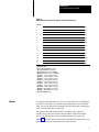
You must allocate two blocks of memory within the PLC’s data table for
use by the interface module. The module requires this memory for block
transfer read and write files.
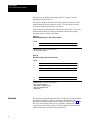
The maximum length of the block transfer write file is 64 words. Set the
length of the write file to the default value of 00.
The maximum length of the block transfer read file is 64 words. Set the
length of the read file to 00 which allows the module to determine the
proper file length.
You will also need to allocate portions of the data table for the files related
to the module’s commands.
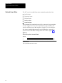
Set Control Command
This command enables the PLC to:
specify the number of loop controllers attached to the communication
link
select either the auto mode or the manual mode
specify either a remote or local set point
enter the value of a new set point or output
acknowledge alarms
The PLC sends the command to the module via block transfer instructions.
The module interprets the command and sends the appropriate message out
to the loop controllers over the RS-485 serial link.
Important: The loop controller must be in the manual mode to change an
output. The loop controller can be in either the automatic or manual mode
when changing a set point.
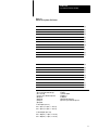
Set control setpoint/output values are four-digit BCD numbers which
represent percent of scale. These values can range between -2.0 and +
102.0. Negative values have their most significant bit set.
7