1
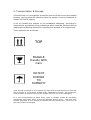
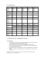
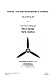
SERVE OVER COUNTERS
MANUAL OF INSTRUCTIONS FOR USE AND INSTALLATION
Table of Contents
1. General Safety Instructions
2. Transportation & Storage
3. General Information & Technical Data
4. Directions for Installation & Use
5. Maintenance & Troubleshooting
Brought to you exclusively by
1. General Safety Instructions
Below is a list of good practice instruction to ensure the safe use and
handling of this appliance. Failure to do so may result in irreparable
damage to the unit or physical harm to the user
•
Ensure the plug and the socket are in good working order before
connecting the supply
•
Ensure the voltage and frequency of the mains supply correspond
with the information on the rating plate
•
Disconnect the unit from the mains power supply before any
cleaning or maintenance
•
Do not touch electrical parts with wet hands
•
Always use suitable tools for the parts to be handled
•
Avoid letting any tool come into contact with any moving parts
(fans etc)
2. Transportation & Storage
A forklift truck or a transpallet should be used to lift and move the packed
product, paying particular attention that the weight is evenly balanced to
reduce the risk of tipping.
A set of symbols are printed on the cardboard packaging, according to
international regulations giving indications which could be observed during
loading and unloading operations, handling and storage of the appliances.
These symbols are as follows:
TOP
FRAGILE
Handle With
Care
DO NOT
EXPOSE
TO
HUMIDITY
Units should be stored in an enclosed dry place and be protected from dust and
dirt by means of a dust sheet, bubble wrap, cardboard or similar. All precautions
must be taken to prevent the ingress of water into the unit or it’s packaging
It is not recommended to stack these units in storage unless all necessary
precautions have been taken to prevent damage and/or injury. The units may
contain glass and as such should be treated with the utmost care. Failure to do
this may result in breakages.
3. General Information & Technical Data
This appliance is designed for the storage and display of previously cooked or
packaged food and drinks. Serveover counters such as this are suitable for
premises of all sizes and can be multiplexed to create longer display areas. The
unit comprises of a lower storage area and an upper glass display area. Both
areas are separated by the deck but are controlled by one refrigeration system.
3.1 Detailed Description
The basic parts of the appliance can be seen on the schematic at the rear of this
manual and will correlate directly with the following key:
1. Body – The body is made of galvanized steel with a PVC Cover and
has 50mm thick polyurethane insulation. Both cooling sections are
contained within the body.
2. Side Panels – These are designed to close off the cabinet at either
end, they may be removed in order to join onto another cabinet. The
ends are made from vacuum formed polystirol and are filled with
40mm thick polyurethane insulation.
3. Doors – The doors on the appliance are for sealing the lower storage
section when not in use. The door is constructed of galvanized steel,
coated with a PVC Lacquer and is filled with 30mm thick polyurethane
insulation. It also has a magnetic edge around the door for sealing.
4. Top – The top is mounted on the rear of the appliance and may be
used for serving or preparing the goods.
5. Glass Screen – Fully tempered glass surrounds the outer edge of the
counter and encloses it into a showcase
6. Display Light – Illuminates the showcase area and consists of a
fluorescent tube, electric power unit and a power switch.
7. Rear Doors – 3mm plexiglass sliding doors which are removable and
sliding.
8. Shelf – Mid display shelf, located to the front of the glass.
Constructed from flat tempered glass 8-12mm thick, this may be used
to display smaller items or may be removed.
9. Screen – Located toward the front of the deck, this is made of 6mm
thick tempered steel and is designed to prevent fogging and lowers the
loss of heat through the front glass
10. Evaporator – This is a pipe-lamella heat exchanger and is part of the
refrigeration system. There is a dish underneath to collect condensate
water
11. Deck – This is meant for displaying the products on and is constructed
from sheet stainless steel.
12. Chassis – This is a three dimensional welded structure, designed to
support the weight of the appliance
13. Compressor – consisting of a hermetic cooling compressor, an air
cooling pipe-lamella condenser, axial motor fan and a filter dehydrator
of refrigerant gas.
14. Power Switchboard – Control Unit for the power supply
15. Evaporation Tray – Designed to collect condensate water to be
evaporated by the heat of the compressor
16. Power Flex – Electrical supply power lead
17. Control Panel – Main control unit for the operation and regulation of
temperature.
3.2 Technical Data
Model
Dimensions
Length
Width
Height
Length excl.
Side Panels
Display Area
of the Shelf
Volume of
Storage
Space
Weight of
Cabinet
Weight of
Goods Per 1
Shelf /
Number of
Shelves
Voltage and
Frequency
Temperature
in Refrig.
Space
Total Rated
Input
Rated Input
of Lights
Power
Consumption
Refrigerant
Quantity
R404A
Unit
OMEGA100
OMEGA130
OMEGA160
OMEGA200
mm
mm
mm
mm
1000
920
1250
980
1250
920
1250
1170
1630
920
1250
1550
2020
920
1250
1940
M2
0.52
0.65
0.87
1.09
Dm3
164
205
276
340
kg
-
123
154
182
kg
45/2
45/3
45/4
45/5
Volt/Hz
Class
°C
220-230V
/50HZ
3M2
+1 +7
220-230V
/50HZ
3M2
+1 +7
220-230V
/50HZ
3M2
+1 +7
220-230V
/50HZ
3M2
+1 +7
Watt
314
358
462
532
W
14
21
28
28
KWh/24h
-
-
-
-
kg
-
-
-
0.380
4. Directions for Installation & Use
4.1 Unpacking
•
•
•
•
•
The appliance should be unpacked immediately to check it is intact
and has suffered no damage during transit.
Any damages should be reported immediately to the carrier
Do not use sharp tools to cut the cardboard and this may damage
the underlying steel panels.
Assemble the feet or alternatively, the fixing brackets of the marble
case
Level the appliance by tightening or unscrewing the bottom part of
the feet
Remove the PVC protective film from the interior and exterior walls,
avoiding the use of metal tools
4.2 Putting Into Operation
To begin the simple process of putting the machine into operation, begin by
setting the main switch on the control to I position. The light on the control
panel should begin to flash. After approximately 2 minutes, the compressor and
the condenser fan should start automatically and the cooling process begins.
Once the appliance has reached the desired temperature, the probe will activate
and and stop the cooling operation, until such time as the temperature falls out of
the required range, upon which, the compressor will start again to regulate the
temperature. Once the cabinet has reached the desired temperature, you may
begin to load the appliance with stock, do NOT load the unit until it has reached
the desired temperature as this may restrict airflow and increase the amount of
energy required to cool.
5. Maintenance & Troubleshooting
Routine Cleaning
Before putting into operation, all parts of the cabinet must be cleaned. For the
interior of the cabinets, a solution of neutral detergent and warm water is
recommended using a moistened cloth. Dry both the interior and exterior of the
cabinet with a soft dry cloth. Do NOT use harsh abrasive detergents or cleaning
materials such as scourers, wire wool etc. Use extra caution when cleaning
moving parts with sharp edges such as evaporator, condenser etc and always use
protective gloves.
Cleaning of Condenser
For improved performance, clean the condenser at least once a week. Before
beginning, ensure the unit is disconnected from the power supply then proceed as
follows:
•
•
Unscrew and remove protective grill
Remove the dust deposited on the front surface of the condenser using
a soft brush and vacuum cleaner. When complete, replace grill and
screw securely
Cabinet Not in Use
During periods of inactivity, remove the products from the cabinet and follow
these instructions:
•
•
•
Disconnect the unit from the power supply, ensuring all switches are
set to OFF
Carefully clean the unit as described above
Cover the cabinet with a cloth or cover that allows air circulation
around the cabinet.
Troubleshooting
The causes of malfunction are often due to problems that can easily be resolved
on site. Check the following points, according to the problem encountered, and
carry out the corresponding fix before calling technical support.
1. The Refrigeration Unit Does Not Start
•
•
Switch to the OFF position and switch back ON again, the unit should start
again after 2 minutes approximately.
Check unit is correctly connected to the power supply
2. The Unit Does Not Cool Sufficiently
•
•
•
Ventilate the room and ensure the unit is away from any direct heat
sources
Clean the Condenser
There may be insufficient refrigerant gas, or the condenser fan may have
stopped. In these instances, contact technical support
3. The Unit Does Not Stop Cooling when It Reaches Temperature
•
•
This may be a broken sensor, contact technical support
This may be a faulty thermostat, contact technical support
4. The Unit is Excessively Noisy
•
•
•
Ensure the unit has been sited on a flat and level surface
Check for any loose screws, nuts or bolts
Move unit away from any other units that may be in contact
If any of the above fail to resolve the problem, contact your technical support
centre quoting serial number, model number and nature of fault
For spare or replacement parts, scan the QR code below with your smartphone or
reader. Alternatively, visit www.pentlandparts.co.uk
www.pentlandwholesale.co.uk
Illustration
Below is an illustration of the counter as described in Section 3