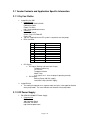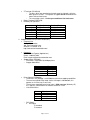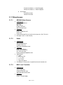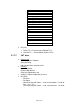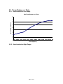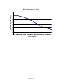
1
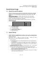
Hai Chiang, Chris Tasker, and Rick Presley
Sputtering Utility Program (SUP) User’s Manual – v1.5
April 22, 2005
General System Usage
1.0
•
•
•
•
•
•
1.1
•
•
General Info and Precautions
There is no interlock that prevents the z-translator from moving into an extended
sputter gun, it is the responsibility of the operator to ensure that this does NOT
happen.
When loading or removing a substrate, take care not to scratch the sealing
surfaces on the load lock.
The deposition angle should only be varied 60° (in either direction) from the vertical
position. There are two vertical positions, 0 and 180°.
Adjustment of the angle of incidence should go in the positive direction, i.e. 0 to 180°
rather than 360 to 180°.
Vacuum gauge setup
Location
Setpoint
Load Lock (TC1)
3
1 mTorr
Foreline (TC2)
2
100 mTorr
Chamber (Capacitance Manometer) 1
100 mTorr
After using the system, it should be left in the following state:
1. Guns/shutter retracted.
2. Z-translator extended.
3. 1” Translator extended
4. Load lock isolation valve closed.
5. Turbo isolation valve open.
6. Rough valve closed.
System Startup
System startup can vary depending on the state the system is found. Assuming that the
system is found at atmosphere and all valves/relays are closed, the following startup
procedure would hold.
Administrative access is required to startup the system.
Contact the system
administrator, Chris Tasker ([email protected]), for assistance.
1. System verification
Verify that the control system (DIO input/output board, vacuum gauge controllers,
etc.) is powered.
Check that the RS-232 cable for the stepper motor controller is plugged into the
back of the PC. Leaving the RS-232 unplugged can cause the control program
to stall or react extremely slowly.
2. In the control program, enter the “System Startup/Shutdown” area. A login prompt
will appear when the button is clicked.
3. Turn on the chillers and dry mechanical pumps by performing the following tasks:
Energize the 120 V coolant relays by clicking the “Coolant Relay” button. The
color of this button should change from red to green.
Open the cooling water supply/return valves.
Provide 120V to the backing and load lock pumps by clicking on the “Backing
Pump” and “Load Lock Pump” buttons.
Page 1 of 18
4.
5.
6.
7.
8.
9.
10.
11.
The chillers and dry mechanical pumps are located in the storage closet. Turn
on the chillers. In the current setup, there are 2 chillers, one supplying cooling
water to the system and the other supplying cooling water to the dry mechanical
pumps.
The load lock pump has an additional RuVac in series. First, turn on the load
lock pump (which is the left control box), wait ~30 seconds, and then turn on the
RuVac. Turn on the backing pump.
Before opening the foreline, complete the following tasks:
Verify that the Turbo Pump blades are not spinning by placing your hand on top
of the pump.
Verify that the regulator supplying nitrogen to the leak/vent valve of the turbo
pump is set to 0.5 Bar.
If the blades are not spinning, vent the turbo pump. Venting the pump will
provide positive pressure, preventing backflow from the backing pump once the
foreline is open.
If the blades are still spinning, wait until they stop (if the pump is isolated, it can
take several hours for the blades to spin down from full rpm, which is 38k for this
particular pump.) before venting the pump.
Open the foreline valve. Wait for the foreline interlock to engage before proceeding
any further; the interlock will engage approximately 30 seconds after the valve is
opened. This wait will give sufficient time for the foreline pressure to fall below the
setpoint, which is currently set at 100 mTorr.
To rough the chamber, complete the following steps:
Verify that the chamber pressure (cap man) and load lock pressure are in the
same relative state. The VAT valves that are used for load lock and turbo pump
isolation have a maximum differential pressure that can be present when opening
and closing the valve. (1 bar when closing)
Open the load lock isolation valve.
Open the roughing valve.
Allow the chamber to rough to 50 mTorr. To check the chamber pressure, hit
the “CHAN” button on the Multigauge Controller until you reach the capacitance
manometer (a flashing “1” will appear towards the lower right).
Close the load lock isolation valve, then roughing valve.
Throttle the turbo isolation valve and check the foreline pressure. Allow the foreline
pressure to stabilize below 5 mTorr and then open the turbo isolation valve.
Start the turbo molecular pump. This is done by:
Closing the turbo pump “interlock” switch then the “start” switch.
The blades should start to spin; the turbo controller display should say “Soft
Startup”. Soft startup slowly increases the rotational speed of the blades; it will
take approximately 40 minutes to reach full rpm.
After several minutes, it should be it should be safe to turn on the BA Ionization
gauge. To do this, hit the “CHAN” button on the Multigauge Controller until the BA
Ion Gauge channel is showing, then hit the “EMIS” button.
Calibrate the z-translator
Click on “Calibrate Z-Translator”.
Ensure that nothing the guns/shutter are fully retracted. First, look in the
chamber with a flashlight. Retract the guns if needed. Slightly extend the
shutter, then retract it. Do this on both sides of the chamber. This verifies that
the shaft has not “detached” from the magnetic coupler.
Click on “Extend Z-Translator”.
Allow the z-translator to move to the end of its stroke, i.e. allow the z-translator to
extend until it hits the limit switch.
Reset the stepper controller.
Click on “Retract Z-Translator”; this should move the z-translator to the load
position.
Extend the 1” translator
Page 2 of 18
12. Enter applicable comments and then click the “OK” button. This will exit the
Startup/Shutdown area, and return the program to the main page.
13. Allow the system to pump down to base pressure, ~1E-7.
Page 3 of 18
1.2
Sputter a Film
1.2.1 Log User/Sample Information
1. Input the required information
Choose a Sample ID; this can be anything that you choose.
Choose the deposition gun/material:
o Gun numbering system: Stand at the end of the system, facing the
load lock. Guns L-1 and L-2 are located on the left hand side (L-1 is
the gun on the left flange that is closer to the turbo pump). Guns R-1
and R-2 are located on the right hand side. Currently Guns L-2 and R2 are not installed
2. Move onto the next page by clicking “Continue”.
1.2.2 Load Substrate
1. Before proceeding, verify that the guns/shutters are fully retracted as described in
section 1.1.10.
2. Log the system base pressure.
3. Turn off the ionization gauge; the gauge uses a tungsten filament and should be
allowed to cool for approximately 5 minutes.
4. Set your processing temperature. The temperature may overshoot and need several
minutes (to half an hour) to stabilize.
5. Load substrate(s) by completing the following:
Vent the load lock.
Retrieve the substrate holder and mount your substrate(s).
Load the substrate holder. When loading or removing a substrate, take care not
to scratch the sealing surfaces.
Secure the load lock door by LIGHTLY tightening screw knob; once the rough
valve is open, the door should close tightly and make a good seal, so there is no
need to overtighten the door knob.
Rough the load lock to 1 mTorr.
6. Close the turbo isolation valve and flow an inert gas to bring the chamber to 10
mTorr. To flow a gas, open the MFC shutoff valve, then flip the appropriate channel
to “On”. Depending on the programmed flow rate, the pressure may rise rapidly, so
be ready to close the shutoff valve. Close the shutoff valve, then turn gas flow off.
7. Transfer substrate(s) from the load lock to the deposition chamber by completing the
following:
Open load lock isolation valve.
Set the shim in place and extend the load lock translator. The shim will provide
the clearance needed to successfully retract the z-translator.
Retract 1” translator
Remove the shim
Fully extend the load lock translator.
Look in the chamber to verify that there is spacing between the substrate holder
and the load lock translator. Additionally, verify that there is sufficient spacing
between the heater and the load lock translator.
Move the z-translator to “pre-load” position
Wait for the z-translator to stop moving. Look in the chamber to verify that the
load lock translator can clear the substrate holder, then retract the load-lock
translator.
8. Close load lock isolation valve
9. Close the rough valve
Page 4 of 18
10. Throttle the turbo isolation valve until the capacitance manometer is out of range (it
will display “---“. Then, fully open the turbo isolation valve.
11. Retract the z-translator. If you did not verify that the guns/shutters are fully retracted,
do so before retracting.
12. Once the z-translator has stopped moving, set angle of incidence (±60° from
vertical).
13. Wait until the system has reached base pressure, then hit “Continue”. Note: The
control program will check that the load lock isolation valve must be closed, the ztranslator must be retracted, and the 1” translator must be retracted before allowing
you to continue.
1.2.3 Strike Plasma/Program Stepper
1. Determine a valid throw distance and angle of incidence.
Throw distance is the distance from the face of the gun to the center of the
chamber.
The graph located in the Appendix shows minimum throw distance as a function
of theta.
Diagram of substrate assembly:
Theta
Claw
Heater
1.5”
¢
Substrate Holder
1”
3.8125”
(Not to scale)
Theta can be adjusted ±60° from the vertical position (note that the vertical
position is shown in the diagram). If either gun L-1 or L2 is being used, theta can
be adjusted from 60° to 0° and 0° to 300° (0° is vertical). If gun R-1 is being
used, theta can be adjusted from 120° to 240° (180° is vertical).
Verify that the throw distance and the angle of incidence, set earlier, are valid.
2. Extend the shutter, then the gun that will be used for this deposition.
3. To strike a plasma, complete the following:
Verify that the gun cooling water is flowing.
Verify that the rf cable is connected to the correct gun.
Throttle the turbo isolation valve.
Open the shutoff valves for the MFC’s which will be used.
Adjust the flow setpoints if needed.
Page 5 of 18
4.
5.
6.
7.
8.
9.
Turn “On” the appropriate channels. ALWAYS flow the least reactive gas first.
Adjust the throttle valve to the appropriate processing pressure.
Set the striking power. Then turn “On” the rf power. Note: Many of the targets
used in the lab are ceramics. Thus, the recommended striking powers are 40
and 80 W for the 2 and 3 inch guns, respectively.
Once the plasma is ignited, monitor the dc bias and plasma characteristics.
Allow the dc bias to stabilize, then increase the power to your sputtering power at
a rate of 5 and 10 W/min for the 2 and 3 inch guns, respectively. Slowing
increasing the power on ceramic targets minimizes the possibility of cracking the
target.
If the target is new, it requires a “burn-in” run. This can range anywhere from 6
to 12 hours depending on where the target was obtained. Targets that are
fabricated “in-house” typically require longer burn-in times.
Allow the target to presputter. When presputtering, place the shutter should be
placed in front of the target; this will help keep the sputter chamber clean.
Log your sputter parameters while your target is presputtering.
Program stepper controller.
Note that the scale has been reversed, fully extended is 0”, not 30” as the ztranslator ruler says. Thus, when “retracting”, the position is increasing.
Rotate the shutter and move it out of the way.
Move your substrate into place.
Hit the “Continue” button once sputtering is complete.
1.2.4 Retrieve Substrate
1. Extinguish the plasma by completing the following:
Retract the z-translator
Move the shutter back in front of the gone.
Slowly decrease the RF input power to the recommended striking power if you
are using a ceramic target. Unless you are sputtering at the recommended
striking powers, NEVER turn off the power without allowing it to cool down. Use
the same rates for increasing/decreasing rf power.
Turn off the rf power.
Retract the sputter gun and shutter.
2. Turn off heater.
3. Remove your substrate(s) by completing the following:
Set angle of incidence back to 0.
Look in the chamber to ensure there are no obstructions.
Extend the z-translator to the “pre-load” position.
Close the turbo isolation valve and leak up to 10 mTorr.
Rough the load lock.
Open load lock isolation valve.
Extend Load lock translator; the shim should not be used this time. If the load
lock translator hits the substrate holder, the angle of incidence may need to be
adjusted by a few degrees for proper unloading.
Once the load lock translator is in place, extend the z-translator.
Extend 1” translator once the z-translator has stopped moving.
Retract load lock translator
4. Close load lock isolation valve
5. Close the rough valve.
6. Throttle the turbo isolation valve, then fully open it.
7. Allow the substrate to cool in the load lock
8. Retrieve substrate
Loosen the door knob on the load lock.
Page 6 of 18
Vent the load lock.
Retrieve substrate. Caution: Do not scratch the sealing surface of the load lock.
Additionally, if you used substrate heat, you may want to use insulated gloves!
9. Return the substrate holder to the load lock.
10. Rough the load lock (close the rough valve once the load lock is below 1 mTorr).
1.3
Changing Targets
1. Bring the chamber and load lock to the same state.
2. Close Turbo Iso valve. Note, the isolation valve will automatically throttle itself, wait,
and then fully close.
3. Open Load Lock Iso
4. Vent chamber
Remember to loosen the doorknob before venting.
Close the vent valve once the chamber has reached atmospheric pressure.
5. Change the target
Remove all but two bolts on the appropriate 6” conflat flange.
Dismount the flange from the chamber. Hold the base of the gun (near the
flange), and move the flange in an up/down motion until the seal with the gasket
breaks. Note: Do NOT hold the shaft of the gun.
Remove the old target and mount the new one.
o Currently, only US Mighty Mak guns are used on this system.
o Make sure that there is a thin layer of thermal compound on the cathode.
o There are no screws needed; the magnet/keeper will hold the target in
place.
Remove and discard the used gasket. Gaskets are NEVER to be reused.
Clean the knife edge on the 6” flange and the chamber with a Kimwipe and some
methanol.
Obtain a new gasket and visually inspect the gasket for defects and cleanliness.
Blow the gasket off with nitrogen.
Mounting the flange. First, place the copper gasket on the 6” flange. Ensure that
it is seated properly, then slowly move the flange towards the chamber.
Remember, all knife edges are sealing surfaces!! Once the flange is seated on
the chamber, line up the leak check grooves. Hold the flange there and install
four bolts finger-tight. You can then let the flange loose and finish installing all
the bolts. Finally, torque the flange. A 6” flange is tighten to 16 ft-lb.
6. Open Rough Valve and allow the system to pump below 50 mTorr.
7. Close Load Lock Iso Valve (the rough valve should automatically close)
8. Throttle Turbo Iso Valve and allow the foreline to stabilize.
9. Open Turbo Iso Valve
1.4
Changing Gas Cylinders
1. Log any gas changes and update the labeling on the MFC box appropriately.
Page 7 of 18
Application Notes
2.0 DIO Card
Steps for programming (for PCI-7248 pgs. 36-40, 49-59, 66-71, 74)
o Initialize the card
o Register_Card(PCI_7248, 0)
o Setup the ports.
DIO_PortConfig(card, i * 5 + Channel_P1A, OUTPUT_PORT)
DO_WritePort(card, i * 5 + Channel_P1A, &HFF)
Port Info
Port
Signal
P1A0
P1A1
P1A2
P1A3
P1A4
P1A5
P1A6
P1A7
P1B0
P1B1
P1B2
P1B3
P1B4
P1B5
P1B6
P1B7
P1C0
P1C1
P1C2
P1C3
P1C4
P1C5
P1C6
P1C7
Coolant Temp
Coolant Flow
Leak (Water)
Comp Air
Turbo Fault Signal
Backing temp warn
Cap. Man.
Foreline TC
Ld Lk TC
Idle State
Port
Signal
1
1
1
1
0
1
1, &
1, &
1
P2A0
P2A1
P2A2
P2A3
P2A4
P2A5
P2A6
P2A7
P2B0
P2B1
P2B2
P2B3
P2B4
P2B5
P2B6
P2B7
P2C0
P2C1
P2C2
P2C3
P2C4
P2C5
P2C6
P2C7
Turbo System Override
+
Generator Interlock
1” Extend/retract relay
Ld Lk Valve Relay A
Ld Lk Valve Relay B
Turbo Valve Relay A
Turbo Valve Relay B
Coolant Relay A
Coolant Relay B
Ld Lk Vent Relay
MFC DCV Power
Foreline Valve
Backing Pump
Load Lock Pump
Ld Lk Trans Top of Stroke
Ld Lk Iso Valve Closed
Gun Retracted
Shutter Retracted
Critical OR Gate
Backing Oil Pressure
Backing Temp Alarm
Backing Motor Temp
Load Temp Warn
Load Oil Pressure
Load Temp Alarm
Load Motor Temp
1
1
1
1
1
1, &
1
1
1
1, &
1
1
Legend: In/Out/Critical Signals
* Interlocked signal
+ Damaged Output Port
& Special Startup/Shutdown Considerations
Code
Additional Signals
P3A0
P3A1
P3A2
P3A2
P4A0
P4A1
Z extended
Z retracted
Extend Limit Switch
Retract Limit Switch
Extend Z translator
Retract Z translator
Motor
Motor
Motor
Motor
Motor
Motor
Commands
DI_ReadLine
DI_ReadPort
DIO_PortConfig
DO_ReadLine
DO_ReadPort
DO_WriteLine
DO_WritePort
Register_card
Release_card
Page 8 of 18
*, P1B4, P2C0
*, P1A7, P2B5
Turbo low speed
Turbo interlock
Interlocks
*, P1B5, P1B6, P1A6
*, P1B5, P1B6, P1A6
*Newly added signal
**Default is the state that the system is “normally” in (already started up)
Useful
o
o
o
o
o
o
o
o
o
*, P3A0, P3A1
*, P1B0, P1B3
*, P1B0, P1B3
*, P1A6, P1A7, P1B4, P2B5
*, P1A6, P1A7, P1B4, P2B5
Rough Valve
Leak Valve
Turbo Start
Source
Stepper
Stepper
Stepper
Stepper
Stepper
Stepper
Interlock
2.1 Vendor Contacts and Application Specific Information
2.1.1 Dry Vac/ RuVac
1. Leybold DryVac 50B
Company Info:
LEYBOLD VACUUM USA INC.
5700 Mellon Road
Export, PA 15632
http:// www.leyboldvacuum.com/
Contact(s):
Name: Ken Arondt
Phone: (724) 327-5700 x551
Email: N/A
120 VAC supplied from the DIO system is required to start the pumps.
DB-9 Connecter
Pin
1
2
3
4
5
6
7
8
9
Signal
Gnd
Motor Temp
24 V
Temp Alarm
Oil Pressure
Temp Warning
8-wire Conductor
Drain
Black
Brown
Red
Orange
Yellow
DIO Signals
o DIO Inputs (Backing and Load Lock Pumps)
Temperature Warning
Oil Pressure
Temperature Alarm
Motor Temp
If all signals are ‘1’, then the pump is operating normally.
o DIO Outputs
Backing Pump (120 VAC supply)
Load Lock Pump (120 VAC supply)
2. Leybold RuVac
The cooling fan operates on a separate motor and spins in the opposite direction
of the pump motor. The arrow indicates the direction of the pump motor.
2.1.2 RF Power Supply
1. ENI OEM-25A 2500W RF Power Supply
Company Info:
ENI Products
100 Highpower Road,
Rochester, NY 01887
http://www.enipower.com/
Page 9 of 18
Contact(s):
Name: Vitaly
Phone: (585) 427-8300
Email: N/A
Name: Billy (Technician)
Phone: (585) 214-0316
Email: N/A
Name: Debbie Thibault (Sales)
Phone: (585) 292-7478
Email: [email protected]
2. ENI MW-25D RF Matching Network
2.1.3 Sputter Guns (US Inc. Mighty Mak L200A01L/L300A01L)
Company Info:
Us Inc.
6280 San Ignacio Ave. Suite E
San Jose, CA 95119-1365
http://www.us-incorp.com
Contact(s):
Name: Todd Johnson
Phone: (408) 363-6909
Fax: (408) 363-6996
Email:
2.1.4 Turbo Molecular Pump (Varian TV1001 Navigator)
Company Info:
Varian Electronics Manufacturing - Rocklin
3715 Atherton Road
Rocklin, California 95765
http://www.varianinc.com
Contact(s):
N/A
100 mTorr cross-over pressure. Since the dry-vac/roots blower stack pumps so
quickly, we will use 1E-4 as the crossover pressure.
10 sccm nitrogen leak used to keep particulates and corrosive materials away
from the bearings of the turbo pump.
Turbo Pump Female DB-9 (Input)
Pin
Signal
8-wire
2-wire
Conductor
conductor
1
Start
Black
2
Low Speed
Brown
3
Interlock
Red
4
Turbo
Black
Override
5
6
Start (Com)
Orange
7
Low Speed
Yellow
(Com)
8
Interlock
Green
(Com)
Page 10 of 18
9
Turbo
Override
(Com)
White
Turbo Pump DB-15 (Output)
Pin
Signal
1
2
3
4
5
6
7
8
Fault
9
10
11
12
13
14
15
Fault (+24 V)
2-wire Conductor
White
Black
DIO Signals
o DIO Inputs
Turbo Fault Signal (1 = fault present, 0 = no fault)
o DIO Outputs
Turbo System Override (1 = turbo pump overridden)
2.1.5 Vacuum Chamber (Nor-Cal)
Company Info:
Nor-cal Products
http://www.n-c.com
Contact(s):
Name: Steve Greuel (Products Manager), Monica (Sales)
Phone: (530) 842-9130
Fax: (530) 842-4457
Email: [email protected]
2.1.6 Z-translator
1. Z-translator Unit (McAllister Technical Services)
Company Info:
McAllister Technical Services
West 280 Prairie Avenue
Coeur d'
Alene, ID 83815
http://www.mcallister.com/
Contact(s):
Name: Bob McAllister
Phone: 1-800-445-3688
Fax: (208) 772-3384
Email: [email protected]
Page 11 of 18
Z Translator (ZA-450-30)
o The brass drive-gear attached to the lead screw has 20 teeth, while the
worm gear has 4 starts. This equates to a gear ratio of 5:1 between the
motor shaft and lead screw.
o The z-translator travels .1 inches per revolution of the lead screw.
Rotary Platform (DPRF-450)
Divide-by-10 Z-positions
Gun L1 Start
Gun L1 Finish
Gun R1 Start
Gun R2 Finish
Retract
Load position
Position (inches)
23.65”
11.65”
20.325”
8.625”
29”
.6875 (11/16)”
Position (Steps)
2,490,000
1,227,500
2,175,000
906,250
68,750
2. Stepper Motor/Driver (Anaheim Automation)
Company Info:
Anaheim Automation
910. East Orangefair Lane,
Anaheim, CA, 92801-1195
http://www.anaheimautomation.com/
Contact(s):
Name: Alfonso Esparza (Applications)
Phone: 1-800-345-9401
Email: [email protected]
Stepper Motor (23D309S)
o The motor is rated at 2.2 V, 4.6A per phase.
o Stepper Motor Wires
Color
Red
Red – White
Green
Green - White
Signal
Phase A+
Phase A Phase B+
Phase B -
Driver/Indexer (DPD60401)
o The driver in this package is a 1-5.5A driver with micro-stepping capabilities.
o The maximum speed of the motor shaft at full torque is 10 revs/sec; this
equates to .2 inches/sec (5 secs/inch).
o The minimum speed without missing steps is 5000 steps/rev (divide-by-25).
At 1 step/sec, it would take 4167 minutes to traverse 1 inch.
o Limit Switch Wires
Color
Orange
Red
Yellow
Green
o
Signal
Limit SW 1
Limit SW 1 Return
Limit SW 2
Limit SW 2 Return
DIO Signals
a. DIO Inputs
Z-extended
Z-retracted
Page 12 of 18
Extend Limit Switch (1 = Switch Engaged)
Retract Limit Switch (1 = Switch Engaged)
b. DIO Outputs
Extend Z-translator
Retract Z-translator
2.1.7 Miscellaneous
2.1.7.1
GRI 2800 Water Sensors
Company Info:
George Risk Industries
GRI Plaza
802 S Elm St
Kimball, NE 69145
http://www.grisk.com/
Contact(s):
Name: N/A
Phone: 1- 800-523-1227
Email: N/A
Purchased through Platt in Corvallis @ 8.42 per unit. (541) 753-1221.
DIO Input: Leak (1 = Leak Present)
2.1.7.2
Heater
Company Info:
Solar Products
228 Wanaque Avenue
Pompton Lakes, N.J.
http://www.solarproducts.com/
Contact(s):
Name: John Schafer
Phone: (973) 248-9370
Fax: (973) 835-7856
Email: [email protected]
Specifications:
o 110 V
o 60 W/ Sq. Inch
o 7” x 7” Face
o 2.25” Thick
o High Purity quartz
Coil direction is critical; coils run parallel to the main chamber axis.
2.1.7.3
MDC 1-inch Translator
Company Info:
MDC
23842 Cabot Blvd.
Hayward CA 94545-1661
http://www.mdc-vacuum.com/
Contact(s):
Name: N/A
Phone: 1-510-265-3000
Page 13 of 18
Email: N/A
2.1.7.4
MKS Baratron Capacitance Manometer
Company Info:
MKS, Pressure Measurement & Control Products
Six Shattuck Road
Andover, Massachusetts 01810
United States
http://www.mksinst.com/
Contact(s):
Name: N/A
Phone: 1-800-227-8766
Fax: (978) 975-0093
Email: N/A
2.1.7.5
Thermionics Rotary Linear Feedthroughs
Company Info:
Thermionics Vacuum Products
231-B Otto Street
Port Townsend, WA 98368
http://www.thermionics.com/index.shtml
Contact(s):
Name: Tom Howard
Phone: 1- 800-962-2310
Fax: (360) 385-6617
Email: [email protected]
2.1.7.6
Varian Multi-gauge Controller
Company Info:
Varian Electronics Manufacturing - Rocklin
3715 Atherton Road
Rocklin, California 95765
http://www.varianinc.com
Contact(s):
Name: N/A
Phone: N/A
Email: N/A
The original manual sent with the Multi-Gauge was not correct, it did not have
correct datasheet for the set point board installed in the Multi-Gauge (L8727302).
Set Point DB25
o SP1 – Cap Man
o SP2 – Foreline TC
o SP3 – Load Lock TC
Pin
1
2
3
Signal
8-wire Conductor
Page 14 of 18
4
5
6
7
8
9
10
11
12
13
14
15
16
17
18
19
20
21
22
23
24
25
SP3-NO
SP3-C
SP2-C
Violet
Yellow
Red
SP1-C
Black
SP2-NO
Orange
SP1-NO
Brown
DIO Inputs
o Cap. Man (1 = Pressure below set point of 1E-1)
o Foreline TC (1 = Pressure below set point of 1E-1)
o Load Lock TC (1 = Pressure below set point of 1E-3)
2.1.7.7
VAT Valves
Company Info:
Thermionics Vacuum Products
231-B Otto Street
Port Townsend, WA 98368
http://www.thermionics.com/index.shtml
Contact(s):
Name: Tom Howard
Phone: 1- 800-962-2310
Fax: (360) 385-6617
Email: [email protected]
70-80 psi is required to open/close the valve.
DIO Signals
o DIO Inputs
Load Lock Iso Closed (1 = Valve Closed)
o DIO Ouputs
Ld Lk Valve Relay A/B (Closed
A=0, B=0; Intermediate
Open
A= 1, B=1)
Turbo Valve Relay A/B (Closed
A=0, B=0; Intermediate
Open
A= 1, B=1)
Page 15 of 18
A=1, B=0;
A=1, B=0;
General System Usage
3.0 Chamber Dimensions referenced to the Z-translator
Load
Lock
Turbo Pump
¢
¢
L-1
L-2
3.015”
12”
14”
8”
6”
7”
Z-Position
17 3/8”
11 3/8”
3/8”
Note: The numbers referenced above are referenced relative to the “physical” position of the ztranslator. There is an addition 3/16” offset required get the position of the center of the wafer;
11 9/16” for L-2 and 17 9/16” for L-1.
3.1 Maximum Throw Distance
¢
Gun L-1
Gun R-1
Max Throw
Distance =
8.215”
Max Throw
Distance =
7.775”
3.91”
4.35”
11” + 1.125”
11” + 1.125”
Page 16 of 18
3.2 Throw Distance vs. Theta
3.2.1 Guns Installed on Left Flange
Min Throw Distance vs. Theta
4.5
4
Min. Throw Distance
3.5
3
2.5
2
1.5
1
0.5
0
0
10
20
30
40
50
Theta (Degrees)
3.2.2 Guns Installed on Right Flange
Page 17 of 18
60
70
80
90
Min. Throw Distance vs. Theta
4.5
Min. Throw Distance (Inches)
4
3.5
3
2.5
2
1.5
1
0.5
0
90
100
110
120
130
140
Theta (Degrees)
Page 18 of 18
150
160
170
180