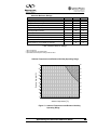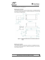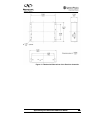
1
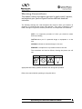
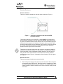
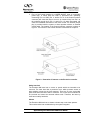
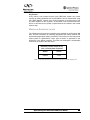
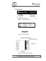
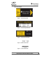
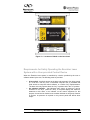
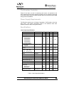
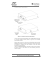
Excelsior-488
488nm Solid State Laser
User’s Manual
This laser product is intended to be sold to a
manufacturer of OEM products for use as a
component (or replacement thereof) in those
products. As such, this product is exempt from
performance standards of United States Code of
Federal Regulations, Title 21, Chapter I – Food and
Drug Administration, Department of Health and
Human Services, Subchapter J – Parts 1040.10 (a),
(1)
Spectra-Physics
1335 Terra Bella Avenue
Mountain View, CA 94043
Revision 1.2
Oct 2008
Preface
This manual contains information you need in order to safely install and operate your
Excelsior-488 laser. An Excelsior-488 system consists of a laser head that produces
blue light (488nm) and a controller, connected by an umbilical cable.
Excelsior is designed to be an OEM product, and all power and command signals are
intended to be provided by a master system to the laser through the controller.
A brief description of the contents of each of the chapters is provided below.
Chapter 1, “Introduction”, contains a brief description of this laser system and its
components.
Chapter 2, “Laser Safety,” is required reading before the system is installed and
operated. The Excelsior lasers are Class IIIb devices and, as such, emit laser radiation
that can cause permanent eye damage.
Chapter 3, “System Description,” contains a short section on the operating principles
of the laser, followed by a more detailed description of the Excelsior laser’s
specifications.
Chapter 4, “Installation and Operation,” describes the procedures and requirements for
first installing and then operating the laser.
Chapter 5, “Troubleshooting and Service,” will help guide you to the source of any
problems with the laser. Do not attempt repairs yourself while the unit is still under
warranty; instead, report all problems to Spectra-Physics for warranty repair.
“Customer Service” in this chapter gives information on service calls and warranty
issues.
Chapter 6, “Warranty and Compliance”, summarizes the warranty and associated
conditions and provides information regarding the procedures for laser return. This
chapter also summarizes the standards to which the lasers comply.
Every effort has been made to ensure that the information in this manual is accurate.
All information in this document is subject to change without notice. Spectra-Physics
makes no representation or warranty, either expressed or implied, with respect to this
document. In no event will Spectra-Physics be liable for any direct, indirect, special,
incidental or consequential damages resulting from any defects in this documentation.
Finally, if you encounter any difficulty with the content or style of this manual, or
encounter problems with the laser itself, please let us know.
Thank you for your purchase of a Spectra-Physics laser.
Spectra-Physics Excelsior-488 User Guide
2
Table of Contents
Preface
Warning Conventions
Unpacking and Inspection
Chapter 1:
Introduction
Chapter 2:
Laser Safety
Chapter 3:
System Description
Chapter 4:
Installation and Operation
Chapter 5:
Troubleshooting and Service
Chapter 6:
Warranty and Compliance
Spectra-Physics Excelsior-488 User Guide
3
Warning Conventions
This manual contains information you need to safely install, operate,
and maintain your Spectra-Physics Excelsior-488 laser head and
controller
The following warnings are used throughout this manual to draw your attention to
situations or procedures that require extra attention. They warn of hazards to your
health, damage to equipment, sensitive procedures, and exceptional circumstances.
NOTE is an important procedure of which you should be aware
before proceeding.
CAUTION alerts you of a potential danger to equipment or to the
user.
WARNING indicates an imminent danger to the user.
REMINDER is a helpful hint to procedures listed in the text.
The conventions are listed as follows, showing the picture you will
see.
NOTE
CAUTION
WARNING
REMINDER
Appropriate laser safety eyewear should be worn during laser operation.
Refer to the manual before operating or using this device.
Spectra-Physics Excelsior-488 User Guide
4
Unpacking and Inspection
Unpacking Your Laser
Your Excelsior laser was packed with great care, and its container was
inspected prior to shipment—it left Spectra-Physics in good condition. Upon
receiving your system, immediately inspect the outside of the shipping
container. If there is any major damage (holes in the container, crushing, etc.),
insist that a representative of the carrier be present when you unpack the
contents.
Carefully inspect your laser system as you unpack it. If any damage is evident,
such as dents or scratches on the covers, etc., immediately notify the carrier
and your Spectra-Physics sales representative.
Keep the shipping container. If you file a damage claim, you may need it to
demonstrate that the damage occurred as a result of shipping. If you need to
return the system for service at a later date, the specially designed container
assures adequate protection.
System Components
Two main components comprise an OEM Excelsior laser system:
• Excelsior laser head
• Excelsior controller
Accessories
Included with the laser is a Certificate of Compliance and an accessory kit.
The following accessories are shipped standard with the system:
•1 laser umbilical cable (1.8m)
•1 interlock jumper plug
Spectra-Physics Excelsior-488 User Guide
5
Chapter 1: Introduction
The Spectra-Physics Excelsior-488 laser produces a blue (488 nm) continuous wave
laser beam from a very compact package. These small, rugged solid-state lasers are
especially well suited for applications requiring a low-noise, high-quality, CW visible
beam. Excelsior lasers are intended for OEM integration into master systems.
The Excelsior laser family consists of a number of different lasing wavelengths and
optical powers. All Excelsior lasers deliver efficient, stable light with excellent spatial
mode that is critical for a wide variety of applications. Please refer to the Newport /
Spectra-Physics website for the latest product information.
Excelsior-488 lasers produce single longitudinal mode continuous wave beams of
exceptional wavelength stability and narrow line width, with fixed optical output power,
depending on the model, from 10mW to 100mW. The same controller operates all
Excelsior-488 laser heads. However, Excelsior-488 laser heads and controllers are not
interchangeable with components of Excelsior lasers of other wavelengths.
The laser heads are designed for precision mounting and alignment of the beam,
which, together with the specified bore sighting of the output, simplifies the task of
designing the master optical train, or replacing a laser head in the master system. All
of the optical components are contained within the laser head itself.
The lasers are controlled by the master system by means of analog signals provided
through a connector on the controller and/or via the 5V power supplied to the
controller.
Spectra-Physics Excelsior-488 User Guide
6
Chapter 2: Laser Safety
Follow the instructions contained in this manual to ensure proper
installation and safe operation of your laser.
CAUTION: The Spectra-Physics Excelsior-488 lasers are Class IIIb
lasers as defined by the Federal Register 21 CFR 1040.10 Laser
Safety Standard. The standard requires that certain performance
features and laser safety labels be provided on the product. Images of
the warning labels in place on the laser are shown later in this section.
WARNING: This product produces laser light at 488nm. Diffuse as well
as specular beam reflections can cause severe eye or skin damage.
Residual invisible light at 976nm wavelength might also be present.
The American National Standards Institute publishes a laser safety
standard for users entitled American National Standard for the Safe
Use of Lasers (ANSI Z136.1). Spectra-Physics strongly recommends
that laser users obtain and follow the procedures described in this
ANSI standard. Copies may be obtained from:
American National Standards Institute Inc.
1430 Broadway
New York, NY 10018
or
Laser Institute of America
2424 Research Parkway
Orlando FL 32826
Spectra-Physics Excelsior-488 User Guide
7
Precautions for the Safe Operation of Class IIIb
Lasers
•
•
•
•
•
•
•
•
Wear protective eyewear at all times; selection depends on the wavelength
and intensity of the radiation, the conditions of use, and the visual function
required. Protective eyewear is available from suppliers listed in the Laser
Focus World, Lasers and Optronics, and Photonics Spectra buyer’s guides.
Consult the ANSI and ACGIH standards listed at the end of this section for
guidance.
Maintain a high ambient light level in the laser operation area so the eye’s
pupil remains constricted, reducing the possibility of damage.
Avoid looking at the output beam; diffuse reflections are hazardous.
Establish a controlled access area for laser operation. Limit access to those
trained in the principles of laser safety. Enclose beam paths wherever
possible.
Post prominent warning signs near the laser operating area.
Install the laser so that the beam is either above or below eye level.
Set up shields to prevent any unnecessary specular reflections or beams from
escaping the laser operation area.
Set up a beam dump to capture the laser beam and prevent accidental
exposure
CAUTION - USE OF CONTROLS OR ADJUSTMENTS, OR PERFORMING THE
PROCEDURES DESCRIBED IN THIS MANUAL IN A MANNER OTHER THAN
SPECIFIED MAY RESULT IN HAZARDOUS RADIATION EXPOSURE.
Operating this laser without due regard for these precautions or in a manner that does
not comply with recommended procedures may be dangerous. At all times during
installation, maintenance or service of your laser, avoid unnecessary exposure to laser
or collateral radiation that exceeds the accessible emission limits listed in
“Performance Standards for Laser Products,” United States Code of Federal
Regulations, 21CFR1040.10(d).
Follow the instructions contained in this manual to ensure proper installation and safe
operation of your laser.
Spectra-Physics Excelsior-488 User Guide
8
Safety Devices
Emission Indicator
There is an emission indicator on the laser head, as shown in Figure 1.
Figure 1 – Showing the position of the laser head LED
emission indicator
The emission indicator is a bi-color LED. It glows AMBER (YELLOW) when
electrical power is present in the laser head, and GREEN when laser current
is present. A GREEN indicator means that the laser can emit 488nm light (this
includes the warm-up period of the laser). During the warm-up period, output
power fluctuates as the laser self-calibrates. During this time, the output power
of the laser may briefly exceed the nominal power of the laser. Maximum
emission levels are given later in this section.
The presence of the laser head cable and connector can obscure visibility of
the laser head emission indicator. For this reason it is recommended that the
system integrator set up an additional emission indicator. This can be done
using Pin 14 of the Control Interface. The location of the Control Interface
connector is shown in Figure 2. A description of the function of Pin 14 is given
in Chapter 4.
Remote Interlocks
There are two ways to implement a remote interlock.
1. The 5V DC power supply to the laser may be interlocked. When the power
is removed the laser will turn off. When the power is re-applied, the laser
will restart, beginning with its warm-up sequence. The disadvantage of this
method is that the interlock switch must be rated for the full supply current
of the laser.
Spectra-Physics Excelsior-488 User Guide
9
2. Pin 2 of the Control Interface is a LASER ON/OFF input. It is internally
pulled high, in which state the laser is prevented from operating.
Connecting Pin 2 to GND (Pin 11 and/or Pin 12 of the Control Interface
connector) will cause the laser to turn on. An interlock loop from Pin 2 to
the selected ground pin(s) (Pin 11 and/or Pin 12) when interrupted, will
cause an immediate shut down of the laser current. An interlock jumper
plug is provided with the system to allow operation without an external
control cable. The location of the Control Interface connector is shown in
Figure 2. The function of the Control Interface is described in Chapter 4.
Figure 2: Illustration of features on the Excelsior controller.
Safety Interlock
The Excelsior-488 laser has no covers or panels which are intended to be
removed. The laser head has a protective cover which prevents access to
laser radiation except via the laser aperture. There are no user serviceable
parts inside either the laser head or controller. The covers are not intended to
be removed and cannot be removed without tools. Therefore, the laser by
itself has no safety interlocks.
Shutter
The Excelsior-488 laser has no shutter or beam stop on the laser aperture.
This must be taken into consideration by the system integrator.
Spectra-Physics Excelsior-488 User Guide
10
Key Control
A key control is not provided as part of this OEM laser system. Key control
required by safety standards such as IEC60825-1 can be implemented using
the LASER ON/OFF function of the Control Interface or by interruption of the
5V power supplied to the controller, as described under “Remote Interlocks”
above. In this case the key switch is implemented as one switch in the remote
interlock loop.
Maximum Emission Levels
The following are the maximum emission levels possible for the Excelsior-488
laser. Use this information for selecting appropriate laser safety eyewear and
implementing appropriate safety procedures. These values do not imply actual
system power or specifications. Laser light at 976nm is generated in the
production of the 488nm emission. This infra-red wavelength is substantially
confined to the inside of the laser head.
Maximum possible output at any
time, including fault conditions
488nm
976nm
<180mW
<1mW
Table 1: Absolute maximum emission levels by product nominal output power.
Spectra-Physics Excelsior-488 User Guide
11
Labels
Controller Labels
Figure 3 – Controller main label
Figure 4 – Controller manufacturer/WEEE label
Figure 5 – Serial number label
Figure 6 – Label locations on controller
Spectra-Physics Excelsior-488 User Guide
12
Laser Head Labels
Figure 7 – Laser head top label
Figure 8 – Laser head right side label
Figure 9 – Laser head left side label
Figure 10 – Model number label
Figure 11 – Serial number label
Spectra-Physics Excelsior-488 User Guide
13
Figure 12 – Locations of labels on the laser head
Requirements for Safely Operating the Excelsior Laser
System with a User-provided Control Device
When the Excelsior laser system is controlled by a device provided by the user or
software written by the user, the following must be provided:
•
•
A key switch - that limits access to the laser and prevents it from being turned
on. It can be a real key lock, a removable computer disk, a password that
limits access to computer control software, or a similar “key” implementation.
The laser must only operate when the “key” is present and in the “on” position.
An emission indicator - that indicates laser energy is present or can be
accessed. It can be a “power-on” lamp, a computer display that flashes a
statement to this effect, or an indicator on the control equipment for this
purpose. It need not be marked as an emission indicator so long as its function
is obvious. Its presence is required on any control panel that affects laser
output.
Spectra-Physics Excelsior-488 User Guide
14
Schedule of Maintenance in Accordance with Center for Devices and
Radiological Health (CDRH) Regulations
NOTE: This laser product is intended for OEM use. Therefore, an application has not
been submitted with the Center for Devices and Radiological Health (CDRH) for
compliance review. However it is recommended that the same schedule of
maintenance be followed as that for systems that comply with these regulations. Once
a year, or whenever the product has been subjected to adverse environmental
conditions (e.g., fire, flood, mechanical shock, spilled solvent, etc.), check to see that
all features of the product identified function properly. Also, make sure that all warning
labels remain firmly attached.
1. Verify that opening any safety interlock switch used with the system prevents
laser operation.
2. Verify the laser can only be turned on when the master system key-switch is in
the on position, and that the key can only be removed when the switch is in
the off position.
3. Verify the user-supplied emission indicator provides a visible signal when the
laser emits accessible laser radiation that exceeds the accessible master
system emission limits for Class I1.
4. Verify the time delay between turn-on of the user-supplied emission indicator
and the start of laser emission; it must give enough warning to allow action to
avoid exposure to laser radiation.
5. Verify that when the interlock loop is opened the master system shutter closes
and actually blocks laser radiation emission. If any of the above items fail to
operate as noted and you cannot correct the error, please call your SpectraPhysics service representative for assistance.
Sources of Additional Information
Laser safety Standards
Safe Use of Lasers (Z136.1)
American National Standards Institute (ANSI)
11 West 42nd Street
New York, NY 10036
Tel: (212) 642-4900
Occupational Safety and Health Administration
(Publication 8.1-7)
U.S. Department of Labor
200 Constitution Avenue N. W., Room N3647
Washington DC 20210
Tel: (202) 693-1999
A Guide for Control of Laser Hazards, 4th Edition,
Publication #0165
1
0.39uW for continuous-wave operation where output is limited to 400nm to 1400nm.
Spectra-Physics Excelsior-488 User Guide
15
American Conference of Governmental and Industrial
Hygienists (ACGIH)
1330 Kemper Meadow Drive
Cincinatti, OH 45240
Tel: (513) 742-2020
Internet: www.acgih.org.htm
Laser Institute of America
13501 Ingenuity Drive, Suite 128
Orlando FL 32826
Tel: (800) 445-4200
Compliance Engineering
Canon Communications LLC
11444 W. Olympic Boulevard
Los Angeles CA 90064
Tel: (310) 445-4200
International Electrotechnical Commission
Journal of the European Communities
EN 60825-1 Safety of Laser Products – Part 1:
Equipment classification, requirements and user’s
guide
Tel: +41 22-919-0211 Fax: +41 22-919-0300
Internet: www.iec.ch
Cenelec
35 Rue de Stassartstraat
B-1050 Brussels, Belgium
Tel: +32 2 519 68 71
Internet: www.cenelec.org
Document Center Inc.
111 Industrial Road, Suite 9
Belmont CA 94002
Tel: (650) 591-7600
Internet www.document-center.com
Spectra-Physics Excelsior-488 User Guide
16
Equipment and Training
Laser Safety Guide
Laser Institute of America
13501 Ingenuity Drive, Suite 128
Orlando FL 32826
Tel: (800) 34LASER
Internet: www.laserinstitute.org
Laser Focus World Buyers Guide
Laser Focus World
Pennwell Publishing
98 Spit Rock Road
Nashua NH 03062
Tel: (603) 891-0123
Internet: www.laserfocusworld.com
Photonics Spectra Buyer’s Guide
Photonics Spectra
Laurin Publications
Berkshire Common
PO Box 4949
Pittsfield MA 01202-4949
Tel: (413) 499-0514
Internet: www.photonics.com
Spectra-Physics Excelsior-488 User Guide
17
Chapter 3: System Description
Excelsior Laser Head
The Excelsior-488 laser head consists of two key functional sections. The first
section is responsible for generation of the high power 976nm light and the
second section is where the 976nm photons are converted into the visible,
488nm output. More details of each of these sections are provided below.
976 nm External Cavity
The 976nm output is produced by a high power telecommunications grade
976nm semiconductor laser. In order to produce the required wavelength
stability and selectivity, the semiconductor chip (to be referred to as the gain
chip) is placed inside an external cavity. Within the external cavity, there is an
optical element that is highly wavelength selective. This wavelength selectivity
forces the laser to operate on a single longitudinal (cavity) mode. As a result
of this external cavity configuration and the laser control scheme, the laser
also operates mode-hop free. The stable, narrow line-width output of the
external cavity is used to generate the visible light via second harmonic
generation, as described below.
Frequency Doubling
In the Excelsior-488 laser, the infrared output from the high power 976nm
external cavity laser is converted to visible light through frequency doubling
(also called “second harmonic generation”) in a nonlinear crystal. Frequency
doubling occurs when an intense laser beam enters a nonlinear crystal and
generates a second beam at half the incident wavelength.
Phase matching is a requirement of nonlinear optics to achieve an efficient
conversion of the fundamental incident light to a new wavelength. To produce
any significant output at the new wavelength, the fundamental light wave and
the converted light wave must stay in phase over a sufficient length in the
nonlinear material to allow the conversion to take place. In most nonlinear
materials, however, the indices of refraction at the two wavelengths will be
significantly different, causing the two waves to become rapidly out of phase
unless special techniques are employed. To address this issue, the Excelsior488nm laser uses a periodically poled crystal. The periodic poling allows
efficient second harmonic generation over the entire length of the crystal.
Mechanical and Thermal Design
The mechanical design of the miniature laser heads allows for mounting the
laser using precision alignment pins. Together with the excellent stability and
bore sighting specifications of the Excelsior, this facilitates both the design of
the master optical train as well as the replacement of the laser head.
Spectra-Physics Excelsior-488 User Guide
18
The Excelsior Controller
Power for the laser, as well as monitoring and control, are provided to the
laser head through the small, separate controller unit. An interlock jumper plug
is provided with the system to allow operation without an external control cable
during test and installation.
Power Supply Requirements
The Excelsior requires up to 10 Amps of regulated +5 VDC power to drive the
laser head. This power consumption refers to the absolute worst case
ambient conditions (40C) during laser startup.
Specifications
Laser Output Specifications
Parameter
Conditions
Min
Wavelength
Wavelength Accuracy
Output Power
10-mW product
20-mW product
40-mW product
50-mW product
75-mW product
100-mW product
Output Power Stability
Short term
Long term
Maximum IR Output
Power
Noise
20 Hz – 2 MHz, RMS
20 Hz – 20 kHz, pk–pk
Polarization Extinction
Ratio
Mx2
My
Nom
Max
488.0
10
20
40
50
75
100
2 hours, +/- 3°C
Perpendicular to
baseplate
13
22
44
53
78
104
-1
-5
100:1
nm
+0.5
–0.5
Units
15
27
49
55
80
105
nm
mW
+1
+5
%
%
0.1
mW
0.20
1
%
%
250:1
1.1
2
1.1
Beam Asymmetry
At beam waist
Beam Diameter @ 1/e2
1:1.1
0.65
0.75
mm
1.1
mrad
–30
+30
µrad
–0.25
–2.5
+0.25
+2.5
–200
+200
Beam Divergence
Pointing Stability
3 hours, +/- 3°C
Static Alignment
Tolerances
Beam Position
Beam Angle
Beam Waist Position
With respect to
laser exit port
mm
mrad
mm
Table 2: Laser Output Specifications
Spectra-Physics Excelsior-488 User Guide
19
Absolute Maximum Ratings
Parameter
Storage Temperature
Storage Relative Humidity
Min
Max
Units
–30
+70
°C
1
0
100
%
Ambient Operating Temperature
4
40
°C
Baseplate Operating Temperature
4
55
°C
Operating Relative Humidity 2
90
%
Warm-Up Time from OFF
7
min
Temperature Ramp
0.5
°C/min
Total Power Dissipation (instantaneous)
< 50
W
Vibration (50 to 500 Hz sinusoidal 0.25 octaves/min)
3
G
Shock Tolerance (11 ms laterally or vertically)
25
G
Table 3 Absolute Maximum Ratings
1 Non-condensing.
2 Non-condensing—see graph below.
3 Specifications are subject to change without notice
Relative Humidity [%]
Ambient-Temperature and Relative-Humidity Operating Range
90
90
80
80
70
70
60
60
50
50
40
40
30
30
20
20
10
10
0
0
4
6
8 10 12 14 16 18 20 22 24 26 28 30 32 34 36 38 40
o
Ambient Temperature [ C]
Figure 13: Ambient Temperature and Relative Humidity
Operating Range
Spectra-Physics Excelsior-488 User Guide
20
Mechanical Specifications
Parameter
Beam Height
Weight
•
Head
•
Controller
Umbilical cable length
Head Dimensions
•
Length
•
Width
•
Height
Controller Dimension
•
Length
•
Width
•
Height
Value
Units
19
mm
0.35
0.25
kg
1.8
m
110
42
36.5
mm
138
99.4
33.5
mm
mm
mm
Table 3: Mechanical Dimensions
Spectra-Physics Excelsior-488 User Guide
21
Chapter 4: Installation and Operation
Read this chapter in its entirety before attempting to install and operate the
laser.
Installation
Excelsior lasers are OEM devices designed to be integrated into a master
system that provides all of the necessary electrical power, control signals and
regulatory safety features. System connections are described below in
“Controls and Connections.”
An Excelsior laser head is connected to the controller by an umbilical cable
that provides on/off control of the laser, as well as diagnostic information. The
cable connects to the 26Pin MDR connector on the controller.
Electrical power for the laser is provided to the controller through the 9-pin
POWER connector. To provide a margin of safety, select a cable capable of
carrying at least a 10 Amp current to connect to the controller. Because of the
high initial current draw, make sure that the load is shared between the pins
on this connector. Refer to “Controls and Connections” below.
Thermal management of the heat load produced by the laser is important to
maintaining its specified output characteristics. Refer to “Thermal
Management” below for details.
Power Supply Requirements
The laser is to be powered by a low-noise (150 mV ripple peak-to-peak), 5
VDC power source connected to the controller. The source must be capable of
providing 50 Watts (10A maximum current).
Thermal Management
Laser Head
The laser head must be mounted on a heatsink capable of maintaining
its base plate temperature below 55°C and greater t han 4°C. It is
recommended that a heat-sink with a thermal impedance of less than
0.5 C/W be used with the Excelsior-488 laser head, to ensure proper
operation in a 40°C ambient environment.
Controller
The Excelsior controller transfers a significant current load in a
relatively small package to the laser head in order to power the laser
head. Consequently, a reliable means must be provided to remove
waste heat from the controller in addition to the laser head. Follow
standard practices to mount the controller on a heatsink with a thermal
impedance of no greater than 2°C/W.
Spectra-Physics Excelsior-488 User Guide
22
Installing the Hardware
Mounting the Laser Head
Follow standard practices to mount the laser head on a suitable heatsink as
described in the preceding section. Mechanical dimensions of the laser head
are provided in the figure below.
Figure 14: Mechanical Dimensions of the Excelsior-488 Laser
Head
Mounting the Controller
Follow standard practice to mount the controller on a suitable heat sink as
described in the preceding section. Mechanical dimensions of the controller
are provided in Figure 15.
Spectra-Physics Excelsior-488 User Guide
23
Figure 15: Mechanical Dimensions of the Excelsior Controller
Spectra-Physics Excelsior-488 User Guide
24
Controls and Connections
(FEMALE)
(MALE)
Figure 16: Excelsior Controls and Connections
The only control for the Excelsior-488 laser is the LASER ON/OFF control pin
on the Control Interface connector, shown in Figure 16 as the “External
Control Cable Connector”.
When the laser is turned on, it will execute a self-calibration sequence which
typically takes less than five minutes, but may take up to seven minutes. When
this sequence is completed, the laser maintains a fixed output power
according to its factory set point.
There is an INTERNAL/EXTERNAL control switch on the side of the controller,
as shown in Figure 16. This switch is for future functionality and has no
function at present.
Spectra-Physics Excelsior-488 User Guide
25
Follow the instructions below to operate the Excelsior-488 laser.
1. Connect the umbilical cable to the laser head and the controller.
2. Connect the cable carrying the +5 VDC power to the 9-pin POWER SUPPLY
D-sub connector on the controller. This is a MALE connector on the controller.
Verify the cable is securely fastened to the controller. NOTE: +5 VDC in Pins
1, 2, 6, and 7, Ground (return) Pins 4, 5, 8, and 9.
3. Install either the supplied Interlock Jumper Plug or an appropriate cable with a
15-pin D-sub connector to the EXTERNAL CONTROL connector on the
controller
The 15-pin D-sub connector on the controller is FEMALE. The function of each of the
laser control pins is listed below.
1. Output Laser OK: This pin is internally shorted to ground when the laser is in
stable operation, i.e., laser output power is at the specified level and the laser
head temperature is within the proper operating range.
2. Input Laser ON/OFF: When this pin is shorted to ground, the laser will turn on
(if +5 VDC power is available to the laser head through the controller).
3. N/A Reserved: Must be open
4. N/A Reserved: Must be open
5. Output Laser Power Monitor: Pin 5 provides an output signal that is
approximately proportional to the optical power output of the laser. At full
output power, the signal is 95–100 mV.
6. Ground
7. Ground
8. N/A Reserved: Must be open
9. N/A Reserved: Must be open
10. Output Diode Laser Alarm: Indicates that the gain chip current is nearing its
end of life value.
11. Ground
12. Ground
13. N/A Reserved: Must be open
14. Emission Indicator: This pin is shorted to ground (closed circuit) when there
is current being applied to the gain chip. The pin is open circuit when there is
no current being applied to the gain chip.
15. N/A Reserved: Must be open
Spectra-Physics Excelsior-488 User Guide
26
Chapter 5: Troubleshooting and Service
Maintenance
The Excelsior laser head and controller require no routine maintenance. Do
not remove the outer covers; there are no user-serviceable parts inside either
the laser head or the controller. Service is generally limited to replacement.
Troubleshooting
This troubleshooting guide is intended to assist you in isolating some of the
problems that might arise while using the system. For information concerning
the repair of this unit, please call your Spectra-Physics representative.
Symptom: No Laser Beam
Possible Causes
No ON signal applied to the
controller
Improper power supply
voltage
Loose cable connector
Improper settings for the
INTERNAL/EXTERNAL
switch
Corrective Action
Pin 2 of the EXTERNAL CONTROLLER must be pulled to ground
to turn the laser on
Verify the DC power supply voltage is between 4.5 and 5.5V and
that the power supply is capable of supplying at least 50W of
power.
Check that all cables are securely connected.
Ensure that the INTERNAL/EXTERNAL switch is set to the INT
position.
Symptom: Low Power
Possible Causes
Improper power supply
voltage
Loose cable connector
Improper settings for the
INTERNAL/EXTERNAL
switch
Incorrect power
measurement
Laser is not warmed-up
Reflected light is impacting
the internal power control
loop
Corrective Action
Verify the DC power supply voltage is between 4.5 and 5.5V and
that the power supply is capable of supplying at least 50W of
power.
Check that all cables are securely connected.
Ensure that the INTERNAL/EXTERNAL switch is set to the INT
position.
Ensure that the output power is measure where it leaves the laser
head (before any external system optics.)
Ensure that the power meter is calibrated and set for the
appropriate laser wavelength
Wait for the laser to reach its operating state
Block all potential forms of back-reflection and retest the laser
Spectra-Physics Excelsior-488 User Guide
27
Symptom: Unstable Laser Operation
Possible Causes
Improper power supply
voltage
Loose cable connector
Improper settings for the
INTERNAL/EXTERNAL
switch
Laser is not warmed-up
Reflected light is impacting
the internal power control
loop
Power supply ripple
External noise source
Corrective Action
Verify the DC power supply voltage is between 4.5 and 5.5V and
that the power supply is capable of supplying at least 50W of
power.
Check that all cables are securely connected.
Ensure that the INTERNAL/EXTERNAL switch is set to the INT
position.
Wait for the laser to reach its operating state
Block all potential forms of back-reflection and retest the laser
Ensure that the power supply meets the ripple specification
Check that there are no strong electromagnetic noise sources
near the system.
Customer Service
At Spectra-Physics, we take great pride in the reliability of our products.
Considerable emphasis has been placed on controlled manufacturing methods
and quality control throughout the manufacturing process. Nevertheless, even
the finest precision instruments will need occasional service. Our instruments
have excellent service records compared to competitive products, and we
strive to provide excellent service to our customers in two ways: by providing
the best equipment for the price, and by servicing your instruments as quickly
as possible.
When calling for service inside the United States, dial our toll free number:
1 (800) 456-2552. To phone for service in other countries, refer to “Service
Centers”.
Spectra-Physics Excelsior-488 User Guide
28
Chapter 6: Warranty and Compliance
Warranty
All parts and assemblies manufactured by Spectra-Physics are unconditionally
warranted to be free of defects in workmanship and materials for the period of
time listed in the sales contract following delivery of the equipment to the
F.O.B. point.
Liability under this warranty is limited to repairing, replacing, or giving credit for
the purchase price of any equipment that proves defective during the warranty
period, provided prior authorization for such return has been given by an
authorized representative of Spectra-Physics. Spectra-Physics will provide at
its expense all parts and labor and one-way return shipping of the defective
part or instrument (if required). In-warranty repaired or replaced equipment is
warranted only for the remaining portion of the original warranty period
applicable to the repaired or replaced equipment.
This warranty also does not apply to equipment or components that, upon
inspection by Spectra-Physics, is found to be defective or unworkable due to
abuse, mishandling, misuse, alteration, negligence, improper installation,
unauthorized modification, damage in transit, or other causes beyond the
control of Spectra-Physics. In addition, the warranty will be void if the laser
head cover is removed.
This warranty is in lieu of all other warranties, expressed or implied, and does
not cover incidental or consequential loss.
Returning the Instrument for Repair
Contact your nearest Spectra-Physics field sales office, service center, or local
distributor for shipping instructions. You are responsible for one-way shipment
of the defective part to Spectra-Physics. Instruments can be returned only in
Spectra-Physics containers. We encourage you to use the original packing
boxes to secure instruments during shipment. If shipping boxes have been lost
or destroyed, we recommend ordering new ones.
Spectra-Physics Excelsior-488 User Guide
29
Waste Electrical and Electronic Equipment (WEEE)
Recycling Label
To Our Customers in the European Union:
As the volume of electronics goods placed into commerce continues to grow, the
European Union is taking measures to regulate the production and disposal of
waste from electrical and electronic equipment. Toward that end, the European
Parliament has issued directives instructing European Union member states to
adopt legislation concerning the reduction, recovery, re-use and recycling of waste
electrical and electronic equipment. The directive addressing the reduction,
recovery, re-use and recycling of waste electrical and electronic equipment is
referred to as WEEE. In accordance with this directive, the accompanying product
has been marked with the WEEE symbol. See Figure 4 and Figure 8. The main
purpose of the symbol is to designate that at the end of its useful life, the
accompanying product should not be disposed of as normal municipal waste, but
should instead be transported to a collection facility that will ensure the proper
recovery and recycling of the product's components. The symbol also signifies that
this product was placed on the market after 13 August, 2005. At this time,
regulations for the disposal of waste electrical and electronic equipment vary
within the member states of the European Union. Please contact a Newport /
Spectra-Physics representative for information concerning the proper disposal of
this product.
Spectra-Physics Excelsior-488 User Guide
30
CE Declaration of Conformity
The Excelsior-488 laser conforms to the following standards
IEC 61000-6-4 Edition 2 2006-07
Electromagnetic compatibility (EMC) Part 6-4: General Standards – Emission
standard for industrial environments
IEC 61000-6-2 Second Edition 2005-01
Electromagnetic compatibility (EMC) Part 6-2: General Standards – Immunity for
industrial environments
IEC 61010-1: 2001
Safety requirements for electrical equipment for measurement, control, and
laboratory use – Part 1: General requirements.
And applicable sections of
IEC 60825-1 Edition 2.0 2007-03
Safety of laser products – Part 1: Equipment classification and requirements.
CE Declaration of Similarity
We, the undersigned manufacturer, confirm hereby that the following products are
identical in all safety and electromagnetic aspects from the regulatory point of view.
Model Number
PC14715
PC14368
PC14716
PC14717
PC14718
PC14836
PC14837
Optical Power
10mW
20mW
30mW
40mW
50mW
75mW
100mW
Doug Burbidge,
Site Leader,
Newport Instruments Canada
Spectra-Physics Excelsior-488 User Guide
31