1
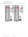
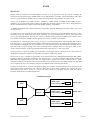
I R T Electronics Pty Ltd A.B.N. 35 000 832 575
26 Hotham Parade, ARTARMON N.S.W. 2064 AUSTRALIA
National: Phone: (02) 9439 3744
Fax: (02) 9439 7439
International:
+61 2 9439 3744
+61 2 9439 7439
Email: [email protected]
Web: www.irtelectronics.com
IRT Eurocard
Types MMM-4230 & MMX-4230
4 Channel ASI to G.703 Multiplexer / De-Multiplexer
Designed and manufactured in Australia
IRT can be found on the Internet at:
http://www.irtelectronics.com
4230-mmm & 4230-mmx.ib.rev4.doc
Page 1 of 17
17/10/2007
IRT Eurocard
Types MMM-4230 & MMX-4230
4 Channel ASI to G.703 Multiplexer/De-Multiplexer
Instruction Book
Table of Contents
Section
Page
Operational Safety
General Description
Technical Specifications
Configuration
Link settings
Switch settings
45 Mb version
Variable Bandwidth – Channel Allocation Selection A
34 Mb version
Installation
SMU-4000 Installation
Figure 1: SMU-4000 module
RS-422 pin assignments
The RS-422 standard
Front and rear layouts
SNMP – What Is It?
Maintenance & Storage
Warranty & Service
Equipment return
Drawing List Index
2
3
4
5
5
6
6
7
8
9
10
10
11
12
13
14
16
16
16
17
This instruction book applies to units later than S/N 0504001.
Operational Safety:
WARNING
Operation of electronic equipment involves the use of voltages and currents that
may be dangerous to human life. Note that under certain conditions dangerous
potentials may exist in some circuits when power controls are in the OFF position.
Maintenance personnel should observe all safety regulations.
Do not make any adjustments inside equipment with power ON unless proper
precautions are observed. All internal adjustments should only be made by suitably
qualified personnel. All operational adjustments are available externally without the
need for removing covers or use of extender cards.
4230-mmm & 4230-mmx.ib.rev4.doc
Page 2 of 17
17/10/2007
IRT Eurocard
Types MMM-4230 & MMX-4230
4 Channel ASI to G.703 Multiplexer/De-Multiplexer
General Description
MMM-4230
MMX-4230
ASI-1
ASI-1
Input
ASI-2
Input
Output
Processing
&
De-Mux
Mux
&
Signal
Processing
ASI-2
Output
G.703
G.703
Output
Input
ASI-3
ASI-3
Input
Output
ASI-4
ASI-4
Input
Output
SNMP
SNMP
DATA
DATA
Input
Output
The MMM-4230 and MMX-4230 are part of a family of data transcoders for converting between the commonly
used MPEG2 Transport Stream formats for video distribution in the broadcast industry.
With the MMM-4230 up to four ASI and one RS422 data signals can be multiplexed together and converted into a
framed or unframed DS3 signal for transmission down a single 45 Mb/s G.703 line.
The MMX-4230 converts and demultiplexes the 45 Mb/s G.703 signal back into the original four ASI signals (at
their original rates) and the RS422 data signal.
An on board switch on the MMM-4230 sets the maximum data rates for each ASI input allowing the efficient use of
the available bandwidth and for protection against overuse of the bandwidth by the other channels. Total maximum
data rate up to 43.5 Mb/s is allowed. Temporary packet stuffing is used to automatically bring the rate up to
45 Mb/s.
Inputs are automatically equalised for lengths of up to 300m of Belden 8281 or equivalent cable.
RS422 9600 Baud uni-directional data may also be sent on the same link.
Front panel indication and relay alarm on the MMM-4230 transmitter shows if there is an input data rate violation.
Corresponding alarm on the MMX-4230 receiver shows a loss of G.703 input.
An optional Simple Network Management Protocol (SNMP) plug-in module is available for remote monitoring of
input and output status, control and alarm states.
The MMM-4230 and MMX-4230 are designed to fit IRT’s standard Eurocard frames as well as IRT’s 4000 series
frame for use with IRT’s SNMP system and may be used alongside any other of IRT’s analogue or digital
Eurocards.
Note: Also available in a 34 Mb/s G.703 version. See “Configuration - switch settings” section for configuration
table.
Standard features:
• Up to 4 ASI and 1 Data stream on one 45 Mb/s G.703 link
• Input rate stuffing to 45 Mb/s G.703 rate
• Selectable input maximum data rates
• Automatic Input equalisation up to 300m
• Suitable for Single Frequency Network (SFN) use
• Optional SNMP plug-in monitoring and control module
• Eurocard format
4230-mmm & 4230-mmx.ib.rev4.doc
Page 3 of 17
17/10/2007
Technical Specifications
MMM-4230:
Inputs:
Type 1
Maximum Data Rate
4 x ASI-C 75Ω, 800 mVp-p, BNC connector.
40.1 Mb/s (for 188 byte packet),
43.5 Mb/s (for 204 byte packet).
Channel Data Rate Assignments
(for 188 byte packet length signals)
I/P1
40
35
30
25
20
30
25
20
20
13.5
20
15
15
10
Type 2
I/P2
I/P3
+ 0 + 0
+ 5 + 0
+ 10 + 0
+ 15 + 0
+ 20 + 0
+ 5 + 5
+ 10 + 5
+ 15 + 5
+ 10 + 10
+ 13.5 +13.5
Variable
+ 10 + 5
+ 15 + 5
+ 10 + 10
+ 10 + 10
+
+
+
+
+
+
+
+
+
+
I/P4 (Mb/s)
0
0
0
0
0
0
0
0
0
0
+ 5
+ 5
+ 5
+ 10
RS422 9600 Baud Uni directional.
Output:
Type
Electrical Characteristics
Data Rate
1 x G.703, 75Ω BNC connector.
B3ZS encoded.
44.736 Mb/s.
Alarm Output:
Contact closure on error, loss of power.
MMX-4230:
Input:
Type
Electrical Characteristics
Data Rate
1 x G.703, 75Ω BNC connector.
B3ZS encoded.
44.736 Mb/s.
Outputs:
Type 1
Data Rate
Type 2
4 x ASI-C 75Ω, 800 mVp-p, BNC connector.
same as MMM-4230 input rate.
RS-422 9600 Baud Uni directional.
Alarm Output:
Contact closure on loss of G.703 input, loss of power.
Power Requirements
28 Vac CT (14-0-14) or ±16 Vdc.
6.5 VA.
Power consumption
Other
Temperature range
Mechanical
Finish
Front panel
Rear assembly
Dimensions
Optional Accessories
NOTE:
0 - 50° C ambient.
Suitable for mounting in IRT 19" rack chassis with input, output and power
connections on the rear panel.
Grey, silk-screened black lettering & red IRT logo.
Detachable silk-screened PCB with direct mount connectors to Eurocard and
external signals.
6 HP x 3 U x 220 mm IRT Eurocard.
SNMP plug-in module for use with 4000 series frame fitted with SNMP
“Agent”.
Also available in a 34 Mb/s G.703 version.
Due to our policy of continuing development, these specifications are subject to change without notice.
4230-mmm & 4230-mmx.ib.rev4.doc
Page 4 of 17
17/10/2007
Configuration
Link settings
MMM-4230 CONFIGURATION INFORMATION
Program 4230mmm.tdf
LK6A Installed
LK1 IN
When using Switch 1 position A ‘Variable Bandwidth’, if the frequency of an input that has an
assignment of 26.8Mb/s falls below 13.4Mb/s then the assignment will revert to 13.4Mb/s. All other
conditions mentioned in the Variable Bandwidth section still apply.
OUT The frequency resetting mentioned above does not occur.
LK2 IN
Existing Reed Solomon encoding on ASI streams will pass through system.
If no RS is present on the input then RS encoding is added.
OUT Reed Solomon encoding added to input ASI steams regardless of whether existing RS encoding exists
or not.
LK3
Not used.
Output G.703 signal will be “framed”.
LK4* IN
OUT Output G.703 signal will be “unframed”.
Output “unshaped” (recommended for output drive lengths > 68m (225ft)).
LK5* IN
OUT Output “shaped” (recommended for output drive lengths < 68m (225ft)).
LK7
Installing this link will terminate the RS-422 data line.
Note: *
Not applicable for 34 Mb/s (E3) version.
MMX-4230 CONFIGURATION INFORMATION
LK1 IN
Allows instantaneous changes in channel bandwidth allocation as required by the “Variable” Data
Assignment.
OUT Error concealment is applied to the packet distribution.
LK2 IN
Output packet size is always 204 byte and will contain Reed Solomon code regardless of
corresponding MMM-4230 input packet size.
OUT Output packet size matches that of corresponding MMM-4230 input packet size.
LK3 IN
Outputs can be individually disabled by SNMP remote control. Note that this requires SNMP
functionality within IRT’s SNMP frame.
OUT All outputs are always enabled. SNMP functionality not required.
For input G.703 signal that is “framed”.
LK4* IN
OUT For input G.703 signal that is not “framed”.
LK5 IN
Input G.703 equaliser not enabled.
OUT Input G.703 equaliser enabled.
LK10
Installing this link will terminate the RS-422 data line.
Note: *
Not applicable for 34 Mb/s (E3) version.
4230-mmm & 4230-mmx.ib.rev4.doc
Page 5 of 17
17/10/2007
Switch settings
MMM-4230 45Mb version:
The MMM-4230 Multiplexer works in a channel protection mode. The necessity for protection arises if the data rate
of the inputs exceeds the maximum allowable for an MMM-4230 Transmitter (43.5Mb/s). Without protection all
used channels would suffer errors. With protection, the available data rate can be divided among the input channels
and if a channel tries to exceed its allocation only that channel is adversely affected.
A switch, SW1, on the MMM-4230 sets the maximum data rates for each ASI input.
SW1
For 204 byte packets the following allocation is possible.
Switch 1 Position
0
1
2
3
4
5
6
7
8
9
A
B
C
D
E
F
I/P 1
43.5
38.26
32.8
27.33
21.86
32.8
27.33
21.86
21.86
14.6
21.86
16.4
16.4
10.93
Channel Data Rate Assignment
I/P 2
I/P 3
5.46
10.93
16.4
21.86
5.46
5.46
10.93
5.46
16.4
5.46
10.93
10.93
14.6
14.6
Variable
10.93
5.46
16.4
5.46
10.93
10.93
10.93
10.93
Remote
I/P 4
5.46
5.46
5.46
10.93
For 188 byte packets the following is true –
Switch 1 Position
0
1
2
3
4
5
6
7
8
9
A
B
C
D
E
F
I/P 1
40.10
35.26
30.22
25.18
20.14
30.22
25.18
20.14
20.14
13.47
20.14
15.11
15.11
10.07
Channel Data Rate Assignment
I/P 2
I/P 3
5.03
10.07
15.11
20.14
5.03
5.03
10.07
5.03
15.11
5.03
10.07
10.07
13.47
13.47
Variable
10.07
5.03
15.11
5.03
10.07
10.07
10.07
10.07
Remote
I/P 4
5.03
5.03
5.03
10.07
Note: For Channel allocation selection by SNMP control the Data Rate switch (SW1) must be set to “F”.
These data rates are only the maximum allowed for the channel. Any lower rate may be used.
4230-mmm & 4230-mmx.ib.rev4.doc
Page 6 of 17
17/10/2007
Variable Bandwidth – Channel Allocation Selection A:
For 188 byte packets the following allocation is possible –
I/P 1
40.2
26.8
26.8
26.8
13.4
13.4
13.4
Channel Data Rate Assignment
I/P 2
I/P 3
13.4
13.4
13.4
13.4
13.4
13.4
I/P 4
13.4
13.4
13.4
13.4
-
40.2
26.8
26.8
26.8
13.4
13.4
13.4
13.4
13.4
-
13.4
-
40.2
26.8
26.8
26.8
13.4
13.4
-
13.4
-
40.2
26.8
26.8
If only one channel is present then the total bandwidth is allocated to that channel.
If two channels are present and one exceeds a rate of 13.4 Mb/s then that channel will be assigned 26.8 Mb/s and
the other 13.4 Mb/s. However, input 1 has priority over inputs 2, 3, & 4, input 2 has priority over inputs 3 & 4, and
input 3 has priority over input 4. So even if, say, channel 2 has an input rate above 13.4 Mb/s and then input 1’s rate
also increases above 13.4 Mb/s, then input 1 will be assigned the bandwidth of 26.8 Mb/s whilst input 2’s will be
relegated to 13.4 Mb/s. Once a channel has been assigned a bandwidth of 26.8Mb/s it will retain the allocation until
either its input signal is removed, or until a channel with higher priority requires 26.8Mb/s allocation, or there are
any three channels connected.
If three channels are present they will each be assigned 13.4 Mb/s.
If four channels are present then channel 4 will not get any bandwidth.
The error concealment in the MMX-4230 will not allow an instantaneous change in channel allocation, so this
should be disabled when using the above option by installing link LK1.
4230-mmm & 4230-mmx.ib.rev4.doc
Page 7 of 17
17/10/2007
MMM-4230 34Mb version:
Maximum payload Data Rate
30.86 Mb/s (for 188 byte packet),
33.5 Mb/s (for 204 byte packet).
Channel Data Rate Assignments
(for 188 byte packet length signals)
I/P1
30
27
23
19
15.4
23
19
15.4
15.4
11.5
19
15.4
11.5
11.5
7.7
I/P2
+ 0
+ 3.8
+ 7.7
+ 11.5
+ 15.4
+ 3.8
+ 7.7
+ 11.5
+ 7.7
+ 11.5
+ 3.8
+ 7.7
+ 11.5
+ 7.7
+ 7.7
I/P3
+ 0
+ 0
+ 0
+ 0
+ 0
+ 3.8
+ 3.8
+ 3.8
+ 7.7
+ 7.7
+ 3.8
+ 3.8
+ 3.8
+ 7.7
+ 7.7
I/P4 (Mb/s)
+ 0
+ 0
+ 0
+ 0
+ 0
+ 0
+ 0
+ 0
+ 0
+ 0
+ 0
+ 3.8
+ 3.8
+ 3.8
+ 7.7
In particular, for 204 byte packets the following allocation is possible.
Switch 1 Position
0
1
2
3
4
5
6
7
8
9
A
B
C
D
E
F
I/P 1
33.5
29.31
25.12
20.93
16.75
25.12
20.93
16.75
16.75
12.56
20.93
16.75
12.56
12.56
8.37
Channel Data Rate Assignment
I/P 2
I/P 3
4.18
8.37
12.56
16.75
4.18
4.18
8.37
4.18
12.56
4.18
8.37
8.37
12.56
8.37
4.18
4.18
8.37
4.18
12.56
4.18
8.37
8.37
8.37
8.37
Remote
I/P 4
4.18
4.18
4.18
8.37
Channel Data Rate Assignment
I/P 2
I/P 3
3.85
7.71
11.57
15.43
3.85
3.85
7.71
3.85
11.57
3.85
7.71
7.71
11.57
7.71
3.85
3.85
7.71
3.85
11.57
3.85
7.71
7.71
7.71
7.71
Remote
I/P 4
3.85
3.85
3.85
7.71
And for 188 byte packets the following is true –
Switch 1 Position
0
1
2
3
4
5
6
7
8
9
A
B
C
D
E
F
I/P 1
30.86
27.00
23.14
19.28
15.43
23.14
19.28
15.43
15.43
11.57
19.28
15.43
11.57
11.57
7.71
Note: For Channel allocation selection by SNMP control the Data Rate switch (SW1) must be set to “F”.
These data rates are only the maximum allowed for the channel. Any lower rate may be used.
4230-mmm & 4230-mmx.ib.rev4.doc
Page 8 of 17
17/10/2007
Installation
Pre-installation:
Handling:
This equipment may contain or be connected to static sensitive devices and proper static free handling precautions
should be observed.
Where individual circuit cards are stored, they should be placed in antistatic bags. Proper antistatic procedures
should be followed when inserting or removing cards from these bags.
Power:
AC mains supply:
Ensure that operating voltage of unit and local supply voltage match and that correct rating
fuse is installed for local supply.
DC supply:
Ensure that the correct polarity is observed and that DC supply voltage is maintained within
the operating range specified.
Earthing:
The earth path is dependent on the type of frame selected. In every case particular care should be taken to ensure
that the frame is connected to earth for safety reasons. See frame manual for details.
Signal earth: For safety reasons a connection is made between signal earth and chassis earth. No attempt should be
made to break this connection.
Installation in frame or chassis:
See details in separate manual for selected frame type.
Signal Connections:
All ASI & G.703 inputs and outputs are by 75Ω BNC connectors.
Alarm output is via a two-pin 0.1” header. Alarm condition is when there is a short between these two pins. This
corresponds to either a loss of power or if there is an input data rate violation on the MMM-4230, or a loss of power
or a loss of G.703 input on the MMX-4230.
RS-422 data input and output connections are made via HE-14 8 pin double row connectors on both the MMM4230 and the MMX-4230.
SNMP:
When used in an IRT FRU400 Frame with a CDM400 SNMP Module fitted, the MMM-4320 and MMX-4320 can
be interrogated by an SNMP Network Management System and certain functions can also be remotely controlled.
For instance, the channel bandwidth assignment can be altered and any the RS errors that have occurred can be
read.
SNMP Traps on alarm states can be optionally sent.
The MIB (management information base) associated with these devices has the following OIDs (Object Identies):
Alarms
Channel Present
Channel Enabled
Channel Measured Data Rate
Channel Rate Alarm Channel
Channel Packet size
Bandwidth Allocation
Framing
FPGA Version
Reset
Trap Enable
RS Errors
4230-mmm & 4230-mmx.ib.rev4.doc
Page 9 of 17
17/10/2007
SMU-4000 Installation
The SMU-4000 plug-in SNMP management controller module can only be fitted to IRT’s 4000 series modules that
are capable of being SNMP upgradeable. To determine whether a module is SNMP upgradeable, a square section
on the main PCB is silk screened and fitted with three multipin sockets – as shown below:
1J1
1J3
1J2
This is where the SMU-4000 plug-in SNMP management controller module is fitted. The three sets of multipins on
the underside of the SMU-4000 line up with the three sets of multipin sockets on the main PCB module. Align all
pins and then gently press the SMU-4000 all the way down into place.
If the SMU-4000 is not already programmed with the correct firmware to match the module that it is being plugged
into, it then needs to be programmed via the pins on the topside of the SMU-4000.
Note that installation will generally be done by IRT Electronics at the time of ordering.
Note also that an SMU-4000 will only be functionally operational when the main module that it is plugged into is
fitted into an IRT 4000 series frame fitted with a CDM-4000 SNMP agent and being interrogated by a suitable
Network Management System.
Figure 1: SMU-4000 module
4230-mmm & 4230-mmx.ib.rev4.doc
Page 10 of 17
17/10/2007
RS-422 pin assignments
MMM-4230
RA
RB
MMX-4230
TA
TB
Connectors viewed from top.
4230-mmm & 4230-mmx.ib.rev4.doc
Page 11 of 17
17/10/2007
The RS-422 Standard
The RS-422 standard introduced in the early 1970s defines a balanced (or differential) data communications
interface using two separate wires for each signal. Due to the high noise immunity of the RS-422 standard, high
data speeds and long distances can be achieved.
The RS-422 specification allows reliable serial data communications for:
• Distances up to 1200 metres
• Data rates of up to 10 Mb/s
Only one line driver is allowed on a line, and up to ten line receivers can be driven by it. Figure 1.1 illustrates RS422.
RS-422
Transmitter
Line Driver
A(+)
Balanced Line with
Differential Voltages
(-5V to +5V)
RS-422
Receiver
Line Receiver
A(+)
Up to 1200 metres
10
B(-)
B(-)
Com
Com
1
2
9
RS-422 Receivers (up to 10 devices)
Figure 1.1: RS-422 Connection
(Ref: IDC Engineers Pocket Guide)
4230-mmm & 4230-mmx.ib.rev4.doc
Page 12 of 17
17/10/2007
Front & rear panel connector diagrams
The following front panel and rear assembly drawings are not to scale and are intended to show connection order
and approximate layout only.
MMM-4230
MMX-4230
URGENT
ALARM
URGENT
ALARM
INPUT 1
OUTPUT 1
INPUT 2
ASI 1
OUTPUT 2
ASI 1
ASI 2
ASI 2
INPUT 3
ASI 3
OUTPUT 3
ASI 3
INPUT 4
ASI 4
DATA
DATA
ALARM
ALARM
DC
OUTPUT 4
ASI 4
DC
G.703 OUT
G.703 IN
RS-422
RS-422
N140
4230-mmm & 4230-mmx.ib.rev4.doc
N140
Page 13 of 17
17/10/2007
SNMP
What Is It?
SNMP stands for Simple Network Management Protocol. It is an application layer protocol for managing IP
(Internet Protocol) based systems. SNMP enables system administrators to manage system performance, and to find
and solve system problems. SNMP runs over UDP (User Datagram Protocol), which in turn runs over IP.
Three types of SNMP exist: SNMP version 1 (SNMPv1), SNMP version 2 (SNMPv2) and SNMP version 3
(SNMPv3). It is not the intention here to discuss the differences between various versions, only to bring attention to
the fact that IRT Electronics modules, fitted with SNMP capability, use SNMPv1.
An SNMP managed network consists of three key components: Network Management Systems (NMS), agents, and
managed devices.
An NMS is the console through which the network administrator performs network management functions, such as
monitoring status (e.g. alarm states) and remote controlling, of a set of managed devices. One or more NMSs must
exist on any managed network. Generally the NMS is a computer running third party SNMP control software. There
are a number of third party SNMP software applications currently available on the market.
An NMS polls, or communicates with, an agent. An agent is a network management software module that resides in
a managed device. An agent has local knowledge of management information and translates that information into a
form compatible with SNMP. The agent, therefore, acts as an interface between the NMS and the managed devices.
The NMS sends a request message, and control commands for the managed devices, to the agent, which in turn
sends a response message, containing information about the managed devices, back to the NMS.
A managed device contains an SNMP agent and resides on a managed network. Managed devices collect and store
management information and make this information available to NMSs using SNMP.
Managed device agent variables are organised in a tree structure known as a Management Information Base (MIB).
Within the MIB are parameters pertaining to the managed device. An Object Identifier (OID) number within the
MIB defines the managed device type. This is a unique number specific to the model of managed device. Other
information relating to the device is also stored, information such as alarm states, controllable settings, etc. The MIB
tree is organised in such a way that there will be no two MIB files with conflicting placements.
Normally an NMS polls an agent for information relating to the MIB in a managed device to be sent back to the
NMS. When certain conditions are met within the MIB, such as major alarm conditions, for example, the agent
automatically sends what is known as a trap to the NMS without any prompting from the NMS. This allows
automatic notification of a predetermined event.
SNMP Block Diagram
NMS
IP
Network
NMS
4230-mmm & 4230-mmx.ib.rev4.doc
SNMP Agent
Protocol Engine
MIB
SNMP Agent
SNMP Agent
Protocol Engine
MIB
SNMP Agent
SNMP Agent
Protocol Engine
MIB
SNMP Agent
Page 14 of 17
17/10/2007
SNMP with IRT Products
IRT Electronics currently employs SNMPv1 with its 4000 series frame. The frame acts as an agent when fitted with
a CDM-4000 module. This module has its own designated slot next to the power supply so as to not affect the
number of modules that the frame will take. Communication between the NMS, the frame and its loaded modules
are via this CDM-4000 module. Note that the NMS software is third party and not supplied by IRT Electronics.
Ethernet connection for SNMP operation is via an RJ45 connector on the rear of the frame, below the mains inlet.
Ethernet rate runs at either 10 baseT or 100 baseT.
Frame parameters, such as Name, Address and Location, are set via an RS232 interface, a D9 connector on the rear
of the frame below the mains inlet. A software terminal emulator, such as Tera Term or HyperTerminal, is used for
setting and reading the parameters of the frame.
IRT modules that are SNMP compatible need a plug-in SMU-4000 module with a program relevant to the module
that it is plugged into. Depending on the module, besides the module identification, parameters such as alarm states,
inputs and controls etc. are communicated to the CDM-4000 agent via a data bus on the rear of the frame. Thus the
CDM-4000 collects information on what is loaded within the frame, what positions they occupy, and their current
status for communication to the NMS when the NMS sends a request for information.
In the event of a major alarm from any of the SNMP compatible modules, or power supplies, a trap is automatically
sent by the CDM-4000 agent to the NMS without any prompting by the NMS. This alerts the operator to any fault
conditions that may exist that need immediate attention.
110/240 V 50/60 Hz
0.7 A (max.)
FRU-4000
FRAME
FUSES
220/240 Vac
500 mA S.B.
110/120 Vac
1A S.B.
RS232
Alarm
Ethernet
+
48Vdc
AS3260 approval no.: CS6346N
Ass. no.: 804692
IRT SNMP Connections
IRT modules fitted
with SMU-4000
NMS
Network
Ethernet Cable
CDM-4000
PSU’s
IRT 4000 Series Frame
Ethernet Cable
IRT modules fitted
with SMU-4000
CDM-4000
PSU’s
IRT 4000 Series Frame
Ethernet Cable
IRT 4000 Series SNMP Setup
4230-mmm & 4230-mmx.ib.rev4.doc
Page 15 of 17
17/10/2007
Maintenance & storage
Maintenance:
No regular maintenance is required.
Care however should be taken to ensure that all connectors are kept clean and free from contamination of any kind.
This is especially important in fibre optic equipment where cleanliness of optical connections is critical to
performance.
Storage:
If the equipment is not to be used for an extended period, it is recommended the whole unit be placed in a sealed
plastic bag to prevent dust contamination. In areas of high humidity a suitably sized bag of silica gel should be
included to deter corrosion.
Where individual circuit cards are stored, they should be placed in antistatic bags. Proper antistatic procedures
should be followed when inserting or removing cards from these bags.
Warranty & service
Equipment is covered by a limited warranty period of three years from date of first delivery unless contrary
conditions apply under a particular contract of supply. For situations when “No Fault Found” for repairs, a
minimum charge of 1 hour’s labour, at IRT’s current labour charge rate, will apply, whether the equipment is within
the warranty period or not.
Equipment warranty is limited to faults attributable to defects in original design or manufacture. Warranty on
components shall be extended by IRT only to the extent obtainable from the component supplier.
Equipment return:
Before arranging service, ensure that the fault is in the unit to be serviced and not in associated equipment. If
possible, confirm this by substitution.
Before returning equipment contact should be made with IRT or your local agent to determine whether the
equipment can be serviced in the field or should be returned for repair.
The equipment should be properly packed for return observing antistatic procedures.
The following information should accompany the unit to be returned:
1.
2.
3.
4.
5.
6.
7.
A fault report should be included indicating the nature of the fault
The operating conditions under which the fault initially occurred.
Any additional information, which may be of assistance in fault location and remedy.
A contact name and telephone and fax numbers.
Details of payment method for items not covered by warranty.
Full return address.
For situations when “No Fault Found” for repairs, a minimum charge of 1 hour’s labour will apply,
whether the equipment is within the warranty period or not. Contact IRT for current hourly rate.
Please note that all freight charges are the responsibility of the customer.
The equipment should be returned to the agent who originally supplied the equipment or, where this is not
possible, to IRT direct as follows.
Equipment Service
IRT Electronics Pty Ltd
26 Hotham Parade
ARTARMON
N.S.W.
2064
AUSTRALIA
Phone:
Email:
4230-mmm & 4230-mmx.ib.rev4.doc
61 2 9439 3744
[email protected]
Page 16 of 17
Fax:
61 2 9439 7439
17/10/2007
Drawing List Index
Drawing #
Sheet #
Description
804900
804900
804900
804902
804902
804902
1
2
3
1
2
3
MMM-4230 4 Channel ASI to G.703 Multiplexer Schematic – sheet 1
MMM-4230 4 Channel ASI to G.703 Multiplexer Schematic – sheet 2
MMM-4230 4 Channel ASI to G.703 Multiplexer Schematic – sheet 3
MMX-4230 G.703 to 4 Channel ASI De-Multiplexer schematic – sheet 1
MMX-4230 G.703 to 4 Channel ASI De-Multiplexer schematic – sheet 2
MMX-4230 G.703 to 4 Channel ASI De-Multiplexer schematic – sheet 3
4230-mmm & 4230-mmx.ib.rev4.doc
Page 17 of 17
17/10/2007
PC 804998
Input-4
Input-3
Input-2
Input-1
R64
75R
R1
75R
L3
0.022uH
R69
47
R15
75R
L2
R14
0.033uH
75R
R67
47
L4
0.022uH
R66
47
L1
0.022uH
C2 1uF
C21
C1
0.1uF
+
C7
C14
C9
0.1uF
C12
0.1uF
R19
100R
1uF
R10
100R
R42
100R
1uF
R2
100R
1uF
C19
0.1uF
+
R33
47
+
+
CD25
0.1uF
C6
0.1uF
CD50
0.1uF
CD46
0.1uF
C5
0.1uF
CD3
0.1uF
C4
100pF
100pF
C10
C11
C15
0.1uF
100pF
+5VB
+5VB
C18
CD31
0.1uF
100pF
+5VB
+5VB
10K
R68
10K
R65
10K
R23
10K
7
6
5
4
3
2
1
7
6
5
4
3
2
1
7
6
5
4
3
2
1
7
6
5
4
3
2
1
AEC-
AEC+
CD
Vcc
EOM
Vcc
Vcc
DO
!DO
DI
!DI
Vee
Vee
DI
!DI
Vee
Vee
!MUTE
DO
!DO
DI
!DI
Vee
Vee
!MUTE
CLC014
U6
AEC-
AEC+
CD
Vcc
EOM
Vcc
Vcc
DO
!DO
DI
!DI
Vee
Vee
!MUTE
CLC014
U4
AEC-
AEC+
CD
Vcc
EOM
Vcc
Vcc
DO
!DO
!MUTE
CLC014
U8
AEC-
AEC+
CD
Vcc
EOM
Vcc
Vcc
CLC014
U2
8
9
10
11
12
13
14
8
9
10
11
12
13
14
8
9
10
11
12
13
14
8
9
10
11
12
13
14
R18
120R
R12
75R
C13
0.1uF
CD21
10uF
+5VB
R17
75R
CD20
10uF
+5VB
C8
0.1uF
R21
75R
D3
BAS32L
R11
120R
R20
75R
CD1
10uF
+5VB
C20
0.1uF
R8
75R
D2
BAS32L
R28
120R
R6
75R
CD11
10uF
+5VB
C3
0.1uF
R22
75R
D4
BAS32L
R3
120R
R5
75R
D1
BAS32L
10K
CD8
CD10
10K
R9
CD53 CD52
10K
R13
CD22
3
2
1
28
27
26
CD23 4
10K
R16
0.1uF 0.1uF 0.1uF
CD27
+5VB
4
3
2
1
28
27
26
0.1uF 0.1uF 0.1uF
CD57
+5VB
4
3
2
1
28
27
26
0.1uF 0.1uF 0.1uF
CD2
+5VB
0.1uF 0.1uF 0.1uF
4
3
2
1
28
27
26
!BISTEN
A/!B
INA+
INA-
INB+
INB-
MODE
!BISTEN
A/!B
INA+
INA-
INB+
INB-
MODE
!BISTEN
A/!B
INA+
INA-
INB+
INB-
MODE
!BISTEN
A/!B
INA+
INA-
INB+
INB-
MODE
25
REFCLK
R7
CD12 CD13 CD14
+5VB
+5VB
U5
CY7B933
+5VB
+5VB
U9
CY7B933
+5VB
+5VB
U3
CY7B933
+5VB
+5VB
+5VB
CY7B933
U7
+5VB
+5VB
+5VB
+5VB
+5VB
+5VB
+5VB
20
GND
R4
24
6
RF
5
25
REFCLK
RF
5
24
6
23
SO
!RDY
!RDY
24
22
CKR
GND
GND
GND
25
REFCLK
RF
5
25
REFCLK
6
24
GND
6
RF
5
Vccq
GND
Vccq
8
22
CKR
7
23
SO
!RDY
7
23
SO
8
22
CKR
GND
Vccq
GND
Vccq
8
22
CKR
7
23
SO
!RDY
7
GND
8
+5VB
19
Qa (SC/!D)
Qh (Q7)
21
Vccq
Vccn
9
21
Vccq
Vccn
9
21
Vccq
Vccn
9
Vccq
9
Vccn
21
Qj (RVS)
10
20
GND
11
19
Qa (SC/!D)
Qh (Q7)
11
Qj (RVS)
10
20
GND
Qj (RVS)
19
Qa (SC/!D)
Qh (Q7)
11
19
Qa (SC/!D)
10
20
GND
Qj (RVS)
10
Qh (Q7)
11
Qg (Q6)
Qf (Q5)
Qi (Q4)
Qe (Q3)
Qd (Q2)
Qc (Q1)
Qb (Q0)
Qg (Q6)
Qf (Q5)
Qi (Q4)
Qe (Q3)
Qd (Q2)
Qc (Q1)
Qb (Q0)
Qg (Q6)
Qf (Q5)
Qi (Q4)
Qe (Q3)
Qd (Q2)
Qc (Q1)
Qb (Q0)
Qg (Q6)
Qf (Q5)
Qi (Q4)
Qe (Q3)
Qd (Q2)
Qc (Q1)
Qb (Q0)
12
13
14
15
16
17
18
12
13
14
15
16
17
18
12
13
14
15
16
17
18
12
13
14
15
16
17
18
CHD_IN[9]
CHD_IN[8]
CHD_IN[7]
CHD_IN[6]
CHD_IN[5]
CHD_IN[4]
CHD_IN[3]
CHD_IN[2]
CHD_IN[1]
CHD_IN[0]
CHD_CKR
CHD_REF_CLK
CHD_PRES
CHC_IN[9]
CHC_IN[8]
CHC_IN[7]
CHC_IN[6]
CHC_IN[5]
CHC_IN[4]
CHC_IN[3]
CHC_IN[2]
CHC_IN[1]
CHC_IN[0]
CHC_CKR
CHC_REF_CLK
CHC_PRES
CHB_IN[9]
CHB_IN[8]
CHB_IN[7]
CHB_IN[6]
CHB_IN[5]
CHB_IN[4]
CHB_IN[3]
CHB_IN[2]
CHB_IN[1]
CHB_IN[0]
CHB_CKR
CHB_REF_CLK
CHB_PRES
CHA_IN[9]
CHA_IN[8]
CHA_IN[7]
CHA_IN[6]
CHA_IN[5]
CHA_IN[4]
CHA_IN[3]
CHA_IN[2]
CHA_IN[1]
CHA_IN[0]
CHA_CKR
CHA_REF_CLK
CHA_PRES
COPYRIGHT
DO NOT COPY NOR
DISCLOSE TO ANY
THIRD PARTY
WITHOUT WRITTEN
CONSENT
DRAWN
ENG.APR.
CHECKED
Revision: 1
Date: 1-Feb-2005
Drawing No.
Title
804900
MMM-4230
Sheet
1 of 3
IRT Electronics Pty. Ltd.
ARTARMON NSW AUSTRALIA 2064
SCALE
N.T.S.
A2
SIZE
804900S3
804900S3.SCH
804900S2
804900S2.SCH
1
LK5 2
1
LK4 2
1
LK3 2
1
LK2 2
1
LK1 2
7
VccIO
C
SW2
R24
10K
1 +VccIO
2
4
8
10K
R52
CHD_PRES
CHD_REFCLK
CHD_CKR
CHD_IN[0]
CHD_IN[1]
CHD_IN[2]
CHD_IN[3]
CHD_IN[4]
CHD_IN[5]
CHD_IN[6]
CHD_IN[7]
CHD_IN[8]
CHD_IN[9]
TPDATA
DS3/E3
TXLEV
ENCODDIS
TCLK
TNDATA
URGENT RELAY
SW1
10K
R53
+VccIO
10K
R54
1
2
3
4
5
6
7
8
9
10
11
12
13
14
15
16
17
18
19
20
21
22
23
24
25
26
27
28
29
30
31
32
33
34
35
36
37
38
39
40
41
42
43
44
45
46
47
48
49
50
51
52
VCCINT
GNDINT
TMS
nTRST
nSTATUS
VCCIO
GNDINT
GNDINT
VCCINT
VCCIO
GNDINT
initdone
GNDINT
VCCINT
VCCIO
GNDINT
RdynBsy
clkusr
TCLK
config_done
nCeo
TDO
VCCIO
GNDINT
1K
GNDINT
EPF1K50QC208-3
U1
VCCIO
VCCINT
VCCIO
VCCIO
lock
GNDINT
VCCINT
nCS
CS
nWS
nRS
R44
R30
1K
VccIO
CHB_CKR
CHB_REF_CLK
CHB_PRES
VCCIO
OUT
GNDINT
14
8
VCCINT
CD48
0.1uF
10K
R55
CHB_IN9
CHB_IN8
CHB_IN7
CHB_IN6
CHB_IN5
CHB_IN4
CHB_IN3
CHB_IN2
CHB_IN1
CHB_IN0
VCCIO
+5VB
7
1
Vcc
OUT
XTAL_OSC
27MHz
GND
n/c
XTAL2
8
14
CD49
0.1uF
4.7uH
LD5
+5VB
R63
22R
VCCIO
GNDINT
MSEL0
MSEL1
VCCINT
nConfig
VCCIO
GNDINT
VCCINT
GNDINT
VCCINT
GNDINT
VCCIO
GNDINT
VCCIO
GNDINT
DATA0
DCLK
nCE
TDI
VCCINT
GNDINT
156
155
154
153
152
151
150
149
148
147
146
145
144
143
142
141
140
139
138
137
136
135
134
133
132
131
130
129
128
127
126
125
124
123
122
121
120
119
118
117
116
115
114
113
112
111
110
109
108
107
106
105
Port
PTB0
PTB1
PTA1
PTA3
PTA4
PTA6
PTA7
PTA5
PTA2
PTA0
CHC_IN[9]
CHC_IN[8]
CHC_IN[7]
CHC_IN[6]
CHC_IN[5]
CHC_IN[4]
CHC_IN[3]
CHC_IN[2]
CHC_IN[1]
CHC_IN[0]
CHC_CHR
CHC_REFCLK
CHA_IN[3]
CHA_IN[2]
CHA_IN[1]
CHA_IN[0]
CHA_CKR
CHA_REFCLK
+VccIO
+VccINT
CHA_IN[8]
CHA_IN[7]
CHA_IN[6]
CHA_IN[5]
CHA_IN[4]
CHA_IN[9]
CHC_PRES
CHA_PRES
CD6,15,16,17,18,19,28,30,36
0.1uF
VccIO
R49
LED5
Vcc
XTAL_OSC
44.7MHz
R38 10K
R56
LED7
560R
LD1
560R
+5V
A
B
VCC
R39
1K
1K
R41
8
5
6
5
R32
1K
+5V
GND
MAX485
DI
DE
RE
RO
U15
+5V
4
3
2
1
VccIO
CD9,33,35
10uF
VccIO
CD34,37
10uF
+VccINT
560R
CD5,7,24,26,29,32,47,54,55
0.1uF
2
nReset
+5V
CD42
470uF
VccIO
CD43
470uF
+VccINT
LK6
LK7
LK
560R
+VccINT
560R
GND
R37 10K
R48
LED4
n/c
R36 10K
R47
LED3
1
R35 10K
R46
LED2
XTAL1
R34 10K
dev_oe
VCCINT
input
clock
input
GNDINT
dev_clrn
GNDINT
VCCCLK
input
clock
input
GNDCLK
GNDINT
R45
LED1
4.7uH
VCCIO
208
207
206
205
204
203
202
201
200
199
198
197
196
195
194
193
192
191
190
189
188
187
186
185
184
183
182
181
180
179
178
177
176
175
174
173
172
171
170
169
168
167
166
165
164
163
162
161
160
159
158
157
53
54
55
56
57
58
59
60
61
62
63
64
65
66
67
68
69
70
71
72
73
74
75
76
77
78
79
80
81
82
83
84
85
86
87
88
89
90
91
92
93
94
95
96
97
98
99
100
101
102
103
104
560R
3
1
R50
220R
1
2
3
4
1
2
3
4
2
4
6
8
10
DATA VCC
DCLK VCC
OE nCASC
nCS
GND
U13
EPC1
DATA VCC
DCLK VCC
OE nCASC
nCS
GND
U14
EPC1
HEADER 5X2
1
3
5
7
9
J4
+5V
8
7
6
5
8
7
6
5
+5V
COPYRIGHT
DO NOT COPY NOR
DISCLOSE TO ANY
THIRD PARTY
WITHOUT WRITTEN
CONSENT
DRAWN
ENG.APR.
CHECKED
Revision: 1
Date: 1-Feb-2005
1K
R29
1K
R31
RS422-RA
RS-422RB
Drawing No.
Title
Vbatt
!RESET
!MR
!PFO
U12
MAX704
Vout
VCC
GND
PFI
R40
10K
804900
MMM-4230
8
7
6
5
Sheet
2 of 3
IRT Electronics Pty. Ltd.
ARTARMON NSW AUSTRALIA 2064
SCALE
N.T.S.
A2
SIZE
10uF
CD39
1
2
3
4
+5V
TXLEV
ENCODIS
DS3/E3
TCLK
TNDATA
TCLK
TNDATA
TXLEV
ENCODIS
DS3/E3
GND
+5B
26
25
2
3
19
20
4
12
27
28
1
7
8
9
5
11
ICT
TXLEV
RLOOP
LLOOP
MRING
MTIP
DS3/E3
U10
GND
GNDA
VDDA
VDD
VCCIO
VCCINT
TRING
TTIP
BPV
RNRZ
RNEG
RPOS
RCLKO
DMO
XR-T7296
DECODIS
RPDATA
RNDATA
RCLK
TPDATA
TNDATA
TCLK
TAOS
ENCODIS
22
23
13
14
15
16
17
18
10
21
24
6
TP7
3.3V
TP5
2.5V
2
VCCIO
VCCINT
+5B
33R
R58
33R
R57
+5B
GND
R61
220R
U17
REG_LM3940
220R
R62
1
2
1
GND
100n
CD45
U16
LM317S
D5
BAV99
3
D6
BAV99
CD44
100n
+5B
3
4
TPDATA
1
INPUT
470u
CB4
6
T1
113B7
5
LD2
G703OUT
+5V
8
5
-V
470u
CB5
+5VB
PBBA-D
V+ +V
V-
CONV1
1
4
330u
CB7
PTA7
PTA6
PTA5
PTA4
PTA2
PTA3
PTA0
PTA1
330u
CB6
330u
CB3
URGENT RELAY
IND
22uH
22uH
LD4
1
8
3
POWER
Q1
BSS123
RL1
COIL
PTB1
PTB0
PTB3
PTB2
PTB5
PTB4
PTB7
PTB6
GND
GND
GND
+5V
RX
TX
nRESET
3
DB2
DB106
3
DB1
DB106
+5VB
SNMP
M1
LED6
R51
820R
+5V
330u
CB1
R43
4K7
PTA7
PTA6
PTA5
PTA4
PTA2
PTA3
PTA0
PTA1
GND
GND
330u
CB2
A1
A2
A3
A4
A5
A6
A7
A8
A9
A10
3
2
TPDATA
ADJUST
1
INPUT
3
OUTPUT
2
COMMON
2
OUTPUT
3
6
4
6
4
B1
B2
B3
B4
B5
B6
B7
B8
B9
B10
S1
S2
S3
S4
S5
S6
1
1
+5V
PTB1
PTB0
1
RL1
CONTACT
nReset
5
EMI4
FILTER
EMI3
FILTER
EMI2
FILTER
EMI1
FILTER
1R
F4
1R
1R
F3
F2
1R
F1
G703OUT
Input-4
RS422-RA
RS422-RB
Input 3
Input-2
Input-1
M1
M2
M2
M1
1A
1B
2A
2B
3A
3B
4A
4B
5A
5B
6A
6B
7A
7B
8A
8B
9A
9B
10A
10B
11A
11B
12A
12B
13A
13B
14A
14B
15A
15B
16A
16B
17A
17B
18A
18B
19A
19B
20A
20B
21A
21B
22A
22B
23A
23B
24A
24B
25A
25B
26A
26B
27A
27B
28A
28B
29A
29B
30A
30B
31A
31B
32A
32B
J1
DIN64F
A2
SIZE
G703
OUTPUT
J5
4B
P2
1A
804900
MMM-4230
RS-422
Sheet
3 of 3
IRT Electronics Pty. Ltd.
ARTARMON NSW AUSTRALIA 2064
Drawing No.
1
2
URGENT ALARM
Title
J3
AC
MTMM-PWR
P3
SK4
INPUT 3
ASI
SK3
INPUT 3
ASI
SK2
INPUT 2
ASI
SK1
INPUT 1
ASI
SK5
BNC
1
2
3
1
2
3
4
5
6
5
4
MTMM-103
P1
SCALE
N.T.S.
0.022uH
L9
0R
R73
0R
R72
0R
R71
0R
R70
COPYRIGHT
DO NOT COPY NOR
DISCLOSE TO ANY
THIRD PARTY
WITHOUT WRITTEN
CONSENT
DRAWN
ENG.APR.
CHECKED
Revision: 1
Date: 1-Feb-2005
1A
1B
2A
2B
3A
3B
4A
4B
5A
5B
6A
6B
7A
7B
8A
8B
9A
9B
10A
10B
11A
11B
12A
12B
13A
13B
14A
14B
15A
15B
16A
16B
17A
17B
18A
18B
19A
19B
20A
20B
21A
21B
22A
22B
23A
23B
24A
24B
25A
25B
26A
26B
27A
27B
28A
28B
29A
29B
30A
30B
31A
31B
32A
32B
P1
DIN64M
1
2
3
PC804996
CHD_ENA
CHD_CKW
CHD_SC/D
CHD_D0
CHD_D1
CHD_D2
CHD_D3
CHD_D4
CHD_D5
CHD_D6
CHD_D7
CHD_SVS
CHC_ENA
CHC_CKW
CHC_SC/D
CHC_D0
CHC_D1
CHC_D2
CHC_D3
CHC_D4
CHC_D5
CHC_D6
CHC_D7
CHC_SVS
CHB_ENA
CHB_CKW
CHB_SC/D
CHB_D0
CHB_D1
CHB_D2
CHB_D3
CHB_D4
CHB_D5
CHB_D6
CHB_D7
CHB_SVS
CHA_ENA
CHA_CKW
CHA_SC/D
CHA_D0
CHA_D1
CHA_D2
CHA_D3
CHA_D4
CHA_D5
CHA_D6
CHA_D7
R1
22R
R13
22R
R12
22R
18
17
16
15
14
13
12
18
17
16
15
14
13
12
18
17
16
15
14
13
12
18
17
16
15
14
13
12
D0 (Db)
D1 (Dc)
D2 (Dd)
D3 (De)
D4 (Di)
D5 (Df)
D6 (Dg)
D0 (Db)
D1 (Dc)
D2 (Dd)
D3 (De)
D4 (Di)
D5 (Df)
D6 (Dg)
D0 (Db)
D1 (Dc)
D2 (Dd)
D3 (De)
D4 (Di)
D5 (Df)
D6 (Dg)
D0 (Db)
D1 (Dc)
D2 (Dd)
D3 (De)
D4 (Di)
D5 (Df)
D6 (Dg)
19
11
19
11
19
11
D7 (Dh)
CHA_SVS
11
D7 (Dh)
SC/!D (Da)
19
10
SVS (Dj)
GND
20
SC/!D (Da)
D7 (Dh)
10
SVS (Dj)
GND
20
10
SVS (Dj)
SC/!D (Da)
D7 (Dh)
SC/!D (Da)
8
U2
CY7B923
!RP
9
9
GND
20
20
SVS (Dj)
21
GND
10
Vccq
CKW
21
7
23
Vccq
22
8
U8
CY7B923
!RP
9
Vccq
CKW
21
7
23
Vccq
22
8
U5
CY7B923
!RP
Vccq
22
9
Vccq
7
23
U6
CY7B923
CKW
21
Vccq
7
MODE
8
!RP
Vccq
22
ENA
23
CKW
MODE
5
BISTEN
6
GND
ENN
24
FOTO
25
ENA
MODE
5
BISTEN
6
GND
ENN
24
FOTO
25
5
BISTEN
ENA
MODE
ENA
6
GND
ENN
24
FOTO
25
5
BISTEN
6
GND
ENN
24
FOTO
25
Vccn
OutA-
OutA+
OutB+
OutB-
OutC-
OutC+
Vccn
OutA-
OutA+
OutB+
OutB-
OutC-
OutC+
Vccn
OutA-
OutA+
OutB+
OutB-
OutC-
OutC+
Vccn
OutA-
OutA+
OutB+
OutB-
OutC-
OutC+
26
27
28
1
2
3
4
26
27
28
1
2
3
4
26
27
28
1
2
3
4
26
27
28
1
2
3
4
+5Vb
CD21
0.1uF
+5Vb
CD10
0.1uF
+5Vb
CD53
0.1uF
+5Vb
CD2
0.1uF
R17
75R
R18
75R
+5Vb
R8
75R
R7
75R
+5Vb
R21
75R
R20
75R
+5Vb
R5
75R
R2
75R
+5Vb
R15
100R
R16
100R
CD22
0.1uF
R10
100R
R9
100R
CD11
0.1uF
R23
100R
R22
100R
CD54
0.1uF
R6
100R
R4
100R
CD1
0.1uF
+5Vb
+5Vb
+5Vb
+5Vb
8
7
6
5
8
7
6
5
8
7
6
5
8
7
6
5
Vcc
IN+
IN-
Vee
U7
Q0
!Q0
Q1
!Q1
Q0
!Q0
Q1
!Q1
Q0
!Q0
Q1
!Q1
Q0
!Q0
Q1
!Q1
CLC007
U4
CLC007
U9
CLC007
CLC007
Vcc
IN+
IN-
Vee
Vcc
IN+
IN-
Vee
Vcc
IN+
IN-
Vee
U3
1
2
3
4
4
1
2
3
4
1
2
3
4
1
2
3
CD20
0.1uF
+5Vb
R11
75R
+5Vb
R24
75R
+5Vb
R3
75R
R14
75R
CD12
0.1uF
CD52
0.1uF
CD8
0.1uF
+5Vb
C3
0.1uF
CD14
10uF
C2
0.1uF
CD13
10uF
C6
0.1uF
CD42
10uF
C1
0.1uF
CD3
10uF
Output-4
Output-3
Output-2
Output-1
+5Vb
+5Vb
OUT
Vcc
XTAL2
10uH
OUT
Vcc
27MHz OSC
GND
Vctrl
LD6
44MHz OSC
GND
Vctrl
COPYRIGHT
DO NOT COPY NOR
DISCLOSE TO ANY
THIRD PARTY
WITHOUT WRITTEN
CONSENT
DRAWN
ENG.APR.
CHECKED
Revision: 1
Date: 1-Feb-2005
7
1
7
1
XTAL1
LD5 10uH
8
14
8
A2
SIZE
XTAL_27M
CD50
0.1uF
804902
MMX-4230
Sheet
1 of 3
IRT Electronics Pty. Ltd.
ARTARMON NSW AUSTRALIA 2064
Drawing No.
Title
XTAL_44M
SCALE
N.T.S.
14
CD51
0.1uF
804902S3
804902S3.SCH
804902s2
804902s2.sch
1
LK5 2
1
LK4 2
1
LK3 2
1
LK2 2
10K
10K
VccIO
R36
1
10K
10K
R37
R38
10K
CHD_ENA
CHD_CKW
CHD_SC/D
CHD_D0
CHD_D1
CHD_D2
CHD_D3
CHD_D4
CHD_D5
CHD_D6
CHD_D7
CHD_SVS
RLos
EQ
RNdata
RPdata
Rclk
RefClk
URGENT RELAY
1
2
3
4
5
6
7
8
9
10
11
12
13
14
15
16
17
18
19
20
21
22
23
24
25
26
27
28
29
30
31
32
33
34
35
36
37
38
39
40
41
42
43
44
45
46
47
48
49
50
51
52
VCCINT
GNDINT
TMS
nTRST
nSTATUS
VCCIO
GNDINT
GNDINT
VCCINT
VCCIO
GNDINT
initdone
GNDINT
VCCINT
VCCIO
GNDINT
RdynBsy
clkusr
TCLK
config_done
nCeo
TDO
VCCIO
GNDINT
EPF1K50QC208-3
U1
GNDINT
dev_oe
VCCINT
input
clock
input
GNDINT
dev_clrn
GNDINT
VCCCLK
input
clock
input
GNDCLK
GNDINT
VCCIO
VCCINT
GNDINT
VCCIO
VCCIO
lock
GNDINT
VCCINT
nCS
CS
nWS
nRS
1K
VCCIO
R44
VccIO
VCCIO
LK1 2
R35
R30
1K
VCCINT
XTAL_44M
VCCIO
208
207
206
205
204
203
202
201
200
199
198
197
196
195
194
193
192
191
190
189
188
187
186
185
184
183
182
181
180
179
178
177
176
175
174
173
172
171
170
169
168
167
166
165
164
163
162
161
160
159
158
157
XTAL_27M
53
54
55
56
57
58
59
60
61
62
63
64
65
66
67
68
69
70
71
72
73
74
75
76
77
78
79
80
81
82
83
84
85
86
87
88
89
90
91
92
93
94
95
96
97
98
99
100
101
102
103
104
R34
CHB_SVS
CHB_D7
CHB_D6
CHB_D5
CHB_D4
CHB_D3
CHB_D2
CHB_D1
CHB_D0
CHB_SC/D
CHB_CKW
CHB_ENA
VCCIO
GNDINT
MSEL0
MSEL1
VCCINT
nConfig
VCCIO
GNDINT
VCCINT
GNDINT
VCCINT
GNDINT
VCCIO
GNDINT
VCCIO
GNDINT
DATA0
DCLK
nCE
TDI
VCCINT
GNDINT
156
155
154
153
152
151
150
149
148
147
146
145
144
143
142
141
140
139
138
137
136
135
134
133
132
131
130
129
128
127
126
125
124
123
122
121
120
119
118
117
116
115
114
113
112
111
110
109
108
107
106
105
Port
PTB0
PTB1
PTA1
PTA3
PTA4
PTA6
PTA7
PTA5
PTA2
PTA0
+VccINT
CHC_SVS
CHC_D7
CHC_D6
CHC_D5
CHC_D4
CHC_D3
CHC_D2
CHC_D1
CHC_D0
CHC_SC/D
CHC_CKW
CHC_ENA
CHA_D2
CHA_D1
CHA_D0
CHA_SC/D
CHA_CKW
CHA_ENA
+VccIO
+VccINT
CHA_D7
CHA_D6
CHA_D5
CHA_D4
CHA_D3
CHA_SVS
LED7
LED3
LED2
LED1
LED4
LED5
R29
1K
+5V
nReset
DI
+5V
GND
A
B
VCC
U15
R53
1K
1K
R26
8
5
6
5
R32
1K
+5V
MAX485
DE
RE
RO
+5V
4
3
2
1
2
LK6
R50
220R
+5V 0.1uF
CD48
0.1uF 0.1uF 0.1uF 0.1uF 0.1uF 0.1uF 10uF 10uF 10uF
0.1uF
CD24 CD26 CD29 CD44 CD32 CD34 CD37
CD16 CD7
CD5
3
1
LK10
LK
CD49
0.1uF
VccIO
CD15 CD18 CD19 CD28 CD30 CD36 CD9
CD33 CD35
1
2
3
4
1
2
3
4
2
4
6
8
10
DATA VCC
DCLK VCC
OE nCASC
nCS
GND
U14
EPC1
DATA VCC
DCLK VCC
OE nCASC
nCS
GND
U13
EPC1
HEADER 5X2
1
3
5
7
9
J4
8
7
6
5
8
7
6
5
+5V
COPYRIGHT
DO NOT COPY NOR
DISCLOSE TO ANY
THIRD PARTY
WITHOUT WRITTEN
CONSENT
DRAWN
ENG.APR.
CHECKED
Revision: 1
Date: 1-Feb-2005
10K
R31
RS422-TA
RS422-TB
Drawing No.
Title
Vbatt
!RESET
!MR
!PFO
U12
MAX704
Vout
VCC
GND
PFI
8
7
6
5
+5V
R40
10K
804902
MMX-4230
0.1uF
CD17
Sheet
2 of 3
IRT Electronics Pty. Ltd.
ARTARMON NSW AUSTRALIA 2064
SCALE
N.T.S.
A2
SIZE
10uF
CD39
1
2
3
4
0.1uF 0.1uF 0.1uF 0.1uF 0.1uF 0.1uF 0.1uF 10uF 10uF 10uF
CD6
LED7
DATA
R52
270R
VCCIO
R LOS
LED7
LED5
LED5
LED3mmRED
LED4
LED4
LED3mmGreen
R49
270R
VCCIO
LED3
Channel 4 Present
R48
270R
VCCIO
LED3
LED3mmGreen
Channel 3 Present
LED2
LED2
LED3mmGreen
R47
270R
VCCIO
LED1
Channel 2 Present
R46
270R
VCCIO
LED1
LED3mmGreen
Channel 1 Present
R45
270R
VCCIO
G703in
5
6
4
3
1
2
R27
75
18
5
4
2
EQ
T7295
U10
VCCIO
VCCINT
LPF1
LPF2
Rin
470u
TP7
3.3V
3
6
1
9
10
7
14
15
16
VCCINT
VCCIO
CB6
TP5
2.5V
TMC1
TMC2
GND
GND
GND
RLos
Rclk
RPData
RNData
+5VB
R
R55
U16
LM317S
EQ
RefClk
Rlos
RClk
RPData
RNData
U17
REG_LM3940
R54
R
Issue 1. C4 changed to 100nF from 100pF
100nF
C4
C
C8
+5VB
11
12
+5D
+5C
19
20
LOS
+5A
EXClk
13
T1
113B7
1
INPUT
470u
CB5
LD2
+5V
8
5
-V
470u
CB4
+5VB
PBBA-D
V+ +V
V-
CONV1
1
4
330u
CB8
330u
CB7
PTA7
PTA6
PTA5
PTA4
PTA2
PTA3
PTA0
PTA1
330u
CB3
330u
CB2
URGENT RELAY
R43
4K7
IND
LD3
PWR
LED6
R51
820R
+5V
330u
1
LD4
IND
PTA7
PTA6
PTA5
PTA4
PTA2
PTA3
PTA0
PTA1
GND
GND
CB1
A1
A2
A3
A4
A5
A6
A7
A8
A9
A10
M1
3
DB2
DB106
3
PTB1
PTB0
PTB3
PTB2
PTB5
PTB4
PTB7
PTB6
GND
GND
GND
+5V
RX
TX
nRESET
Q1
BSS123
RL1
COIL
DB1
DB106
8
3
+5V
SNMP
3
2
REPLACE U12 WITH T7295 1EIW
ADJUST
1
INPUT
3
OUTPUT
2
COMMON
2
OUTPUT
3
6
4
6
4
FOR 34.368Mb/s E3
1
1
B1
B2
B3
B4
B5
B6
B7
B8
B9
B10
S1
S2
S3
S4
S5
S6
5
1
RL1
CONTACT
PTB1
PTB0
VCC
nReset
EMI4
FILTER
EMI3
FILTER
EMI2
FILTER
EMI1
FILTER
1R
F4
1R
1R
F3
F2
1R
F1
G7039in
Output4
RS422-TB
RS422-TA
Output3
Output2
Output1
1 28-09-2004 ECR1707
M2
M1
M1
M2
0.015uH
A2
SIZE
6
5
4
J5
804902
MMX-4230
1A
Sheet
3 of 3
IRT Electronics Pty. Ltd.
ARTARMON NSW AUSTRALIA 2064
Drawing No.
4B
RS-422
P2
URGENT ALARM
1
2
MTMM-103
P1
Title
J3
AC
MTMM-PWR
P3
INPUT
SK5
BNC
1
2
3
1
2
3
4
5
SCALE
N.T.S.
0.022uH
L9
L8
0.015uH
SK4
ASI
OUTPUT 4
SK3
ASI
OUTPUT 3
L7
SK2
ASI
OUTPUT 2
ASI
OUTPUT 1
SK1
0.015uH
L6
0.015uH
L5
COPYRIGHT
DO NOT COPY NOR
DISCLOSE TO ANY
THIRD PARTY
WITHOUT WRITTEN
CONSENT
DRAWN
ENG.APR.
CHECKED
Revision: 1
Date: 1-Feb-2005
1A
1B
2A
2B
3A
3B
4A
4B
5A
5B
6A
6B
7A
7B
8A
8B
9A
9B
10A
10B
11A
11B
12A
12B
13A
13B
14A
14B
15A
15B
16A
16B
17A
17B
18A
18B
19A
19B
20A
20B
21A
21B
22A
22B
23A
23B
24A
24B
25A
25B
26A
26B
27A
27B
28A
28B
29A
29B
30A
30B
31A
31B
32A
32B
J1
DIN64F
1A
1B
2A
2B
3A
3B
4A
4B
5A
5B
6A
6B
7A
7B
8A
8B
9A
9B
10A
10B
11A
11B
12A
12B
13A
13B
14A
14B
15A
15B
16A
16B
17A
17B
18A
18B
19A
19B
20A
20B
21A
21B
22A
22B
23A
23B
24A
24B
25A
25B
26A
26B
27A
27B
28A
28B
29A
29B
30A
30B
31A
31B
32A
32B
P1
DIN64M
1
2
3