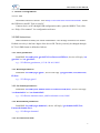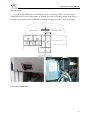
1
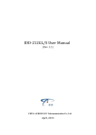
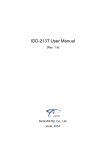
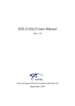
IDD-212GL/S User Manual (Rev. 1.2) China Aerospace Telecommunications Limited May, 2013 IDD-212GL/S User Manual Contents 1. Introduction................................................................................................................................... 3 2. Specifications ............................................................................................................................... 4 2.1 External Interface.................................................................................................................................. 4 2.2 Status Indicator ..................................................................................................................................... 5 2.3 Technical Parameters ............................................................................................................................ 5 3. Device Configuration .................................................................................................................... 7 3.1 PC Tool................................................................................................................................................. 7 3.2 SMS Instructions .................................................................................................................................. 7 4. Installation Instruction................................................................................................................... 9 4.1 SIM Card Installation............................................................................................................................ 9 4.2 OBD Port ............................................................................................................................................ 10 4.3 Device Installation .............................................................................................................................. 10 5. Functions .................................................................................................................................... 12 5.1 OBD Protocols.................................................................................................................................... 12 5.2 Location Inquiry ................................................................................................................................. 12 5.3 Regular GPS Data Reporting .............................................................................................................. 12 5.4 Regular G-Sensor Data Reporting ...................................................................................................... 12 5.5 Regular Diagnostic Data Reporting .................................................................................................... 12 5.6 DTCs Reporting.................................................................................................................................. 12 5.7 Cell ID Reporting ............................................................................................................................... 12 5.8 Trip Mileage ....................................................................................................................................... 13 5.9 Trip Fuel Consumption ....................................................................................................................... 13 5.10 Alarms and Events Reporting ........................................................................................................... 13 5.11 Driver Identification ......................................................................................................................... 13 5.12 Working Mode.................................................................................................................................. 13 5.13 SMS Alert ......................................................................................................................................... 13 5.14 Google Map Link.............................................................................................................................. 14 5.15 Remote Configuration....................................................................................................................... 14 5.16 SMS Configuration ........................................................................................................................... 14 5.17 PC Tool Configuration...................................................................................................................... 14 6. FAQ ............................................................................................................................................ 15 7. Disclaimer................................................................................................................................... 17 1 IDD-212GL/S User Manual 8. Warranty ..................................................................................................................................... 18 9. Statement ................................................................................................................................... 19 2 IDD-212GL/S User Manual 1. Introduction IDD-212GL/S is an intelligent on-board diagnostic device with OBD II and SAE J1939/J1708 (Heavy duty) compliant, it features plug-and-play technology, could read diagnostic info from vehicle ECU and capture location data with optional external GPS, then send them to backend server for real-time remote diagnostic and tracking purpose. Packing List Parts name Quantity Note IDD-212GL/S OBD Dongle 1 ● User Manual 1 ● USB Configuration Cable 1 ○ G-Mouse (HT-166U) 1 ○ Driving Behavior Monitor (HT-196) 1 ○ OBD II extension cable 1 ○ OBD-16 wiring harness 1 ○ 9-Pin deutsch wiring harness 1 ○ 6-Pin deutsch wiring harness 1 ○ Note: (Optional accessories will not be included if there is no indication in the order) 3 IDD-212GL/S User Manual 2. Specifications 2.1 External Interface Product appearance as follows: Standard OBD Connector Connect to the 16 pin on-board Diagnostic Link Connector (DLC). G-Mouse Interface This is a multifunctional interface which is used for device configuration, connecting the G-Mouse or Driving Behavior Monitor. SIM Card slot Insert SIM card. 4 IDD-212GL/S User Manual 2.2 Status Indicator Indicator Color Status Solid on - Power on Power Red Fast blinking - Charging or no internal battery Slow blinking - Working with internal battery Solid off - In sleep LED Slow blinking (on:64ms, off:2s) - Registered network Fast blinking (on:64ms, off:800ms) - No SIM card or GSM LED Orange Network searching Solid off - GSM off Solid on - GSM abnormal Blinking - Trying to access OBD system OBD LED Green Solid on - Successful OBD communication Solid off - No OBD communication G-Mouse Blinking - GPS signal is good Green LED Solid on - Searching for GPS signal Solid off - GPS off One beep - Power on Two beeps - Successful OBD communication Three beeps - Successful log in Buzzer Four beeps - Trip end and stop OBD communication Five beeps - Power off Six beeps - Fail to access OBD system Five beeps (short beep) - Alarm indication 2.3 Technical Parameters Mechanical Interface Dimension 63mm (L) x 50mm (W) x 28mm (H) Weight 50g OBD interface 5 IDD-212GL/S User Manual G-Mouse interface Storage 2MB FLASH, can store up to 24000 GPS data Data Transmission GPRS/SMS Positioning Mode GPS/A-GPS Working Voltage Power 9-36VDC Average Currency: <[email protected] Working Currency Max. Currency: <[email protected] Sleep Currency: <10mA@12VDC Internal Battery 3-axis Accelerometer 3.7V/120mA Lithium battery +/-2g、+/-4g、+/-8g、+/-16g Channels: 50 Sensitivity: -160dBm GPS Accuracy: 5m CEP Cold start: <32s Hot start: <1s Frequency: Quad-band 850/900/1800/1900MHz Protocol: TCP/IP Sensitivity: -107dBm@850/900MHz GSM -106dBm@1800/1900MHz Output Power: Class 4 (2W)@850/900MHz Class 1 (1W)@1800/1900MHz LED Indicator Power/OBD/GSM/GPS Buzzer System status/Alarm indication Antenna Environme nt GSM Antenna Built-in GPS Antenna External Working Temperature Storage Temperature -30℃ ~ +70℃ Humidity 5%〜95%(no frog) -40℃ ~ +85℃ 6 IDD-212GL/S User Manual 3. Device Configuration 3.1 PC Tool Download USB driver and PC Tool at http://www.sinocastel.com/en/Downloads/. Install the USB driver and PC Tool on your PC. Connect device to PC through USB configuration cable, open the OBD PC Tool, click on “Help->User manual” for configuration reference. 3.2 SMS Instructions SMS command is mainly for remote maintenance. The message content is text format. Default secret key is the last 6 digits of the device ID. The key can only be changed through PC Tool. SMS format is defined as follows: 3.2.1 Set IP parameters: Send SMS *SecretKey#set gprs#APN,User,Password,IP,Port*, device will reply *set gprs#ok* or *set gprs#fail*. e.g.: *123456#set gprs#cmnet,,,113.98.241.66,11088* 3.2.2 Read IP parameters: Send SMS *SecretKey#get gprs#*, device will reply *get gprs#APN,User,Password, IP,Port*. e.g.: *123456#get gprs#* 3.2.3 Set domain parameters: Send SMS *SecretKey#set domain #APN,User,Password,IP,Port*, device will reply *set domain#ok* or *set domain#fail*. e.g.: *123456#set domain# cmnet,,,obd.livetelematics.com,11088* 3.2.4 Read domain parameters: Send SMS *SecretKey#get domain#*, device will reply *get domain#APN,User, Password,domain,Port*. e.g.: *123456#get domain#* 3.2.5 Get current location: 7 IDD-212GL/S User Manual Send SMS *SecretKey#position#*, device will reply *position#http://maps.google.com /?q=latitude,longitude*. e.g.: *123456#position#* *123456#position#*http://maps.google.com/?q=22.536934,114.021425* 8 IDD-212GL/S User Manual 4. Installation Instruction 4.1 SIM Card Installation Remove the SIM card cover, insert the SIM card into the device and press gently, then insert the SIM card cover back. 4.1.1 Remove the SIM card cover 4.1.2 Insert the SIM card into the device 4.1.3 Insert the SIM cover 9 IDD-212GL/S User Manual 4.2 OBD Port In general, the OBD port is located in the driver or passenger cabin, from the edge of dashboard on driver side to the border of 300mm. It is easy to touch by sitting in the driver's seat; the preferred location is within the area from steering post to the vehicle centerline. 4.3 Device Installation 10 IDD-212GL/S User Manual Before installing the device, please make sure device has been configured with necessary parameters including network parameters and working mode. Park the car and make sure engine is off, connect the G-Mouse or Driving Behavior Monitor to the device. Fix the G-Mouse or Driving Behavior Monitor above the dashboard horizontally, make sure no mental shielding above them. Plug the device into OBD port, most heavy duties may need 9-Pin or 6-Pin deutsch wiring harness. Start engine, with successful OBD communication the OBD light changes its status to solid on and comes 2 beeps. Then device begins to connect the server, with successful login there comes 3 beeps. If OBD light keeps blinking and comes 6 beeps it means that device is not compatible with the vehicle, please change working mode (see section 5.9 or PC Tool user manual) and try again. Log into www.livetelematics.com to check real-time monitor and trip reports. 11 IDD-212GL/S User Manual 5. Functions 5.1 OBD Protocols Device supports all legislated OBD II protocols; it is also SAE J1939 and SAE J1708 compliant. SAE J1850-PWM SAE J1850-VPW ISO 9141-2 ISO 14230-4 (KWP2000) ISO 15765-4 (CAN) SAE J1939 (Heavy duty) SAE J1587/J1708 (Heavy duty) 5.2 Location Inquiry Upon receiving location inquiry command from server or via SMS, device reports GPS data immediately. 5.3 Regular GPS Data Reporting Device reports GPS data according to configured interval time. 5.4 Regular G-Sensor Data Reporting Device reports G-Sensor data according to configured interval time. 5.5 Regular Diagnostic Data Reporting Device is able to read variety of vehicle diagnostic data, including vehicle speed, engine RPM, engine coolant temperature, mass flow air, etc, and reports up to 10 types of diagnostic data according to configured interval time. 5.6 DTCs Reporting Device is able to read vehicle pending and stored DTCs, and freeze frame data. The backend server analyzes and displays the DTCs for users on time to avoid high repairing cost. 5.7 Cell ID Reporting Device reports Cell ID every 30 seconds when it loses GPS signal. 12 IDD-212GL/S User Manual 5.8 Trip Mileage Device reports driving mileage in each reported message. 5.9 Trip Fuel Consumption Device reports fuel consumption in each reported message. 5.10 Alarms and Events Reporting High RPM High Speed Low Battery Voltage High Engine Coolant Temperature Hard Acceleration Hard Brake Sharp Turn (with optional Driving Behavior Monitor) Sharp Lane Changing (with optional Driving Behavior Monitor) Crash (with optional Driving Behavior Monitor) Excessive Engine Idle Time Fatigue Driving Towed Excessive Exhaust Emission Power On Power Off 5.11 Driver Identification With optional Driving Behavior Monitor the device is able to detect RFID cards and reports card IDs to the server. 5.12 Working Mode Device supports 3 types of working mode: Passenger car, Heavy duty and Tracker mode. In tracker mode, device does not support diagnostic function, trip fuel consumption and some alarms reporting including high RPM, high engine coolant temperature, excessive engine idle time and exhaust emission. 5.13 SMS Alert 13 IDD-212GL/S User Manual If user mobile phone numbers are configured, device sends SMS to each user number when alarms are triggered. 5.14 Google Map Link Latitude and longitude in location SMS can be directly linked to Google map. 5.15 Remote Configuration Users can configure device or update firmware through website: http://www.livetelematics.com. 5.16 SMS Configuration Users can configure device via SMS commands. 5.17 PC Tool Configuration Users can configure device or update firmware through PC Tool. 14 IDD-212GL/S User Manual 6. FAQ Q: Why my phone is unable to receive the alarm message via SMS? A: 1) Make sure the SIM card has SMS function. 2) Before install the SIM card, please check if the card still has a balance, and the SIM card should be installed properly according to the guide in this manual. 3) Check whether the settings are correct and the alarm switch is on in the PC tool or in the platform. Q: Does the device can read the TPMS’s DTC information? (TPMS, Tire Pressure Monitoring System) A: No, this product is based on the OBD system; it only reads information of the engine system. Q: Does the device can upload the voltage value? A: No, but it will send a low voltage alarm if the voltage is lower than the preset value. Q: why there is no driving record after a trip? A: The device need synchronize it’s time with the server or GPS first, it can only start trip recording after synchronization is done. Q: Why the device utters a "beep” tone every 30 seconds after it is installed? A: This tone shows that the car has not been equipped with OBD system, or this product is not suitable for the car. Q: Why there is driving record, but no track data? A: Please confirm that you have bought a G-Mouse receiver; Please make sure you have connected the G-Mouse receiver and it has been correctly installed, GPS upload switch should be on via PC tool or server. Q: Why dashboard lights are on after plugging in this device? A: In this case, please remove the device and contact CASTEL. Q: Why there are three beeps occurred sometimes during the driving? 15 IDD-212GL/S User Manual A: When the GPRS signal is not good, the device may reconnect the server and accompanied with three beeps. If there are any more questions, please contact CASTEL’s technical support team. 16 IDD-212GL/S User Manual 7. Disclaimer This user manual only applies to IDD-212GL/S device. The device is compatible with OBD II standard; it is also SAE J1939 and J1708 compliant. While some vehicles are not following those standards. Therefore CASTEL can not guarantee the OBD performance of the device with every vehicle. G-Mouse receives and tracks satellite signal continually. The poisoning function may be affected in electromagnetic shielding area or bunker place. The device has a built-in wireless communication module. It should be used as far as possible away from fuel depots, chemical plants and other areas could cause an explosion. Most sensitive to external RF sites (such as gas stations, hospitals and school, etc.) may be equipped with radio frequency jamming equipment; some functions may be affected in the interference area. As the device transmits data via GPRS, please use the SIM card which supports GPRS data service and make sure that the account balances is sufficient. Do not use any SIM card which is restricted by region. To make sure the products works well, please use the original accessories. This manual is based on the “as-is” situation. CASTEL will not guarantee the accuracy, reliability and content of the handbook. Also Castel reserves the right to amend or withdrawn this manual without any prior notification. 17 IDD-212GL/S User Manual 8. Warranty If product got quality problem within the warranty period, please bring the product together with a valid warranty card and purchase invoice to the dealer for checking. do not disassemble this product, this may result in damage, CASTEL will not be responsible for those problem. 1 year of warranty since purchase time and life-long maintenance. For Failure or damage due to incorrect operation or not following the instruction, CASTEL will provide paid maintenance within warranty period. User name: Contact number: Address: Post code: Purchasing date: Serial number: Remark: Please keep this card carefully in order to better serve you. Distributor (Company Chop): Maintenance Records Product Model: Dat Faults and maintenance of records Maintenanc Fault Description e (Signature ) Maintenance e User (Signature) Note: This form must be carefully completed. 18 19 IDD-212GL/S User Manual 9. Statement Without written permission from CASTEL, it is prohibited reproduce, transmit, distribute or save part or all of the contents of this document in any form. Castel reserves the rights to modify or improve these products without any prior notification. CASTEL reserves the rights to change or cancel the content of this document without any prior notification. All rights reserved by China Aerospace Telecommunications Electronics (SHENZHEN) Limited Address:ADD: Room 902,A Block TCL Building, No. 1 GaoXin South Road, Nanshan, Shenzhen, Guangdong, China Tel: 86-755-86018742 Fax: 86-755-86018712 http://www.castelecom.com