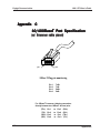
1
LAN•GOV User's Guide
Engage Communication, Inc.
9565 Soquel Drive
Ph 831.688.1021
www.engagecom.com
Aptos, California 95003
Fax 831.688.1421
Rev. 031704
Product Warranty
Seller warrants to Buyer that any unit shipped to Buyer,
under normal and proper use, be free from defects in
material and workmanship for a period of 12 months from
the date of shipment to Buyer. This warranty will not be
extended to items repaired by anyone other than the Seller
or its authorized agent. The foregoing warranty is exclusive and in lieu of all other warranties of merchantability,
fitness for purpose, or any other type, whether express or
implied.
Copyright Notice
Copyright ©2001-2004 Engage Communication, Inc.
All rights reserved. This document may not, in part or in entirety,
be copied, photocopied, reproduced, translated, or reduced to any
electronic medium or machine-readable form without first obtaining the express written consent of Engage Communication.
Restricted rights legend: Use, duplication, or disclosure by the
U.S. government is subject to restrictions set forth in subparagraph (c)(1)(ii) of the Rights in Technical Data and Computer
Remedies and Limitation of Liability
A. All claims for breach of the foregoing warranty shall Software clause in DFARS 52.227-7013 and in similar clauses in
be deemed waived unless notice of such claim is the FAR and NASA FAR Supplement.
received by Seller during the applicable warranty Information in this document is subject to change without
period and unless the items to be defective are re- notice and does not represent a commitment on the part of
turned to Seller within thirty (30) days after such Engage Communication, Inc.
claim. Failure of Seller to receive written notice of
any such claim within the applicable time period shall
be deemed an absolute and unconditional waiver by
buyer of such claim irrespective of whether the facts
giving rise to such a claim shall have been discovered
or whether processing, further manufacturing, other
use or resale of such items shall have then taken place.
B. Buyer’s exclusive remedy, and Seller’s total liability,
for any and all losses and damages arising out of any
cause whatsoever (whether such cause be based in
contract, negligence, strict liability, other tort or otherwise) shall in no event exceed the repair price of the
work to which such cause arises. In no event shall
Seller be liable for incidental, consequential, or punitive damages resulting from any such cause. Seller
may, at its sole option, either repair or replace defective goods or work, and shall have no further obligations to Buyer. Return of the defective items to Seller
shall be at Buyer’s risk and expense.
C. Seller shall not be liable for failure to perform its
obligations under the contract if such failure results
directly or indirectly from, or is contributed to by any
act of God or of Buyer; riot; fire; explosion; accident;
flood; sabotage; epidemics; delays in transportation;
lack of or inability to obtain raw materials, components, labor, fuel or supplies; governmental laws,
regulations or orders; other circumstances beyond
Seller’s reasonable control, whether similar or dissimilar to the foregoing; or labor trouble, strike,
lockout or injunction (whether or not such labor event
is within the reasonable control of Seller)
FCC Radio Frequency Interference Statement
This equipment has been tested and found to comply with the limits for a Class A digital device, pursuant to Part
15 of the FCC Rules. These limits are designed to provide reasonable protection against harmful interference
when the equipment is operated in a commercial environment. This equipment generates, uses, and can radiate
radio frequency energy and, if not installed and used in accordance with the instruction manual, may cause
harmful interference to radio communications. Operation of this equipment in a residential area is likely to cause
harmful interference in which case the user will be required to correct the interference at his own expense.
NOTE - Shielded ethernet cables must be used with the Engage LAN•GOV to ensure compliance with FCC
Part 15 Class A limits.
CAUTION – To reduce the risk of fire, use only No. 26 AWG or larger listed Telecommunication cables.
Equipment Malfunction
If trouble is experienced with an LAN•GOV, please contact the Engage Communication Service Center. If the
equipment is causing harm to the telephone network, the telecommunications service provider may request that
you disconnect the equipment until the problem is resolved.
Engage Communication Service Center:
Phone (U.S.)
831-688-1021
Fax
831-688-1421
Email
[email protected]
Web
www.engagecom.com
Engage Communication
LAN•GOV User's Guide
Table of Contents
Chapter 1 - Introduction...................................................... 6
LAN•GOV ................................................................................................................................ 6
About this Guide .................................................................................................................... 7
Chapter 2 - Installation QuickStart ................................... 8
LAV•GOV Basics .................................................................................................................... 8
Communication with the LAN•GOV ................................................................................... 9
LAN•GOV Cabling .............................................................................................................. 10
LAN•GOV Configuration Parameters .............................................................................. 10
Example 1: LAN•GOV Bi-Directional Rate Limiting at 21.616 Mbps ......................... 13
Chapter 3 - Installation of the LAN•GOV ....................... 15
Installation Requirements ................................................................................................ 15
Installing the Hardware ..................................................................................................... 15
Console Ports ...................................................................................................................... 16
Configuring the Engage LAN•GOV for the LAN ............................................................... 17
Status LEDs .......................................................................................................................... 17
Internal DIP Switches. ........................................................................................................ 18
Chapter 4 - Command Line Interface ............................. 19
Console Communication .................................................................................................. 19
Overview of Commands ..................................................................................................... 20
System Level Commands .................................................................................................. 22
SHOW Commands .............................................................................................................. 23
CONFIGURATION Commands ............................................................................................ 24
Config Interface Commands ............................................................................................. 25
4
Table of Contents
4
Engage Communication
LAN•GOV User's Guide
Chapter 5 - LAN•GOV : Configuration & Operation .... 29
LAN•GOV Installation Steps .............................................................................................
System Configuration ........................................................................................................
Rate Limiter Configuration ................................................................................................
Verifying the Connection ...................................................................................................
29
29
30
33
Chapter 6 - Troubleshooting ............................................ 34
Unable to Communicate with the LAN•GOV ................................................................. 34
Can’t communicate to the LAN•GOV - Console Port ..................................................... 36
Appendix A - LAN•GOV Specifications ........................... 37
Appendix B - LAN•GOV Switch Settings ....................... 38
Appendix C - 10/100BaseT Port Specification ........... 39
Appendix D - Console Port Information ....................... 40
Glossary - Terms and Concepts ....................................... 41
General Networking Terms ................................................................................................. 41
TCP/IP Networking Terms ................................................................................................. 42
Communication Link Definitions ..................................................................................... 43
5
Table of Contents
5
Engage Communication
LAN•GOV User's Guide
Chapter 1
Introduction
The LAN•GOV User's Guide provides the information users require to
install and operate the LAN•GOV developed and manufactured by
Engage Communication, Inc.
LAN•GOV
The LAN·GOV is used to interconnect Ethernet LANs through a data rate
governor. The data rate governor utilizes Time Division Multiplexing
based clocking to provide for Nx64, NxT1 and NxE1 bandwidth regulation
that is configurable from 64 kilobits up to DS3. Governing the WAN
bandwidth utilized by an Ethernet LAN enables the reservation of WAN
bandwidth for time sensitive real time connections such as those required
by Video Conferencing, Voice Over IP and TDM Over IP applications.
Transparent Interconnect
The LAN·GOV transparently monitors all the packet traffic on each of its
LAN segments to determine whether the packets it receives are to be
forwarded. The Ethernet MAC layer source addresses that are active on
each LAN are stored in a filtering database. Packets with a MAC destination that do not match a MAC address entry for the receiving port are
forwarded.
LAN Interface
• Two 10/100 BaseT Full/Half duplex Ethernet interfaces
• Autonegotiation or Configurable Speed and Duplex
6
Chapter 1: Introduction
Engage Communication
LAN•GOV User's Guide
About this Guide
Organization
Chapter 1 - Introduction provides an overview of the LAN•GOV User's
Guide as well as feature descriptions for the LAN•GOV.
Chapter 2 - QuickStart provides concise configuration examples to get the
experienced user up and running in the minimum time.
Chapter 3 - Installation covers the physical environment and connections
required when first installing the LAN•GOV.
Chapter 4 - Command Line Reference provides a command-by-command
description of the Engage CLI.
Chapter 5 - Configuration and Operation discusses the initial configuration and ongoing operation of the LAN•GOV.
Chapter 6 - Troubleshooting common problems occurring during installation and normal operation.
Appendices - LAN•GOV specifications, connector pinouts and crossover
wiring details.
Glossary - Routing, Telecommunication and TCP/IP terminology.
Intended Audience
This manual is intended for administrators of network and telecommunication systems. The technical content is written for readers who have basic
computer, telecommunication and networking experience.
It is important that any administrator responsible for the installation and
operation of Engage LAN•GOV products be familiar with IP networking
and data communication concepts and terms. These terms are central to
an understanding of LAN•GOV functionality, and are covered in the
Glossary section.
7
Chapter 1: Introduction
Engage Communication
LAN•GOV User's Guide
Chapter 2
Installation QuickStart
This QuickStart Chapter is intended for users who understand how they
want their LAN•GOV configured and only require the mechanics of
performing that configuration.
LAV•GOV Basics
The LANGOV has two 10/100BaseT Ethernet ports. They are labeled LAN
1 and LAN 2 on the LANGOV front panel. It is important to note that the
two interfaces are independent network processors and are configured
separately.
Each network processor has a console port. They are labeled Console 1
and Console 2 on the LANGOV front panel. Console 1 is used to configure the LAN 1 port and Console 2 is used to configure the LAN 2 port.
Initial communication with the IP•Tube is made through the Console ports
utilizing the Command Line interface detailed in Chapter 4: Command
Line Interface.
The Command Line Interface, identical for each network processor, refers
to a LAN1 interface and a RATELIMITER interface. The LAN1 interface
represents the Ethernet port on the network processor and the
RATELIMITER interface represents the internal rate limiting function.
Note that since the Command Line Interface is identical for both network
processors, when configuring the Ethernet port for LAN 2 from Console
Port 2 the Command Line Interface will refer to an interface named LAN1.
When reviewing the configuration information below, remember the
configuration must be made to both network processors.
8
Chapter 2: Installation QuickStart
Engage Communication
LAN•GOV User's Guide
Communication with the LAN•GOV
Console Port
Initial communication with the LAN•GOV is made through a Console port,
utilizing the Command Line interface detailed in Chapter 4: Command
Line Interface. Communication to a Console port should be set as: 9600
baud, 1 stop bit, no parity, 8 bit fixed.
There are two network processors on the LAN•GOV and each has a
Console port. Communication must be made to both Console ports for
correct operation of the LAN•GOV.
The Console port on the LAN•GOV is an RJ45 jack. The Console port is
configured as a DTE port. An RJ45/db9 adapter is provided with the
LAN•GOV which, in addition to providing a physical interface, performs
the null modem operation permitting direct connection to other DTE
equipment, such as the COM1 connection of a PC.
Once a serial connection between a workstation and a LAN•GOV Console
port is established and a carriage return <CR> is entered, a Login prompt
will appear.
The default login is: root.
Telnet
Once an IP address has been assigned to a LAN•GOV Ethernet interface,
the user can telnet into the LAN•GOV and continue configuration using
the Command Line Interface.
There are two network processors on the LAN•GOV and each has an
Ethernet port. An IP address must be assigned to the Ethernet interface
of both network processors to telnet into each network processor and
continue configuration.
Editing & Pasting Configurations
Users of the Command Line Interface have the option of editing standard
LAN•GOV configurations in text-only mode and pasting that configuration to the LAN•GOV.
Edit the desired configuration listing using a simple text editor. Connect
to a LAN•GOV network processor through Telnet or the Console port,
9
Chapter 2: Installation QuickStart
Engage Communication
LAN•GOV User's Guide
then enter the configuration mode with the command: config
Paste the edited text, comments and all, to the LAN•GOV, then issue the
command: save. The LAN•GOV network processor will reset and come up
with the new configuration.
Repeat the configuration, if necessary, for the other LAN•GOV network
processor.
To save an LAN•GOV network processor configuration, issue the
command: show config all and save the response listing to a file.
LAN•GOV Cabling
The LAN•GOV uses standard 10/100BaseT Ethernet cabling to connect to
an ethernet switch or hub. A crossover 10/100BaseT cable can be used
for direct connection to a single router, wireless radio or other ethernet
device.
LAN•GOV Configuration Parameters
The setup of the LAN•GOV involves configuration of the:
• LAN•GOV System Parameters
• Interface Specific (LAN1/RATELIMITER) Parameters
Examples are provided in this QuickStart and a complete description of all
commands is available in Chapter 4: Command Line Interface.
LAN•GOV System Parameters
System parameters include the LAN•GOV Hostname, the Ethernet IP
address, the default router, and Spanning Tree. Examples:
LAN•GOV Host Name
Provide a unique name for the LAN•GOV.
HOST NAME LANGovernor
Ethernet IP address
Assigning an IP address is required for telnet configuration or testing
connectivity with ping. For the ethernet interface, first specify INT LAN1.
10
Chapter 2: Installation QuickStart
Engage Communication
LAN•GOV User's Guide
IP ADDRESS aaa.bbb.ccc.ddd
LAN•GOV Default Router
If the telnet host resides on a different IP network from the LAN•GOV, a
default router must be specified.
IP DEFAULT-ROUTER aaa.bbb.ccc.ddd
Spanning Tree
Enables or disables IEEE 802.1 Spanning Tree bridging on both interfaces.
Turn this on if there is another bridge on the network with an IEEE 802.1
Spanning Tree.
LAN1 Interface Parameters
The LAN•GOV has LAN1 interface commands to set up the Ethernet port
for Auto-genotiation or duplex mode and bit rate.
Auto Negotiation
Enable or disable IEEE 802.3 Auto-negotiation on the Ethernet interface.
Warning: If the device connected to LAN1 uses Auto Negotiation and
LAN1 is configured to use full duplex without Auto Negotiation, the other
device may operate in half duplex mode by default and successful
operation cannot be guaranteed.
AUTONEGOTIATION {ON|OFF}
Duplex
Set the duplex mode for the Ethernet interface. This command only takes
effect when Auto-negotiation is configured to OFF. Warning: If the
device connected to LAN1 uses Auto Negotiation and LAN1 is configured to use full duplex without Auto Negotiation, the other device may
operate in half duplex mode by default and successful operation cannot
be guaranteed.
DUPLEX {HALF|FULL}
11
Chapter 2: Installation QuickStart
Engage Communication
LAN•GOV User's Guide
Speed
Set the line rate in Mbps for the Ethernet interface. This command only
takes effect when Auto-negotiation is configured to OFF.
SPEED {10|100}
RATELIMITER Interface Parameters
The RATELIMTER interface parameters determine the rate limiting
function of the LANGOV. The rate limiting function is configured for only
one direction, from the Ethernet receive of this network processor to the
Ethernet transmit of the other network processor. To configure the other
direction, you must configure the other network processor.
Rate Limit Mode
This determines the scaling factor by which to limit the committed
information rate across the LANGOV. For example, a RATELIMIT MODE
of NX64K will configure a committed information rate in 64Kbps increments. A RATELIMIT MODE of NXT1 will configure a committed
information rate in increments of a T1 rate or 1,544Kbps. A RATELIMIT
MODE of NXE1 will configure a committed information rate in increments
of an E1 rate or 2,048Kbps.
RATELIMIT MODE {NX64K | NXT1 | NXE1}
Rate Limit Factor
Choose a RATELIMIT FACTOR that when multiplied by the RATELIMIT
MODE gives the desired committed information rate.
RATELIMIT FACTOR NN
Example Configuration
LAN•GOV configuration is detailed in this section. The command line
configuration listing is shown for an example. The configuration commands are defined in Chapter 4: Command Line Interface.
12
Chapter 2: Installation QuickStart
Engage Communication
LAN•GOV User's Guide
Example 1: LAN•GOV Bi-Directional
Rate Limiting at 21.616 Mbps
Scenario
This sample configuration details an IP•Tube Rate Limiting at
21.616.Mbps. To complete the configuration, both the LAN 1 and LAN 2
ports are configured. The rate limiting is bi-directional, so the configuration is identical for each port.
Command Line Listing for Configuration of Port LAN 1
Host Name LANGovernor
Spanning Tree Off
Interface LAN1
Auto Negotiation On
IP Address 192.168.1.3/24
Interface RATELIMITER
Rate Limit Mode
NXT1
Rate Limit Factor
14
Command Line Listing for Configuration of Port LAN 2
Host Name LANGovernor
Spanning Tree Off
Interface LAN1
Auto Negotiation On
IP Address 192.168.1.4/24
Interface RATELIMITER
Rate Limit Mode
NXT1
Rate Limit Factor
14
13
Chapter 2: Installation QuickStart
Engage Communication
14
LAN•GOV User's Guide
Chapter 2: Installation QuickStart
Engage Communication
LAN•GOV User's Guide
Chapter 3
Installation of the LAN•GOV
This chapter provides details on the physical connections required for the
installation of Engage LAN•GOV equipment. Also covered is the initial
communication with the LAN•GOV.
References are made to the Configuration and Operation of the LAN•GOV
as well as to the Command Line Interface. These topics are covered in
detail in later chapters.
Installation Requirements
The use of Engage LAN•GOV systems to create a data rate governor
requires one LAN•GOV between the points to be governed.
A standard LAN•GOV package includes:
•
•
•
LAN•GOV unit
Console port adapter and cable
Power Converter (110 or 220 Vac input/15 Vac or 15 Vdc output)
Installing the Hardware
Locating the LAN•GOV
Site consideration is important for proper operation of the LAN•GOV. The
user should install the unit in an environment providing:
•
•
15
A well-ventilated indoor location
Access within six feet of a power outlet
Chapter 3: Installation
Engage Communication
LAN•GOV User's Guide
•
Two feet additional clearance around the unit to permit easy cabling
connection
As an option, the LAN•GOV can be mounted in a standard 19 inch
equipment rack (rack mounts are available from Engage)
Powering the LAN•GOV
Engage LAN•GOV units utilize an external power adapter, available in 110
VAC and 220 VAC versions, providing AC output.
The appropriate power adapter is provided with each unit.
• Ensure the power adapter is not connected to power.
• Plug the AC adapter into the circular rear panel POWER connector.
Connect the power adapter to an appropriate AC power outlet and check
the PWR LED on the front panel of the Engage LAN•GOV. The PWR LED
will be GREEN when the internal diagnostics have completed
Console Ports
All LAN•GOV models include two Console ports for configuration. The
Console ports may be used for serial communication from a local workstation, or for remote connection via a modem. The Console ports are labled
Console 1 and Console 2 on the front panel.
LAN•GOV models utilize an RJ45 jack for a Console port. A Console port
is configured as a DTE (data terminal equipment) port. This allows direct
connection to a DCE (data communication equipment) device such as a
modem. For connection to other DTE, such as a terminal or PC, a Null
Modem adapter is required.
An RJ45 to db9 adapter is provided with the LAN•GOV which, in addition
to providing a physical interface, performs the null modem operation
permitting direct connection to other DTE equipment, such as the COM1
interface of a PC.
Pinouts for a Console port, as well as Engage supplied adapters, are
provided in the Appendices.
Communication to a console port should be set for:
16
Chapter 3: Installation
Engage Communication
LAN•GOV User's Guide
9600 baud, 1 stop bit, no parity, 8 bit fixed
Once a serial connection between a workstation and a LAN•GOV Console
port is established and a carriage return <CR> is entered, a Login prompt
will appear.
The default login is: root.
Configuring the Engage LAN•GOV for the LAN
The LAN•GOV needs to be configured with a number of parameters for
proper operation in the network including:
• Ethernet autonegotiation
• Rate limiting functions
• for telnet or ping test: ethernet IP address, subnet mask, and default
gateway
The configuration procedure depends on the network environment in
which the LAN•GOV is to be installed.
Note: It is strongly suggested that you configure the LAN•GOV with its
unique network identity before making any ethernet connections for
configuration or ping test.
Ethernet Interface
Engage LAN•GOV systems utilize 10/100BaseT ethernet to connect to the
Local Area Network. Each system provides two 10/100BaseT interfaces on
the front panel for connection to an ethernet switch or hub using a
straight-thru ethernet patch cable. For direct connection to a PC or other
LAN device, the user should obtain a 10/100BaseT crossover cable.
10/100BaseT Ethernet cabling and crossover pinouts are provided in the
Appendices.
Status LEDs
Front panel LEDs provide System and Ethernet status.
17
Chapter 3: Installation
Engage Communication
LAN•GOV User's Guide
Power - The PWR LEDs will be green when the internal diagnostics have
completed.
Ethernet
FDX on indicates full duplex, off half duplex.
LNK on indicates good link status.
TD on indicates packet transmission.
RD on indicates packet reception.
Internal DIP Switches.
LAN•GOV systems contain an internal four position DIP Switch which is
accessible by removing the unit rear panel and sliding out the network
processor.
The default setting for all DIP switches is OFF.
Switch 1 - Powering cycling the unit with DIP Switch 1 ON forces the
LAN•GOV to return to factory default settings. Factory settings include
operation from Base Flash and deleting any download upgrades. Ensure
Switch 1 is returned to the OFF position after clearing an upgrade so
future upgrades can be performed successfully.
Switch 2 - On executes full diagnostics at power on. The default is off,
which reduces start up time.
Switch 3 - Not used.
Switch 4 - Not used.
18
Chapter 3: Installation
Engage Communication
LAN•GOV User's Guide
Chapter 4
Command Line Interface
Command Line access to a LAN•GOV network processor may be made via
a Telnet connection to the ethernet interface or via a serial connection to
the Console port.
Telnet, part of the TCP/IP Protocol Suite, provides a general communications facility defining a standard method of interfacing terminal devices to
each other. Any standard Telnet application can be used to communicate
to an Engage LAN•GOV provided there is IP connectivity between the
User Host and the LAN•GOV.
For communication through the Console port, standard terminal communication software is used. The console port may be used to communicate
with the LAN•GOV locally through a terminal, or remotely by dialing in
through a modem.
Console
Communication
Serial communication to the console port should be configured for
9600 baud, 1 stop bit, no parity, 8 bit fixed
The console port is an RJ45 jack and an appropriate cable and adapter are
provided with the LAN•GOV for use with standard 9 pin COM ports
The RJ45 console port is configured as a DTE (data terminal equipment)
port. This allows direct connection to a DCE (data communication
equipment) device such as a modem. For connection to other DTE, such
as a terminal, a Null Modem adapter is required.
19
Chapter 4: Command Line Interface
Engage Communication
LAN•GOV User's Guide
The RJ45 to DB9 adapter which is provided with the LAN•GOV serves this
null modem function, permitting direct connection to the COM1 interface
of most PCs.
Logging in to the LAN•GOV
A Telnet session is opened by providing the IP address of the LAN•GOV
network processor. On opening a CLI session, via Telnet or the Console
port, the login prompt requires entry of a login ID.
The default login ID: root.
The LAN•GOV is shipped with no password set. Passwords are set or
modified with the passwd command, detailed below.
Overview of Commands
The Engage CLI supports shorthand character entry. At most 3 characters are required for the parsing of the commands. For example: show
configuration can be entered as: sh con. The CLI is not case senstive.
Description of the commands uses both upper and lower case for syntax
definitions and examples.
A full description of the command line interface follows.
Categories
The command set can be divided into four categories:
General
Show
Config
Config Interface
Online Help
Included in the General commands is the HELP command, providing
information on the entire command set.
20
Chapter 4: Command Line Interface
Engage Communication
LAN•GOV User's Guide
Configuration Modes
For the Config and Config Interface commands, Engage employs a modal
approach. The user enters the Config mode, makes changes, then Saves
those changes. On Saving the changes the user leaves the Config mode.
The Config Interface mode, within the Config mode, is used to set
parameters for a specified interface. Once in the Configuration mode, the
user enters the INTERFACE command. All subsequent commands apply
to the specified interface.
The command prompt indicates the mode of operation:
name#
the single “#” indicates standard Telnet mode
name##
indicates the LAN•GOV is in the Config mode
name(lan1)## LAN•GOV is in Config Interface mode for interface LAN1
To move up one level, from Interface Config mode to Config mode, enter
the interface with no argument. To change between interfaces when in
Interface Config mode, specify the new interface. For example:
name(lan1)## interface ratelimiter
Syntax for Command Parameters
{} == one of the parameters in set is required
[ ] == one of the parameters in set is allowed (optional)
Show Config All
The SHOW CONFIG ALL command, outlined below, provides the means
to store and replay an entire configuration. Using a cut and paste
operation, configurations may be edited off-line and stored.
21
Chapter 4: Command Line Interface
Engage Communication
LAN•GOV User's Guide
System Level Commands
PASSWD
Allows setting or modifying the login password. The LAN•GOV ships
with no password set. On entering the passwd command, the user is
prompted to enter, and confirm, the new password.
BYE | QUIT | LOGOUT
Any of these commands will terminate the Telnet session. If you have
unsaved configuration changes, you will be prompted to save or discard
the new configuration.
RESET
Resets the LAN•GOV.
HELP [HELP | ALL | CONFIG | SHOW]
Provides Help information on a selected list of topics. Typing help with
no argument provides the Help summary screen which is the top-level list
of commands.
CLEAR {LAN1 | RATELIMITER}
Clears the port statistics on the selected port: Ethernet or Rate Limiter.
TERM NN
Allows the user to tailor the number of display lines to their terminal
screen size
PING {dest.address} [src.address] [number | spray]
Sends an ICMP ECHO message to the specified address. Any source
address from an interface on the IP•Tube can be used. This can be useful
to test routes across a LAN or WAN interface.
By default, only 1 message (packet) is sent. A numeric value can be
entered to send more than one message. Also, SPRAY can be used to
continually send messages until the ESC key is pressed.
22
Chapter 4: Command Line Interface
Engage Communication
LAN•GOV User's Guide
UPGRADE {TFTP Server Addr} {Filename}
TFTP (trivial file transfer protocol) provides a means for upgrading
LAN•GOV firmware in a TCP/IP environment. A TFTP upgrade may be
accomplished over the Internet from a user configured TFTP server.
Firmware upgrades and TFTP server software can be obtained from
Engage Technical Support ([email protected]).
Ensure IP connectivity between the LAN•GOV and the TFTP server by
pinging from one to the other. Then issue the upgrade command.
Example:
UPGRADE 157.22.234.129 langov237211.upg
Configure a local TFTP server with this file and upgrade with the local
server’s address.
Note that an LAN•GOV which is running an upgrade must go through two
resets when performing an upgrade. This may cause a Telnet connection
to drop. If this occurs, simply re-establish the Telnet connection.
SHOW Commands
SHOW [INTERFACE [LAN1 | RATELIMITER]] {INFO | STATISTICS}
Provides details on the LAN or rate limiter interface. If no interface is
specified, either the current interface per “interface” command will be
used, or all interfaces will be shown.
INFO
details the interface type and state
STATISTICS
lists the packets transmitted, received, etc.
The LAN1 statistics are packets transmitted and received on the LAN 1
(or 2) ethernet port. The RATELIMITER statistics are packets transmitted
and received on the internal inteface to the other network processor.
SHOW ROUTER provides general configuration and status information,
including the ethernet hardware address and the firmware version.
SHOW IP STATISTICS provides more detailed statistics on IP packets
only.
23
Chapter 4: Command Line Interface
Engage Communication
LAN•GOV User's Guide
SHOW CONFIG ALL provides a list of all configuration parameters. No
argument is the same as ALL. This list provides the basis for storing an
LAN•GOV configuration into a local text file. The full configuration can be
edited offline.
SHOW CONFIG INTERFACE [LAN1 | RATELIMITER]
If no interface is specified, either the current interface per the “interface”
command will be used, or all interfaces will be shown.
SHOW CONFIG IP [ALL] displays the IP default router
SHOW CONFIG ROUTER lists LAN•GOV Hostname, etc.
CONFIGURATION Commands
Engage employs a modal approach to LAN•GOV configuration. The user
enters the Configuration mode, makes changes, then Saves those
changes. On Saving the changes the user leaves the Configuration mode.
A further mode, within the Configuration mode, is used to set parameters
for a specified interface. Once in the Configuration mode, the user enters
the Interface command. All subsequent commands apply to the specified
interface.
The Telnet prompt indicates the mode of operation as follows:
name#
the single “#” indicates standard Telnet mode
name##
indicates the LAN•GOV is in the Config mode
name (lan1)## LAN•GOV is in Config Interface mode for interface LAN1
CONFIG
Enter the configuration mode, at which point the following commands
may be used:
SAVE
Save the changes and exit Configuration mode
END [SAVE]
Exit Configuration mode. The optional SAVE instructs the LAN•GOV to
24
Chapter 4: Command Line Interface
Engage Communication
LAN•GOV User's Guide
save configuration chnages.
RESTORE
Restores the current LAN•GOV configuration, ignoring any changes which have
been made during the current Telnet CONFIG session.
HOST NAME namestring
Provide a unique name for the LAN•GOV. The new host name does not take effect
until a save and reset is performed. For example:
HOST NAME LANGovernor
IP DEFAULT-ROUTER address
Enter the IP address of the default router or gateway. This must be an IP address
on the same network as the LAN•GOV ethernet interface.
Config Interface Commands
Configuration of the LAN•GOV involves setting parameters for the ethernet
(LAN1) interface and the rate limiter (RATELIMITER) interface. The user must
specify which interface is being configured with the command:
INTERFACE [LAN1 | RATELIMITER]
To move up one level, from Interface Config mode to Config mode, enter the
interface with no argument. To change between interfaces when in Interface
Config mode, specify the new interface. For example:
name(ratelimiter)## interface lan1
To move up one level, from CONFIG INTERFACE mode to CONFIG mode, enter the
command INTERFACE with no argument.
Ethernet Interface
AUTONEGOTIATION {ON | OFF}
Enable or disable IEEE 802.3 Auto-negotiation on the Ethernet interface. Warning:
If the device connected to LAN1 uses Auto Negotiation and LAN1 is configured
to use full duplex without Auto-Negotiation, the other device may operate in half
duplex mode by default and successful operation cannot be guaranteed.
25
Chapter 4: Command Line Interface
Engage Communication
LAN•GOV User's Guide
DUPLEX {HALF | FULL}
Sets the duplex mode for the Ethernet interface. This command only takes effect
when Auto-negotiation is configured to OFF. Warning: If the device connected to
LAN1 uses Auto-Negotiation and LAN1 is configured to use full duplex without
Auto-Negotiation, the other device may operate in half duplex mode by default and
successful operation cannot be guaranteed.
SPEED {10 | 100}
Sets the line rate in Mbps for the Ethernet interface. This command only takes
effect when Auto-negotiation is configured to OFF.
IP ADDRESS address[/mask]
The interface IP address and subnet mask are required for configuration with telnet
or connectivity tests with ping. The subnet mask can be entered in long or short
form. Examples:
IP ADDRESS 192.168.1.1/255.255.255.0
IP ADDRESS 192.168.1.1/24
IP BROADCAST [ONES | ZEROS | DIRECTED]
Assigns IP broadcast address for the Ethernet port. ONES assigns a broadcast
address of 255.255.255.255, which is the default on most networks. ZEROS assigns
a broadcast address of 0.0.0.0. DIRECTED assigns a broadcast address which is a
multicast of the network address for the Ethernet port. For example, if the network
address is 10.x.x.x, a directed broadcast address would be 10.255.255.255. Example:
IP BROADCAST ONES
Rate Limiter Interface
SPANNINGTREE {ON | OFF}
Enables or disables IEEE 802.1 Spanning Tree bridging on both interfaces. Turn
this on if there is another bridge on the network with an IEEE 802.1 Spanning Tree.
RATELIMIT MODE {NX64K | NXT1 | NXE1}
This determines the scaling factor by which to limit the committed information rate
26
Chapter 4: Command Line Interface
Engage Communication
LAN•GOV User's Guide
across the LANGOV. For example, a RATELIMIT MODE of NX64K will configure
a committed information rate in 64Kbps increments. A RATELIMIT MODE of
NXT1 will configure a committed information rate in increments of a T1 rate or
1,544Kbps. A RATELIMIT MODE of NXE1 will configure a committed information
rate in increments of an E1 rate or 2,048Kbps.
RATELIMIT FACTOR NN
Choose a RATELIMIT FACTOR that when multiplied by the RATELIMIT MODE
gives the desired committed information rate.
27
Chapter 4: Command Line Interface
Engage Communication
LAN•GOV User's Guide
Chapter 5
LAN•GOV : Configuration &
Operation
This chapter provides operational theory and configuration details for the
LAN•GOV.
LAN•GOV Installation Steps
The process of installing a LAV•GOV involves the following steps:
1.
2.
3.
4.
5.
6.
Planning for LAN•GOV interconect
Installing the IP•Tube hardware
System Configuration
Rate Limiter Configuration
Making 10/100BaseT ethernet cabling connections
Verifying the LAN•GOV connection
Planning and Installation
Planning includes site considerations, power requirements, and connection into a network. See Chapter 3: Installation for specific requirements.
System Configuration
The rate limiting functions of the LAN•GOV can be configured through
the Console ports. If a telnet session is to be used to configure the
29
Chapter 5: IP•Tube T1/E1 Configuration and Operation
Engage Communication
LAN•GOV User's Guide
LAN•GOV, then the Console ports must be used to configure an IP
address for each network processor so that a telnet session can be
initiated. In addition, system readiness and connectivity can be tested
with ping if an IP address is configured.
Initial configuration items include the hostname for the specific IP•Tube,
as well as a login password. The hostname is useful for identifying a
LAN•GOV when logged into a CLI session. See Chapter 4: Command
Line Interface for specific syntax requirements. Examples:
HOST NAME LANGovernor
PASSWD <cr>
An IP default router should be defined if the LAN•GOV being configured
is on a different IP network than the telnet host:
IP DEFAULT-ROUTER 172.16.1.1
The LAN•GOV IP address is configured:
INTERFACE lan1
IP ADDR 192.168.1.100/24
The configuration must be performed on each network processor in order
to obtain telnet and ping connectivity for that processor.
Rate Limiter Configuration
The rate limiter interface commands are configured by first selecting the
rate limiter interface.
INT RATELIMITER
Enable or disable IEEE 802.1 Spanning Tree bridging. Enable only if there
is another bridge on the network with an IEEE 802.1 Spanning Tree.
SPANNINGTREE {OFF | ON}
Determine the desired committed information rate across the LAN•GOV.
Then select a RATELIMIT MODE and RATELIMIT FACTOR that gives
the desired committed information rate. The committed information rate is
30
Chapter 5: IP•Tube T1/E1 Configuration and Operation
Engage Communication
LAN•GOV User's Guide
the RATELIMIT MODE times the RATELIMIT FACTOR, or CIR =
RATELIMIT MODE * RATELIMIT FACTOR.
RATELIMIT MODE {NX64K | NXT1 | NXE1}
• NX64K = 64Kbps
• NXT1 = 1,544Kbps
• NXE1 = 2,048Kbps
RATELIMITFACTORNN
Choose a RATELIMIT FACTOR that when multiplied by the RATELIMIT
MODE gives the desired committed information rate.
31
Chapter 5: IP•Tube T1/E1 Configuration and Operation
Engage Communication
IP•Tube User's Guide
A table is shown below with the various combinations of committed
information rate, RATELIMIT MODE, and RATELIMIT FACTOR.
RATELIM IT
M ODE
RATELIM IT
FACTOR
Committe d
Information
Rate (Kbps )
NX64K
1
64
NX64K
2- 30
128- 1,920
NX64K
31
1,984
NXT1
1
1,544
NXT1
2- 27
3,088- 41,688
NXT1
28
43,232
NXE1
1
2,048
NXE1
2- 20
4.096- 40,960
NXE1
21
43,008
Table 1 - Committed Information Rate Given Ratelimit Mode and Ratelimit
Factor
The rate limiting function is configured for only one direction, from the
Ethernet receive of one network processor to the Ethernet transmit of the
other network processor. To rate limit the transmit direction on one
network processor, you must configure the rate limit function of the other
network processor.
For example, if you wish to rate limit the Ethernet transmit of the network
processor on the LAN 2 port, you must configure RATELIMIT FACTOR
and RATELIMIT MODE for the network processor on the LAN 1 port.
3
2
Chapter 1: Introduction
Engage Communication
LAN•GOV User's Guide
LAN•GOV Cabling
The LAN•GOV uses standard 10/100BaseT Ethernet cabling to connect to
an Ethernet switch or hub.
Verifying the Connection
The LAN•GOV acts aa a bridge that passes Ethernet packets freely
between the LAN 1 and LAN 2 ports. The LAN•GOV connection can be
verified by testing connectivity between hosts that are sitting between
the LAN•GOV.
The LAN•GOV, if so configured, is also a device with IP addresses on the
LAN ports with telnet and ping capability. Ping tests to or from the
LAN•GOV can verify the LAN•GOV connection to the network.
The SHOW STATISTICS CLI command displays the number of packets
received and transmitted on a LAN port. The statistics can be used to
confirm or troubleshoot the LAN•GOV network connections.
33
Chapter 5: IP•Tube T1/E1 Configuration and Operation
Engage Communication
LAN•GOV User's Guide
Chapter 6
Troubleshooting
Communication and Network system are subject to problems from a
variety of sources. Fortunately, an organized troubleshooting approach
usually leads to the area of the problem in short order. It is essential to
distinguish between problems caused by the LAN (network system) and
the LAN•GOV configuration.
This troubleshooting chapter is structured with symptoms in the order the
user might encounter them.
Unable to Communicate with the LAN•GOV
The LAN•GOV is delivered in a configuration to function as a bridge with
a relatively high committed information rate. Therefore, it would be
expected that a LAN•GOV could be placed between any two points on a
network without disrupting the network. After a brief initialization period
while the LAN•GOV is learning about the network it will reach for forwarding state and the network should be functional.
Proceed through the following symptoms if you are unable to communicate through the LAN•GOV between points on the network (Telnet, Ping,
etc.).
Ethernet/General
Cause: Network is faulty
34
Chapter 8: Troubleshooting
Engage Communication
LAN•GOV User's Guide
Solution: Verify other elements of the network are good by swapping the
LAN•GOV with a single cable. The endpoints of the cable on each
LAN•GOV LAN port are replaced by the endpoints of the single cable.
Cause: Network Cabling is faulty
Solution: Check the LNK LEDs on both LAN•GOV LAN ports to confirm a
good connections. Check the LAN1 interface statistics to confirm the
error rate. Check the status LEDs on the equipment to which the
LAN•GOV LAN ports are connected. Determine if the cable is a 10/
100BaseT crossover cable. A crossover cable might not work with some
equipment, such as a hub.
Cause: LAN•GOV Ethernet Auto-negotiation is not configured correctly
Solution: If the device connected to the LAN•GOV LAN port is not
configured or capable of auto-negotiation, then configure LAN port LAN1
interface AUTONEGOTIATION OFF. The LAN1 interface SPEED and
DUPLEX mode should be set to match the configuration or capability of
the device.
If the device connected to the LAN•GOV is uses auto-negotiation and the
LAN•GOV is configured for DUPLEX FULL and AUTONEGOTIATION
OFF, the other device may operate in half duplex mode by default. The
LAN1 interface AUTONEGOTIATION should be set to ON if the other
device uses auto-negotiation.
Can’t Communicate with LAN•GOV
- Telnet, Ping
Cause: IP address is not set properly on the LAN•GOV
Solution: The Console Port, which requires an RJ45 to DB9 adapter,
provides direct access to the configuration of the LAN•GOV. Note: the
RJ45 Cable that connects to the Console Port must have 8 connections
pinned 1 to 1 (Typical Ethernet cables are only 4 wires). The Console port
utilizes the Command Line interface, detailed in Chapter 4: Command Line
Interface, and in the Appendices. Interface LAN1's IP Address must be in
the subnet of the computer that is attempting to access it locally.
Cause: Workstation not on the same subnet as the LAN•GOV
Solution: During an initial configuration of a LAN•GOV, communication
35
Chapter 8: Troubleshooting
Engage Communication
LAN•GOV User's Guide
should come from within the same net/subnet. With no default router, the
LAN•GOV will not be able to reply to communication off its own subnet.
Cause: IP stack on the workstation not configured
Solution: Ensure that other devices on the same LAN can be pinged, or
otherwise 'seen'.
Can’t communicate to the
LAN•GOV - Console Port
Cause: Baud Rate, Stop Bits, etc. set wrong on communication application
Solution: Ensure the communication software is configured for a fixed,
asynchronous data rate of 9600 bps, 1 stop bit, no parity, 8 bit fixed and
that the Flow control is set to none.
Cause: Transmit and Receive Data swapped
Solution: The console port RJ45 to DB9 adapter is configured as a DCE
(data communication equipment) port. For connection to other DCE, such
as a modem, a Null Modem adapter is required. Note: the RJ45 Cable that
connects to the Console Port must have 8 connections pinned 1 to 1
(Typical Ethernet cables are only 4 wires).
36
Chapter 8: Troubleshooting
Engage Communication
LAN•GOV User's Guide
Appendix A
LAN•GOV Specifications
Ethernet Ports
•
10/100BaseT Full Ethernet
•
TCP/IP, ICMP
•
•
64Kbps to 43,232K rate limiting range
Configurable in 64K, 1,544K, and 2,048K bps increments
•
External 24 Volts AC, 1Amp, with standard AC plug. International
power supplies available.
•
•
•
Standard 19 inch rack mount kit available
Dimensions: 9.0 x 7.3 x 1.63 inches
Weight: approximately 2 lbs., excluding external power adapter.
LAN Protocol
Rate Limter
Power Supply
Physical
37
Appendices
Engage Communication
LAN•GOV User's Guide
Appendix B
LAN•GOV Switch Settings
LAN•GOV systems contain a four position DIP Switch which is accessible
by removing the unit rear panel and sliding out the motherboard.
The default setting for all DIP switches is OFF.
Switch 1
Powering cycling the unit with DIP Switch 1 ON forces the LAN•GOV to
return to factory default settings. Factory settings include operation from
Base Flash and deleting any download upgrades. Ensure Switch 1 is
returned to the OFF position after clearing an upgrade so future upgrades
can be performed successfully.
Switch 2
On executes full diagnostics at power on. The default is off, which
reduces start up time.
Switch 3
Not used.
Switch 4
Not used.
38
Appendices
Engage Communication
LAN•GOV User's Guide
Appendix C
10/100BaseT Port Specification
(w/ Crossover cable pinout)
pin 1
pin 8
10BaseT Plug pin numbering
Pin 1
Pin 2
Pin 3
Pin 6
TxD+
TxDRxD+
RxD-
For 10BaseT Crossover (allowing connection
directly between two 10BaseT devices) wire:
(TD+)
(TD-)
(RD+)
(RD-)
39
Pin 1
Pin 2
Pin 3
Pin 6
to Pin 3 (RD+)
to Pin 6 (RD-)
to Pin1 (TD+)
to Pin 2 (TD-)
Appendices
Engage Communication
LAN•GOV User's Guide
Appendix
D
Console Port Information
RJ45 Console Port Pinout
RJ45 pin
Signal Name
3
6
1
8
4
2
TxData
RxData
RTS
CTS
Gnd
DTR
RJ45/db9F Null Modem Adapter
RJ45 pin
3
6
1
4
2
40
db9pin
2
3
8
5
6
Appendices
Engage Communication
LAN•GOV User's Guide
Glossary
Terms and Concepts
Before using the LAN•GOV, you should be familiar with the terms and
concepts that describe TCP/IP. If you are experienced with internet
routers, these terms may already be familiar to you.
General Networking Terms
Network
A network is a collection of computers, server devices, and communication devices connected together and capable of communication with one
another through a transmission medium.
Internet
An internet is any grouping of two or more networks connected by one or
more internet routers.
Addresses
Transmitting information in a network system is made possible by an
addressing scheme that identifies the sender and destination of the
transmission, using network and node addresses. Data is transmitted to
and from these addresses in the form of packets.
Node
Device on the network
41
Glossary
Engage Communication
LAN•GOV User's Guide
TCP/IP Networking Terms
FTP
File Transfer Protocol gives users the ability to transfer files between IP
hosts. It uses TCP to provide connection initiation and reliable data
transfer.
Host
A computer with one or more uses that can act as an endpoint of communication if it has TCP/IP.
ICMP
Internet Control Message Protocol provides a means for intermediate
gateways and hosts to communicate. There are several types of ICMP
messages and they are used for several purposes including IP flow
control, routing table correction and host availability.
IP
Internet Protocol which routes the data.
PING
Packet InterNet Groper is a program which uses ICMP echo request
message to check if the specifies IP address is accessible from the current
host.
Port
A Destination point used by transport level protocols to distinguish
among multiple destinations within a given host computer.
SubNet Address
An extension of the IP addressing scheme which enables an IP site to use
a single IP address for multiple physical networks. Subnetting is applicable when a network grows beyond the number of hosts allowed for the
IP address class of the site.
42
Glossary
Engage Communication
LAN•GOV User's Guide
TCP
Transmission Control Protocol ensures reliable, sequential, delivery of
data. TCP at each end of the connection ensures that the data is delivered
to the application accurately, sequential, completely and free of duplicates. The application passes a stream of bytes to TCP which breaks it
into pieces, adds a header, forming a segment, and then passes each
segment to IP for transmission.
Telnet
The TCP/IP standard protocol for remote terminal connection service. A
user can telnet from the local host to a host at a remote site.
Communication Link Definitions
Data Communication Equipment (DCE)
This interfaces to the communication service’s transmission/reception
medium, and includes T1 Voice/Data Multiplexors, 64/56 Kilobit DSU/
CSUs, and Fiber Optic Modems. The DCE provides the transmit and
receive data pathways, along with their synchronous clocking signals,
that are used by the Engage Router’s DTE interface for full duplex
communication between the remotely interconnected networks.
Data Terminal Equipment (DTE)
This equipment, such as an Engage Router, attaches to the terminal side
of Data Communication Equipment.
Data Terminal Ready (DTR)
Prepares the DCE to be connected to the phone line, then the connection
can be established by dialing. Enables the DCE to answer an incoming
call on a switched line.
43
Glossary