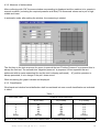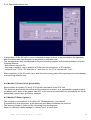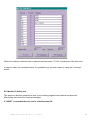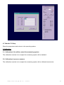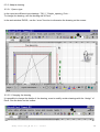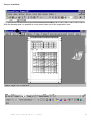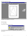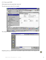
1
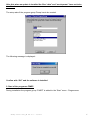
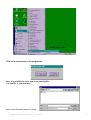
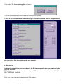
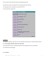
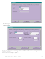
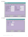
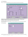
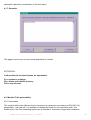
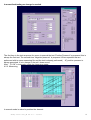
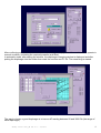
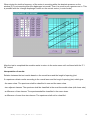
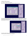
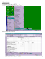
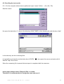
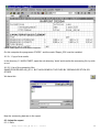
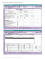
Software S- auto FIMEP for AEV test in accordance to EN. 1 INTRODUCTION This is a manual of the software specially developed for use with the type P100S machine. The software is divided in two parts; one part to measure and pilot the machine and a second part who uses Excel to produce a report. The software made it possible to use the machine in manual or semi-automatic mode. For an computer already programmed go to chapter 2 “Starting the programme FIMEP”. 2 Software S-auto FIMEP in accordance to EN. 0. Description of the software Fimep . . . . . . . . . . . . . . . . . . . . . . . . . . . . . . . . . . . . . . . . . . . . . . . . 4 1. New installation or update . . . . . . . . . . . . . . . . . . . . . . . . . . . . . . . . . . . . . . . . . . . . . . . . . . . . . . 4 2. Start of the program FIMEP . . . . . . . . . . . . . . . . . . . . . . . . . . . . . . . . . . . . . . . . . . . . . . . . . . . . . 7 3. Main menu . . . . . . . . . . . . . . . . . . . . . . . . . . . . . . . . . . . . . . . . . . . . . . . . . . . . . . . . . . . . . . . . . . 8 4. Modules . . . . . . . . . . . . . . . . . . . . . . . . . . . . . . . . . . . . . . . . . . . . . . . . . . . . . . . . . . . . . . . . . . . . 9 4.1. F1 Description . . . . . . . . . . . . . . . . . . . . . . . . . . . . . . . . . . . . . . . . . . . . . . . . . . . . . . . . . 9 4.1.1. General . . . . . . . . . . . . . . . . . . . . . . . . . . . . . . . . . . . . . . . . . . . . . . . . . . . . . . . 9 4.1.2. Properties . . . . . . . . . . . . . . . . . . . . . . . . . . . . . . . . . . . . . . . . . . . . . . . . . . . . 10 4.1.3. Elements . . . . . . . . . . . . . . . . . . . . . . . . . . . . . . . . . . . . . . . . . . . . . . . . . . . . . 11 4.1.4. Glazing . . . . . . . . . . . . . . . . . . . . . . . . . . . . . . . . . . . . . . . . . . . . . . . . . . . . . . 11 4.1.5. Classification . . . . . . . . . . . . . . . . . . . . . . . . . . . . . . . . . . . . . . . . . . . . . . . . . . 12 4.1.6. Environment . . . . . . . . . . . . . . . . . . . . . . . . . . . . . . . . . . . . . . . . . . . . . . . . . . 12 4.1.7. Remarks . . . . . . . . . . . . . . . . . . . . . . . . . . . . . . . . . . . . . . . . . . . . . . . . . . . . . 13 4.2. Module F2 Air permeability . . . . . . . . . . . . . . . . . . . . . . . . . . . . . . . . . . . . . . . . . . . . . . 13 4.2.1 Parameters 13 4.2.2 Measuring 14 4.3. Module F3 Wind resistance . . . . . . . . . . . . . . . . . . . . . . . . . . . . . . . . . . . . . . . . . . . . . 17 4.3.1. Measure of deformation parameters . . . . . . . . . . . . . . . . . . . . . . . . . . . . . . . . 17 4.3.2. Measure of deformation . . . . . . . . . . . . . . . . . . . . . . . . . . . . . . . . . . . . . . . . . 18 4.3.3. Classification 18 4.3.4. Repeated pressure test 19 4.4. Module F4 Control of air permeability . . . . . . . . . . . . . . . . . . . . . . . . . . . . . . . . . . . . . . 19 4.5. Module F5 Water tightness . . . . . . . . . . . . . . . . . . . . . . . . . . . . . . . . . . . . . . . . . . . . . . 19 4.6. Module F6 Safety test . . . . . . . . . . . . . . . . . . . . . . . . . . . . . . . . . . . . . . . . . . . . . . . . . . 20 4.7. Module F10 Stop . . . . . . . . . . . . . . . . . . . . . . . . . . . . . . . . . . . . . . . . . . . . . . . . . . . . . 21 5. Calibration . . . . . . . . . . . . . . . . . . . . . . . . . . . . . . . . . . . . . . . . . . . . . . . . . . . . . . . . . . . . . . . . . 21 5.1. Calibration of the flowmeters . . . . . . . . . . . . . . . . . . . . . . . . . . . . . . . . . . . . . . . . . . . . 21 5.2. Calibration of the pressure sensors . . . . . . . . . . . . . . . . . . . . . . . . . . . . . . . . . . . . . . . 21 6. Report of tests . . . . . . . . . . . . . . . . . . . . . . . . . . . . . . . . . . . . . . . . . . . . . . . . . . . . . . . . . . . . . . 6.1. Open the report-type in EXCEL . . . . . . . . . . . . . . . . . . . . . . . . . . . . . . . . . . . . . . . . . . 6.2. Recalling the test results . . . . . . . . . . . . . . . . . . . . . . . . . . . . . . . . . . . . . . . . . . . . . . . . 6.2.1. On the computer where the tests are performed . . . . . . . . . . . . . . . . . . . . . . 6.2.2. Test report on an other computer . . . . . . . . . . . . . . . . . . . . . . . . . . . . . . . . . . 6.2.2.1. Copy of test results . . . . . . . . . . . . . . . . . . . . . . . . . . . . . . . . . . . . . . 6.2.2.2. Use of the measuring files . . . . . . . . . . . . . . . . . . . . . . . . . . . . . . . . . 6.3. Adapt the report . . . . . . . . . . . . . . . . . . . . . . . . . . . . . . . . . . . . . . . . . . . . . . . . . . . . . . 6.3.1. Date . . . . . . . . . . . . . . . . . . . . . . . . . . . . . . . . . . . . . . . . . . . . . . . . . . . . . . . . . 6.3.2. Changing the remarks . . . . . . . . . . . . . . . . . . . . . . . . . . . . . . . . . . . . . . . . . . . 6.3.3. Adapt a window drawing . . . . . . . . . . . . . . . . . . . . . . . . . . . . . . . . . . . . . . . . . 6.3.3.1. Open the type drawings . . . . . . . . . . . . . . . . . . . . . . . . . . . . . . . . . . . 6.3.3.2. Change the drawing . . . . . . . . . . . . . . . . . . . . . . . . . . . . . . . . . . .. . 6.4. Print a report with a drawing . . . . . . . . . . . . . . . . . . . . . . . . . . . . . . . . . . . . . . . . . . . . . 6.5. Save a report . . . . . . . . . . . . . . . . . . . . . . . . . . . . . . . . . . . . . . . . . . . . . . . . . . . . . . . . 6.5.1. Close EXCEL . . . . . . . . . . . . . . . . . . . . . . . . . . . . . . . . . . . . . . . . . . . . . . . . . 6.5.2. Save as in EXCEL . . . . . . . . . . . . . . . . . . . . . . . . . . . . . . . . . . . . . . . . . . . . . . Fimep S-auto soft_UK ver 6.0 - 03/2011 22 22 23 23 24 24 24 25 25 25 26 27 28 28 29 30 32 3 0. Description of the Fimep software. The software is multi platform and works under Windows 95 / 98 / ME / 2000 and NT and includes two systems: a measuring system under visual basic and an report system under “EXCEL” . 1. New installation or update of an old version The software is provided on CD-ROM or USB stick, the installation starts automatic. If it don’t start go to the “setup.exe” file in the “Installation” menu. : In the zone ”Open :” type the letter of the drive followed by (:) et setup. Example: E:setup And “OK” Fimep S-auto soft_UK ver 6.0 - 03/2011 4 After the reading follows: You has to close all Windows programmes and confirm with “OK” Here is the possibility to change the file where the programme is saved. Normally it is set to install the programme in the directory C:\AWW FIMEP. If nothing has to be changed we have: Push the button Fimep S-auto soft_UK ver 6.0 - 03/2011 5 After this when an update is installed the files “data” and “mach param” have not to be overitten! The setup asks if the program group Fimep has to be created. The following message is displayed: Confirm with “OK” and the software is installed. 2. Start of the programm FIMEP During installation the program group “FIMEP” is added to the “Start” menu - Programmes Fimep S-auto soft_UK ver 6.0 - 03/2011 6 Confirm once and: This is the start screen of the programme: Here it is possible to use a new or an existing file: If a new file is selected then: Here a new file name has to be used. Fimep S-auto soft_UK ver 6.0 - 03/2011 7 If the option “F2 Open existing file” is chosen: Then the same window is opened and the existing file is opened. If there is no communication with the test rig F8 should be pressed and the com port set to the right value. See description on the user manual. 3. Main menu In the main menu all the tests according to the European normalisation are displayed in the order of execution. The main menu always opens in automatic mode! To select manual mode, mark with on the “MANUAL Control”. Each time a test sequence is performed a is marked. Fimep S-auto soft_UK ver 6.0 - 03/2011 8 This is an aid to memorise witch tests are completely performed. All measuring results are registered in the measuring file after each test. The language can be changed by use of the [Ctrl+F12]. A main menu after a partial test: 4. Modules The different modules in the main menu are accessible by mouse click or with the function buttons. 4.1. F1 Description (Details of the item under test) This module permit to put a complete description of the window under test in the data file. The module has several pages: 4.1.1. General Fimep S-auto soft_UK ver 6.0 - 03/2011 9 The other pages : 4.1.2. Properties Here the outer dimensions and the length of joint are to fill in; the dimension of opening parts are not needed for calculation. For fixed frames the length of joint = 0 . Fimep S-auto soft_UK ver 6.0 - 03/2011 10 4.1.3. Elements 4.1.4. Glazing Fimep S-auto soft_UK ver 6.0 - 03/2011 11 4.1.5. Classification This is a very important page because it sets the maximum of test for the wind resistance. Normally for the air permeability we always go to 600 Pa (C4); for the wind resistance however it is important to choose the level of performance asked according to the EN 12210 classification. In automatic mode the machine wont go beyond the selected level! For the water infiltration test the method A is most used (spray bar at 24) and we have to select the maximum pressure. 4.1.6. Environment Here the temperature and atmospheric pressure are needed for calculation; the relative air humidity is Fimep S-auto soft_UK ver 6.0 - 03/2011 12 optional but asked by normalisation in the test report. 4.1.7. Remarks This page is used to put a more textual description if needed. ATTENTION! In all module the function buttons are operational: F1 to memorise readings. F2 to delete and initialise memory. F10 to stop the test. 4.2. Module F2 Air permeability 4.2.1 Parameters This module defines the different levels of pressure te measure in accordance to EN 1026 “Air permeability - test method”. It is possible to change the levels for not normalised tests. The coefficients of the flow measuring system are accessible to eventually change after calibration. Fimep S-auto soft_UK ver 6.0 - 03/2011 13 In normalised testing no change is needed. The first time in the test sequence the menu is opened the test “Positive Pressure” is proposed; this is always the first test. The second time “Negative pressure” is proposed. When repeated test are performed with te same measuring file and the test is already performed ( ) positive pressure is always presented, it is to change in the pull- down menu! After “ F1 OK” in automatic mode the measuring starts: 4.2.2. Measuring In manual mode is asked to position the element: Fimep S-auto soft_UK ver 6.0 - 03/2011 14 After confirming with “OK” the same window as preceding is displayed and the machine is to operate in manual condition ( selecting the required pressure and Start) In automatic mode, after setting the window, the diaphragm changing window is displayed and after putting the diaphragm into the holder then mark the number and F1 Ok. The measuring is started. The way to choose a good diaphragm is to have a dP reading between 50 and 3000 Pa (the range of each diaphragm). Fimep S-auto soft_UK ver 6.0 - 03/2011 15 When during the test the frequency of the motor is mounting while the absolute pressure on the window (P) is not mounting then the diaphragm is to small. Then it is usual to put a greater one in. This is possible with the “change diaphragm” button on the control centre ( in auto mode). After the test is completed the machine waits to return to the main menu until confirmed with the “F1 Ok” button! Interpretation of results: Relation between the test results based on the overall area and the lenght of opening joint. If a specimen obtain results according to the overall area and the lengt of opening joint, which give: - the same class. The specimen shall be classified in one and the same class - two adjacent classes. The specimen shall be classified in the most favourable class (with lower rate) - a difference of two classes. The specimenshall be classified in the mean class - a difference of more than two classes. The specimen shall not be classified. Fimep S-auto soft_UK ver 6.0 - 03/2011 16 4.3. Module F3 Wind resistance 4.3.1. Measure of deformations parameters. Measuring is performed by three gauge measurement relative to the frame. This module defines the different levels of pressure te measure in accordance to EN 1211 “Resistance to wind load - test method”. It is possible to change the levels for not normalised tests. The pressure levels beyond the asked performance (§ 4.1.5.) are not reached. The length between the two external measuring points is to put in mm. In automatic mode the machine starts the positioning and then the measuring. In manuel mode the “positioning” window is displayed. Fimep S-auto soft_UK ver 6.0 - 03/2011 17 4.3.2. Measure of deformations After confirming with “OK” the same window as preceding is displayed and the machine is to operate in manual condition ( selecting the required pressure and Start) The measured values are to put in high, middle and lower. In automatic mode, after setting the window, the measuring is started. The first time in the test sequence the menu is opened the test “Positive Pressure” is proposed; this is always the first test. The second time “Negative pressure” is proposed. When repeated test are performed with te same measuring file and the test is already performed ( ) positive pressure is always presented, it is to change in the pull- down menu! While measuring the graph is drawn and displayed. 4.3.3. Classification Wind loads and relative frontal deflection shall be combined into one overall classification as indicated in table 1 Table 1 Wind load class 1 2 3 4 5 Exxxx Relative frontal deflection A (<1/150) B (<1/200) C (<1/300) A1 A2 A3 A4 A5 AExxxx B1 B2 B3 B4 B5 BExxxx C1 C2 C3 C4 C5 CExxxx NOTE: In the resistance to wind load classification the number refers to the wind load class. Fimep S-auto soft_UK ver 6.0 - 03/2011 18 4.3.4. Repeated pressure test In accordance to the EN 12211 norm a repeated pressure test has to be executed on the specimen after the deformation test and prior to the control air infiltration test. The test specimen shall be subjected to 50cycles including negative and positive pressures, with the following features: - test pressure equal to P2; - first step is negative, next is positive as is the last of the sequence of 50 impulses; - variation from - P2 to + P2 shall take ± 7 with time 0 ± 3 s; P2 is maintained ± 7 sec. After completion of the 50 cycles, open and close the moving parts of the specimen and note damage or functioning defects if any. 4.4. Module F4 Control of air permeability Same module as module F2 (see § 4.2) but with calculation of the 20% limit. The specimen shall remain functional and the maximum increase, in air permeability caused by wind resistance tests, shall not be greater than 20% of the maximum permissible air permeability for the air permeability classification previously obtained. 4.5. Module F5 Water tightness This module is in accordance to the EN 1027 “Watertightness - test method” It is possible to ad a description at the pressure level where infiltration has occured. The amount of water in l/min and the remaining time are displayed. When no infiltration (water leakage) is viewed “none” is mentioned. Fimep S-auto soft_UK ver 6.0 - 03/2011 19 When the maximum desired level is reached then the button “F1 OK” is pushed and the test ends. In case of other, not normalised tests, it is possible to go on much faster by using the “next step” button. 4.6. Module F6 Safety test The specimen shall be subjected to one cycle including negative and positive test pressure. After safety test record the eventual damages. If “NONE” is recorded then the test is considered as OK. Fimep S-auto soft_UK ver 6.0 - 03/2011 20 4.7. Module F10 Stop. Stops the programme and returns to the operating system. 5. Calibration 5.1. Calibration of the airflow, water flow measuring system The calibration consists in to compare the measuring system with a standard. 5.2. Calibration of pressure sensors The calibration consists in to compare the measuring system with a calibrated manometer. Fimep S-auto soft_UK ver 6.0 - 03/2011 21 6. Report of tests 6.1. Open the report-type in EXCEL In “Start” , “Programmes” and Fimep open “Report”. Then an empty mask is opened: Fimep S-auto soft_UK ver 6.0 - 03/2011 22 6.2. Recalling the test results 6.2.1. On the computer where test are performed: open “macro” (Extra ....) Or [ Alt + F8]. Start the macro: He opens the hard drive C ; there is the directory AWW FIMEP; in this directory the sub directory “data” In thie directory are the measuring files. It is possible to ad a button on the button bar in EXCEL:” See the “help” file in Excel. “ who opens the macro and works with it. When the measuring file is opened the test report is completed with the measures. A test report always named “Report3_EN1 is created. Therefore it is recommended to change the name and save it. Fimep S-auto soft_UK ver 6.0 - 03/2011 23 6.2.2. Test report on a different computer. On this computer the programme “EXCEL” and the mask “Report_EN” must be installed. 6.2.2.1. Copy of test results In the directory C:\ AWW FIMEP; open the sub directory “data” and transfer the measuring file, by stick or net. 6.2.2.2. Use of the measuring files SAME PROCEDURE AS § 6.2.1. BUT NOW SEARCH THE FILES BY OPENING DE STICK OR OTHER. We have this Now the measuring data are in the report: 6.3. Adapt the report 6.3.1. Date Fimep S-auto soft_UK ver 6.0 - 03/2011 24 The system date is always used; it can be modified: Fimep S-auto soft_UK ver 6.0 - 03/2011 25 6.3.3. Adapt a drawing. 6.3.3.1. Open a type. In the report are different type drawings “DK_L”, Simple_opening_G etc.... To change the drawing, use the drawing aid in Excel. In the work window EXCEL, use the “zoom” function to dimension the drawing on the screen: 6.3.3.2. Changing the drawing It is possible to change the details of the drawing, even to modify certain drawings with the “design” of Excel. See the buton on the toolbar. Fimep S-auto soft_UK ver 6.0 - 03/2011 26 Sample of tool bar; With the drawing aids it is possible to move some items out of the impression zone. Fimep S-auto soft_UK ver 6.0 - 03/2011 27 6.4. Print the report with a drawing Print sample ; to print a drawing go to print previeuw. 6.5. Save the report 6.5.1. Closing EXCEL Closing EXCEL the following question is asked: If one would save the report under the name “Report_EN1" ; there is no problem. If a second file is opened you have to save it under a different name.If the file need not to be saved then answer No. Fimep S-auto soft_UK ver 6.0 - 03/2011 28 6.5.2. Save under EXCEL Sif the report has to be saved; then “save it as” The pull down menu under “file” is needed. The computer stations are opened. Depending where you want to save it is possible to open all the media on the computer with: Fimep S-auto soft_UK ver 6.0 - 03/2011 29