1
NT-IP
Enhanced ISDN Network Termination
with one RS-232 and two analog ports
Installation MANUAL
SW REVISION 2.0
rd
DATE: December 23 , 1998
Aethra NT-IP User's Manual sw rev. 2.0
safety rules
The electrical supply used for this equipment involves LETHAL voltage levels. If objects or liquids penetrate
inside the workstation, immediately disconnect the supply cable. Before using the equipment again, have
it checked by qualified personnel.
DO NOT ACCESS INTERNAL PARTS WHICH ARE NORMALLY PROTECTED WITH PANELS FIXED WITH SETSCREWS.
BEFORE ANY OPERATION ALWAYS CHECK THAT THE ELECTRICAL SUPPLY HAS BEEN COMPLETELY AND EFFICIENTLY DISCONNECTED.
If the user is not able to restore the regular functioning, he must refer to qualified service personnel.
In case of fire, avoid by all means using water to extinguish it.
warnings
Handling of devices which are subject to static electricity
Many of the components used in the workstation are subject to damage by electrostatic discharge. When
handling connectors between different devices, disconnect the electrical supply using the switch located in
the back part of the system.
Failure to do so could cause permanent damage to the equipment.
this product complies with the EEC Directive 89/336 relating to Electromagnetic compatibility and to
the EEC Directive 73/23 (Low Voltage) concerning safety standards.
2/59
Aethra NT-IP User's Manual sw rev. 2.0
Glossary
The following terms will be used throughout this document:
ISDN
the Integrated Service Digital Network
PSTN or POTS
the standard analog phone network (Plain Old Telephone System)
basic rate access (BRA)
the standard ISDN access, with one signalling and two user channels
user bus, "S" or "S/T" bus
a four wire bus used to connect user terminals to the NT1
multipoint access
an ISDN basic access configured to provide support for up to 8 terminals on the user bus
point-to-point access
an ISDN basic access configured to provide support for a single terminal on the user bus
ISDN terminal
a generic terminal designed for connection to the S bus such as an ISDN phone, a videophone, a
terminal adapter, a group 4 fax, a PC equipped with an ISDN board, etc.
analog terminal,
POTS terminal
a generic terminal designed for the connection to the PSTN such as a phone, a modem, a fax, a key
system, an answering machine, etc.
POTS port or a/b port
one of the two interfaces provided by the NT-IP for connection to analog terminals
normal conditions
the a.c. supply is available and adequate power is provided to the NT-IP
emergency conditions
the a.c. supply is not available and the NT-IP uses the remote power from the exchange to guarantee a
(restricted) service to the user
local loop
the telephone line, consisting of a copper pair that connects the NT-IP to the ISDN exchange
3/59
Aethra NT-IP User's Manual sw rev. 2.0
1
INTRODUCTION
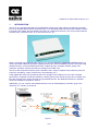
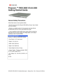
The NT-IP is a network termination for the ISDN basic rate access, which adds to the features commonly
found in a standard ISDN network termination (NT1), two standard telephone ports and an RS232 interface
to provide a fully digital, fast and reliable connection to a PPP terminal server, such as an Internet Service
Provider (ISP), a remote access, an e-mail access server, etc.
When connecting to the ISDN through a NT-IP, you can use ISDN basic telephony services without any
need to purchase additional equipment (digital phones and/or terminal adapters), and you can keep using
standard devices, such as standard phone sets, cordless phones, analogue modems, group 3 fax
machines, automatic answering machines, analogue micro PBX’s etc.
The NT-IP also supports emergency phone operation and a range of supplementary telephony services
(call hold, call waiting, 3-party conferencing, call forwarding, etc.).
A fully digital data service is provided by the NT-IP straight to the COM port of a PC with unrivalled
performance compared to analogue modems, including sub-second call set-up times and a virtually error
free data channel to the service provider at a guaranteed bit rate. No additional hardware or software
need to be installed to operate the service.
Additionally, you can connect native ISDN terminals, such as videotelephony terminals, group 4 fax
machines, etc., directly on the S-bus.
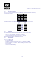
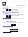
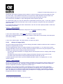
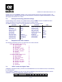
Figure 1
4/59
Aethra NT-IP User's Manual sw rev. 2.0
1.1
Feature Summary
Standard NT1
-
2-wire interface on the U reference point
-
4-wire user bus on the S/T reference point
POTS ports
–
–
–
–
pulse and/or tone dialling, ringing signal, metering pulse generation
PCM speech coder/decoder, according to G.711, A-law
generation of Calling Line ID messages
available in emergency conditions (mains off)
RS232 port
–
–
–
–
–
–
Internet Access on a single B-channel or on both B-channels using the multilink PPP (MP) protocol
Bandwidth on Demand (BOD)
Bandwidth Allocation Protocol and Bandwidth Allocation Control Protocol (BAP/BACP)
Peer to peer communication according to ITU-T V.120 and V.110 recommendations
Enhanced AT command
automatic bit rate recognition
Maintenance
–
–
local system and port configuration and diagnostics
local and remote download of firmware upgrades
5/59
Aethra NT-IP User's Manual sw rev. 2.0
2
2.1
SYSTEM OPERATION
Power Supply
An external a.c. adapter generates low-voltage power required for internal operation and to provide
phantom power to the S bus.
When mains power is not available (restricted power mode), the NT-IP uses the power fed by the ISDN
exchange through the local loop to power the POTS ports.
In restricted power mode, incoming calls are offered to both ports, provided that the call is compatible with
the profile assigned to each port, but only one POTS port can be active at a time, i.e., going off-hook on
one port automatically disables the other one.
No phantom power is supplied to the S-bus in restricted power mode, however regular operation of the Sbus (i.e. activation, communications, etc.) is guaranteed.
Power consumption in restricted power conditions from the network is limited to 1.7 W, thus allowing a
greater range even with low voltage supply.
2.2
The RS-232 Port
When using its COM port to access an Internet Service Provider, your PC uses the standard Point-to-Point
Protocol (PPP), with an asynchronous transmission format (asynchronous PPP).
When operating in the single channel PPP mode, the main function of the NT-IP is to operate as a format
converter between the asynchronous format on the PC side at various speeds and the synchronous format
at a fixed speed of 64 kb/s used on the ISDN channel.
When operating the Multilink PPP (MP) protocol, the NT-IP also provides for all the operations required to
establish an additional link, to split and recombine the traffic between the channels and makes it
completely transparent to the user’s PC the use of MP.
The V.120 operating mode provides for a error-protected, high-speed transmission channel over a single
B-channel. V.120 mode can be used for many applications, such as remote access (RAS) to a corporate
server.
To guarantee a safe and proper operation in any environment, the RS-232 port is optically insulated from
any other port of the NT-IP. This basically avoids any risk of coupling electrical noise or even dangerous
voltages from the PC onto the phone sets or the telephone line.
The NT-IP has a standard, 25 pin female connector for straight connection to a PC COM port, equipped
with the following circuits: 103 (TXD), 104 (RXD), 105 (RTS), 106 (CTS), 107 (DSR), 108 (DTR), 109
(DCD) and C125 (RI).
The RS-232 port operates up to 230.4 kb/s with automatic bit rate recognition (autobaud).
Port configuration and operation (such as call control) are carried out through an advanced AT-command
set compatible with any standard communication software.
2.3
The a/b ports
The a/b ports support both pulse and DTMF dialling. Local tone generation (dial tone, congestion and call
waiting) is provided when required. Register recall or hook-flash keys are also supported to invoke
supplementary services.
Additional analog signalling functions such as metering pulses, delayed clear-back and forward clear
indication using a locally generated congestion tone are provided.
Each a/b port can be allocated one, two or three telephone numbers (also called directory numbers, DN).
If no number has been programmed for that port, incoming speech and audio calls will be offered to the
6/59
Aethra NT-IP User's Manual sw rev. 2.0
port independently of the called party number. If instead one or more DN are programmed, then only the
calls directed to one of the these numbers will be offered. The first DN associated with the POTS interface
is also used when indication of calling party number is required in outgoing calls or when requesting some
supplementary services.
2.3.1
Supplementary services
Most ISDN supplementary services are related to the deployment of advanced telephony services (e.g.
call waiting, call forwarding, calling line indication, etc.) and, from the user's perspective, bear a close
resemblance to the corresponding services provided by the analog networks. The NT-IP supports a large
number of such services.
For these services, the NT-IP supports the ETSI Generic Functional Protocol (ETS 300 196-1) and the
relevant service specific signalling ETS, and it provides for the necessary mapping between these
protocols that describes user-network signalling and the various procedures available to the user in order
to operate the service.
The NT-IP also supports the Generic Keypad Protocol, according to ETS 300 122-1, to access
supplementary services based on stimulus procedures. These procedures are often used to implement
supplementary services according to national specifications. This protocol is much simpler and it basically
results in the keys pressed being transparently transmitted as "keypad information" to the switch, where all
the processing takes place.
The NT-IP makes it completely transparent to the user what kind of protocol has to be used to obtain a
specific supplementary service. The user only presses the same "key sequence" required when connected
to the POTS.
NOTE: Based on customer specifications a specific Supplementary Service can be implemented
using of the Functional Protocol or the Keypad Protocol.
2.3.2
Additional telephony services
The a/b ports also provide for a number of additional services, such as
–
–
–
–
–
2.4
generation of Calling Line Identification (CLI) display services based on on-hook (ETS 300 659-1)
and off-hook (ETS 300 659-2) data transmission protocols. The internal modulators meet the ITU-T
Recommendation V.23 for the forward data transmission channel
distinctive ringing patterns, in order to discriminate incoming calls based on the called party number
timed fixed destination call, using a pre-registered number (e.g. emergency or telco help-desk calls)
incoming call pick-up (i.e. answering an incoming call ringing on the other a/b port)
wake-up calls
The S0 interface
On the S0 interface the NT-IP provides the same quality of service of a standard NT1, allowing the
connection of up to 8 TE's in any bus configuration (short, extended) and a complete transparency to test
procedures from the exchange. Standard PS1 phantom supply is provided to the S0 bus when local ac
power is available.
7/59
Aethra NT-IP User's Manual sw rev. 2.0
3
INSTALLATION
The NT-IP can be wall mounted or it can be used in a table-top installation.
3.1
Connections
The followings connections are provided in the back panel:
S0 bus
POTS
RS232 port
Line pair (U)
Power supply
!
3.2
two modular RJ-45 ISO8877 connectors (8p/4c)
two screw terminal block or, optionally, two modular RJ-11 connectors (6p/2c)
25 pin, female, D-type connector
one screw terminal block or, optionally, one modular RJ-45 connectors
Four-pole plug
USE ONLY THE AC ADAPTER SUPPLIED WITH THE UNIT.
NEVER CONNECT ANY OTHER EQUIPMENT TO THE POWER SUPPLY PLUG.
LED's
The following status monitoring LED's are located near the front panel:
PWR
U
DTR
DCD
CTS
TD
RD
AC power supplied
Line interface connected (remote power sensed)
Data Terminal Ready (C108)
Line status or Carrier detect (C109)
Clear to Send (C106)
Transmit Data (C103)
Receive Data (C104)
a/b port 1 (hook status)
a/b port 1 (hook status)
8/59
Aethra NT-IP User's Manual sw rev. 2.0
3.3
RS-232 Connector
The NT-IP is equipped with a standards 25 pin DB female connector (ISO 2110). The following
connections are provided
C103
C104
C105
C106
C107
C102
C109
C108
C125
signal
TXD
RXD
RTS
CTS
DSR
GND
DCD
DTR
RI
i/o
in
out
in
out
out
out
in
out
pin
2
3
4
5
6
7
8
20
22
An adapter cable with a DB-25M and a DB-9 is provided with the following connections:
DB-25M
DCE
2
3
4
5
6
7
8
20
22
3.4
DB-9M
DTE
C103
C104
C105
C106
C107
C102
C109
C108
C125
3
2
7
8
6
5
1
4
9
Switches
Two dip switches are located on the bottom side of the device. They are used to:
–
select the S0 bus configuration (short passive / extended)
– include terminating resistors for the S0 bus (100 Ω / 50 Ω / off)
All other settings are made via configuration procedures.
3.5
Accessories
The NT-IP is supplied with:
–
–
–
–
–
the AC power adapter
a cable for connection to the PC serial port (1.8 m, DB-25 male to DB-9F);
a diskette containing the installation software including all necessary drivers;
a user's manual;
screws used for wall mounting.
9/59
Aethra NT-IP User's Manual sw rev. 2.0
4
CONFIGURATION
4.1
General Information on Configuration Modes
Local and remote configuration procedures are provided to access and modify configuration and
diagnostics registers and to download the operating firmware.
Generally speaking, configuration parameters are divided in two broad categories:
– global parameters affect the general operation of the NT-IP
– port specific parameters only refer to the operation of an individual a/b or data port
After downloading, the new firmware is stored on a secondary permanent read-only memory. This
firmware can be activated either immediately or at a later time using a separate activation command.
Local configuration
Two types of local configuration are possible:
tone based
using key sequences from a DTMF phone connected to an a/b port, with voice
announcements guiding the configuration process
PC based
from a local PC connected to the RS-232 port of the NT-IP. The PC runs MSWindows 95® or Windows NT 4.0 (or later).
To prevent users from tampering with critical parameter, two local configuration modes are provided:
–
–
a user configuration mode allows for modifying non-critical parameters
an operator configuration allows for complete control over all the operating parameters
Remote configuration
Remote configuration can also be accomplished in two ways:
tone based
using key sequences from a DTMF phone connected over the ISDN, with voice
announcements guiding the configuration process
PC based
from a remote PC port running MS-Windows 95® - Windows NT 4.0 (or later). The
PC connects to the NT-IP over the ISDN via another specially configured NT-IP or
an Aethra TA1008 terminal adapter
Remote configuration calls are accepted based on following criteria:
the CLIP service must be active on the access where the NT-IP is installed (i.e. the calling party
number must be available in the call-set up message)
– the Calling Party Number contained in the call set-up message matches with one of the registered
configuration numbers, contained in configuration registers 70 to 89
- OR –
the Called Party Subaddress contained in the call set-up message matches with the registered
configuration subaddress (register 90)
Up to 20 remote configuration numbers can be registered within the NT-IP.
–
The proper remote configuration process is started based on the bearer service indicated in the call set-up
message: the tone-based requires a speech or audio call, while the PC based process is activated through
a data call.
!
Local configuration operations related to the RS-232 port can be only be
configured using AT-commands.
10/59
Aethra NT-IP User's Manual sw rev. 2.0
The local and remote PC-based configuration modes support download of firmware upgrades.
A delay longer than 2 minutes between two subsequent operations will make the NT-IP leave the
configuration mode after executing any previously entered commands.
4.2
Tone-based configuration procedures
4.2.1
Local configuration
Connect a DTMF phone to one a/b port. To enter the operator configuration mode:
– disconnect any existing POTS or RS-232 call
– disconnect the line pair
– connect a DTMF phone to one of the a/b port and lift the handset
– dial the access command sequence according to §4.2.3.
To enter the user configuration mode:
–
–
–
disconnect any existing POTS or RS-232 call
connect a DTMF phone to one of the a/b port and lift the handset
dial the access command sequence
4.2.2
Remote Configuration
A call meeting the required conditions (bearer service, calling party number / called subaddress) is
automatically answered by the NT-IP, provided there is at least one B-channel available.
When the configuration call is answered and one B-channel is in use, the NT-IP will not immediately affect
global parameters and will not activate a new firmware release until all the a/b and RS-232 ports have
returned to an idle state. The activation of port specific parameters is postponed until that port goes back
to the idle state.
Please refer to §4.3.3.1 for the read parameter status command.
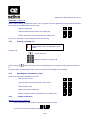
4.2.3
Access command
The access command sequence is the following:
#
Τ
#
#
Τ
#
When entering the command, keep pauses between digits to less than one second
4.2.4
Structure of Commands
Each command specifies a "parameter index". Some parameters can be read and modified. Some other
can be read, but not modified.
The following commands are used:
– modify commands, used for parameter configuration
– read commands, used to read the current value of a configuration parameter
– reset commands are used to restore configuration values to the factory default
Modify commands have the following structure:
Τ
<parameter index>
Τ
Read and reset commands have the following structure
11/59
<parameter value>
#
Aethra NT-IP User's Manual sw rev. 2.0
Τ
4.2.5
<index>
#
Entering commands
When the NT-IP enters the configuration mode the device emits an audible tone. When the initial * key is
operated, the NT-IP stops the generation of the tone and prompts the user with the message:
"enter the parameter index":
The user enters a two digit code representing the parameter index and: terminated by the * key for modify
commands, or the # key for a read command. Only the last two digits entered are considered, so in case
of an error the user simply re-enters the correct digits and then press * or #.
If the entered index is not valid, a:
"wrong entry"
message is generated, followed by the audible tone indicating the ready state.
If the entered index is a valid one, then the user is prompted with a message:
"enter the parameter value".
4.2.5.1
Modify commands
The new value can now be entered, followed by the # key. Valid operations are confirmed via the
message:
"the parameter value <x> is <y>"
where <x> and <y> represent the address and the assigned value.
If the assigned value is incorrect, the following message is given:
"wrong entry"
The configuration mode can be interrupted at any time by going on-hook.
4.2.5.2
Read Commands
The current value of the requested parameter is indicated via the message:
"the parameter value <x> is <y>"
12/59
Aethra NT-IP User's Manual sw rev. 2.0
4.3
Description of configuration parameters
The NT-IP has a number of user programmable configuration parameters, contained in a non volatile
memory.
Some parameters (such as operating mode, access configuration, remote configuration numbers, etc.)
refer to the system as a whole.
Other parameters (such as:
– assignment of network numbers, port profile, activation of call waiting
– generation of metering impulses
– delayed clear back
– level setting, etc.
are specified for each a/b port:
4.3.1
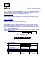
General configuration parameters
PARAMETER
ACC
INDEX
TEI assignment
O
02
Voice announcements
O
03
Operating modes
O
04
Incoming call management
U
05
Amount of currency per charging unit
O
08
Enable local configuration1
O
30
Remote configuration numbers
O
70…89
Remote configuration subaddress
O
90
VALUES
DEFAULT
point-to-point (fixed TEI)
00....63
multi-point (dynamic TEI)
64
no
0
yes
1
S bus enabled
0
S bus disabled
1
broadcast
0
alternate
1
a/b port 1 preferred
2
a/b port 2 preferred
3
amount
4 digits
multiplier
1 digit
enabled
0
disabled
1
multi-point
No
enabled
broadcast
0…28 digits
0..4 digits
none
enabled
Empty
9999
Table A - General parameters
Note: "U" = user access, "O" operator only access
4.3.1.1
TEI assignment
If the access has a multipoint configuration, the NT-IP must be configured for "automatic TEI
assignment", by assigning the value 64 in the TEI assignment parameter (index 02).
If the access has a point-to-point configuration, the TEI must be programmed with a value ranging from
00 to 63, according to the value of the TEI assigned by the ISDN service provider (usually the value 0 is
used).
Τ 0 2 Τ 0 0 # for a point-to-point access with TEI 0
Τ 0 2 Τ 6 4 # for a multi-point access
1 this command is only active in remote configuration mode
13/59
Aethra NT-IP User's Manual sw rev. 2.0
4.3.1.2
Voice messages
The NT-IP may be programmed to generate voice announcements to provide the user with the results of
operations involving some supplementary (e.g. when in band announcements are not provided by the
network) or local services.
Τ 0 3 Τ 0 # To activate the voice messages
Τ 0 3 Τ 1 # To deactivate the voice messages
NOTE: Voice announcements generated to guide the user during the configuration procedures cannot be
deactivated.
NOTE: For some localisation this parameter is disabled and cannot be modified
4.3.1.3
Operating mode
The NT-IP can be used as described above or simply as a pair gain (line doubler) by deactivating the S
bus. The relevant configuration procedure is described in below:
Τ 0 4 Τ 0 # full NT-IP configuration; S bus enabled
Τ 0 4 Τ 1 # line doubler configuration; S bus disabled
4.3.1.4
Incoming call management
When an incoming call is compatible with both a/b ports (i.e. matching MSN and port profile), four
different options can be specified
mode
operation
value
broadcast
simultaneously offered to both a/b
0
alternate
alternatively offered to either a/b 1 or a/b 2
1
a/b 1 preferred
preferentially offered to a/b1
2
a/b 2 preferred
preferentially offered to a/b1
3
Of course, if either a/b port is not free and not CW-enabled, the call will be offered to the other port
independently of the setting of this parameter.
As an example to program the broadcast mode, use:
* 0 5 * 0 #
4.3.1.5
Amount of currency per charging unit
This parameter representes the amount of currency for a charging unit. It contains four significant digits
and an additional digit to indicate the number of digits after the decimal point.
For example, to program a value of 6.05 units of local currency for a single pulse, either use:
* 0 8 * 6 0 5 0 3 #
or
* 0 8 * 0 6 0 5 2 #
4.3.1.6
Enable local configuration
This parameter can be used to disable local configuration. The command
14/59
Aethra NT-IP User's Manual sw rev. 2.0
* 3 0 * 1 #
disables any locally initiated configuration procedure.
4.3.1.7
Remote configuration numbers and subaddress
Remote configuration numbers and subaddress are used to recognize remote configuration calls (see
§4.2.2). Up to 20 remote configuration numbers and one subaddress can be programmed into the NT-IP.
These number should only be assigned during the installation.
As an example, to assign the second remote configuration numbers to 21345:
* 7 2 * 2 1 3 4 5 #
To program the subaddress to 9876:
* 9 0 * 9 8 7 6 #
4.3.2
a/b port Specific Parameters
Separate commands are used for each a/b port: N = 1 holds for the 1st a/b port, N = 2 for the 2nd a/b port.
The value of some port specific parameters contain a sequence of digits. Each digit holds the value of a
specific sub-parameter.
When entering a new value, use 9 to skip a digit position without altering the current value of the subparameter.
It is not necessary to update all digit positions in the dialling mode and a/b port service parameters: e.g. if
only digit position 1 and 2 have to be modified, then press # after entering the two digits to terminate the
command.
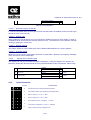
ACCESS
INDEX
1° network number
PARAMETER
U
N1
0....28 digits
VALUE
Empty
2° network number
U
N2
0....28 digits
Empty
3° network number
U
N3
0....28 digits
Empty
Port Status
U
N6
See Table C - Port Status
POTS register 1
U
N7
See Table D - POTS register 1
POTS register 2
U
N9
See Table E - POTS register 2
Fixed destination call
U
3N
See Table F - POTS register 3 (FDC)
POTS register 3
U
4N
See Table G - POTS register 4
Special Service Enables
O
5N
See Table H - Special Service Enables
Delayed Clear back duration
O
6N
value of delayed clear back duration (1…120)
Table B - Port specific registers
4.3.2.1
Port Status (N6)
POSITION
1
value
port status
0
IDLE
1
error-status
2
outgoing call
3
active call
4
off-hook
5
ringing
Table C - Port Status
15/59
DEFAULT
60
Aethra NT-IP User's Manual sw rev. 2.0
4.3.2.2
POTS register 1 (N7)
POSITION
SUB-PARAMETER
1
Tone dialing
2
Recall/flash key
VALUES
DEFAULT
pulse and tone
0
tone only
1
enabled
0
disabled
1
pulse and
tone
enabled
Table D - POTS register 1
4.3.2.3
POTS register 2 (N9)
POS
1
SUB-PARAMETER
port profile
VALUE
DEFAULT
deactivated
0
speech/audio
1
telephone
2
fax
3
deactivated
0
activated
1
deactivated
0
activated
1
high level
0
low level
1
disabled
0
enabled
1
2
reserved
3
generation of metering pulses
4
delayed clear back
5
audio level
6
polarity inversion
7
presentation of CLI on
waiting calls (off-hook)
disabled
0
enabled
1
8
presentation of CLI on
incoming calls (on-hook)
disabled
0
enabled
1
9
voice or tone to confirm CF and CW
services
tones
0
announcements
1
speech/audio
deactivated
deactivated
high level
disabled
disabled
disabled
tones
Table E - POTS register 2
4.3.2.3.1
Port Profile
Each a/b port can be set according to the type of analog terminals connected2. The following settings are
possible:
speech/audio
if different types of terminals (e.g.: a phone and a modem) are connected to the same port
telephone
if only telephones are connected to the port
fax
if only a fax machine is connected to the port.
deactivated
when the port is "deactivated", incoming calls are not offered to this port, so that the network and the calling user will
be informed that no phone is ringing. This mode may be used when no terminal is connected to the port. Outgoing
calls are however possible.
2
this setting uses certain signalling features of the ISDN. For example, calls coming from an ISDN phone
(or another NT-IP POTS ports set as "telephone") will not be answered by a POTS port confired with a
"fax" profile.
16/59
Aethra NT-IP User's Manual sw rev. 2.0
4.3.2.3.2
Audio level selection
The NT-IP provides for two sets of reference audio levels for each a/b port. Higher levels meet reference
levels values specified by most network providers and are suited for modems and fax devices. Lower
levels provide for greater echo attenuation and better acoustic comfort.
4.3.2.3.3
Polarity reversal
When this feature is enabled, the voltage applied to the a/b interface is reversed when the called party
answers the call (reception of the connect message). The voltage then reverts to the normal polarity when
the calling user goes on-hook.
4.3.2.3.4
CLI presentation
Two separate parameters are used to respectively enable the CLI presentation on normal calls (on-hook
transmission) and the CLI on waiting calls (off-hook transmission).
4.3.2.3.5
Voice or tone to confirm CF services
This parameter allows the user to choose between audible tones or voice announcements to confirm
activation and deactivation of Call Forwarding services. Audible tones may be required when using
special phone sets that decode the confirmation or rejection tones, usually provided on POTS networks
when requesting CF activation or deactivation.
4.3.2.4
POTS register 3 (FDC) (3N)
This register holds the timed delay and the target number for the fixed destination calls (FDC). Separate
values are stored for either port.
1
2…29
call delay
target FDC address
FDC disabled
delay (value+1)
called number
00
01…30
1…28
disabled
empty
Table F - POTS register 3 (FDC)
As an example, use
* 3 2 * 9 5 5 5 3 3 3 3 #
to program a/b port 2 to generate a FDC to the number 555-3333, ten seconds after going off-hook.
The destination number can be modified by a keypad procedure outside configuration. Any modification
will be reflected in this parameter.
4.3.2.5
POTS register 4 (4N)
1
Reminder ringing of held call
2
Reserved
3
3
4
5
6
Activation of Waiting call
st
ringing pattern associated to 1 MSN
nd
ringing pattern associated to 2 MSN
rd
ringing pattern associated to 3 MSN
7
CLIR service
8
COLR service
deactivated
activated
0
1
disabled
enabled
ringing pattern ID (0 to 5)
ringing pattern ID (0 to 5)
ringing pattern ID (0 to 5)
no presentation id
presentation restricted
presentation allowed
no presentation id
0
1
0
0
0
0
1
2
0
17/59
deactivated
pattern 0
pattern 0
pattern 0
no presentation ID
no presentation ID
Aethra NT-IP User's Manual sw rev. 2.0
presentation restricted
presentation allowed
1
2
Table G - POTS register 4
4.3.2.5.1
Reminder ringing of held call
If a call on hold exists when the user goes on-hook and this feature is enabled, the a/b port will ring to
remind the user of the held call.
4.3.2.5.2
Waiting calls
When enabled by this parameter, the user receives an audible tone when a call is waiting, or when a
compatible call is received but the relevant a/b port is busy. This allows the user to take the call after
clearing or holding the current call.
4.3.2.5.3
Ringing patterns
This feature allows the user to distinguish calls to different MSN based on the ringing patterns.
4.3.2.5.4
CLIR and COLR
Allows the user to include "presentation restricted" or presentation “allowed” in all outgoing messages
(resp. set-up and connect messages).
4.3.2.6
Special Service Enables (5N)
This register can only be accessed via remote configuration. Using this register, the operator can
selectively enable the relevant special services (Fixed Destination Calls, Call Capture, Alarm Calls)
1
Fixed Destination Calls
2
Call Pick-up
3
Wake-up calls
disabled
enabled
disabled
enabled
disabled
enabled
0
1
0
1
0
1
Table H - Special Service Enables
4.3.3
Read Commands
ACCESS
announcement
Τ 0 0 #
U
manufacturer name, hardware and software revision
Τ 0 9 #
U
read activation status of port specific and global parameters
Τ 1 6 #
U
status of a/b port 1: 0 = OK, 1 = NOK
Τ 2 6 #
U
status of a/b port 2: 0 = OK, 1 = NOK
Τ 5 0 #
U
current power status: 0 = emergency, 1 = normal
Τ 6 0 #
U
current S bus configuration: 0 = short, 1 = extended
Τ 9 1 #
O
calling number of the last configuration call
18/59
enabled
enabled
enabled
Aethra NT-IP User's Manual sw rev. 2.0
Τ 9 2 #
U
date and time
Τ 9 8 #
U
reset all user configuration parameters to their default values.
Τ 9 9 #
O
reset all user and operator configuration parameters to their default values
Table I - Direct Commands
4.3.3.1
Read activation status of port specific and global parameters (command 09)
This command is used to check if some parameters have been changed via a remote configuration call,
but are still waiting to be activated. Four digits are read back, according to the following table:
4.3.3.2
Pos
refers to
1
a/b1 specific parameters
2
a/b2 specific parameters
3
global parameters
4
data port parameters
Value
1
0
1
0
1
0
1
0
Meaning
waiting for activation
activated
waiting for activation
activated
waiting for activation
activated
waiting for activation
activated
Read date and time
This command allows to read date and time as maintained by the NT-IP.
The NT-IP uses date and time information contained in some messages from the network to update its
internal clock. After reset, no such information is maintained until the internal clock is synchronized to
date and time provided by the network.
4.3.3.3
Default reset commands
These commands are used to reset all configuration parameters to the factory default values.
NOTE: remote configuration numbers are not affected by these commands.
4.3.4
Examples of configuration procedures
4.3.4.1
Programming a/b port registers
To deactivate a/b port 2 if not connected to any terminal (phone or modem):
* 2 9 * 0 9 9 9 9 #
or
* 2 9 * 0 #
To configure a/b port 1 as "speech/audio":
* 1 9 * 1 9 9 9 9 #
or
* 1 9 * 1 #
To configure a/b port 2 as "telephone" (i.e. only a phone is connected to the a/b port):
19/59
Aethra NT-IP User's Manual sw rev. 2.0
* 2 9 * 2 9 9 9 9 #
or
* 2 9 * 2 #
4.3.4.1.1
Metering pulses
To activate the pulse generation for a/b port 1:
* 1 9 * 9 9 1 9 9 #
or
* 1 9 * 9 9 1 #
To deactivate the pulse generation for a/b port 2:
* 2 9 * 9 9 0 9 9 #
or
* 2 9 * 9 9 0 #
4.3.4.1.2
Delayed clear back
To activate the clear-back feature for a/b port 2:
* 2 9 * 9 9 9 1 9 #
or
* 2 9 * 9 9 9 1 #
4.3.4.1.3
Audio levels
To program a/b port 1 for high audio levels (recommended option when modems are used):
* 1 9 * 9 9 9 9 0 #
To program a/b port 1 with low audio levels:
* 1 9 * 9 9 9 9 1 #
4.3.4.1.4
An example of complete programming
The command
* 2 9 * 2 2 1 1 1 #
will program a/b port 2 as follows:
type of terminal
call waiting
delayed clear-back
telephone
type I and type II CW enabled
enabled
20/59
Aethra NT-IP User's Manual sw rev. 2.0
generation of metering pulses
audio levels
enabled
low
21/59
Aethra NT-IP User's Manual sw rev. 2.0
5
SUPPLEMENTARY SERVICES
Two types of services are supported by the NT-IP:
–
–
5.1
ISDN supplementary services, i.e. services that rely on network features
Local additional services, that do not imply interactions with the network
ISDN supplementary services
Most ISDN supplementary services are related to the deployment of advanced telephony services (e.g.
call waiting, call forwarding, calling line indication, etc.) and, from the user's perspective, bear a close
resemblance to the corresponding services provided by the analog networks.
NOTE: Most supplementary services may not be available on a general basis and may require a
specific agreement with the ISDN service provider.
The NT-IP supports a number of such ISDN supplementary services:
number identification services
MSN
• multiple subscriber number
CLIP
• calling line identification presentation
CLIR
• calling line identification restriction
COLP
• connected number presentation
COLR
• connected number restriction
MCID
• malicious Call Identification
call offering services
TP
• terminal portability
CFU
• call forwarding unconditional
CFB
• call forwarding on busy subscriber
CFNR
• call forwarding on no reply
ECT
• explicit call transfer
call completion services
HOLD
• call hold
CW
• call waiting
multiparty services
3PTY
• three party conference
community of interest services
CUG
• closed user group
charging services
AOC
• advice of charge
5.2
User procedures
The use of some supplementary services, such as MSN, CLIP and COLP do not require any user
procedure. They are made available on a general basis or by arrangement with the service provider, and
no action is required to activate, deactivate or invoke the service.
Some services (e.g. call forwarding procedures) must be explicitly activated and deactivated by the user
and then they are automatically operated when needed (e.g. when an incoming call meets the conditions
for being forwarded). These services also usually support a status interrogation procedure.
Other services (e.g. 3 party conference, MCID) require instead an explicit invocation by the user to
operate.
To operate these procedures when using NT-IP, the user usually presses a sequence of keys starting with
* or # on the phone keypad, and in some cases precedes this sequence by the action of the register recall
(RR) or hook flash (HF) key. These procedures usually mimic those used in POTS networks for the
equivalent services.
22/59
Aethra NT-IP User's Manual sw rev. 2.0
The NT-IP therefore provides for the necessary "mapping" between such POTS-like procedures and the
signalling procedures used on the network side. These latter procedures conform to the relevant ETSI
standards3, that describes signalling that takes place between the central office and the user terminal on
the D-channel.
The NT-IP also supports the Keypad Protocol. This protocol is much simpler and it basically results in the
keys pressed being transparently transmitted as "keypad information" to the switch, where all the
processing takes place. The keypad protocol requires less processing on the part of the user's terminal,
which basically has no knowledge of what service is being requested by the user. Older switch
implementation tend to offer most services using the "keypad" protocol, although newer switch releases
now offer supplementary services using the feature-rich "functional" protocols4.
NT-IP makes it completely transparent to the user what kind of protocol has to be used to obtain a specific
supplementary service. The user only presses the same "key sequence" required when connected to the
POTS.
5.3
Service description and user procedures
The following sections provide a short description of each supplementary service supported by the NT-IP
for the a/b ports and then details user procedures to configure or operate the service.
Information on the outcome of activation, deactivation, interrogation and invocation procedures are
provided by a voice announcement or, for the Call Forwarding services and the Call waiting service, such
announcements can be replaced by audible tones, according to the setting of the position 9 of parameter
N9).
When tones are used, a positive outcome is signalled trough a dial tone while a negative outcome is
signalled using a busy or a congestion tone.
5.3.1
Multiple Subscriber Numbers (MSN)
This service allows for multiple telephone numbers (MSN's or directory numbers DNs) to be assigned to an
ISDN access. This basically permits the user to allocate numbers to different terminals and/or services.
The maximum number of MSN's per access is a network option.
5.3.1.1
User procedures
In the NT-IP, either a/b port can be allocated one, two or three MSN's, while the RS-232 port can only be
assigned one MSN. When MSN’s are allocated, the NT-IP routes incoming calls5 to the relevant port(s),
based on the called party number information contained in the incoming call set-up message. If no MSN
are programmed for a port, then incoming calls are offered to that port independently of the called party
number included in the incoming call set-up message.
The first MSN assigned to the a/b port is included as the "calling party number" in outgoing calls.
MSN numbers are separately programmed for either port in registers N1, N2 and N3.
It may be sufficient to program any number of digits as required to identify the number among those
assigned to the access, but, as a general rule, it is safer to enter the whole MSN as some networks may
not properly process such abbreviated MSNs.
3 ETS 300 196-1 and other services specific ETS
4 Depending on the switch implementation, a service (e.g. call forwarding) can be supported either by a "functional" or the "keypad"
protocol. Furthermore, when using the "functional" protocol, some variants may exist among different switch technologies or in option
offering policies by the operator. These differences have an impact on the NT-IP, and some country specific "fine-tuning" may be
necessary for proper operation.
5 additional checks are performed to assure that the call is compatible with the port profile (speech, audio, fax)
23/59
Aethra NT-IP User's Manual sw rev. 2.0
5.3.2
Calling Line Identification Presentation (CLIP)
This service allows the called subscriber to receive information regarding the identity (telephone number
and possibly subaddress) of the calling party. The calling user may either provide the calling number (in
this case the number is screened, verified and formatted by the network), or the network itself uses the
default accesses number. No checks are performed instead on the user-provided subaddress, which is
transparently passed to the called user.
The service is activated or deactivated by the network operator and therefore no user procedures related
to the service deployment.
5.3.2.1
User procedures
At the calling site, the NT-IP includes in the outgoing call set-up message the first programmed MSN
associated with the port that originated the call. If the first MSN is not programmed, then no information is
included.
5.3.3
Restriction of caller's ID (CLIR)
This service allows the calling user to request that her/his party’s number (and subaddress) is not
presented to the called party. There are different subscription options for CLIR:
option
on a per-call basis
(default allowed)
on a per-call basis
(default restricted)
permanent basis
5.3.3.1
operation
the calling party identity is presented unless the user explicitly requests restriction
the calling party identity is restricted unless the user explicitly requests to allow its presentation
the calling party identity is restricted independently of the user requesting the contrary
User procedures
Depending on the value assumed by the CLIR parameter (register 4N, position 7), the outgoing SETUP
message contains a “presentation indicator” set as shown in the following table:
value of CLIR param
0 (default)
1
2
no prefix
no indication
restricted
allowed
*31#
restricted
restricted
restricted
#31#
allowed
allowed
allowed
If the CLIR parameter is set to 0 and the CLIR service is available at the user’s access, the user can
restrict the presentation of the own number by dialling *31# in front of the called number.
Alternatively, the user can set the CLIR parameter to 1 to restrict presentation for all calls, unless #31# is
dialled in front of the called number for a specific call.
Setting the CLIR parameter to 2 allows for a “presentation indicator” to be included by default in the
SETUP message6. The user has however the possibility to request restriction, by prefixing *31# to the
called number.
5.3.4
Connected Line Identification Presentation (COLP)
This service allows the calling subscriber to receive information regarding the identity (telephone number
and possibly subaddress) of the party answering the call (due to possible call diversions, this number may
be different from the called one).
6 as required by some networks
24/59
Aethra NT-IP User's Manual sw rev. 2.0
5.3.4.1
User procedures
The NT-IP uses the first MSN for the relevant port and it includes this information (if present) in the
CONNECT message. This service is only supported in the outgoing direction only: display of the
connected party number is not available on a/b ports.
5.3.5
Connected Line Identification Restriction (COLR)
This service allows the answering user to request that the number (and subaddress) be not presented to
the calling party.
5.3.5.1
User procedures
Each a/b port can be programmed to request COLR on each call by setting register 4N, position 8 to 1.
(See §4.3.2.5). No activation procedure is available, so the COLR is only provided for all calls.
5.3.6
Malicious caller ID (MCID)
Upon invocation of this service during an incoming call, the network registers and stores under control of
the network operator critical information regarding the call, such as calling and called party number, time
and date of the call. A subscription option allows for automatic registering of all unanswered calls.
The MCID supplementary service is available by arrangement with the service provider. Cancellation is at
the request of the subscriber or for service provider reasons.
5.3.6.1
User procedures
The NT-IP allows the user to invoke the MCID service by pressing R 9 during the active phase of the call
or immediately after the caller has disconnected.
5.3.7
Terminal Portability
This service allows a user to suspend a call and subsequently to resume it at the same terminal and at the
same socket, or after moving the terminal to a different socket, or at a different terminal on a different
socket.
When the call is suspended, the network maintains the connection to the remote user and it stores
relevant information for the call (B channel), to allow the call to be re-established at a later time.
When suspending a call, the user may specify a "call identity", which has to be indicated when the call is
being resumed.
5.3.7.1
User procedures
The TP service is used in the NT-IP to "transfer" active calls from one a/b port to the other. When a call is
active on one port (say, port 1), the user suspends the call by pressing:
R*79#
if no call ID is entered, or
R*79*1234#
if a call ID (e.g. "1234") is desired. The user then goes on-hook.
To resume the call at the other port, the user goes off-hook and dials
*79#
or, if a call ID has been associated with the call:
*79*1234#
25/59
Aethra NT-IP User's Manual sw rev. 2.0
Note that the suspended call can also be resumed from the same port or from a terminal connected to the
S bus.
5.3.8
Call Waiting (CW)
This service allows the user to be notified of an incoming call, even when both channels on the user's
access are busy, and therefore no channel is available for the call. Were the CW service not available at
that access, then the call would be cleared with cause "user busy". Standard calls are offered with
indications of the associated channel, while call set-up messages for waiting calls bear the indication "no
channel available".
Upon receiving this notification, the user can take appropriate actions to make one channel available (such
as clearing or placing one of the existing calls on hold) and then answer the call.
The maximum number of waiting calls is a network option. The CW supplementary service is available by
prior arrangement with the network operator.
5.3.8.1
User procedures
The NT-IP uses audible tones (CW tones) to inform the busy user of a "waiting call". As an extension to
the standard service, the NT-IP also generates CW tones in the case that a "standard" (i.e. non waiting
call is being offered) but the compatible port is busy.
The user can dynamically activate or deactivate the service by going off-hook and then pressing
*43#
to activate the service, or
#43#
to deactivate the service.
Activation and deactivation of the CW service result in setting the position 3 of parameter 4N respectively
to 1 or 0.
To interrogate the service the user presses
*#43#
to receive a voice announcement (or a tone) on the service status.
!
disabling CW tones may be necessary to
avoid interference with operation of modem
or fax devices.
When CW tones are heard during a call, the user can ignore the call or (depending on the services
provided by the network and subscribed to by the user):
R0
R 1
R 2
If the user goes on-hook when a waiting call is present, the a/b port will ring (provided that the conditions
for delayed clear back are not met).
clear the waiting call
clear the active call and answer the waiting call
put the active call on hold and answer the waiting call
5.3.9
Call Hold and Retrieve (HOLD)
This service enables a user to place an existing call into a stand-by state and, subsequently, to retrieve the
call. When the call is the held state, the associated channel becomes available for use with other calls by
the same user (e.g. to start a new call or to accept a waiting call).
The HOLD service may available on a subscription basis or on a general basis.
26/59
Aethra NT-IP User's Manual sw rev. 2.0
The HOLD service is commonly used to start a new call or to accept a waiting call without releasing the
currently active one. When one call is active and another one is held, the user can then switch between
calls or activate other supplementary services such as Three Party or Explicit Call Transfer.
5.3.9.1
User procedures
With NT-IP, the user can place an active call on hold by and then start a new call by pressing the R key,
waiting for the dial tone and then dialling the new number.
Once the second call is established, the user can:
clear the call on hold
clear the active call and resume the call on hold
switch between calls
starts a three party conference
request the explicit call transfer
R0
R1
R2
R3
R4
When the user goes on-hook and a call is still on hold, a programmable feature of the NT-IP allows the
user to be notified of the call still on hold. ("reminder notification of held call" register 4N, position 1,
see §4.3.2.5).
If this feature is enabled, the POTS will start ringing when the user goes on-hook and it keeps ringing for
60 seconds. If the user goes off-hook during this time, the held call is automatically retrieved and the
conversation to the held party is re-established. When this time expires, the held call is disconnected.
If the feature is disabled, when the user goes on-hook both the active and the held call are immediately
disconnected.
5.3.10
3-Party Conference (3-Pty)
This service enables the user with two ongoing calls (one active and one in the held state) to bridge the
two calls into a three-way conference, so that a three-way conversation is possible among the promoting
user and the two remote parties.
The promoting user has complete control over the conference, as he/she can disconnect or temporarily
exclude either remote party from the conference, or terminate the conference.
5.3.10.1
User procedures
The 3-party conference can be entered when one active call (A) and one held call (H) exist. The user
presses
R3
to join call H into the conference.
Subsequently the user can:
release the connection added on conference (H)
resume private conversation with A (H returns to the held state)
request explicit call transfer
release the connection to A and retrieve the connection to H to the active state
resume private conversation with H (place A on hold, retrieve H to the active state)
5.3.11
R
R
R
R
R
1
2
4
5
6
Closed User Group
This service allows a user to be a member of one or more closed user groups. When such a membership
is established, the network performs special access checks over calls originated or received by the user.
Members of the same CUG are usually allowed to communicate among themselves, but calls leaving or
entering the group are usually restricted. Nevertheless, as subscription options, a CUG member can be
27/59
Aethra NT-IP User's Manual sw rev. 2.0
granted the right to place (Outgoing Access) and/or to receive (Incoming Access) calls outside the CUG
(non-CUG calls). Some additional restrictions can be placed on CUG members to prevent them from
placing (outgoing calls barred) or receiving calls (incoming calls barred) within the CUG.
The CUG service is available on a prior arrangement with the network provider.
As a subscription option, the user can subscribe to a preferential closed user group. In this case, outgoing
calls are by default treated as CUG calls, and no action is required on the part of the user's terminals to
place CUG calls.
If no preferential closed group has been subscribed to, then the user must explicitly indicate a CUG index
when placing a CUG call.
5.3.11.1
User procedures
In the NT-IP, a user with a preferential CUG places a call outside the CUG7 by dialling
*01#
in front of the called number. Calls within the CUG do not require any prefix.
Users without preferential CUG need to explicitly indicate a CUG index (in the example, 1 2 3 4) to place
CUG calls by dialling:
*01*1234#
in front of the called number. Non-CUG calls do not require any prefix.
5.3.12
Advice of Charge (AOC)
This service allows the served user to receive charging information related to calls and to the invocation or
activation of supplementary services.
The AOC supplementary service is usually activated on a general basis, i.e. the served user receives
charging information at every call. On some networks, activation of the service may be required on a percall basis. The AOC service actually consists of three services:
the AOC-S provides information on charging rates at call set-up time and when charging rates change
during a call
– the AOC-D service provides cumulative charging information during the active cycle of a call.
– the AOC-E service provides recorded charging information at the end of a call.
A network operator may choose to provide charging information either in "charging units" or in as a
currency amount.
–
5.3.12.1
User procedures
The NT-IP is able to process the received charging information and to generate "charging pulses" on the
a/b port that originated the call. Generation of charging pulses is enabled for either port by setting the
relevant configuration parameter (registers N9, position 2) to 1.
Additionally, when charging information is provided as currency amount, the general configuration
parameter 08 contains the amount of currency equivalent to a charging pulse. This register contains 4
significant digits and an additional multiplier digit that specifies the number of digits after the decimal
point. For example, if 6.05 units of local currency correspond to a charging pulse, the register shall be
programmed either with "60503" or "06052".
7 the user must have subscribed to the Outgoing Access (OA) option
28/59
Aethra NT-IP User's Manual sw rev. 2.0
!
5.3.13
charging pulses may adversely affect
operation of modem or fax devices.
Explicit Call Transfer (ECT)
This service enables the user with two ongoing calls (one active call to A and one held call to B) to request
the network to join user A and user B in a single call. If the request is successful, the requesting user is
then disconnected while user A and user B remain connected.
5.3.13.1
User procedures
In the NT-IP, the ECT is requested by pressing R 4 when a call is active and another call is on hold (this
also includes when the 3-PTY service is active).
5.3.14
Call Forwarding Services (CF)
These services are used to instruct the network to divert incoming calls to a different number. Three
different types of service are provided:
– call forwarding unconditional (CFU) : all call are diverted
– call forwarding busy (CFB): calls are diverted if they meet busy
– call forwarding no reply (CFNR): calls are diverted if no reply is obtained from the called user
If the user's access has the MSN service, then the services can be activated on a "served number" basis
or for "whole access" (i.e. independently of the called number). This feature may not be available on a
general basis: i.e. it may require a specific subscription by the served user, or it may not be offered by the
network provider.
Additionally, separate requests can be issued for different bearer services (e.g. audio, speech, and data).
This feature may not be available on a general basis. In any case, the user can submit a request for
diverting calls for "all services".
As each activation can specify a different "diverted-to" number, the user has the possibility to specify
different target numbers for each different service and for each different number on the access.
The CF supplementary services are offered on a subscription basis, with several notification options:
–
to the served user
– notification of forwarding
– notification of service being active8
– to the calling user
– notification of forwarding
– to the “forwarded-to user”
– presentation of the "served user" number when the diverted call is offered
Activation, deactivation and interrogation procedures are available.
5.3.14.1
User procedures
The NT-IP provides full support for the CF services using the ETS functional protocol specified in ETS 300
207-1. As a customer localisation option, the NT-IP also provides for support to the CF services using the
stimulus procedures. The following description applies to the “functional” procedure.
8 this notification occurs when the served user places an outgoing call
29/59
Aethra NT-IP User's Manual sw rev. 2.0
When wishing to request unconditional transfer of incoming calls to a defined number, the user goes offhook and dials
Τ 2 1 Τ <diverted-to-number> #
This sequence translates into a request to the network to activate the CFU service for the "served number"
that is represented by the first MSN assigned to the port.
The activation, deactivation and interrogation requests can also explicitly contain a served user number:
e.g.
Τ 2 1 Τ 8 7 6 5 4 3 2 Τ 2 3 4 5 6 7 8 #,
requires activation of CF from number 8765432 to the number 2345678. The same holds for deactivation
(# 2 1 Τ 8 7 6 5 4 3 2 #) or interrogation (Τ
Τ 2 1 Τ 8 7 6 5 4 3 2 #).
If the first MSN is not assigned and no served user number is included in the request, then the "all
number" version of the request is used9. In all cases, the request is issued for "all services".
To deactivate the CFU service the user goes off-hook and dials # 2 1 #.
The user is informed on the outcome of the activation, deactivation or interrogation requests either by a
voice announcement or a tone by setting position 9 on register N9 to 0 or 1. (see §4.3.2.3).
The user can also interrogate the network on the activation status of the CFU by going off-hook and
dialling
Τ#21#
A voice announcement or a tone informs the user about the status of the service. If the voice
announcement are used, the user is also informed about the served user number and the diverted-to
number10.
Procedures for CFB and CFNR services are similar to the ones described for the CFU, except for the
"service code" 21, changing to 61 for the CFNR and to 67 for the CFB.
5.4
Additional services
The following services do not strictly rely on network provided supplementary services, but they are
instead implemented locally and do not cause transactions with the network.
5.4.1
Call line identification (CLI) services
This service, also known as "CLASS" services, allows a user to be informed of the number of the calling
party before answering a call. To this purpose, a specific display device must be connected to the a/b port
or, alternatively, the display may be integrated in the phone.
5.4.1.1
User procedures
CLI services are provided for normal and waiting calls. They are available for both ports in normal and in
restricted power mode and in every situation: e.g. simultaneous occurrence of call offering to both a/b, or
when the other a/b port is already ringing, etc.
9 if the "per served user number" service is not available, the network will however process the request as if contained "all number".
10 the activation, deactivation and interrogation requests may come out to be invalid in the case that the following conditions occur:
1.
2.
3.
the network option "activation, deactivation and interrogation for all numbers" has the value "NO",
the MSN service is provided to the access,
the "all number" version of the request is used, due to the first MSN not being programmed.
In this case the first MSN must be programmed to allow proper service operation.
30/59
Aethra NT-IP User's Manual sw rev. 2.0
The NT-IP provides the calling party number or an indication that the number is not aviailable (“O”) or
restricted (“P”).
Date and time are also included if this information is received form the network in the specific information
element contained in a CONNECT or in other messages.
The NT1+ uses this information to update an internal clock. After reset, the content of the internal clock is
invalidated and are therefore not used. When a message is received including this information, the
internal clock is updated to the value indicated by the network and is then kept running.
When this date and time information is not available, a dummy string of question marks is substituted for
the date and time in the CLI message.
These services can be selectively enabled by setting parameter 8 (CLI on standard calls) or parameter 7
(CLI on waiting calls) in configuration register N9.
5.4.2
Fixed Destination Call
This service allows a user to place a call to a selected number without any dialling. If the user goes offhook but does not dial any digit within a certain time, then the NT-IP automatically calls the selected
number.
5.4.2.1
User procedures
Configuration register 3N holds the required parameters for either port. The first two positions are set to 0
to disable the service. If not set to zero, these digit contains a value (1 to 30) which represents the
number of seconds for the timer. The following digits are used for the fixed destination number.
This service must be enabled using position 1 of register 5N. This register is reserved for the operator and
can therefore only be accessed via remote configuration.
The user can program the fixed destination number11 by going off-hook and dialling:
Τ53Τ4567890#
where 4567890 represents the new fixed destination number.
Interrogation of the actual value of this number is possible by dialling
Τ#53#
5.4.3
Alarm Calls
This service allows the user to schedule an alarm call at a certain time of the day. The alarm time must
be at least 10 minutes ahead of the current time. Up to three alarm calls per port can be scheduled, with a
minimum difference of 5 minutes between calls.
When the scheduled time for an alarm call is reached, then the NT-IP rings the a/b port. If the alarm call
is not answered or meets busy, the call is repeated once after 5 minutes.
When the alarm call is answered, a congestion tone is generated until the user goes on-hook.
5.4.3.1
User procedures
This service must be enabled using position 2 of register 51 (for port 1) and 52 (for port 2). This register is
reserved for the operator and can therefore only be accessed via remote configuration. To schedule an
alarm call, the user dials
Τ55Τhhmm#
11 the value of the FDC timer can only be modified in configuration mode.
31/59
Aethra NT-IP User's Manual sw rev. 2.0
where hh:mm represents the alarm time. The user receives a voice announcement for confirmation or
rejection. The request can be rejected if three alarms are already active, or if time constraints are not met.
The deactivate an alarm call the user dials:
#55Τhhmm#
to deactivate a specific alarm, or
#55#
to deactivate all alarms. The user receives a voice announcement for confirmation or rejection.
Interrogation of alarm status is accomplished using
Τ#55Τhhmm#
to interrogate a specific alarm, or
Τ#55#
to interrogate all active alarms. Alarm times are indicated for every alarm call.
5.4.4
Distinctive Ringing
This service allows the user to receive different ringing patterns for incoming calls based on the called
MSN contained in the call-set message.
5.4.4.1
User procedures
For either port, the user associates a specific ringing pattern to each of the three available MSN's.
To this purpose, positions 4, 5 and 6 of configuration register 4N allows for pattern selection. Patterns use
values 0 to 5:
value pattern
0
1.0 ON -3.0 OFF
1
0.4 ON - 0.2 OFF – 0.4 ON - 3.0 OFF
2
0.6 ON - 0.2 OFF – 0.2 ON - 3.0 OFF
3
0.2 ON - 0.2 OFF – 0.6 ON - 3.0 OFF
4
0.7 ON - 0.1 OFF – 0.2 OFF -3.0 OFF
5
0.2 ON - 0.1 OFF – 0.7 OFF -3.0 OFF
5.4.5
Delayed clear-back
This service allows a user with an incoming call active to go on-hook and to resume the call form another
phone connected to the same a/b port.
5.4.5.1
User procedures
When this feature is enabled by setting position 4 of register N9 to the value 1, the NT-IP postpones the
clearing of incoming calls for duration indicated in parameter 6N (default value is 60 sec), so that the user
is allowed to move the phone to another socket or to resume the call from another phone. Delayed clearback is automatically disabled when more than one call are associated at the a/b port (e.g. a call on hold).
5.4.6
Call Pick-up
This service allows a user to pick-up an incoming call ringing on the other a/b port.
32/59
Aethra NT-IP User's Manual sw rev. 2.0
5.4.6.1
User procedures
This service must be enabled using position 3 of register 51 (for port 1) and 52 (for port 2). This register is
reserved for the operator and can therefore only be accessed via remote configuration.
To capture the call when the other a/b port is ringing, the user goes off-hook and then dials:
Τ82#
33/59
Aethra NT-IP User's Manual sw rev. 2.0
6
6.1
OPERATING THE RS-232 PORT
Software installation for the MS™-Windows® 95 and Windows NT® 4.0
environments
!
It is recommended to install the driver before
connecting the NT-IP to your PC.
A diskette with modem driver files (.INF files) is provided with the unit.
To install the unit:
1) Insert the floppy disk with the driver file in the floppy drive A:
2) Double click on My Computer, Control Panel, and then Modem. If the Modem Properties window
appears, click on Add.
3) In the Install New Modem window, select option Don't detect my modem; I will select it from a list.
Click Next.
4) A window listing many modem types will be displayed. Click on Have Disk. Choose the appropriate
disk drive and click on OK.
5) When Windows 95 prompts you with a modem list, select the proper modem driver according to the
desired operation mode. Then click Next.
6) Choose the appropriate Communication port and click on Next.
The following drivers (.INF files) are available for the Windows 95 and Windows NT 4.0 environment:
–
single link PPP: this only allows for 64 kb/s single link PPP operation
multilink PPP: this allows for 128 kb/s PPP operation, and, depending on specific AT commands,
bandwidth-on-demand, call bumping and use of BAP/BACP
V.120
–
async to sync HDLC12
–
–
6.2
Hardware installation
1. Connect the a.c. adapter to the NT-IP and verify that the PWR LED on the NT-IP is ON
2. Connect the RS-232 port to the COM port of your PC, using a DB-9/DB-25 adapter cable (if needed)
To verify that the RS-232 is properly connected, use the Hyper-Terminal program supplied with Windows
95® may be used to exercise the NT-IP with AT-commands.
To ease installation, the NT-IP supports:
–
–
6.3
automatic recognition of the PC speed up to 230.4 kb/s during the command phase of the AT
command.
Plug&Play operation
Configuration Parameters
Except for A0 and A9 these commands can only be reached using the configuration program supplied by
Aethra. All S registers in the format *xx*zzzz…#
06
read port status (same as POTS)
A0
MSN
12 this mode is only used when the NT-IP is used to remote configure another NT-IP
34/59
Aethra NT-IP User's Manual sw rev. 2.0
A9
D0
D1
ED
6.4
Subaddress
buffer length
BOP
endpoint discriminator
AT commands
The NT-IP RS-232 port accepts AT commands in the format 8 bit, no parity, one or more stop bits.
AT command processing varies according to the current NT-IP status.
-
the command mode is entered after power-on or at at the end of a connection. Data from the PC are
interpreted as commands
-
the online mode is entered after an incoming or outgoing connection has been successfully
established. Any data received from the PC are used for transmission.
-
the online command mode is entered when an escape sequence (usually + + + with certain timing
constraints) is received in the online mode: subsequent data from the PC are processed as
commands, although the ongoing connection is still active
Some AT commands can only be accepted if no connection is established or in progress.
An AT string consists of the upper case AT or lower case at prefix followed by one or more commands
possibly separated by a space and terminated by terminating character (usually CR, hex 0D).
A reply is provided at every AT string. If all commands are correct a positive reply is sent (OKCRLF),
otherwise the first occurrence of an invalid or incompatible command a negative acknowledge is sent
(ERRORCRLF) and the rest of the string is ignored.
The special A\ or a\ commands can be used to repeat the last AT command.
Some internal registers are used to assign values to some parameters. These registers are identified by
the letter S followed by a number : e.g. the character used as a command terminator is contained in S3
(default CR), whilst S5 (default backspace BS) indicates an editing character, which is interpreted as a
command to cancel the last entered character in a command.
If the AT string contains more than one interrogation, a reply is provided for each request with a final OK or
ERROR.
6.4.1
Automatic Speed Detection
In the command and in the online command phase, the NT-IP automatically detects the PC speed, and
immediately upgrades its own speed to reflect the detected speed. Supported PC speeds are: 2400, 4800,
9600, 14400, 19200, 28800, 38400, 57600, 115200 and 230400 b/s.
The last speed detected before entering the online state is then used throughout the call.
6.4.2
AT command list
The description of every command is provided according to the following template:
Ex
F
Controls Local echo of received commands
P
x = 0/1 local echo disabled /enabled
V
command and online command mode
R
OK o ERROR if 'x' is out of range
This scheme indicates that:
–
the command “ATE1” or “ATE0” has the function (F) to control the local echo to the AT commands
received,
35/59
Aethra NT-IP User's Manual sw rev. 2.0
–
–
–
the command requires specification of one configuration parameter (P),
the command is valid (V) in the command or in the online command mode,
a positive (OK) o negative (ERROR) reply (R) is provided by the NT-IP.
36/59
Aethra NT-IP User's Manual sw rev. 2.0
6.4.3
Basic commands
A
F
Immediately answer the incoming call
P
None
V
When an incoming call exists
R
D
[P|T]
[nnnnn]
[/ssss]
Ex
H
Ix
O
Qx
Sn?
Sn=v
Vx
Xn
F
V
Start a new call to the indicated number/subaddress
P o T ignored, nnnn/ssss called number/subaddress (max.20/19 digits)
Also supports the ATDnnnn1[/ssss1]+nnnn2[/ssss2] format for dual numbers.
Command
R
new state of connection (CONNECT, NO CARRIER, ..), ERROR (incompatible)
F
Controls echo of received commands to the PC
P
x = 0/1 local echo disabled /enabled
P
V
Command and online command mode
R
OK o ERROR if 'x' is out of range
F
Release current call
P
None
V
Online
R
OK
F
V
Query device status
x = 0,2,4,5,7
Product code
"AETHRA – NT-IP"
x=1
ROM checksum
"XXXX" 4 hex digits
x=3
firmware version
"Vx.y"
x=6
report link status on the last call
Command or online command
R
See parameters
F
Switch back to online mode
P
None
P
V
online command
R
CONNECT o ERROR if send in an incompatible state
F
Display response codes
P
X = 0/1 display of response codes enabled /disabled
V
Command and online command modes
R
None if x = 1, if x = 0, either OK , ERROR if 'x' is out-of-range
F
Read Sn register
P
n = 0, 2, 3, 4, 5, 7, 18, 21, 23, 25, 27, 31, 32, 82, 83, 85, 87, 125, 126, 127
V
Command and online command modes
R
Current value of register Sn, ERROR if n invalid.
F
Assign the value v to register Sn
P
n = 0, 2, 3, 4, 5, 7, 18, 21, 23, 25, 27, 31, 32, 82, 83, 85, 87, 125, 126, 127
V
Command and online command modes
R
OK, ERROR if n invalid
F
Set verbose mode
P
x = 0/1 response in abbreviated/extended format
V
Command and online command modes
R
OK ifx = 1, 0 if x = 0, ERROR otherwise
F
Defines the format of the CONNECT message
P
n (0~7)
V
Command and online command modes
R
OK, ERROR if n out of range
37/59
Aethra NT-IP User's Manual sw rev. 2.0
Z
6.4.4
F
Reset all parameters to the values in the non-volatile memory
P
None
V
Command mode
R
OK, ERROR if status invalid
Extended "AT&" commands
&Cx
&Dx
&F
&Hx
&Sx
&W
&ZO=
<nnnn>
/
<ssss>
&ZO?
F
C109 management
P
x = 0/1 C109 always ON/connection status
V
Command mode
R
OK, ERROR if status incompatible
F
C108 Management
V
x=0
simulated C108 (always ON), C108/1, C108/2)
x=1
use as C108.1: start a call using stored number when C108.1 goes ON
x=2
use as C108.2: clear call when C108.2 goes off
Command mode
R
OK, ERROR if status incompatible.
F
Resets all parameters to default values
P
None or 0
P
V
Command mode
R
OK, ERROR if status incompatible.
F
flow control management
V
x = 0 flow control disabled
x = 3 hardware flow control (RTS/CTS), default
x = 4 software (XON-XOFF) flow control
Command mode
R
OK, ERROR if status incompatible
F
C107 management
P
x = 0/1 C107 always ON/ follows C108
P
V
Command mode
R
OK, ERROR if status incompatible
F
Save current settings in non-volatile memory
P
None
V
Command and online command mode
R
OK
F
Assign Directory number and subaddress
P
<nnnn>/<ssss> = assigned DN /subaddress (max. 28/19 digits)
V
Command mode
R
OK, ERROR if status incompatible
F
Readback the assigned DN /subaddress
P
none
V
Command and online command mode
R
nnnn/ssss
38/59
Aethra NT-IP User's Manual sw rev. 2.0
6.4.5
Enhanced AT commands
F
Bnn
P
V
R
Set the protocol in use for B-channel communication
20 = V.120
40 = PPP async to sync
command
OK or ERROR if n is out of range or if current status is not compatible
Enable/Disable BACP/BAP
0 = disable, 1 = enable (default)
command
BPn
F
P
V
R
CEn
F
P
V
R
Enable/Disable Call Bumping
0 = disable, 1 = enable (default)
command
F
P
V
R
F
P
V
R
F
P
V
R
add traffic threshold (S126)
n kb/s, default 48
command
OK or ERROR if n is out of range or if current status is not compatible
subtract traffic threshold (S127)
n kb/s, default 32
command
OK or ERROR if n is out of range or if current status is not compatible
add persist time in minutes (S85, bit 1…6)
0 to 63 (default 0)
command
KASn
F
P
V
R
add persist time in seconds (S85, bit 1…6)
0 to 63 (default 0)
command
KSMn
F
P
V
R
subtract persist time in minutes (S125, bit 1…6)
0 to 63 (default 0)
command
KSSn
F
P
V
R
subtract persist time in seconds (S125, bit 1…6)
0 to 63 (default 0)
command
JAn
JSn
KAMn
F
&Jn
P
V
R
F
EPDxx
EPD?
P
OK or ERROR if n is out of range or if current status is not compatible
OK or ERROR if n is out of range or if current status is not compatible
OK or ERROR if n is out of range or if current status is not compatible
OK or ERROR if n is out of range or if current status is not compatible
OK or ERROR if n is out of range or if current status is not compatible
OK or ERROR if n is out of range or if current status is not compatible
enable/disable Multilink PPP
0 = MP disabled (default)
3 = MP enabled (both originate and answer)
command
OK or ERROR if n is out of range or if current status is not compatible
define endpoint discriminator to be used in MP configuration
OFF (no EPD in use, default)
c = “<” Octet_1 Octet_2 Octet_3.. Octet_n“>”
c = ascii_string
command
V
R
OK or ERROR if n is out of range or if current status is not compatible
F
P
V
R
return endpoint discriminator
none
command
returns current EPD
39/59
c = [0…5]
Aethra NT-IP User's Manual sw rev. 2.0
7
7.1
GENERIC OPERATION
RS-232 control signals
DCD/C109 can be programmed to indicate connection status (AT&C1) or it can be set permanently ON
(AT&C0).
DTR transition to OFF causes the current call to be cleared if the AT&D1 or the AT&D2 commands have
been issued.
If hardware flow control mode is active (AT&H3), the CTS/C106 is used to flow control the local DTE.
DSR/C107 can also be set to be permanently ON (AT&S0) or to follow DTR/C108 status (AT&S1).
7.2
7.2.1
Handling data calls
Receiving calls
The RS-232 port can be allocated one MSN and one subaddress using the AT&ZO command.
If no MSN/subaddress has been programmed, incoming data calls will be offered to the data port
independently of the called party number or subaddress contained in the incoming call SETUP message. If
instead a MSN and/or a subaddress are configured, then only calls directed to that MSN/subaddress are
answered. The programmed MSN/subaddress is also included as COLP information in CONNECT
messages.
When the V.110 mode is selected, the NT-IP checks for V.110 rate adaptation information to be included
in the incoming call SETUP message.
7.2.2
Placing calls
Calls are placed using the standard sequence ATD<number> or, optionally, ATD <number>/
<subaddress> sequence. The programmed MSN/subaddress is used for the CLIP service in outgoing
calls.
7.2.3
Terminating calls
Calls are cleared by exiting the online state using the + + + escape sequence and then disconnecting the
call using the ATH command.
Alternatively, if the AT&D1 or the AT&D2 commands are in force, calls are cleared with DTR/C108 going
OFF.
7.3
Flow control
Flow control on the interface to the local DTE can be configured using the AT&H3 command:
AT&H0
AT&H3
AT&H4
Flow control disabled
Hardware (CTS/RTS) flow control (default)
Software (XON/XOFF) flow control
With hardware flow control enabled (AT&H3), the NT-IP stops forwarding data received from the line if the
local DTE sets RTS to OFF. Depending on the protocol in use, this may in turn translate into the NT-IP
exercising flow control mechanisms on the link (e.g. by sending RNR frames or withholding
acknowledgement of received frames) to slow down the remote device.
Similarly, the NT-IP uses the CTS signal to instruct the local DTE not to send more data to avoid overflow
of its internal transmit buffer (e.g. when the DTE speed is greater than the link speed or due to back
pressure from the remote site).
40/59
Aethra NT-IP User's Manual sw rev. 2.0
Software flow control (AT&H4) is based on two control characters used to stop and resume traffic in the
opposite direction. Character codes used for this purpose are contained in register S31(default 0x11, XON)
and register S32 (default 0x13, XOFF).
7.4
Storing and retrieving parameter settings
Current settings can be stored in non-volatile memory with the AT&W command. The ATZ command
restores all settings to the values contained in the non-volatile memory.
The AT&F command is used to reset all parameters to the factory default values:
parameter
TEI
MSN
Subaddress
Auto Answer (S0)
Escape char (S2)
CR char (S3)
LF char (S4)
BS char (S5)
DTE speed (S18)
C107 (S21 bit 3)
C109 (S21 bit 4)
C108 (S21 bit 5)
Echo (S23 bit 0)
7.5
value
AUTOMATIC
EMPTY
EMPTY
OFF (0)
'+' (43)
(13)
(10)
(8)
115200 (9)
Follows C108 (1)
Line status (1)
From DTE (1)
ON (1)
parameter
Verbose (S23 bit 6)
Result code (S23 bit 7)
XON char (S31)
XOFF char (S32)
Max. frame size
Multilink Protocol
Endpoint Discriminator
call bumping
BAP/BACP
Add persist time
Add threshold
Sub threshold
value
ON (1)
ON (1)
(17)
(19)
256
disabled
none
enabled
enabled
0
48 kb/s
32 kb/s
Response to the ATI6 command
The following information is given as a response to the ATI6 command:
"DTE Async-HDLC statistics
Rx Good Frames
: 0
Rx Bad Frames
: 0
Rx Overflow
: 0
Rx Aborted Frames
: 0
Rx Frames too long
: 0
Rx Discard Frames
: 0
Tx Frames
: 0
Tx Underrun
: 0
B-Channel HDLC statistics
Rx Good Frames
: 0
Rx Bad Frames
: 0
Rx FIFO Overflow
: 0
Rx Overflow
: 0
Rx Aborted Frames
: 0
Rx Frames too long
: 0
Rx Discard Frames
: 0
Tx Frames
: 0
Tx Underrun
: 0"
7.6
"ATXn" result code Option Table
CONNECT messages issued by the NT-IP at call establishment can have different format, as indicated by
the following table.
As an example, if ATX5 is active and a V120 call is established using the B-channel, the NT-IP sends a
CONNECT 115200/V120 64000/LAPF message to the DTE.
ATV0
0
ATV1
OK
X0
V
X1
V
41/59
X2
V
X3
V
X4
V
X5
V
X6
V
X7
V
Aethra NT-IP User's Manual sw rev. 2.0
2
3
4
6
7
8
1
10
11
12
17
14
39
19
20
21
22
23
47
RING
NO CARRIER
ERROR
NO DIAL TONE
BUSY
NO ANSWER
CONNECT
CONNECT 2400
CONNECT 4800
CONNECT 9600
CONNECT 14400
CONNECT 19200
CONNECT 28800
CONNECT 38400
CONNECT 57600
CONNECT 64000
CONNECT 115200
CONNECT 230400
CONNECT 128000
V
V
V
V
V
V
V
V
V
V
V
V
V
V
V
V
V
V
V
V
V
V
V
V
V
V
V
V
V
V
V
V
V
V
V
V
V
V
V
$
#
$
#
V
%
%
%
%
%
%
%
%
%
%
%
%
%
%
%
%
%
%
%
%
%
%
%
%
%
%
%
%
%
%
%
%
@
@
@
@
@
@
@
@
%
%
%
%
%
%
%
%
@
@
42/59
Aethra NT-IP User's Manual sw rev. 2.0
Symbol reference
symbol
V
%
@
$
#
operation
SUPPORTED
reports DTE_speed
reports DTE_speed/protocol DCE_speed/error_control
reports the DCE speed/error code
reports the DCE speed/error code/error control
example
-CONNECT 115200
CONNECT 115200/V120 64000/LAPF
CONNECT 64000/NONE
CONNECT 64000/NONE/LAPF
where
Protocol
Dce_speed
Error_code
Error_control
V120, V110, PPP
64000, 128000, 2400, 4800, 9600, 19200, 38400
NONE
LAPF, LAPD
43/59
Aethra NT-IP User's Manual sw rev. 2.0
8
PPP OPERATION
The Point-to-Point Protocol (PPP) defines procedures to configure, maintain and terminate a link between
two peers. This link is used for the transport of higher layer network protocols such as the Internet
Protocol. Additionally, the PPP defines a framework for multiple peer-to-peer signalling protocols (such as
authentication protocols, multilink protocol and bandwidth allocation protocol).
Multilink PPP (MP) is a protocol that allows two end-systems to use multiple physical channels to achieve
a greater transmission speed. When using MP, the separate logical links existing on each physical
connection are connected in a bundle. For ISDN applications, separate calls are established on the two
B-channels resulting in a transmission speed of 128 kb/s.
The main purpose of MP is to distribute transmitted PPP packets over the channels in the bundle and to
recombine received packets into a single logical flow.
The NT-IP makes the use of MP transparent to the user's PC: i.e., the user's PC is unaware of all the
operations required to establish and release additional calls and to co-ordinate packet flows on the
channels. Basically, from the PC point of view a single link exists with a higher throughput than if a single
B-channel were in use.
PPP is described in RFC 1661. The CHAP authentication protocol is described in RFC 1994. MP is
described in RFC 1990. BACP/BAP are described in RFC 2125.
8.1
Asynchronous HDLC to synchronous HDLC conversion
Personal computers use the asynchronous serial interface to exchange PPP packets. These packets are
contained in character-oriented HDLC frames. The NT-IP provides for conversion between such frames
and bit-oriented, synchronous HDLC frames suitable for transmission over the B-channel to communicate
to access routers at the ISP.
8.2
PPP operations
8.2.1
Configuring PPP operations
The AT command used to enable PPP operation is the following:
ATB40
enable async to sync PPP
In order to use PPP, the proper modem driver must be installed and the destination you are calling (e.g.
an access server at an Internet Service Provider) must also support PPP.
8.2.2
Placing a single link PPP call
The PC instructs the NT-IP to place a call using the ATD command. A link configuration phase is started
as soon as the physical link is established. The NT-IP intervenes in the initial configuration process to
locally negotiate the Asynchronous Control Character Map (ACCM) configuration option. This option is
locally negotiated with the PC in order to increase the throughput on the B-channel by avoiding
transmission of unnecessary escape codes on the B-channel13.
8.2.3
Authentication
When the link has been configured, an authentication procedure is started, using a protocol negotiated
during the link establishment phase. The NT-IP provides two modes for handling authentication:
13 The PC only requires some characters (e.g. X-ON and X-OFF) to be control-escaped when sent by the peer. If the ACCM option is not
negotiated locally, the PC assumes the default condition is in force and all 32 control characters (codes 0x00 to 0x1F) are control-escaped
before being transmitted to the NT-IP.
44/59
Aethra NT-IP User's Manual sw rev. 2.0
mode
mode 1
S87.2=1
default
protocol required by the access
server
PAP or
CHAP
PAP
mode 2
S87.2=0
CHAP
operation
PAP is locally negotiated between the NT-IP to the local DTE. The username/password
included in the PAP authenticate request from the local DTE are cached by the NT-IP
and then, depending on the protocol negotiated between the NT-IP and the access
server, it is used for PAP authentication or to handshake CHAP/MD5.
The authenticate request on the initial link is passed to the access server.
Authenticate-request, response and success/failure packets are transparently passed
between the local DTE and the access server.
Protocols other than PAP and CHAP must be handled in transparent mode. This may not guarantee
proper authentication in all configurations.
8.3
MP operations
8.3.1
Configuring for MP
In order to use MP, the proper modem driver must be installed and the destination access server must
also support MP. An attempt to place an MP call to a device that does not support it, results in a single Bchannel PPP connection.
Once the PPP protocol as been selected using ATB40, the AT&Jn command is used to enable or disable MP
operation:
AT&J0 Disable MP
AT&J3 Enable MP in answer and originate modes
NOTE: AT&J1 and AT&J2 commands are rejected.
8.3.2
Placing an MP call
IF MP is enabled the NT-IP includes an MRRU configuration option and possibly the EID configuration
option (see §8.3.6) when configuring the initial link.
If MP operation is rejected by the server, the additional channel is not established and the session
continues on the initial link.
8.3.3
Establishing the additional channel
After successful negotiation of MP, the NT-IP establishes the second call to the server. By default, the
same telephone number is used for both MP connections. If required, two different numbers may be
specified by using the ATD<DN_1>+<DN_2> command, where <DN_1> and <DN_2> represent the phone
numbers of the destination. The DTE will not be notified of this additional call.
If Bandwidth-On-Demand (see §8.4.1) is enabled, the NT-IP will not start the call immediately after
negotiation of MP, but it will rather postpone the call until the conditions for establishing the second
channel are met.
If this second call fails due to network reasons (e.g. network congestion, or the access server being busy,
or the second B-channel being not available), the NT-IP will repeat the call at intervals of 60 seconds. If
the call fails because one analog call or a configuration call is active, and the call bumping feature is
enabled (see §8.4.2), the NT-IP will automatically retry when that call is cleared.
8.3.4
Configuring the additional link
Once the call is established, the NT-IP autonomously negotiates configuration parameters for the
additional link, using the same option values negotiated for the first link.
45/59
Aethra NT-IP User's Manual sw rev. 2.0
If LCP cannot be properly configured or the authentication procedure does not complete, the B-channel is
disconnected and single channel operation continues14.
8.3.5
Authenticating the additional link
If the default non-transparent authentication mode is selected (S87.2=1), see §8.2.3, PAP or CHAP
authentication are completely handled by the NT-IP using the username/password cached when
establishing the initial link.
If the transparent authentication mode is selected (S87.2=0), then:
if PAP authentication has been negotiated on the initial link, the NT-IP sends the PAP authentication
request using the same username/password as in the first authentication
– if CHAP authentication has been negotiated on the initial link, the NT-IP transparently passes any
CHAP authenticate-request, response and success/failure packets between the PC and the access
server.
It is recommended to use the default mode, as some software implementations on the PC do not properly
handle multiple CHAP authentication cycles during a PPP session. This would prevent additional
connections to be authenticated. However, transparent CHAP authentication is the most secure method,
as the user's password is not cached within the NT-IP.
–
8.3.6
MP data phase
If LCP configuration and authenticated on the additional link are successful, the NT-IP distributes outgoing
traffic from the DTE between the two channels, and sequences the packets received on either channel in a
single packet flow before handing them over to the DTE.
Should the connection on either channel be cleared for reasons other than "call bumping", the NT-IP will
not re-attempt to establish the connection.
8.3.7
Endpoint Discriminator
The Endpoint Discriminator (EID) consists of a Class Field and a user defined Address Field. When this
EID is configured into the NT-IP, it will be used during the PPP negotiations that occurs on the initial and
the additional channels. The access server uses this EID to associate a PPP link to a specific endpoint
and therefore either creates a new bundle or adds this link to the bundle to the same end-point. The use
of EID is optional, but it may be required by some MP implementations at the server side.
Class values are assigned as follows:
Class
Length
Comments
0 Null Class
0
the default value if the option is not indicated
1 Locally Assigned
up to 20 a local assignment (e.g. a device serial number)
2 IP Address
4
an IP host address
3 MAC Address
6
an IEEE 802.1 MAC address
4 Magic-Number block
up to 20 1 to 5 concatenated 32 bit PPP Magic-Numbers
5 Directory Number
up to 15 an octet sequence representing an E.164 DN
Use of class 1 and class 4 is "deprecated" by the MP standards and should be avoided.
The EID Address field can be assigned by the ATEPD command:
ATEPD OFF indicates that no EID has to be included in the configuration. This is the default value.
ATEPDc = <Octet_1, Octet_2, Octet_3,.., Octet_n>, where c indicates the selected class (0 to 5) and
each Octet_i is in the range from 0 to 255. The angle brackets "<" and ">" are part of the this command.
14 A subsequent call is attempted after 60 seconds.
46/59
Aethra NT-IP User's Manual sw rev. 2.0
ATEPDc = ascii_string, where c indicates the selected class (0 to 5) and ascii_string is a string of ASCII
coded character, which are transparently passed to the EID. The first character in this ascii_string must
be not be an opening angle brackets ("<").
The command ATEPD? can be used to view current setting of the Endpoint Discriminator Address.
8.4
Call Management Procedures
The NT-IP implements call management procedures in order to optimise the usage of the B-channels and
minimise costs: call bumping, traffic based bandwidth on demand (with and without bandwidth allocation
protocol).
8.4.1
Traffic based Bandwidth-On-Demand
Bandwidth-On-Demand (BOD) or Dynamic Bandwidth Allocation (DBA) refers to the ability of a system to
dynamically change the bandwidth of a multilink bundle by establishing and removing links.
BOD decisions are based on link utilisation. The decision to add a channel is based on either the transmit
or the receive traffic on the existing channel staying above an "add threshold" for a defined "add-persist"
amount of time.
The additional channel is removed when the both the transmit and the receive traffic on that channel
stays below a "subtract threshold" for a defined "subtract-persist" amount of time.
Add and subtract threshold and persist time are specified in the following AT commands:
add traffic threshold for n kbps, (default, n = 48).
S126
ATJAn
subtract traffic threshold for n kbps, (default, n = 32).
S127
ATJSn
add-persist time for n period in min/sec, n = 0-63
S85 Bit 1…7
ATKAMn or ATKASn
subtract-persist time for n period in min/sec, n = 0-63
S125 bit 1…7
ATKSMn or ATKSSn
If the add-persist time is 0, then BOD is disabled (default). BOD is only effective if calls originate from the
NT-IP.
8.4.1.1
Adding bandwidth
The NT-IP calculates the averages of transmit and receive traffic on the initial link in the last seconds (or
minutes) as indicated by the ATKA command. The NT-IP then continuously compares these averages to
the programmed add threshold. When either the transmit or the receive average passes this threshold, the
NT-IP attempts to establish a call for the additional link according to §Virhe. Viitteen lähdettä ei löytynyt.
8.4.1.2
Removing bandwidth
The NT-IP calculates the averages of transmit and receive traffic on the bundle in the last seconds (or
minutes) as indicated by the ATKS command. The NT-IP then continuously compares these averages to
the programmed subtract threshold. When this threshold is passed, the NT-IP stops sending data packets
on the additional link and it transmits a LCP Terminate-Request to the access server on that link. After
receipt of the Terminate-Ack the NT-IP disconnects the B-channel supporting that link.
If no Terminate-Ack is received within 3 sec, the Terminate-Request is sent again. In case of no
response, the link is assumed to be terminated anyway and the NT-IP disconnects the channel.
8.4.2
Call Bumping
"Call Bumping" refers to the capability of the NT-IP to drop the channel supporting the additional MP link
and to use that channel when the user wants to place or to answer a voice call through a phone connected
to one of the two a/b ports.
The following command are related to Call Bumping:
ATCE0 Disable call bumping
47/59
Aethra NT-IP User's Manual sw rev. 2.0
ATCE1
Enable call bumping (default)
The Call bumping enable status is also reflected in bit 0 of register S85.
8.4.2.1
Outgoing calls
If the user goes off-hook to start a voice call, the NT-IP stops sending packets on the additional channel
and then requests link termination on the "additional channel". When the server acknowledges the
termination request (indicating that no more packets are being transmitted on that link), the NT-IP clears
the call, and then sends the call set-up message for the voice call.
NOTE: due to the time required to properly terminate the additional link, some delay may occur before
getting the dial tone for the analog call.
8.4.2.2
Incoming calls
An incoming voice call is offered by the network as a waiting call15 when both B-channels are in use. If
Call Bumping is enabled, the NT-IP transmits an ALERTING message, it rings the a/b port(s) and it then
waits for the user to go off-hook to start the link termination procedure on the additional channel.
NOTE: this avoids slowing down the data traffic until the call is actually answered; nevertheless the user
may experience some delay before being connected to the calling party.
When the speech call has been cleared, the NT-IP attempts to re-establish the additional link, it therefore
places an additional call, re-using the same phone number as for the first establishment:
if BOD is enabled (add-persist value is not zero): the additional call is placed based on traffic statistics
being collected during and after the speech call; nevertheless, a minimum of 10 seconds since the
speech call has been cleared must elapse before the additional data call is placed
– when BOD is disabled (the add-persist value is zero): the additional call is started 10 seconds after the
speech call has been cleared.
For the duration of the voice calls, the NT-IP does not process any other incoming call, unless the
connection to the access server on the original channel is terminated.
–
Call Bumping does not obviously apply to a second voice call (i.e. the user on the other a/b port is not
allowed to place calls).
8.4.2.3
Diagnostic calls
Call bumping also applies to remote diagnostic calls occurring during MP operation. Such a call takes
precedence over PPP calls and therefore it is answered after the additional link has been terminated and
the supporting physical connection has been disconnected. After the diagnostic call has been
disconnected, the NT-IP attempts to re-establish the additional link.
8.4.3
THE BANDWIDTH ALLOCATION PROTOCOL
When using BOD as described in §8.4.1, bandwidth is added or removed based on some user-defined
traffic thresholds internal to the NT-IP (or to the PPP server on the other side). Furthermore the NT-IP
must know in advance the telephone number of the additional channel.
The Bandwidth Allocation Protocol (BAP) allows the two endpoints (i.e. the NT-IP and the PPP server)
to gracefully negotiate when adding and dropping the additional bandwidth, and therefore it makes more
likely that BOD decisions are better suited to the real traffic. BAP also provides a means to indicate the
telephone number that has to be dialled to place the additional call.
15 If the waiting call supplementary service is offered by the network, and subscribed to by the user.
48/59
Aethra NT-IP User's Manual sw rev. 2.0
The Bandwidth Allocation Control Protocol (BACP) is a control protocol for BAP, and it is mainly used
to determine if the peer supports BAP.
BACP/BAP can be enabled as follows:
ATBP0 Disable BACP/BAP function
ATBP1 Enable BACP/BAP function (by default)
BACP/BAP is transparent to the user. When the BACP/BAP function is enabled and the MP has been
successfully negotiated, the NT-IP uses BACP to determine whether the peer supports BAP and to agree
upon link discriminators. If the access server agrees to use BAP, this is used to negotiate addition and
removal of the second B channel with the peer equipment based on user-defined traffic thresholds.
When BACP/BAP is enabled, the NT-IP includes the Link Discriminator option in LCP configuration for
every link. If, during configuration of the first link in the bundle, either the Link-Discriminator option is
code-rejected or the remote peer does not include the Link Discriminator option in its Configure-Request,
then the NT-IP then assumes the BACP/BAP is not supported at the server, and no further BACP/BAP
activity is taken.
If the Link-Discriminator option is acknowledged in both directions, then the NT-IP attempts to negotiate
BACP on the first established link, (i.e. it sends a BACP Configure-Request, including the Favoured-Peer
option with a Magic Number of 1).
If the BACP/BAP is not enabled, the NT-IP code-rejects the Link Discriminator option if this is offered in
the LCP configuration.
8.4.3.1
Adding bandwidth using BAP
When BAP has been successfully negotiated and the traffic conditions for adding a channel to the bundle
are met, the NT-IP sends a Call-Request BAP packet, including the link type option set to "ISDN".
If the Call-Response indicates Nak, the NT-IP will not retry to establish the call until the conditions to add
a channel are newly satisfied (i.e. the add-persist timer is restarted).
If the Call-Response indicates Rej or Full Nak, no more attempts will be retried for the entire duration of
the bundle.
If the server replies with a Call-Response indicating Ack, the NT-IP starts the new call, possibly using any
Phone-Delta information included.
The NT-IP does not implement the server side of BAP, i.e. when receiving a Call-Request, the NT-IP
always responds with a Call-response indicating Rej.
The request to add bandwidth may also come from the server, as a Callback-Request. Upon receiving
this packet, the NT-IP replies with an Ack response if resources are available (i.e. the NT-IP is not
already using two B-channels), and attempts to establish the call using any Phone Delta information
included in the request packet.
In either case, when the call attempt is completed, the NT-IP transmits a Call-Status-Indication packet,
indicating the result of the call attempt (either successful or reporting the Q.931 cause in case of failure).
The NT-IP does not include the retry action and will not retry to establish the call until the conditions to add
a channel are newly satisfied (i.e. the add-persist timer is restarted).
8.4.3.2
Removing a link using BAP
When the traffic conditions for removing the additional channel, the NT-IP transmits a Link-Drop-QueryRequest indicating the link discriminator of the link deemed to be dropped.
If the Link-Drop-Query-Response indicates Nak or Full-Nak the NT-IP restarts the subtract persist timer
and does not take any further action.
49/59
Aethra NT-IP User's Manual sw rev. 2.0
If the Link-Drop-Query-Response indicates Ack the NT-IP starts the link termination procedure as
described in §8.4.1.2.
Upon receiving a Link-Drop-Query-Request, the NT-IP transmits an Ack response if its transmit traffic
has been below the add-threshold for at least half the add-persist time. If the transmit traffic has exceeded
the add-threshold during half the add-persist time, the NT-IP responds with Nak. No immediate action is
taken by the NT-IP, which keeps the link in use until the reception of a LCP Terminate-Req.
50/59
Aethra NT-IP User's Manual sw rev. 2.0
9
V.120 COMMUNICATIONS
V.120 is an international standard that defines a protocol for peer-to-peer communications over ISDN.
The V.120 protocol allows two endpoints to exchange error-protected, flow controlled traffic. V.120
implements a variant of HDLC based Link Access Procedure known as LAP-F and described in the ITU-T
recommendation V.120 and Q.922.
The NT-IP does not allow for link parameter negotiation or for establishment of multiple logical links on the
same physical channel. Only the single default link (LLI = 265) is used.
9.1
Configuring the V.120 mode
In order to use V.120, the proper modem driver must be installed and the called destination must also
support V.120. The ATB20 command is used to select V.120 operation:
ATB20
9.2
Select V.120 protocol
Placing V.120 mode calls
The standard sequence ATD<number> or, optionally, ATD<number>/<subaddress> is used to place a
V.120 call. The call SETUP message includes the Bearer Capability (BC) information element set to
"unrestricted digital information".
When V.120 is configured, this is the expected B-channel protocol independently of any LLC information
being included in the incoming call SETUP message.
9.3
V.120 operation
As soon as the connection is established, an initialisation procedure takes place. Should this initialisation
fail, then the call is cleared.
Once that the logical link has been established, characters received from the DTE are assembled into
V.120 frames. Frames are then forwarded either when the maximum frame length is reached (as set in
the ATCL command), or when a 100 msec timer since the last received character has expired.
The default maximum transmit frame size for V.120 is 256 octets, not including any FLAG, transparency
bit and octets and FCS. The ATCLn command (n = 1~2048) can be used to select a different value. The
maximum receive frame size is always set at 2048 octets. The NT-IP always uses a window size of 7.
The NT-IP assumes that the local DTE uses a character format of 8 bit data, no parity, 1 stop bit (8N1).
51/59
Aethra NT-IP User's Manual sw rev. 2.0
10
10.1
BASIC USER PROCEDURES
Placing a call
Lift the handset
Wait for the dial tone
Dial the desired number
10.2
Restricting the Caller ID
Lift the handset
Wait for the dial tone, then dial
Τ 3 1 #
followed by the desired number.
10.3
Handling waiting calls
The user has an active call to B and receives audible tones for a waiting call.
To enable waiting calls
Lift the handset
then dial
Τ 4 3 #
and replace the handset
To disable waiting calls
Lift the handset
then dial
# 4 3 #
and replace the handset
!
disabling CW tones may be necessary to
avoid interference with operation of modem
or fax devices.
52/59
Aethra NT-IP User's Manual sw rev. 2.0
answering a waiting call
When a call is waiting, tones will be heard. You can ignore the call or (depending on the services provided
by the network and subscribed to by the user):
clear the waiting call
R
0
clear the active call and answer the waiting call
R
1
put the active call on hold and answer the waiting call
R
2
If you go on-hook when a call is waiting, the a/b port will ring.
10.4
Starting a second call
!
This function is only available if the HOLD
supplementary service is supported on your
access
During a call:
wait for dial tone
Dial the number for connection B
NOTE: Pressing
A.
before connection to B is completed (busy or no answer) restores the connection to
If the user does not start dialling within a few seconds, then the original call is resumed.
10.5
Handling two simultaneous calls
Once the second call is established, you can:
10.6
clear the call on hold
R
0
clear the active call and resume the call on hold
R
1
switch between calls
R
2
starts a three party conference
R
3
transfer calls (at least one call must be an incoming one)
R
4
3-party conference
Starting the 3-party conference
when you have one active call to A and one held call to H, press
R
3
to join A and H into a three party conference.
53/59
Aethra NT-IP User's Manual sw rev. 2.0
Handling the conference
10.7
release connection to H
R
1
resume private conversation with A (H on hold)
R
2
transfer call
R
4
release connection to A and retrieve connection to H
R
5
resume private conversation with H (A on hold)
R
6
Malicious caller ID
During the active phase of the call or even after the calling user has gone on-hook, press:
R
10.7.1
then
9
Call Forwarding Unconditional
to activate
Lift the handset
dial
Τ 2 1 Τ
enter the number where you want your call to be transferred, then dial
#
a voice announcement or an audible tone will confirm the successful outcome of the request.
Replace the handset.
to deactivate
Lift the handset
dial
# 2 1 #
a voice announcement or an audible tone will confirm the successful outcome of the request.
Replace the handset.
to interrogate the status of the service
Lift the handset
dial
54/59
Aethra NT-IP User's Manual sw rev. 2.0
Τ # 2 1 #
the status of the service and the destination number will be announced.
Replace the handset.
10.7.2
Call forwarding on calls meeting busy
to activate
Lift the handset
dial
Τ 6 7 Τ
enter the number where you want your call to be transferred, then dial
#
a voice announcement or an audible tone will confirm the successful outcome of the request.
Replace the handset.
to deactivate
Lift the handset
dial
# 6 7 #
a voice announcement or an audible tone will confirm the successful outcome of the request.
Replace the handset.
to interrogate the status of the service
Lift the handset
dial
Τ # 6 7 #
the status of the service and the destination number will be announced.
Replace the handset.
10.7.3
Call forwarding on no reply
to activate
55/59
Aethra NT-IP User's Manual sw rev. 2.0
Lift the handset
dial
Τ 6 1 Τ
enter the number where you want your call to be transferred, then dial
#
a voice announcement or an audible tone will confirm the successful outcome of the request.
Replace the handset.
to deactivate
Lift the handset
dial
# 6 1 #
a voice announcement or an audible tone will confirm the successful outcome of the request.
Replace the handset.
to interrogate the status of the service
Lift the handset
dial
# Τ 6 1 #
the status of the service and the destination number will be announced.
Replace the handset.
10.7.4
Fixed Destination Call
to enter the destination number
Lift the handset
dial
Τ 5 3 Τ
enter the destination, then dial
#
a voice announcement will confirm the successful outcome of the request.
56/59
Aethra NT-IP User's Manual sw rev. 2.0
Replace the handset.
to interrogate the destination number
Lift the handset
dial
Τ # 5 3 #
the destination number will be announced.
10.7.5
Alarm Calls
To schedule an alarm call, dial
Lift the handset
dial
Τ
5
Τ
5
h
h m m #
where hh:mm represents the alarm time. The alarm time must be at least 10 minutes ahead of the current
time. Up to three alarm calls per port can be scheduled, with a minimum difference of 5 minutes between
calls.
to deactivate an alarm call
Lift the handset
dial
#
5
Τ
5
h
h m m #
to deactivate a specific alarm, or
#
5
5
#
to deactivate all alarms.
to interrogate the status of a specific alarm call
Lift the handset
dial
Τ
#
5
Τ
5
h
h m m #
to interrogate all active alarms, dial
Τ
#
5
57/59
5
#
Aethra NT-IP User's Manual sw rev. 2.0
10.7.6
Call capture
To answer a call ringing on a phone connected to the other port
Lift the handset
dial
Τ 8 2 #
the call will be answered and connected to your phone.
58/59
Aethra NT-IP User's Manual sw rev. 2.0
11
TECHNICAL SPECIFICATIONS
Mechanical
Dimensions ..................................................................... 180 x 140 x 45 mm
Weight .............................................................................................. Xxx gr.
Power Supply
Voltage ............................................................... 230 Vac +10%-15%, 50 Hz
Max Current At Nominal Voltage ....................................................< 100 mA
Line interface
Line codes............................................................................................ 2B1Q
Standard compliance ...................................................................... ETR 080
Power consumption...................................................................... max 1.7 W
Range .................................................................. >1 kΩ(Vremote supply > 90Vdc)
RS232 port
control circuits.......................................TXD,RXD,RTS,CTS,DSR,DTR,DCD
data rate ............................................................................ up to 230.4 kbit/s
access protocol ...................................PPP, internal async to sync converter
dialling mode.......................................................... Hayes® AT command set
a/b ports
dialling mode............................................................................. DTMF, pulse
impedance .................................................................................. real (600Ω)
transmission quality................................................................exceeds Q.552
Ringing Generator
frequency ..................................................................... 25 Hz, symmetrical
voltage ............................................................... > 37 Vrms (Zload=2kΩ, 60°)
max distortion..................................................................................... 10%
Reference Standard for Environmental Quality
Safety ..............................................................................EN60950 (oct. 96)
EMC and protections.................................... ETS 300 047, ETS 300 386-2-2
Transport .............................................................ETS 300 019-1-1 class 1.2
Storage ................................................................ETS 300 019-1-2 class 2.2
Operation .............................................................ETS 300 019-1-3 class 3.2
subjet to change without notice
59/59