Download ServSwitch - Black Box

Transcript
ACX0000
ACX0808
ACX0816
ACX0832
ACX1616
ACX1632
ServSwitchTM DKM
Manual
http://www.blackbox.com
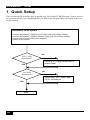
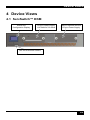
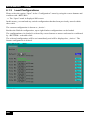
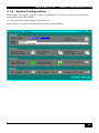
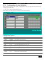
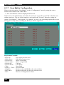
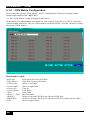
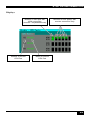
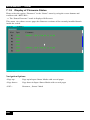
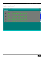
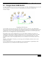
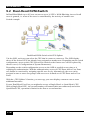
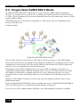
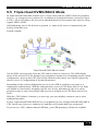
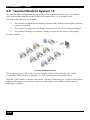
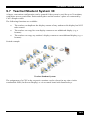
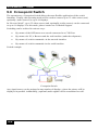
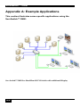
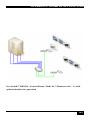
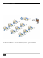
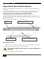
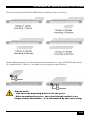
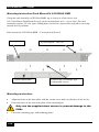
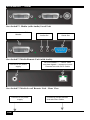
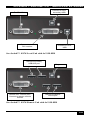
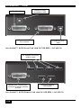
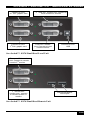
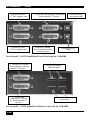
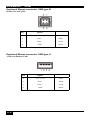
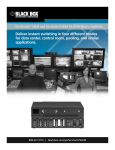
ServSwitch™ DKM
Welcome to the ServSwitch™ Family!
Thank you for purchasing a ServSwitch™ DKM! We appreciate your business, and we think
you’ll appreciate the many ways that your ServSwitch™ DKM will save you money, time,
and effort.
The ServSwitch™ DKM offers four fundamental uses:

As a Crosspoint Switch with a maximum of 32 input ports and 16 output ports.
Optionally, in reverse mode, the device supports a maximum of 16 input ports and
32 output ports. Thus, you can, for example, switch and distribute the signals from
multiple signal sources on up to 32 displays (allowing explicitly simultaneous
presentations on several displays). Alternatively, signals coming from up to 32
signal sources can be switched in turn to a single display. The changeover can be
triggered remotely using the remote control (included), the serial interface (RS232)
and/or by the built-in web interface.

As a KVM Switch with a maximum of 32 CPU ports and 16 Console ports. The
ports can be configured as Single-Head ports (a “Single-Head” extender system
supports 1x monitor, 1x keyboard, 1x mouse), Dual-Head ports (a Dual-Head
extender system supports 2x monitor, 1x keyboard, 1x mouse) or even Quad-Head
ports (a Quad -Head extender system supports 4x monitor, 1x keyboard, 1x mouse).
The changeover can be triggered remotely using the remote control (included), the
serial interface (RS232) and/or by the built-in web interface.

In KVM Switch Mode CPU Ports and CON Ports can be configured as USB2.0
Ports. This can be done for single Ports as well as for combinations of one SingleHead (Triple-Head-)Port and one USB2.0 Port. In the latter case the respective
consoles will always be switched together with its assigned USB2.0 Port.

As a special case of the KVM Switch, you can choose the “Control Room” Mode
with 2, 4 or 8 monitors. In “Control Room” Mode, up to 8 CPU’s are permanently
displayed on up to 8 monitors. With a hotkey, you can switch to any of these
monitors for operation.

In “Teacher/Student” Mode, the teacher can attend up to 31 students.
The ServSwitch™ DKM has the advantage that it can be positioned (CATx version) up to
140m away from both your signal source and display device. This becomes possible by using
the proven ServSwitch™- Extender technology for the transmission of DVI- Monitor and
USB-Keyboard and Mouse signals over CATx cable.
The operation of a ServSwitch™ DKM always requires up to 32 Local Units and up to 16
Remote Units from the ServSwitch™-Extenders range.
1
ServSwitch™ DKM
Wherever long distances cause problems for remotely locating and switching a monitor
(keyboard/mouse) signal, e.g. airports, industrial plants, call centres or in distributed
computer centres, the ServSwitch™ DKM is the best solution to distribute and switch
monitor (keyboard/mouse) signals. Its flexibility allows it to tackle almost every task.
There are 8 pre-configured ServSwitch™ DKMes for CATx as well as an empty chassis for
individual configuration. In addition, there are 4 Media Extenders (DVI + optional audio) and
8 KVM- Extenders (DVI+USB keyboard mouse + optional audio) available. The
transmission of the signals requires connecting CATx cable.
For fibre applications, all switch elements and extenders are also available in multimode or
singlemode versions, requiring the respective cabling.
This manual will tell you all about your new ServSwitch™ DKM, including how to install,
operate and troubleshoot it. For an introduction to the device, see Chapter 2.
The product codes covered in this manual are:
ServSwitch™ DKM Devices for CATx
ACX0808: ServSwitch™ DKM for 8 User and 8 CPUs
ACX0816: ServSwitch™ DKM for 8 User and 16 CPUs
ACX0824: ServSwitch™ DKM for 8 User and 24 CPUs ***
ACX0832: ServSwitch™ DKM for 8 User and 32 CPUs
ACX1608: ServSwitch™ DKM for 16 User and 8 CPUs***
ACX1616: ServSwitch™ DKM for 16 User and 16 CPUs
ACX1624: ServSwitch™ DKM for 16 User and 24 CPUs***
ACX1632: ServSwitch™ DKM for 16 User and 32 CPUs
ACX0000: ServSwitch™ DKM for individual configuration
ServSwitch™ DKM Devices for Multimode/Singlemode and ***marked versions… to
be individually configured, deriving from ACX0000 or others
2
ServSwitch™ DKM
CATx Local and Remote Units
ACS4100A-T: ServSwitch™-Media Local Unit
ACS4122A-T: ServSwitch™-Media Local Unit, +Audio
ACS4001A-T: ServSwitch™- KVM Local Unit, Single-Head
ACS4201A-T: ServSwitch™- KVM Local Unit, Dual-Head
ACS4022A-T: ServSwitch™- KVM Local Unit, +Audio, Single-Head
ACS4222A-T: ServSwitch™- KVM Local Unit, +Audio, Dual-Head
ACS4004A-T: ServSwitch™-KVM Local Unit, Single-Head, 4x USB-HID
ACS4204A-T: ServSwitch™-KVM Local Unit, Dual-Head, 4x USB-HID
ACS4002A-T: ServSwitch™- KVM Local Unit, +USB2.0, Single Head
ACS4011A-T: ServSwitch™- KVM Local Unit, +VGA, Single-Head
ACS4100A-R: ServSwitch™-Media Remote Unit
ACS4122A-R: ServSwitch™-Media Remote Unit, +Audio
ACS4001A-R: ServSwitch™- KVM Remote Unit, Single-Head
ACS4201A-R: ServSwitch™- KVM Remote Unit, Dual-Head
ACS4022A-R: ServSwitch™- KVM Remote Unit, +Audio, Single-Head
ACS4222A-R: ServSwitch™- KVM Remote Unit, +Audio, Dual-Head
ACS4004A-R: ServSwitch™-KVM Remote Unit, Single-Head, 4x USB-HID
ACS4204A-R: ServSwitch™-KVM Remote Unit, Dual-Head, 4x USB-HID
ACS4002A-R: ServSwitch™- KVM Remote Unit, +USB2.0, Single Head
3
ServSwitch™ DKM
Multimode Local and Remote Units
ACS4100A-T-MM: ServSwitch™-Media Local Unit
ACS4122A-T-MM: ServSwitch™-Media Local Unit, +Audio
ACS4001A-T-MM: ServSwitch™- KVM Local Unit, Single-Head
ACS4201A-T-MM: ServSwitch™- KVM Local Unit, Dual-Head
ACS4022A-T-MM: ServSwitch™- KVM Local Unit, +Audio, Single-Head
ACS4222A-T-MM: ServSwitch™- KVM Local Unit, +Audio, Dual-Head
ACS4004A-T-MM: ServSwitch™-KVM Local Unit, Single-Head, 4x USB-HID
ACS4204A-T-MM: ServSwitch™-KVM Local Unit, Dual-Head, 4x USB-HID
ACS4002A-T-MM: ServSwitch™- KVM Local Unit, +USB2.0, Single Head
ACS4011A-T-MM: ServSwitch™- KVM Local Unit, +VGA, Single-Head
ACS4100A-R-MM: ServSwitch™-Media Remote Unit
ACS4122A-R-MM: ServSwitch™-Media Remote Unit, +Audio
ACS4001A-R-MM: ServSwitch™- KVM Remote Unit, Single-Head
ACS4201A-R-MM: ServSwitch™- KVM Remote Unit, Dual-Head
ACS4022A-R-MM: ServSwitch™- KVM Remote Unit, +Audio, Single-Head
ACS4222A-R-MM: ServSwitch™- KVM Remote Unit, +Audio, Dual-Head
ACS4004A-R-MM: ServSwitch™-KVM Remote Unit, Single-Head, 4x USBHID
ACS4204A-R-MM: ServSwitch™-KVM Remote Unit, Dual-Head, 4x USBHID
ACS4002A-R-MM: ServSwitch™- KVM Remote Unit, +USB2.0, Single Head
4
ServSwitch™ DKM
Singlemode Local and Remote Units
ACS4100A-T-SM: ServSwitch™-Media Local Unit
ACS4122A-T-SM: ServSwitch™-Media Local Unit, +Audio
ACS4001A-T-SM: ServSwitch™- KVM Local Unit, Single-Head
ACS4201A-T-SM: ServSwitch™- KVM Local Unit, Dual-Head
ACS4022A-T-SM: ServSwitch™- KVM Local Unit, +Audio, Single-Head
ACS4222A-T-SM: ServSwitch™- KVM Local Unit, +Audio, Dual-Head
ACS4004A-T-SM: ServSwitch™-KVM Local Unit, Single-Head, 4x USB-HID
ACS4204A-T-SM: ServSwitch™-KVM Local Unit, Dual-Head, 4x USB-HID
ACS4002A-T-SM: ServSwitch™- KVM Local Unit, +USB2.0, Single Head
ACS4011A-T-SM: ServSwitch™- KVM Local Unit, +VGA, Single-Head
ACS4100A-R-SM: ServSwitch™-Media Remote Unit
ACS4122A-R-SM: ServSwitch™-Media Remote Unit, +Audio
ACS4001A-R-SM: ServSwitch™- KVM Remote Unit, Single-Head
ACS4201A-R-SM: ServSwitch™- KVM Remote Unit, Dual-Head
ACS4022A-R-SM: ServSwitch™- KVM Remote Unit, +Audio, Single-Head
ACS4222A-R-SM: ServSwitch™- KVM Remote Unit, +Audio, Dual-Head
ACS4004A-R-SM: ServSwitch™-KVM Remote Unit, Single-Head, 4x USBHID
ACS4204A-R-SM: ServSwitch™-KVM Remote Unit, Dual-Head, 4x USB-HID
ACS4002A-R-SM: ServSwitch™- KVM Remote Unit, +USB2.0, Single Head
5
ServSwitch™ DKM
Copyrights and Trademarks
©2009. All rights reserved. This information may not be reproduced in any manner without
the prior written consent of the manufacturer.
Information in this document is subject to change without notice and the manufacturer shall
not be liable for any direct, indirect, special, incidental or consequential damages in
connection with the use of this material.
All trademark and trade names mentioned in this document are acknowledged to be the
property of their respective owners.
Disclaimer
While every precaution has been taken in the preparation of this manual, the manufacturer
assumes no responsibility for errors or omissions. Neither does the manufacturer assume any
liability for damages resulting from the use of the information contained herein. The
manufacturer reserves the right to change the specifications, functions, or circuitry of the
product without notice.
The manufacturer cannot accept liability for damage due to misuse of the product or due to
any other circumstances outside the manufacturer’s control (whether environmental or
installation related). The manufacturer shall not be responsible for any loss, damage, or injury
arising directly, indirectly, or consequently from the use of this product.
Cautions and Notes
The following symbols are used in this guide:
CAUTION: This indicates an important operating instruction
that should be followed to avoid any potential damage to
hardware or property, loss of data, or personal injury.
NOTE. This indicates important information to help you make the best use of
this product.
6
EMPTY PAGE
7
ServSwitch™ DKM
EC DECLARATION OF CONFORMITY
The products listed below in the form as delivered are in conformity with the provisions
of the following European Directives:
2004/108/EG Council Directive on the approximation of the laws of the Member States
relating to electromagnetic compatibility
CE-marking 2009
Product list:
List on page 2 - 5
Conformity to the Directives is assured through the application of the following
standards:
EN 55022:
IEC 61000-4-2:
IEC 61000-4-3:
IEC 61000-4-4:
IEC 61000-4-5:
09/2006 Class A
02/2001
05/2006
12/2004
11/2006
This declaration certifies the conformity to the specified directives but contains no
assurance of properties. The safety documentation noted in this manual shall be
considered in detail. The length of the attached CPU- or Console Cables must not exceed
3m. The use of suggested interconnect cables is mandatory.
Oberteuringen, June 23rd, 2009
The management
manufacturer:
IHSE GmbH
Maybachstrasse 11
88094 Oberteuringen
Germany
WARNING: This equipment has been found to comply with the limits for a Class A digital
device, pursuant to Part 15 of the FCC Rules. These limits are designed to provide reasonable
protection against harmful interference when the equipment is operated in a commercial
environment. This equipment generates, uses, and can radiate radio frequency energy and, if
not installed and used in accordance with the instruction manual, may cause harmful
interference to radio communications. Operation of this equipment in a residential area is
likely to cause harmful interference in which case the user will be required to correct the
interference at his own expense.
8
SAFETY PRECAUTIONS AND
INSTALLATION GUIDLINES
Safety Precautions and Installation Guidelines
To ensure reliable and safe long-term operation, please note the following installation
guidelines:

Do not use CATx- devices to link between buildings – please use fibre devices.

Only use in dry, indoor environments.

If the building has 3-phase AC power, try to ensure that equipment connected to the
Local and Remote Units is on the same phase.

Try not to route a CATx- link cable alongside power cables.

The Remote Unit, Local Unit and any power supplies can get warm. Do not locate them
in an enclosed space without any airflow.

Do not place a power supply directly on top of a unit.

Do not obscure a unit’s ventilation holes.
To safeguard against personal injury and avoid possible
damage to equipment or property, please observe the
following:

Only use power supplies originally supplied with the
product or manufacturer-approved replacements. Do not
attempt to dismantle or repair any power supply. Do not
use a power supply if it appears to be defective or has a
damaged case.

Connect all power supplies to grounded outlets. In each
case, ensure that the ground connection is maintained
from the outlet socket through to the power supply’s AC
power input.

Do not attempt to modify or repair this product, or make
a connection from the CATx- link interface (RJ45) to any
other products, especially telecommunications or
network equipment.
9
ServSwitch™ DKM
Contents
1 Quick Setup
14
2 Overview
15
2.1
2.2
2.3
2.4
2.5
2.6
2.7
Introduction
Glossary 17
Example of a ServSwitch™ DKM System
Features 19
Product Range
Compatibility
How to Use This Guide
2.7.1
2.7.2
2.7.3
2.7.4
Connection & Compatibility
DDC Information
Selecting the moment of switching to the next frame
Selection of Color reduction for transfer acceleration
3 Installation
3.1
3.2
3.3
3.4
Package Contents
Interconnection Cable Requirements
System Setup
Installation Instructions
4 Device Views
4.1 ServSwitch™ DKM
5 Diagnostic
15
18
21
26
27
27
27
27
28
29
29
31
33
34
35
35
37
5.1 ServSwitch™ DKM – I/O Boards
37
6 ServSwitch™ DKM Configuration
39
6.1 Configuration via Console
6.1.1
6.1.2
6.1.3
6.1.4
6.1.5
6.1.6
6.1.7
6.1.8
6.1.9
6.1.10
6.1.11
6.1.12
6.1.13
6.1.14
10
On-Screen Display (OSD)
Open „Configuration“ Menu
Load Configurations
System Configurations
Touch Screen Settings
Configuration of User Attributes
User Matrix Configuration
Configuration of CON Ports
CON Matrix Configuration
Configuration of CPU Ports
Configuration of Network Parameters
Programming of Macros
Saving Configurations inside the Switch
Saving Configurations into File
39
39
44
46
47
52
53
54
56
58
60
61
62
64
65
CONTENTS
6.1.15
Restart your Switch
6.2 Configuration via Browser and Web Interface
6.3 Configuration via Serial Interface
6.4 Configuration via IR Remote Control and LCD-Display
6.4.1
6.4.2
6.4.3
6.4.4
6.4.5
6.4.6
6.4.7
6.4.8
IR Remote Control
Home Mask
Menu Mask
Configuration Mask
Configuration of Network Parameters
Configuration of System Parameters
Restart your Switch
Reset your Switch
6.5 Configuration via FTP
6.5.1
6.5.2
6.5.3
FTP Access to Configuration Files
External Saving of Configuration Files
Loading External Configuration Files
7 Status Information
7.1 Status Display via Console and OSD
7.1.1
7.1.2
7.1.3
7.1.4
7.1.5
Open the „Status“ Menu
Status Display of CON Ports
Status Display of CPU Ports
Display of Network Status
Display of Firmware Status
7.2 Status Display via Browser / Web Interface
7.3 Status Display via Serial- Interface
7.4 Status Display via LCD-Display
7.4.1
7.4.2
7.4.3
7.4.4
7.4.5
7.4.6
7.4.7
Home Mask
Menu Mask
Status Mask
Display of CPU-/CON-Ports Status
Display of Network Status
Display of Flash Status
Display of Tasks Status
8 Control of ServSwitch™ DKM
8.1 Instant Switching
8.1.1
8.1.2
8.1.3
8.1.4
Keyboard Hot Keys
Changing the default Instant Switching Hotkey
Macro Keyboard
Macros via Function keys of a standard keyboard
8.2 Switching in OSD / KVM Mode
8.2.1
8.2.2
8.2.3
Switching in „KVM-List“ Mask:
Switching in „KVM-Switch“ Mask:
Switching in „Follow Me“ Mask:
8.3 Switching in OSD / Crosspoint Mode
8.3.1
8.3.2
8.3.3
Open the „CP-Switch“ Menu
Switching in „Crosspoint Switch / CON Ports“ Mask
Switching in „Crosspoint Switch / CPU Ports“ Mask“
8.4 Switching via Browser / Web Interface
66
67
68
69
69
70
70
71
72
73
75
75
76
76
77
77
78
79
79
80
82
84
86
88
89
90
90
90
91
91
92
94
96
97
98
98
98
99
99
100
100
102
104
105
106
107
109
111
11
ServSwitch™ DKM
8.5 Switching via Serial Interface
8.6 Switching via LCD-Display
9 Operating Modes
9.1
9.2
9.3
9.4
9.5
9.6
9.7
9.8
Single-Head KVM-Switch
Dual-Head KVM-Switch
Quad-Head KVM-Switch
Single-Head KVM/USB2.0 Mode
Triple-Head KVM/USB2.0 Mode
Teacher/Student System 15
Teacher/Student System 30
Crosspoint Switch
10 Troubleshooting
10.1
10.2
Monitor
USB HID
112
113
114
115
116
117
118
119
120
121
122
123
123
124
Appendix A: Example Applications
126
Appendix B: Rack Mount Options
130
Appendix C: Serial Interface
134
Appendix D: Network Interface
139
Appendix E: Calling Technical Support
140
Appendix F: List of supported USB devices
141
Appendix G: Specifications
142
Appendix H: Connectors
144
Appendix I: ServSwitch™ Media/KVM Extender
145
I.1.
I.2.
I.3.
I.4.
I.5.
I.6.
12
ServSwitch™- Media Extender
ServSwitch™- KVM Extender
Diagnostics of ServSwitch™- Media/ KVM
Service Setup Extenders
Setup at the Local Unit
Setup at the Remote Unit
145
148
159
160
161
163
CONTENTS
I.7. Devices with serial/audio option
I.8. Specifications ServSwitch™-Media/KVM Units
I.9. Connectors ServSwitch™-Media/KVM Units
164
166
169
13
ServSwitch™ DKM
1 Quick Setup
This section briefly describes how to install your ServSwitch™ DKM system. Unless you are
an experienced user, we recommend that you follow the full procedures described in the rest
of this manual.
Installation of the system
Connect ServSwitch™ DKM to Local unit(s) with CATx/Fibre cable(s).
Connect ServSwitch™ DKM to Remote unit(s) with CATx/Fibre cable(s).
Connect the devices to the power supplies.
Power up the system.
NO
Power LED
illuminated?
YES
Link LED
illuminated?
NO
Check the CATx- cable, and
CATx- connectors
YES
Done
14
Check p.s.u.’s and connection to
power outlet
OVERVIEW
2 Overview
2.1 Introduction
The ServSwitch™ DKM can be set up to support four different applications:

Crosspoint Switch: Maximum configuration (without cascading) of 32 input ports
and 16 output ports. Optionally, in reverse mode, the device supports a maximum
of 16 input ports and 32 output ports.
Set-Up: Local units are installed at up to 32 DVI signal sources. The Crosspoint
Switch may now be installed up to 10 km away from the sources.
The received signals (DVI + optional serial/Audio) can now be switched to the
respective output ports. One input signal may be distributed simultaneously to
several output ports.
From these output ports, the displays (again, up to 10 km away) are controlled via
remote units to be installed at each display. The changeover can be triggered
remotely using the serial interface (RS232) and/or by the built-in web interface.

KVM Switch: As a KVM Switch the device supports several operation modes:
16 User ports on 32 CPU ports for Single-Head access, 8 User ports on 16 CPU
ports for Dual-Head access or even 4 User ports on 8 CPU ports for Quad-Head
access.
Single-Head/ Dual-Head/ Quad-Head CPUs/ and User ports may also be operated
in mixed mode. In this case, the maximum number of User ports depends on the
detailed configuration.
A maximum of 32 CPUs (up to 10 km away) can be connected to the KVM Switch
via Local units to be installed at each CPU.
The received signals (DVI, Keyboard, Mouse + optional serial/Audio) can now be
switched to the respective output ports. From these output ports, up to 16 consoles
(again, up to 10 km away) are controlled via remote units to be installed at each
console.
The changeover can be triggered remotely by a hotkey sequence (only in KVM
mode), using the serial interface (RS232) or by the built-in web interface.
A comfortable OSD (On Screen Display) allows the selection of the CPUs, user
administration and offers further administrative functions.
A special function called “Partner Viewing” allows copying one (or more) display
signal(s) to one or more additional displays. This mode is especially useful e.g. if
one display signal shall be shown on both the user display and a beamer or if the
monitor information shall be shared with an administrator. The “Follow Me”
function ensures that the monitor information is updated whenever the original
display signal source is changed.
15
ServSwitch™ DKM

“Control Room” Mode: As a special case of the KVM Switch, you can choose
the “Control Room” Mode. In this mode, several displays are assigned to a work
place. A comfortable OSD (On Screen Display) allows at any time to choose from a
list of available CPUs the CPU to be displayed on a specific monitor.
With a hotkey sequence, you can switch keyboard and mouse to any of these
monitors for operation without need to know the associated CPU. Now you can
operate this CPU.
Also in this mode, one (or more) display signal(s) can be copied to one or more
additional displays (“Partner Viewing”).

“Teacher/Student” System: Two configurations are available:
a) Attend up to 15 Students – Each student work place is connected by CATxDuplex cable. Each CPU can be displayed at any work place – both student and
teacher work place – even simultaneously. The teacher can observe every student
work place.
b) Attend up to 31 Students – Each student work place is connected by CATxSimplex cable. Each CPU can be displayed at a specific monitor, e.g. beamer or
large display – both student and teacher work place. The teacher can observe every
student work place.
A ServSwitch™ DKM system comprises a ServSwitch™ DKM and one or more
Local/Remote Units. The ServSwitch™ DKM and the Local/ Remote Units are attached by
CATx or Fibre interconnection cables.
The operation of a ServSwitch™ DKM requires always the use of Local Units and Remote
Units of a ServSwitch™-Extender.
16
OVERVIEW
2.2 Glossary
The following terms are used in this guide:
CATx
Any Category 5, 5e, 6 or higher cable, solid wires type AWG24.
If Patch Cables are used, all distances count twice.
Fibre
Singlemode or Multimode fibre cable.
Singlemode
9µ Singlemode fibre cable.
Multimode
62,5µ Multimode- or 50µ Multimode fibre cable.
KVM
Keyboard, Video and Mouse.
Console
Keyboard, Mouse and Monitor
Dual Access
A system allowing connection of Local and Remote User Consoles.
Single-Head
An extender system that supports one Monitor + Keyboard/ Mouse
Dual-Head
An extender system that supports two Monitors + Keyboard/ Mouse
Quad-Head
An extender system that supports four Monitors + Keyboard/ Mouse
DVI
Digital Video standard, installed by Digital Display Working Group
(www.ddwg.org) R, G, B, CLOCK in a data stream with up to
3x1,6 Gbit/sec. Signals are TMDS Level.
PSU
The desktop power supply connected to the ServSwitch™ DKM or to
the Local/ Remote Unit.
HID
Human Interface Devices are units, which are used for human access
to the CPU: keyboard and mouse, touch-screen, light pen, fingerprint
sensor, graphic tablets etc.
17
ServSwitch™ DKM
2.3 Example of a ServSwitch™ DKM System
Application example for a ServSwitch™ DKM System
(Single-Head KVM Switch)
18
OVERVIEW
2.4 Features
The ServSwitch™ DKM offers the following features:

Support for DVI-D Graphic cards (all devices)

Support for USB-Keyboard and USB-Mouse (KVM-Extender)
ServSwitch™- KVM standard devices with USB-HID connectors support
the extension of keyboard and mouse ONLY; use with other HID devices
(Human Interface Device) such as touch screens, graphics tablets, barcode
readers or similar may be successful – but there is no guarantee for this!
The ServSwitch™- KVM standard device is NOT suitable for use with
other USB- devices such as scanners, web- cams, data sticks etc.
ServSwitch™- KVM standard devices support only two devices
simultaneously – keyboard and mouse or keyboard and touch-screen, etc.
but not e.g. keyboard, mouse and touch-screen simultaneously. You can
extend by a USB hub but this does not raise the number of supported
devices.

Maximum length of interconnection cable from a Local Unit to a ServSwitch™- Minor
Switch, between two ServSwitch™- Minor Switches or from a ServSwitch™- Minor
Switch to a Remote Unit).




140m (400ft) with CATx- cable
200 m mit Multimode 62.5μm
400 m mit Multimode 50μm
10.000 m mit Singlemode 9μm

Maximum Resolution (DVI): 1920x1200@60Hz

Supports:16/24 Bit auto-switching or 24 Bit (= full) color depth (selectable)

Status indicator LEDs for Power and Link on each device.

Compact footprint chassis.

Rack mount options available.

International power supplies included.

Options:



USB 2.0 Support
Bidirectional Audio Interface
Serial Interface
 Single-Head Devices support a transparent serial interface with up to 19.2
KBaud and Hardware handshake. This serial interface can be used to control a
single device requiring full Hardware handshake or up to three devices without
Handshake (XON/XOFF)
19
ServSwitch™ DKM

20
Dual-Head Devices support TxD and RxD ONLY – no Hardware handshake
(XON/XOFF)
OVERVIEW
2.5 Product Range
The following products are available as well as various upgrade kits:
ServSwitch™ DKM and Accessories
ACX0808
ServSwitch™ DKM for 8 Users and 8 CPUs (CATx)
ACX0816
ServSwitch™ DKM for 8 Users and 16 CPUs (CATx)
ACX0824
ServSwitch™ DKM for 8 Users and 24 CPUs (CATx)
ACX0832
ServSwitch™ DKM for 8 Users and 32 CPUs (CATx)
ACX1608
ServSwitch™ DKM for 16 Users and 8 CPUs (CATx)
ACX1616
ServSwitch™ DKM for 16 Users and 16 CPUs (CATx)
ACX1624
ServSwitch™ DKM for 16 Users and 24 CPUs (CATx)
ACX1632
ServSwitch™ DKM for 16 Users and 32 CPUs (CATx)
ACX0000
ServSwitch™ DKM empty (consisting of housing, base
PCB, Controler Board and 1x p.s.u. (slide in version) for
customized assembly
ACXPSR
P.s.u. (slide in version) for spare or for upgrade to
redundant p.s.u.
ACX8OSD
ServSwitch™ DKM OSD Board
ACXDIS
ServSwitch™ DKM Display Board
ACX8CAT
ServSwitch™ DKM CATx I/O Board
ACX8SFP
ServSwitch™ DKM I/O Board empty, for customized
assembly
ACXSFPC
CATx GBIC for use with ACX8SFP
ACXSFPM
Multimode GBIC for use with ACX8SFP
ACXSFPS
Singlemode GBIC for use with ACX8SFP
21
ServSwitch™ DKM
Media Extenders
ACS4100A-T
ServSwitch™-Media Local Unit (CATx)
ACS4122A-T
ServSwitch™-Media Local Unit + Audio (CATx)
ACS4100A-R
ServSwitch™-Media Remote Unit (CATx)
ACS4122A-R
ServSwitch™-Media Remote Unit + Audio (CATx)
ACS4100A-T-MM
ServSwitch™-Media Local Unit (Multimode)
ACS4122A-T-MM
ServSwitch™-Media Local Unit + Audio (Multimode)
ACS4100A-R-MM
ServSwitch™-Media Remote Unit (Multimode)
ACS4122A-R-MM
ServSwitch™-Media Remote Unit + Audio (Multimode)
ACS4100A-T-SM
ServSwitch™-Media Local Unit (Singlemode)
ACS4122A-T-SM
ServSwitch™-Media Local Unit + Audio (Singlemode)
ACS4100A-R-SM
ServSwitch™-Media Remote Unit (Singlemode)
ACS4122A-R-SM
ServSwitch™-Media Remote Unit + Audio (Singlemode)
KVM Extenders for CATx
ACS4001A-T
ServSwitch™-KVM Local Unit, Single-Head
ACS4201A-T
ServSwitch™-KVM Local Unit, Dual-Head
ACS4022A-T
ServSwitch™-KVM Local Unit, + Audio, Single-Head
ACS4222A-T
ServSwitch™-KVM Local Unit, + Audio, Dual-Head
ACS4004A-T
ServSwitch™-KVM Local Unit, Single-Head, 4x USBHID
ACS4204A-T
ServSwitch™-KVM Local Unit, Dual-Head, 4x USB-HID
ACS4002A-T
ServSwitch™-KVM Local Unit, Single-Head, 4x USB-2.0
ACS4011A-T
ServSwitch™-KVM Local Unit, DVI-I Input (VGA)
ACS4001A-R
ServSwitch™-KVM Remote Unit, Single-Head
ACS4201A-T
ServSwitch™-KVM Remote Unit, Dual-Head
ACS4022A-T
ServSwitch™-KVM Remote Unit, + Audio, Single-Head
ACS4222A-R
ServSwitch™-KVM Remote Unit, + Audio, Dual-Head
ACS4004A-R
ServSwitch™-KVM Remote Unit, Single-Head, 4x USBHID
ACS4204A-R
ServSwitch™-KVM Remote Unit, Dual-Head, 4x USBHID
ACS4002A-R
ServSwitch™-KVM Remote Unit, Single-Head, 4x USB-
22
OVERVIEW
2.0
23
ServSwitch™ DKM
KVM Extenders for Multimode
ACS4001A-T-MM
ServSwitch™-KVM Local Unit, Single-Head
ACS4201A-T-MM
ServSwitch™-KVM Local Unit, Dual-Head
ACS4022A-T-MM
ServSwitch™-KVM Local Unit, + Audio, Single-Head
ACS4222A-T-MM
ServSwitch™-KVM Local Unit, + Audio, Dual-Head
ACS4004A-T-MM
ServSwitch™-KVM Local Unit, Single-Head, 4x USB-
ACS4204A-T-MM
ServSwitch™-KVM Local Unit, Dual-Head, 4x USB-HID
ACS4002A-T-MM
ServSwitch™-KVM Local Unit, Single-Head, 4x USB-2.0
ACS4011A-T-MM
ServSwitch™-KVM Local Unit, DVI-I Input (VGA)
ACS4001A-R-MM
ServSwitch™-KVM Remote Unit, Single-Head
ACS4201A-R-MM
ServSwitch™-KVM Remote Unit, Dual-Head
ACS4022A-R-MM
ServSwitch™-KVM Remote Unit, + Audio, Single-Head
ACS4222A-R-MM
ServSwitch™-KVM Remote Unit, + Audio, Dual-Head
ACS4004A-R-MM
ServSwitch™-KVM Remote Unit, Single-Head, 4x USB-
ACS4204A-R-MM
ServSwitch™-KVM Remote Unit, Dual-Head, 4x USB-
ACS4002A-R-MM
ServSwitch™-KVM Remote Unit, Single-Head, 4x USB-
KVM Extenders for Singlemode
ACS4001A-T-SM
ServSwitch™-KVM Local Unit, Single-Head
ACS4201A-T-SM
ServSwitch™-KVM Local Unit, Dual-Head
ACS4022A-T-SM
ServSwitch™-KVM Local Unit, + Audio, Single-Head
ACS4222A-T-SM
ServSwitch™-KVM Local Unit, + Audio, Dual-Head
ACS4004A-T-SM
ServSwitch™-KVM Local Unit, Single-Head, 4x USB-
ACS4204A-T-SM
ServSwitch™-KVM Local Unit, Dual-Head, 4x USB-HID
ACS4002A-T-SM
ServSwitch™-KVM Local Unit, Single-Head, 4x USB-2.0
ACS4011A-T-SM
ServSwitch™-KVM Local Unit, DVI-I Input (VGA)
ACS4001A-R-SM
ServSwitch™-KVM Remote Unit, Single-Head
ACS4201A-R-SM
ServSwitch™-KVM Remote Unit, Dual-Head
ACS4022A-R-SM
ServSwitch™-KVM Remote Unit, + Audio, Single-Head
ACS4222A-R-SM
ServSwitch™-KVM Remote Unit, + Audio, Dual-Head
ACS4004A-R-SM
ServSwitch™-KVM Remote Unit, Single-Head, 4x USB-
ACS4204A-R-SM
ServSwitch™-KVM Remote Unit, Dual-Head, 4x USB-
ACS4002A-R-SM
ServSwitch™-KVM Remote Unit, Single-Head, 4x USB-
24
OVERVIEW
Upgrade Kits
ACS1009A-RMK
19”/1HE rack mount kit to mount up to 4 Single-Head
devices
ACS2209A-RMK
19”/1HE rack mount kit to mount up to 4 Dual-Head
devices/ SERVSWITCH™ DKM devices
ACS2209A-PS
19“mountable power supply for up to three
SERVSWITCH™ DKM devices.
ACS1009A-SMK
Mounting plate to mount by screws
DRMACU-S
DIN Rail Mounting plate to mount by snap on
Accessories
AC1038A
DVI-D to VGA Converter, to connect the local output to a
traditional VGA-KVM-Switch
ACXCWDM4
CWDM MUX/DEMUX to send up to 4 ServSwitch™ fiber
interconnections simultaneously over only two fibres
ACX1000
CATx Repeater to double the maximum allowed distance
to up to 280m (also available for Multi-/Singlemode)
ACX1000-CM
CATx/Multimode Cross Repeater to convert from CATx to
Multimode or back (also available for Singlemode)
ACX1000-MS
Multimode/Singlemode Cross Repeater to convert from
Multimode to Singlemode
25
ServSwitch™ DKM
2.6 Compatibility
Interface Compatibility

Digital Video (DVI-D): Digital Video standard, installed by Digital Display Working
Group (www.ddwg.org) R, G, B, CLOCK in a data stream with up to 3x 1,6 Gbit/sec.
Signals are TMDS Level.

USB Keyboard: Compatible with all standard keyboards. Certain keyboards with
enhanced features may also be supported with custom firmware. Keyboards with built-in
hub are also supported – but there are never more than two HID devices supported.

USB Mouse: Compatible with all standard 2-button, 3-button and wheel mice.
ServSwitch™- KVM standard devices with USB-HID connectors support
the extension of keyboard and mouse ONLY; use with other HID devices
(Human Interface Device) such as touch screens, graphics tablets, barcode
readers or similar may be successful – but there is no guarantee for this!
The ServSwitch™- KVM standard device is NOT suitable for use with
other USB- devices such as scanners, web- cams, data sticks etc.
ServSwitch™- KVM standard devices support only two devices
simultaneously – keyboard and mouse or keyboard and touch-screen, etc.
but not e.g. keyboard, mouse and touch-screen simultaneously. You can
extend by a USB hub but this does not raise the number of supported
devices.

Fibre-/CATx Devices: A ServSwitch™ Switch may be equipped with both CATx
GBICs and fibre GBICs. This allows to switch both fibre and CATx Signals with one
ServSwitch™ Switch.
Currently, it is NOT possible to connect devices of different
topologies (CATx and fibre). The related signals are switched
correctly but the data format is not compatible. If this
feature is required, please consider using our CrossRepeater. Our technical support will assist you (cf. Appendix
E: Calling Technical Support Page 140).
26
OVERVIEW
2.7 How to Use This Guide
This guide describes the installation and configuration of the ServSwitch™ DKM. Although
the connection and operation of the system is relatively straightforward, you should consider
the following before getting started:
2.7.1
Connection & Compatibility
The individual ServSwitch™ DKM components consist of:

ServSwitch™ DKM includes the device and power supply.

ServSwitch™- KVM/ Media Local Unit: includes the device, power supply and all
cables required to connect the ServSwitch™- KVM/ Media Local Unit to your CPU/
Signal source.

ServSwitch™- KVM/ Media Remote Unit: includes the device and power supply
Please see also Package Contents (Page 29).
For information about connection and installation, see page 31.
2.7.2
DDC Information
Normally, it is not necessary to make any adjustments to the ServSwitch™- KVM/ Media
device. However, in some circumstances, it may be necessary to redefine the source of DDC
information for the CPU. By default, the ServSwitch™- KVM/ Media device uses its own
internal DDC table. If this setting does not satisfy your requirements, the DDC table can
either be switched to the DDC table of the locally attached screen or can be downloaded from
the remotely located screen and stored in the internal DDC table.
Default: Download from Remote Monitor
To modify the DDC Setup, see Loading the DDC information from the remote monitor (Page
161).
2.7.3
Selecting the moment of switching to the next frame
The transmission of screen data is not synchronous to the screen changes of the graphic card.
Normally, the transmission is terminated during the display of a frame on the screen (at the
remote unit). If the device switches to the new frame during the displaying period of the old
frame (somewhere on the screen), it is possible that you will see horizontal screen breaks at
the moment of switching (default). On the other hand, if the device idles until the actual
frame is displayed completely (until VSYNC) then the number of frames per second
transmitted may be reduced.
To modify the switching behaviour, see Setup at the Remote Unit (Page 163).
27
ServSwitch™ DKM
2.7.4
Selection of Color reduction for transfer acceleration
You can select, whether always 24 Bit colors (=full color depth) are transmitted or whether
the compression algorithm automatically switches between 16 and 24 Bit colors to accelerate
the data transfer (default). Normally the difference between 24 Bit and 16 Bit is not
recognizable but under some special circumstances e.g. in photo processing installations there
might be disturbing color abberations. While the automatic color switching enhances the
number of frames, transmitted per second, fixed 24 Bit color depth gives smooth color grades
under all circumstances. Please select your preferred mode.
To modify the color depth, see Setup at the Local Unit (Page 161).
28
INSTALLATION
3 Installation
For first-time users, we recommend that you carry out a test placement, confined to a single
room, before commencing full installation. This will allow you to identify and solve any
cabling problems and experiment with the ServSwitch™ DKM System more conveniently.
3.1 Package Contents
You should receive the following items in your ServSwitch™ DKM for CATx package:

ServSwitch™ DKM

1x 5V DC universal power supply for the ServSwitch™ DKM

1x German type power cord

1x USB (1.8m) cable (USB type A to type B)

1x IR Remote Control

User manual (Quick Setup)

CDROM with utilities and complete User Manual
The following parts should be in your ServSwitch™- KVM/ Media Local Unit package:

ServSwitch™- KVM/ Media Local Unit

1x 5V DC universal power supply for the ServSwitch™- Minor KVM/ Media Local
Unit

1x German type power cord

DVI-I (1.8m) video cable (DVI male-to-male)

User manual (Quick Setup)
Additionally with the Dual-Head devices:

DVI-I (1.8m) video cable (DVI male-to-male)
29
ServSwitch™ DKM
Additionally with the ServSwitch™-KVM devices:

USB (1.8m) cable (USB type A to type B)
Additionally with the ServSwitch™-Media/ KVM devices +audio:

Serial cable 1.8m (Serial DB9-male/female)

2 audio cables 1.8m
Additionally with the ServSwitch™- KVM Dual-Head and Media Devices + Audio:

Serial/Audio Combo cable (1,8m) –DSUB9 female and 2x 3,5mm Stereo Jacks on one
side, 8pol. miniDIN male
The following parts should be in your ServSwitch™- KVM/ Media Remote Unit
package:

ServSwitch™- KVM/ Media Remote Unit

1x 5V DC universal power supply for the ServSwitch™- KVM/ Media Remote Unit

1x German type power cord

User manual (Quick Setup)
If anything is missing, please contact our Technical Support (see Appendix E: Calling
Technical Support on page 140)
30
INSTALLATION
3.2 Interconnection Cable Requirements
To connect the ServSwitch™-Media Local Unit to your CPU/signal source you will need
(Please ensure that the connection is tension-free!):
DVI: Connect the supplied DVI-cable 1.8m (DVI-I male to DVI-I male) to your CPU
(KVM- Switch, DVI- signal source, etc.).
USB: Connect the supplied USB- cable 1.8m (USB Type A to USB Type B) to your CPU
(KVM- Switch, DVI- signal source, etc.).
Serial /Audio (Combo) cable: Connect the supplied Serial/Audio (Combo) cable to your
CPU/signal source (DVI male to DVI male, serial DB9 male/female and Audio).
Serial cable: Connect the supplied Serial cable to your CPU/signal source (DB9 male to
DB9 female).
Audio cable: Connect the supplied Audio cable to your CPU/signal source (2x 3,5 Stereo
Audio jacks).
CATx Cable: Recommended cable: S/UTP (Cat5) according EIA/TIA 56A, TSB 36 or
Digital STP 17-03170. Four pairs AWG 24. Wiring according EIA/TIA 568A (10BaseT). Use
of cables from a higher category (Cat5e, Cat6, Cat7) is possible.
The use of unshielded CATx- cable is possible; because of the higher
electromagnetic noise/sensitivity, the device class may not be reached.
You may use flexible cables (patch cable) type AWG26/7 but because of the
higher loss of the stranded cables, the maximum extension distance is
reduced to approximately half the value of solid cables.
A point-to-point connection is required. You may use one or more patch
panels in the line. Do not connect the CATx- link interface (RJ45) to any
other products, especially telecommunications or network equipment.
31
ServSwitch™ DKM
Fibre optical cable: Two fibres are required for Single-Head transmission and four fibres
for Dual-Head transmission.
The achievable distance depends on both the cable type and the device
type.

Recommended cables:
Multimode Type 50/125µ
Multimode Type 62.5/125µ
Singlemode Type 9/125µ
Achievable Distance approx. 400m (1,300ft)
Achievable Distance approx. 200m (650ft)
Achievable Distance approx. 10km (32,750ft)
A point-to-point connection is required. You may use one or more patch
panels in the line. Do not connect the Fiber- link interface (LC-duplex) to
any other products, especially telecommunications or network equipment.
Empirically, Singlemode devices work well with Multimode cables but not
vice versa. Furthermore, Singlemode devices with Multimode cables might
double the achievable distance via Multimode cable! This cannot be
guaranteed, however, and must be verified by the user at own risk and cost.
Power Supply: Connect the supplied 5V/DC power supply to the ‘POWER’ socket of the
ServSwitch™ Local Unit or ServSwitch™ Remote Unit.
32
INSTALLATION
3.3 System Setup
To install your ServSwitch™ DKM system:
1.
Switch off all devices.
2.
Connect keyboard, monitor(s), mouse to the Remote Unit (depending on device type).
3.
Connect the CPU/signal source to the Local Unit using the supplied cable(s).
4.
Connect the ServSwitch™ Local units and Remote units with the INTERCONNECT
cable(s) (CATx or Fibre)
5.
Connect the ServSwitch™ DKM with the INTERCONNECT cable(s) (CATx / Fibre)
6.
Type 474-8X only: Equip the Cage sockets with GBICs according to your desired
configuration.
7.
Depending upon your application, it may be necessary to make a connection to a
controller over the serial interface. Attach the provided RJ45 to DSUB 9-pin cable at the
socket of the serial interface and connect it with your controller. More information for
control through the serial interface can be found in Appendix C: Serial Interface on
page 139.
8.
Connect the 5V power supplies to the units.
Only use the power supply originally supplied with this
equipment or a manufacturer-approved replacement.
9.
For a dual access system, connect the monitor for the local console to the appropriate
port on the Local Unit. The port may also be used to feed into a KVM switch.
To attach a local (USB-) keyboard/mouse, please use additional USB port(s) at your
CPU or use a USB hub between the CPU and Local Unit’s USB- connector.
10. Power up the system.
11. Login at any console as Administrator
12. Configure your system
13. Done!
33
ServSwitch™ DKM
3.4 Installation Instructions
Please ensure that the ServSwitch DKM has sufficient ventilation space by ensuring the
following distances between the unit and other devices and/or mounting parts:
Space directions while putting the device onto a desk
Space directions while mounting the device into a 19” rack
The ServSwitch™ DKM, its extenders and power supplies
may become warm. Do not install the unit in closed areas
without adequate ventilation.
Never place the power supplies on top of the devices.
Ensure that the existing ventilation openings on the device
are free at all times.
34
DEVICE VIEWS
4 Device Views
4.1 ServSwitch™ DKM
Status and
Configuration Display
Plug-in Power Supply
100-240VAC 50-60Hz
Bay for optional second
Plug-in Power Supply
Slot for IR Remote Control
35
ServSwitch™ DKM
Connect to Local
Units (CPU)
Network, Serial, USB
Interfaces
Connect to AC Power
Supply
Connect to Remote
Units (Console)
Rear View with two AC Sockets for redundant
Power Supply
36
DIAGNOSTIC
5 Diagnostic
5.1 ServSwitch™ DKM – I/O Boards
Each ServSwitch™ DKM I/O Board is fitted with indicator LEDs for status diagnostics.
The location of the LEDs is shown below:
Diagnostic LED
Link Status
Left Socket
Diagnostic LED
Link Status
Right Socket
Diagnostic LED
Link Status
Left Socket
Diagnostic LED
Link Status
Right Socket
Diagnostic LEDs at CATx I/O Boards
The Link Status LEDs are at the left CATx- sockets in the upper and lower corner. The LEDs
in the upper corners show the status for the left CATx- connection, the lower LEDs for the
right CATx- connection.
LED
Appearance
Diagnostics
Link Status
(Green / Orange
LED)
Green blinking
CATx cable connection OK
Data transmission active
CATx cable connection OK
No data transmission
Port active, no CATx cable connection
(no cable, cable defective, local / remote unit off or
attached to wrong port)
Port deactivated
Green On
Orange blinking
Off
37
ServSwitch™ DKM
Diagnostic LEDs at Fibre I/O Boards
The Link Status LED are located between the upper and the lower fibre sockets.
The
LED indicates the status of the left connection, the
LED indicates the status of
the right connection.
LED
Appearance
Diagnostics
Link Status
(Green / Red
LED)
Green blinking
Green On
Red blinking
Green On
OFF
Port activated, signal OK.
Port deactivated, signal OK
Port activated, no signal detected
Port activated, module error signal.
Port deactivated.
38
SERVSWITCH™ DKM CONFIGURATION
6 ServSwitch™ DKM Configuration
The ServSwitch™ DKM has an own operating system that can be configured in five different
ways:

By means of a console connected to a console port and the On-Screen Display
(OSD)

By means of a PC, a Browser and the web interface (under development)

By means of a PC and the serial interface (under development, limited
functionality)

By means of the supplied IR Remote Control at the LCD-Display (limited
functionality)

By means of externally stored configuration files and the FTP interface
6.1 Configuration via Console
With the OSD, the ServSwitch™ DKM can be completely configured from any console. In
the following, settings in the menu “configuration” are described. All other menus are
described in later chapters.
6.1.1
6.1.1.1
On-Screen Display (OSD)
Enter into the OSD
Enter into the OSD by simultaneously pressing the following button combination:
<Strg>+ <Shift>+ <O> (Letter ‚o’)
Please note: on many keyboards, the <STRG>- button is
indicated by <CTRL>.
The character input is NOT case-sensitive.
<SHIFT> indicates the button for capital letters.
<Button1>+< Button2>+ … means that all buttons must be
pressed simultaneously
<Button1>,< Button2>, … means that the buttons must be
pressed sequentially
6.1.1.2
Leave the OSD
Leave the OSD by simultaneously pressing the following button combination:
<Shift> + <ESC> Leave the OSD Mode
39
ServSwitch™ DKM
6.1.1.3
General frame structure of the OSD:
Upper status area
Work area
Lower status area
6.1.1.4
Upper Status Area
(left corner)
Name of the current
console port
Name of the current
menu
40
Operating mode of the
current console port
Name of the user
currently logged-in
SERVSWITCH™ DKM CONFIGURATION
(right corner)
Function Key
Description
6.1.1.5
Lower Status Area
(left corner)
Name of the current
device
(right corner)
Product description
6.1.1.6
Working Area
The possible inputs are described with the respective OSD frame description.
41
ServSwitch™ DKM
Example: Menu
Example: Input Mask
Mask fields:
Name
Text field with xx characters
Type
Selection field
CON
Numerical field with xx
digits
6.1.1.7
Keyboard Control:
Within the masks you may navigate with the following keys (key sequences)
<Cursor left>
Cursor left – only inside an Input field or Switch Mask
<Cursor right>
Cursor right – only inside an Input field or Switch Mask
<Cursor up>
Line up (with wrap around) in Input fields or Switch Mask,
Line up (without wrap around) in Menus
<Cursor down>
Line down (with wrap around) in Input fields or Switch Mask,
Line down (without wrap around) in Menus
<Page up>
Page up in Input-/Status Masks with several pages
<Page down>
Page down in Input-/Status Masks with several pages
<Tab>
Next field in Input Masks
<Shift> + <Tab>
Previous field in Input Masks
<+>
Next Option in Select fields
42
SERVSWITCH™ DKM CONFIGURATION
<->
Previous Option in Select fields
<SPACE>
Switch in selection fields with two options only (On/Off or No/Yes)
Only if „Allow Sharing“ active: Apply and save data in Mask „KVMSwitch“
<RETURN>
Apply and save data – in Input Masks
Select option – in Menus
<ESC>
Cancel data input without saving – in Input Masks
Back to Menu – in Selection masks and Menus
ALL
Select all options
CLEAR
Clear all options
CANCEL
SAVE
Cancel data input without saving
Apply and save data
43
ServSwitch™ DKM
6.1.2
Open „Configuration“ Menu
Please perform the following steps:
Enter into the OSD with key sequence <Strg>+ <Shift>+ <O> (Letter ‚o’)  The “KVM
List” Mask is displayed full screen (If Option “Listview” is not active, “KVM Switch” Mask
will be displayed instead).
Leave the “KVM List” Mask by hitting <ESC>  The “Menu” is displayed full screen:
Please select the menu option „Configuration“ by using the cursor buttons and confirm with
<RETURN>.
If you are not yet logged into the OSD as Administrator, the LOGIN Dialog is now displayed:
44
SERVSWITCH™ DKM CONFIGURATION
All configuration adjustments require administrator rights. At delivery the following default
user account is pre-defined:
User
Password
admin (case sensitive)
Please modify this password at the first login.
 After successful login the “Configuration” menu is displayed:
Default selection is “System”. Please select the desired menu option by using the cursor
buttons and confirm with <RETURN>.
45
ServSwitch™ DKM
6.1.3
Load Configurations
Please select the option “Open” in the “Configuration” menu by using the cursor buttons and
confirm with <RETURN>
 The “Open” mask is displayed full screen.
In this menu, you can load any switch configuration that has been previously stored within
the switch.
The current configuration is shown as „Active“.
Besides the Default configuration, up to eight further configurations can be loaded.
The configuration to be loaded is selected by cursor buttons or mouse and must be confirmed
by <RETURN> or double click.
The selected configuration will be set immediately and will be displayed as „Active“. The
former configuration is deleted.
46
SERVSWITCH™ DKM CONFIGURATION
6.1.4
System Configurations
Please select the option “System” in the “Configuration” menu by using the cursor buttons
and confirm with <RETURN>.
 The “System” mask is displayed full screen.
In this menu, you can set and modify the switch configuration.
47
ServSwitch™ DKM
System Options:
Field
Selection
Description
Name
CHR16
(Input) Configuration name.
Used for saving the current configuration to file.
Device
CHR16
(Input) Device name
(displayed in all menus at the lower left)
Info
CHR64
(Input) Detailed information about the current
configuration.
Y/N
Y – This switch is configured according to a master
switch and remotely controlled. No configuration
possible.
N – No slave mode.
Load Default
Y/N
Y – Upon “Power On” or “Restart” the switch will
boot with the Default configuration.
N – . Upon “Power On” or “Restart” the switch will
boot with the last configuration.
Auto Save
Y/N
Y – Switch saves periodically the current
configuration into flash.
N – No automatic saving.
Enable
COM Echo
Y/N
Y – Switch sends echoes of all performed switch
commands (s. appendix D).
N – No Echoes.
Lock
COM Ports
Y/N
Y – While an OSD is open, all commands via external
interfaces are rejected (LAN, serial).
N – No rejection.
Slave
48
SERVSWITCH™ DKM CONFIGURATION
Access Options:
Field
Selection
Description
Y/N
Y – Login required to access the OSD with user name
and password. After login, the user will remain logged
in until he explicitly logs out or an Auto Logout has
been performed (cf. below). KVM Switching with Hot
Keys requires the user to be logged in.
N – NoLogin required.
User Matrix
Y/N
Y – User access restricted to CPU’s explicitly unlocked
in the User Matrix (see page 54). User matrix mode
requires user login and implies „Enable Login“ = „Y“.
KVM Switching with Hot Keys requires the user to be
logged in.
N –User Matrix disabled.
CON Matrix
Y/N
Y –CON Port connectivity restricted to CPU’s
explicitly unlocked in the CON Matrix (see page 58).
N – CON Matrix disabled.
Auto
Disconnect
Y/N
Y – Only active if „Enable Login“ or „User Matrix“ are
activated: CON Port is disconnected from current CPU
Port upon entering into the OSD.
N – Current Connection is held
Timeout
sec
### – Time of inactivity, after which OSD is closed
automatically.
0 sec – No Timeout.
min
### – Time of inactivity, after which the user at this
console is logged out from OSD access automatically.
0 min – Immediate Logout from OSD after closing the
OSD.
Enable Login
Auto Logout
49
ServSwitch™ DKM
Switch Options:
Field
Allow Sharing
Force
Connect
Force
Disconnect
KVM
Listview
KVM Auto
Close
Selection
Description
Y/N
Y – User may connect to any unlocked CPU with
Video Access only. Note: Switch with <Space> Key,
no <Return>.
N – No Sharing.
Y/N
Y – User may connect to any unlocked CPUwith full
control pushing any previous user to Video Access
only. Note: Switch with <Return> Key.
N – No Force Connect.
Y/N
Y – User may connect to any unlocked CPUwith full
control with any previous user being disconnected.
Note: Switch with <Return> Key.
N – No Force Disconnect.
Y/N
Y – OSD is opened with Menu „KVM List“ (default)
(Dynamic display of available CPU Ports).
N – OSD is opened with Menu „KVM Switch“
(Static display of available CPU Ports)..
Y/N
Y – Immediate exit from OSD after switching CPU
Port in Menu „KVM List“ or„KVM Switch“ with
immediate display of the new CPU.
N – No Auto Close.
If „Allow Sharing“ is activated, the current user of a CPU will
not note if other users gain video access to his CPU.
50
SERVSWITCH™ DKM CONFIGURATION
Mouse Options
Field
Selection
Description
Hor. Speed
VAL2
Setting up the horizontal mouse speed
Ver. Speed
VAL2
Setting up the vertical mouse speed.
Mouse Click
VAL3
Setting up the time frame for ‚double click’
Mouse settings are CON Port specific and can be adjusted for each CON
Port separately.
51
ServSwitch™ DKM
6.1.5
Touch Screen Settings
The ServSwitch™ DKM OSD supports touch screens.
USB HID based Touch Screen protocols are supported.
Support of Vendor specific protocols only upon request.
From „System“mask, you can enter into „Touchscreen” Mask by hitting <F1>.
In this mask, you can calibrate your touch screen. You will be asked to touch twice a point at
the upper left, then at the lower right. Thereafter, you may test the calibration result, cancel or
save the calibration.
This calibration is CON Port specific and must be repeated for each touch screen at its CON
Port.
Touch Control
Control by touch is mostly similar to mouse control. Confirmation of a selection is performed
by a second touch instead of double click.
52
SERVSWITCH™ DKM CONFIGURATION
6.1.6
Configuration of User Attributes
Please select the option “User” in the “Configuration” menu by using the cursor buttons and
confirm with <RETURN>.
 The “User” mask is displayed full screen.
In this menu, you can setup users with their names and privileges.
Configuration Options:
Field
Type
Description
Name
CHR16
User Name (case-sensitive)
Password
CHR16
User Password (case-sensitive)
HTPe
Y/N
User may login and access via HTTP
FTP
Y/N
User may login and access via FTP
PPP
Y/N
User may login and access via ‚Internet’ (not available)
TEL
Y/N
User may login and access via Telnet
POW
Y/N
User is ‚Power-User’ and may activate e.g. the CrossPoint Mode
ADM
Y/N
User is Administrator and may change the configuration or
activate the CrossPoint Mode
53
ServSwitch™ DKM
6.1.7
User Matrix Configuration
Please select the option “User Matrix” in the “Configuration” menu by using the cursor
buttons and confirm with <RETURN>.
 The “User Matrix” mask is displayed full screen.
In this menu, the administrator can define for each user a specific set of CPU’s that this user
might connect to. The use of this matrix is activated in the “System” Menu by setting the
option “User Matrix”. If the option “User Matrix”.is active, any switching requires the user to
be logged in. Only then, switching by Hot keys will be supported.
Keyboard Control:
<Page up>
<Page down>
<Cursor left>
<Cursor right>
<Cursor up>
<Cursor down>
<Tab>
<Shift> + <Tab>
<SPACE>
<RETURN>
<ESC>
54
Page up to previous user
Page down to next user
Move to left field
Move to right field
Line up
Line down
Next field
Previous field
Release selected CPU-Port for selected User
Back to “Configuration” Menu
SERVSWITCH™ DKM CONFIGURATION
All
Select all CPU’s
None
Clear all CPU’s
SAVE
Apply and save data
CANCEL
Cancel data input without saving
The options „All“ and „None“ need to be confirmed by „Save“ or may be
cancelled by „Cancel“!
55
ServSwitch™ DKM
6.1.8
Configuration of CON Ports
Please select the option “CON Ports” in the “Configuration” menu by using the cursor
buttons and confirm with <RETURN>.
 The “CON Ports” mask is displayed full screen.
In this menu, the administrator can define for each CON Port the name, the type, the OSD
representation and the connected CPU.
Please note the following guidelines for type selection:
 Single-Head Ports and USB 2.0 Ports can be switched separately.
 Dual-Head Ports, Quad-Head Ports, Single-Head/USB 2.0 Ports and Triple-Head/USB
2.0 Ports are always switched in parallel.
 Only odd Port numbers (#01, 03, 05, etc.) may be configured as Dual-Head Ports or
Single-Head/USB 2.0 Ports.
 Only every fourth Port (#01, 05, 09, etc.) may be configured as Quad-Head Port or
Triple-Head/USB 2.0 Port.
 Only the first CON-Port can be switched by Hotkeys, all other Ports behave like Slaves.
 If you switch from a Multi-Head CPU-Port to a differently configured CPU Port, one or
more monitors may remain dark.
 If the user switches from an Quad-Head Console to a ,Single-Head CPU Port, all other
three monitors will remain dark.
 If the user switches from an Quad-Head Console to a ,Dual-Head CPU Port, the last two
monitors will remain dark.
 If the user at a Triple-Head/USB 2.0 Console switches to a Single-Head/USB 2.0 CPU
Port, two monitors will remain and the USB-Port remains inactive.
 If the user at a Single-Head/USB 2.0 Console switches to a Single-Head CPU Port with
a subsequent USB 2.0 CPU Port, the USB Port still remains inactive.
If CPU Ports or CON Ports are re-configured from DVI/KVM to
USB2.0 or vice versa, the change will only become active
after the new switch configuration has been saved in the
„System“ menu or the switch has been restarted. It further
might require to re-power the ServSwitch™ DKM.
For the OSD selection please note:
Selection „VAR“(default) displays the OSD with 800x600 size at the center
of the monitor without changing the current monitor resolution.
Accordingly, the OSD appears with different size on monitors with different
resolutions.
Selection of a specific resolution displays the OSD with such resolution in
full screen size .To do this, possibly the monitor resolution is changed. This
may cause delays in displaying the screen content while going into the
OSD but also when leaving the OSD. Those delays are monitor specific.
56
SERVSWITCH™ DKM CONFIGURATION
Configuration Options:
Field
Type
Description
Name
CHR16
Name of the CON Port connected to this CPU Port
SELECT
SH = Single-Head Port
DH = Dual-Head Port
QH = Quad-Head Port
0U = USB2.0 Port
1U = Single-Head Port with USB2.0 Port
3U = Triple-Head Port with USB 2.0 Port
OSD
SELECT
VAR = OSD embedded in current resolution
800 = OSD with full screen resolution (800x600)
1024 = OSD with full screen resolution (1024x768)
1280 = OSD with full screen resolution (1280x1024)
1600 = OSD with full screen resolution (1600x1200)
1920 = OSD with full screen resolution (1920x1200)
CPU
VAL2
No. of CPU Port connected to this Console (Status) or.
to be connected by <SAVE>
Type
57
ServSwitch™ DKM
6.1.9
CON Matrix Configuration
Please select the option “CON Matrix” in the “Configuration” menu by using the cursor
buttons and confirm with <RETURN>.
 The “CON Matrix” mask is displayed full screen.
In this menu, the administrator can define for each console a specific set of CPU’s that this
console might connect to. The use of this matrix is activated in the “System” Menu by setting
the option “CON Matrix”.
Keyboard Control:
<Page up>
<Page down>
<Cursor left>
<Cursor right>
<Cursor up>
<Cursor down>
<Tab>
<Shift> + <Tab>
<SPACE>
<RETURN>
<ESC>
58
Page up to previous CON Port
Page down to next CON Port
Move to left field
Move to right field
Line up
Line down
Next field
Previous field
Release selected CPU-Port for selected CON Port
Release selected CPU-Port for selected CON Port, apply and save data
Back to upper Menu
SERVSWITCH™ DKM CONFIGURATION
All
Select all CPU’s
None
Clear all CPU’s
SAVE
Apply and save data
CANCEL
Cancel data input without saving
The options „All“ and „None“ need to be confirmed by „Save“ or may be
cancelled by „Cancel“!
59
ServSwitch™ DKM
6.1.10 Configuration of CPU Ports
Please select the option “CPU Ports” in the “Configuration” menu by using the cursor buttons
and confirm with <RETURN>.
 The “CPU Ports” mask is displayed full screen.
In this menu, the administrator can define for each CPU Port the name, the type, and the
connected CON Port. For further details, cf. to Configuration of CON Ports on page 56.
Configuration Options:
Field
Type
Description
Name
CHR16
Name of the CPU connected to this Port
Type
SELECT
SH = Single-Head Port
DH = Dual-Head Port
QH = Quad-Head Port
0U = USB2.0 Port
1U = Single-Head Port with USB2.0 Port
3U = Triple-Head Port with USB 2.0 Port
CON
VAL2
No. of CON Port connected to this CPU (Status) or. to
be connected by <SAVE>
60
SERVSWITCH™ DKM CONFIGURATION
6.1.11 Configuration of Network Parameters
Please select the option “Network” in the “Configuration” menu by using the cursor buttons
and confirm with <RETURN>  The “Network” mask is displayed full screen.
In this menu, the administrator can define the parameters for the ServSwitch™ DKM IP
network interface. The functionality of the network interface is described in Appendix D:
Network Interface (p. 139).
Configuration Options:
Field
Type
Description
DHCP
Y/N
Select dynamic network configuration (‚Y’ or ‚N’)
IP Address
4x BYTE
Enter IP Address (format ‚192.168.1.1’) without DHCP
Subnet Mask
4x BYTE
Enter Subnet Mask (format ‚255.255.255.0’) without
DHCP
Gateway
4x BYTE
Enter Gateway Address (format ‚192.168.2.1’ ) without
DHCP
Please contact your System administrator before changing
these data. Otherwise, connection to the network might
cause undesired results or malfunctions.
61
ServSwitch™ DKM
6.1.12 Programming of Macros
Please select the option “Macro Keys” in the “Configuration” menu by using the cursor
buttons and confirm with <RETURN>.
 The “Macro Keys” mask is displayed full screen.
This section describes the programming of switch macros. The macros will be stored for each
console separately. To activate these macros, you need a macro keyboard from our
accessories program (P/N 474-KEY) connected to one of the USB HID Ports of the Remote
Unit attached to the respective console.
If you want to use Keyboard, mouse and macro keyboard simultaneously,
you will need an extender kit with four USB HID Ports (e.g. L/R461-1U2 or
-2U2) or a USB Hub!
62
SERVSWITCH™ DKM CONFIGURATION
Configuration Options:
Field
Type
Description
No
Select
Number of the command (8 commands max)
Command
Select
Connect P1 to P2
Bidirectional Connection of CON Port P1 with CPU P2
Connect Video P1 to P2
Video Connection of CON Port P1 with CPU P2
Disconnect P1
Disconnect CON Port P1
Open P1 (cf. 7.1.3)
Open Configuration File P1
Save (cf. 7.1.13)
Save current configuration inside the switch
Save As P1 (cf. 7.1.14)
Save current configuration in Configuration File P1
Logout
P1
VAL2
1) Number of CON Port (0 = own CON Port).
2) Number of Configuration File (0 = Default).
P2
VAL2
1) Number of CPU Port to be connected with CON
Port P1.
Keyboard Commands:
<Page up>
Page up to previous macro
<Page down>
Page down to next macro
<Cursor left>
Move to left field
<Cursor right>
Move to right field
<Cursor up>
Line up
<Cursor down>
Line down
<Tab>
Next field
<Shift> + <Tab>
Previous field
<->
Select next function
<+>
Select previous function
<RETURN>
Apply and save macros in current configuration
<ESC>
Back to upper Menu
63
ServSwitch™ DKM
6.1.13 Saving Configurations inside the Switch
Please select the option “Save” in the “Configuration” menu by using the cursor buttons and
confirm with <RETURN>.
By selecting this option the current configuration will be saved into the internal switch
memory. The last configuration that has been saved into the internal switch memory will be
restored upon “Restart”.
The SAVE operation requires ‚Blocking Access“ for the Switch-Memory
and causes an up to several seconds lasting freeze of all OSD Menus. The
data paths and switching routes are not affected by this.
By selecting the option “Auto Save” in the system settings the current Switch configuration
will further be periodically saved into the internal switch memory.
64
SERVSWITCH™ DKM CONFIGURATION
6.1.14 Saving Configurations into File
Please select the option “Save as” in the “Configuration” menu by using the cursor buttons
and confirm with <RETURN>.
 The “Save as” mask is displayed full screen.
In this menu, you can save your current switch configuration to file. This does not replace
saving the configuration within the switch.
The current configuration together with name and detailed information is shown as „Active“.
This configuration can be stored either to the “Default” configuration file or to up to eight
further configuration files.
The file for the configuration to be saved to is selected by cursor buttons or mouse and must
be confirmed by <RETURN> or double click. The configuration previously stored in the
selected file is deleted by this operation and cannot be recovered.
For saving configurations externally, please refer to External Saving of Configuration Files
on page 77.
65
ServSwitch™ DKM
6.1.15 Restart your Switch
In the “Configuration” menu you can select from three options to restart the ServSwitch™
DKM:
6.1.15.1 Restart
By selecting „Restart“ the ServSwitch™ DKM will reboot with its current configuration.
Exception: If the parameter „Load Default“ in menu „System“ has been selected, the switch
will boot with the default configuration.
6.1.15.2 Default
By selecting „ Default“ the ServSwitch™ DKM will reboot with the default configuration.
6.1.15.3 Reset
By selecting „Reset“ the ServSwitch™ DKM will reboot with the original factory
configuration.
Exception: After a firmware update the ServSwitch™ DKM will reboot with the firmware
configuration
66
SERVSWITCH™ DKM CONFIGURATION
6.2 Configuration via Browser and Web Interface
The Web Interface is under development.
In Browser mode, similar masks will be generated and displayed. Accordingly, configuration
is similar, independent from the method of access.
Please refer to the commands of the OSD, starting at Configuration via Console at page 39.
67
ServSwitch™ DKM
6.3 Configuration via Serial Interface
The ServSwitch™ DKM can currently be switched but not be configured via Serial Interface.
All available telegrams are listed in Appendix C: Serial Interface (page 134).
68
SERVSWITCH™ DKM CONFIGURATION
6.4 Configuration via IR Remote Control and LCDDisplay
The ServSwitch™ DKM can be configured via the IR Remote Control and the LCD Display
in the following, limited way. For full functionality, please refer to the OSD Interface or the
Web Interface.
6.4.1
Symbol
IR Remote Control
Function
<RETURN>
<ESC>
<NEXT>
<PREV
<LINE UP>
<LINE DOWN>
<PAGE UP>
< PAGE DOWN>
69
ServSwitch™ DKM
6.4.2
Home Mask
During regular operation, the Home Mask is displayed. In this Display you’ll find some
device information:
ServSwitch DKM
05.05.09
B02.04
Black Box Corporation
1000 Park Drive
Lawrence/PA
United States
 +1 724 746 55000
ServSwitch DKM
6.4.3
Menu Mask
From the „Home“ –Mask you open the „Menu“-Mask by pressing <RETURN>.
Menu
Status
Configuration
ServSwitch DKM
70
SERVSWITCH™ DKM CONFIGURATION
6.4.4
Configuration Mask
Please select the option “Configuration” in the “Menu Mask” by using the cursor buttons and
confirm with <RETURN>.
Configuration
Network
System
Restart
Reset
ServSwitch DKM
71
ServSwitch™ DKM
6.4.5
Configuration of Network Parameters
Please select the option “Network” in the “Configuration Mask” by using the cursor buttons
and confirm with <RETURN>.
 The “Configuration Network” mask is displayed full screen.
In this menu, you can define the parameters for the ServSwitch™ DKM IP network interface.
The functionality of the network interface is described in Appendix D: Network Interface
(p. 139).
Configuration
DHCP
Network
: _Y_
Address: 0__.0__.0__.0__
Subnet : 0__.0__.0__.0__
Gateway: 0__.0__.0__.0__
Cancel
Save
ServSwitch DKM
Configuration Options:
Field
Type
Description
DHCP
Y/N
Select dynamic network configuration (‚Y’ or ‚N’)
IP Address
4x BYTE
Enter IP Address (format ‚192.168.1.1’) without DHCP
Subnet Mask
4x BYTE
Enter Subnet Mask (format ‚255.255.255.0’) without
DHCP
Gateway
4x BYTE
Enter Gateway Adresse (format ‚192.168.2.1’ ) without
DHCP
Please contact your System administrator before changing
these data. Otherwise, connection to the network might
cause undesired results or malfunctions.
72
SERVSWITCH™ DKM CONFIGURATION
6.4.6
Configuration of System Parameters
Please select the option “System” in the “Configuration Mask” by using the cursor buttons
and confirm with <RETURN>.
 The “Configuration System” mask is displayed full screen.
In this menu, you can define some parameters for the ServSwitch™ DKM system
configuration.
Configuration
Slave
Load Default
Login
User Matrix
CON Matrix
System
:
:
:
:
:
_N_
_N_
_N_
_N_
_N_
Cancel
Save
ServSwitch DKM
System Options:
Field
Slave
Load Default
Type
Description
Y/N
Y – This switch is configured according to a master
switch and remotely controlled. No configuration
possible.
N – No slave mode.
Y/N
Y – Upon “Power On” or “Restart” the switch will boot
with the Default configuration.
N – . Upon “Power On” or “Restart” the switch will
boot with the last configuration.
73
ServSwitch™ DKM
Access Options:
Field
Type
Description
Y/N
Y – Login required to access the OSD with user name
and password. After login, the user will remain logged
in until he explicitly logs out or an Auto Logout has
been performed (cf. below). KVM Switching with Hot
Keys requires the user to be logged in.
N – No Login required.
User Matrix
Y/N
Y – User access restricted to CPU’s explicitly unlocked
in the User Matrix (cf. Xxx). User matrix mode requires
user login and implies „Enable Login“ = „Y“. KVM
Switching with Hot Keys requires the user to be logged
in.
N –User Matrix disabled.
CON Matrix
Y/N
Y –CON Port connectivity restricted to CPU’s
explicitly unlocked in the CON Matrix (cf. Xxx).
N – CON Matrix disabled.
Login
74
SERVSWITCH™ DKM CONFIGURATION
6.4.7
Restart your Switch
Please select the option “Restart” in the “Configuration Mask” by using the cursor buttons
and confirm with <RETURN>
6.4.7.1
Restart
By selecting „Restart“ the ServSwitch™ DKM will reboot with its current configuration.
Exception: If the parameter „Load Default“ in menu „System“ has been selected, the switch
will boot with the default configuration.
6.4.8
Reset your Switch
Please select the option “Reset” in the “Configuration Mask” by using the cursor buttons and
confirm with <RETURN>.
6.4.8.1
Reset
By selecting „ Reset“ the ServSwitch™ DKM will reboot with the original factory
configuration.
Exception: After a firmware update the ServSwitch™ DKM will reboot with the firmware
configuration
75
ServSwitch™ DKM
6.5 Configuration via FTP
In Load Configurations on page 46 and Saving Configurations into File on page 65, it has
been described how to save and open Switch configurations in configuration files that are
stored within the Switch under predefined file names.
The functionality of the network is described in Appendix D: Network Interface (p. 139). If
your switch is connected to a network and if the network interface has been properly
configured (cf. Configuration of Network Parameters, p. 61) you can access the
configuration directory via ftp and save those configuration files on an external storage
media. Further, configuration files that have been saved externally before can be loaded into
this directory.
The following paragraph describes the configuration file directory as well as the necessary
commands.
6.5.1
FTP Access to Configuration Files
For ftp access to the configuration file directory the ServSwitch™ DKM must be connected
to a network and the network interface has to be properly configured (cf. Xxx).
In this case you can access the configuration file directory from any browser with the
following command:
ftp://user:[email protected]
where ‘user’ means the name of one of the users configured in the switch and ‘password’
means it related password for login. The user must have admin rights and xxx.xxx.xxx.xxx
describes the current IP address of your switch.
The configuration file directory contains the following files:
Config.sys
contains the RESET configuration of your switch (reserved)
Default.sys
contains the Default configuration of your switch
Config01.sys
Config02.sys
Config03.sys
Config04.sys
Config05.sys
Config06.sys
Config07.sys
Config08.sys
Module.sys
contains Module Information of your switch (reserved)
You may modify the files ‘default.sys’ as well as ‘config01.sys’ to ‘config08.sys’. The file
names are predefined, other filenames are not supported.
76
SERVSWITCH™ DKM CONFIGURATION
6.5.2
External Saving of Configuration Files
Open the configuration directory as described above.
Save the selected Configuration File to an external storage media.
This configuration file will work with the current switch firmware.
Compatibility with future firmware updates is possible, but cannot be
guaranteed.
6.5.3
Loading External Configuration Files
Open the configuration directory as described above.
Select a Configuration File from an external storage media and save it in the configuration
directory by replacing one of the files ‘default.sys’ or ‘config01.sys’ to’ config08.sys’.
The configuration can now be opened via the “Load” command (see page 46).
Overwriting one of the files ‘config.sys’ or ‘module.sys’ is not allowed.
These files are write-protected.
77
ServSwitch™ DKM
7 Status Information
The status information of the ServSwitch™ DKM can be displayed in four different ways:

By means of a console connected to a console port via OSD

By means of a PC, a Browser and the web interface (under development)

By means of a PC and the serial interface (limited functionality)

By means of the supplied IR Remote Control at the LCD-Display (limited
functionality)
In all operation modes, the same masks are generated and displayed. Accordingly, the display
of status information is similar, independent from the method of access.
A description of the general frame structure as well as keyboard control is given in
Configuration via Console on page 39.
78
STATUS INFORMATION
7.1 Status Display via Console and OSD
7.1.1
Open the „Status“ Menu
Please perform the following steps:
Enter into the OSD with key sequence <Strg>+ <Shift>+ <O> (Letter ‚o’)  The “KVM
List” Mask is displayed full screen (If Option “Listview” is not active, “KVM Switch” Mask
will be displayed instead).
Leave the “KVM List” Mask by hitting <ESC>  The “Menu” is displayed full screen:
Please select the menu option „Status“ by using the cursor buttons and confirm with
<RETURN>  The “Status” mask is displayed full screen:
79
ServSwitch™ DKM
7.1.2
Status Display of CON Ports
Please select the option “CON Ports” in the “Status” menu by using the cursor buttons and
confirm with <RETURN>.
 The “Status CON Ports” mask is displayed full screen.
In this status view it is shown, which console has connections to which CPU. Pressing the
‘F1’ key allows easily to switch to the “CPU Port view”.
Navigation Options:
<Page up>
Page up in Input-/Status Masks with several pages
<Page down>
Page down in Input-/Status Masks with several pages
<F1>
Switch to Status Display of CPU Ports
<ESC>
Return to „Status“ Mask
80
STATUS INFORMATION
Displays
Number of CPU port with
KVM connection
(monitor + keyboard/mouse)
Number of current
CON Port
Number of CPU port(s) with
monitor connection only
Name of current
CON Port
81
ServSwitch™ DKM
7.1.3
Status Display of CPU Ports
Please select the option “CPU Ports” in the “Status” menu by using the cursor buttons and
confirm with <RETURN>.
 The “Status – CPU Ports” mask is displayed full screen.
In this status view it is shown, which CPU has connections to which console. Easily to detect
in this view is, if the display of one CPU is displayed on several monitors.
Pressing the ‘F1’ key allows easily to switch to the “User Port view”.
Navigation Options:
<Page up>
Page up in Input-/Status Masks with several pages
<Page down>
Page down in Input-/Status Masks with several pages
<F1>
Switch to Status Display of User Ports
<ESC>
Return to „Status“ Mask
82
STATUS INFORMATION
Displays
Number of User port with
KVM connection
(monitor + keyboard/mouse)
Number of current
CPU Port
Number of User port(s) with
monitor connection only
Name of current
CPU Port
83
ServSwitch™ DKM
7.1.4
Display of Network Status
Please select the option “Network” in the “Status” menu by using the cursor buttons and
confirm with <RETURN>.
 The “Network” mask is displayed full screen.
This status view shows the complete network configuration.
Display: Interface:
Field
Description
DHCP
Display of dynamic network configuration status
(‚YES’ or ‚NO’)
IP Address
Display of IP Address
(as entered manually or received by DHCP)
Subnet Mask
Display of Subnet Mask
(as entered manually or received by DHCP)
Gateway
Display of Gateway Address
(as entered manually or received by DHCP)
84
STATUS INFORMATION
Display: Statistics – Number of Packets received/transmitted:
Field
Description
Errors
Number of Packets with errors
Dropped
Number of Packets dropped
Station
Broadcast
Bytes
Number of Bytes received/transmitted
85
ServSwitch™ DKM
7.1.5
Display of Firmware Status
Please select the option “Firmware” in the “Status” menu by using the cursor buttons and
confirm with <RETURN>.
 The “Status Firmware” mask is displayed full screen.
This status view shows on two pages the firmware versions of the currently installed boards
inside the switch.
Navigation Options:
<Page up>
Page up in Input-/Status Masks with several pages
<Page down>
Page down in Input-/Status Masks with several pages
<ESC>
Return to „ Status“ Mask
86
STATUS INFORMATION
Page II of “Status Firmware”
87
ServSwitch™ DKM
7.2 Status Display via Browser / Web Interface
The Web Interface is under development.
In Browser mode, status display of the ServSwitch™ DKM will be performed similarly to the
OSD mode. Similar masks are generated and displayed.
88
STATUS INFORMATION
7.3 Status Display via Serial- Interface
The ServSwitch™ DKM provides limited status information via Serial Interface. Available
Telegrams provide information about the current switch matrix.
All available telegrams are listed in Appendix C: Serial Interface (p. 134).
89
ServSwitch™ DKM
7.4 Status Display via LCD-Display
The ServSwitch™ DKM provides various functions to display status information via LCDDisplay.
7.4.1
Home Mask
During regular operation, the Home Mask is displayed. In this Display you’ll find some
device and manufacturer information:
ServSwitch DKM
05.05.09
B02.04
Black Box Corporation
1000 Park Drive
Lawrence/PA
United States
+1 724 746 55000
www.blackbox.com
7.4.2
Menu Mask
From the „Home“ Mask you open the „Menu“-Mask by pressing <RETURN>.
Menu
Status
Configuration
ServSwitch DKM
90
STATUS INFORMATION
7.4.3
Status Mask
From the „Menu“ Mask you open the „Status“ Mask by pressing <RETURN>.
Status
Ports
Network
Flash
Tasks
ServSwitch DKM
7.4.4
Display of CPU-/CON-Ports Status
Please select the option “Ports” in the “Status Mask” by using the cursor buttons and confirm
with <RETURN>.
 The “Status Ports” mask is displayed full screen.
In this menu, you can see, to which console each CPU is linked to. There are four pages about
the Status of the CPU Ports and two pages about the Status of the CON-Ports.
Status
Output
CPU_01
CPU_02
CPU_03
CPU_04
CPU_05
CPU_06
CPU_07
CPU_08
Ports
Input
CON_01
n.c.
n.c.
n.c.
n.c.
n.c.
n.c.
n.c.
ServSwitch DKM
Navigation Options:
<Page up>
Previous page
<Page down>
Next page
<ESC>
Return to „ Status “ Mask
91
ServSwitch™ DKM
Displays:
No. of CON Port
connected to this CPU
No. of CPU Port
Status
Output
CPU_01
CPU_02
CPU_03
CPU_04
CPU_05
CPU_06
CPU_07
CPU_08
7.4.5
Ports
Input
CON_01
n.c.
n.c.
n.c.
n.c.
n.c.
n.c.
n.c.
ServSwitch DKM
Display of Network Status
Please select the option “Network” in the “Status Mask” by using the cursor buttons and
confirm with <RETURN>.
 The “Status Network” mask is displayed full screen.
Status
DHCP
:
IP address :
Subnet mask:
Gateway
:
MAC ID
:
Network
YES
0.0.0.0
0.255.255.0
0.0.0.0
00:21:5F:01:00:0E
RX
TX
Errors
: 0
0
Dropped
: 0
0
Station
: 0
6
Broadcast : 0
0
Bytes
: 0
2064
ServSwitch DKM
Navigation Options:
<ESC>
92
Return to „Status“ Mask
STATUS INFORMATION
Display: Interface:
Field
Description
DHCP
Display of dynamic network configuration status
(‚YES’ or ‚NO’)
IP Address
Display of IP Address
(as entered manually or received by DHCP)
Subnet Mask
Display of Subnet Mask
(as entered manually or received by DHCP)
Gateway
Display of Gateway Address
(as entered manually or received by DHCP)
MAC ID
Field
Anzeige der MAC Adresse des Switches
Description (TX – Transmit; RX – Receive)
Errors
Number of Packets with errors
Dropped
Number of Packets dropped
Station
Broadcast
Bytes
Number of Bytes received/transmitted
93
ServSwitch™ DKM
7.4.6
Display of Flash Status
Please select the option “Flash” in the “Status Mask” by using the cursor buttons and confirm
with <RETURN>.
 The “Status Flash” mask is displayed full screen.
Status
Flash
File
SSI
CGI
ServSwitch DKM
Navigation Options:
<Line up>
<Line down>
<RETURN>
<ESC>
Select option
Return to „ Status “ Mask
Menu „File“:
Please select the option “File” in the “Status Flash Mask” by using the cursor buttons and
confirm with <RETURN>
 The “Status Flash File“ Mask is displayed full screen.
These pages show the name and the size of the configuration files.
Page 1 of „Status Flash Mask“
Status
Flash File
Filename
Size
config.sys
3920
default.sys
3444
config01.sys
3444
config02.sys
3444
config03.sys
3444
config03.sys
3444
config04.sys
3444
config05.sys
3444
config06.sys
3444
ServSwitch DKM
94
*
STATUS INFORMATION
Page 2 of „Status Flash Mask“
Status
Flash File
Filename
config07.sys
config08.sys
modul.sys
Size
3444
3444
528
ServSwitch DKM
Navigation Options:
<Page up>
Previous page
<Page down>
Next page
<ESC>
Return to „ Status Flash“ Mask
System files that may not be modified are marked with an asterisk. All other files may be
loaded, stored or deleted via ftp (see pages 46 and 65).
Menu „SSI“:
Please select the option “SSI” in the “Status Flash Mask” by using the cursor buttons and
confirm with <RETURN>.
 The “Status Flash SSI“ Mask is displayed full screen.
Diagnostic data for internal use.
Status
Flash SSI
Script
ssiTest1
ssiTest2
Procedure
0x00020E70
0x00020E98
ServSwitch DKM
Navigation Options:
<ESC>
Return to „ Status Flash“ Mask
95
ServSwitch™ DKM
Menu „CGI“:
Please select the option “CGI” in the “Status Flash Mask” by using the cursor buttons and
confirm with <RETURN>.
 The “Status Flash CGI“ Mask is displayed full screen.
Diagnostic data for internal use.
Status
Flash CGI
Script
cgiTest1
cgiTest2
Procedure
0x00000D64
0x00000D94
ServSwitch DKM
Navigation Options:
<ESC>
7.4.7
Return to „ Status Flash“ Mask
Display of Tasks Status
Please select the option “Tasks” in the “Menu Mask” by using the cursor buttons and confirm
with <RETURN>
 The “Status Tasks” mask is displayed full screen,
Status
Tasks
taskMain
waiting
16E6
taskLAN
stopped
0000
taskSOCKEZ waiting
2C54
taskUART
waiting
16E4
taskSWITCH waiting
1671
taskLCD
active
16E8
taskOSD1
waiting
1E2B
taskOSD2
waiting
16E6
taskOSD3
stopped
003D
taskOSD4
stopped
003D
ServSwitch DKM
Navigation Options:
<ESC>
96
Return to „Home“ Mask
CONTROL OF SERVSWITCH™ DKM
8 Control of ServSwitch™ DKM
The ServSwitch™ DKM can be operated in three different ways:
a) Instant Switching:

By means of a standard keyboard connected to a console port and hot keys

By means of a macro keyboard connected to a console port
b) Via Input Masks:

By means of a standard keyboard connected to a console port and the OSD

By means of a PC, a Browser and the web interface

By means of a PC, a dedicated utility and the serial interface
In all operation modes, the same masks are generated and displayed. Accordingly, the
switching is similar, independent from the method of access.
c) Via external switch commands:

By means of the network interface

By means of the serial interface
A description of the OSD, the general mask concept and keyboard commands are provided in
Configuration via Console on page 39.
97
ServSwitch™ DKM
8.1 Instant Switching
8.1.1
Keyboard Hot Keys
Instant Switching with Keyboard Hot Keys is the fastest way for a user to switch between
various CPU’s.
By hitting <Strg>+ <Shift>+ <I> (Letter ‚i’) the Hotkey Mode is activated: Shift-Lock- and
Scroll-LED are flashing.
The user enters the no. of the desired CPU Port and confirms with <RETURN>.
Instantaneously, the Keyboard LED’s stop flashing, the Hotkey Mode is terminated and the
new CPU is connected to the console.
Please note-:
 With Hotkeys you can only switch to available or accessible CPU’s. The Options „Force
Connect“ and „Force Disconnect“ as well as constraints provided by „User Matrix“ and
„CON Matrix“ are considered.
 Hotkeys are only supported, if neither the option „Enable Login“ nor the option „User
Matrix“ are selected Or if the user is logged into the OSD.
8.1.2
Changing the default Instant Switching Hotkey
The hotkey <Strg>+ <Shift>+ <I> (Letter ‚i’) can easily be changed to the following
alternatives:
1:
2:
3:
4:
5:
6:
7:
8:
9:
<CTRL> + <SHIFT> + <I> simultaneous
<Scroll lock>, <Scroll lock> press twice rapidly
left <SHIFT>, left <SHIFT> press twice rapidly
left <CTRL>, left <CTRL> press twice rapidly
left <ALT>, left <ALT> press twice rapidly
right <ALT>, right <ALT> press twice rapidly
left <CTRL> + right <CTRL> simultaneous
left <CTRL> + <SHIFT> + right <CTRL> + <SHIFT> simultaneous
left <CTRL> + <ALT> + right <CTRL> simultaneous
To perform the change please use the following command:
<CTRL> + <SHIFT> + <C>, <x>, <RETURN>
Change of the initialization-string for the command mode (with x = number of the
initialization-string; default status = 1)
The Hotkey Mode is performed in the attached Remote Unit. So if you
change the default Instant Switching Hotkey, this is limited to the actual
console. You need to change this at all attched Remote Units manually – if
desired. This allows you too, to have different default Instant Switching
Hotkeys on different consoles (if desired)
98
CONTROL OF SERVSWITCH™ DKM
8.1.3
Macro Keyboard
Switching of the ServSwitch™ DKM can be performed very efficiently via an X-Keys
Macro Keyboard with 16 buttons available from the accessories.
To make use of the macros, the macro keyboard must be connected to one of the USB HID
Ports of the Remote Unit.
If you want to use keyboard, mouse and macros concurrently, you need
either an Extender-Kit with four USB HID Ports or a USB Hub!
Programming of the Macros is console-specific, requires Administrator rights and is
performed in the OSD (see page 62). Per macro key, up to eight commands can be stored,
which are executed sequentially.
For switching, you only have to press the respective key. The monitor will go dark for a short
period.
8.1.4
Macros via Function keys of a standard keyboard
Switching of the ServSwitch™ DKM can also be performed very efficiently via a standard
Keyboard and its Function keys <F1>, <F2>…<F12>.
Other than with the X-keys Macro Keyboard the standard keyboard will only offers twelve
different macros to be used.
To issue a macro command simply use the Instant Switching Hotkey ( default:
<CTRL>+<SHIFT>+<I> ) and the required Function key ( <Fxx> ).
Programming of the macros themselves is handled as described on page 62.
99
ServSwitch™ DKM
8.2 Switching in OSD / KVM Mode
In KVM Mode, the user can only switch his own console. To control other consoles, please
refer to the Crosspoint switch section (see page 105).
8.2.1
Switching in „KVM-List“ Mask:
This mask will appear as default as you enter into the OSD. Alternatively, the configuration
can be modified to come up with the “KVM Switch” Mask (see page 102).
In this mask, all CPU Ports are displayed that are currently accessible to the current user at
this console.
All constraints given by CPU Ports already connected to other consoles as well as access
restrictions imposed by the User Matrix or by the Console Matrix are considered. ,.
Constraints given by CPU Ports already connected may be overwritten if „Allow Sharing“,
„Force Connect“ and/or „Force Disconnect“ have been selected. (see page 47).
100
CONTROL OF SERVSWITCH™ DKM
Color Codes
CPU Port
CON Port
Meaning
Green
n.c.
CPU Port not connected
Video maybe shared to other console
Green
Yellow
CPU Port not connected
Video shared to own console
Yellow
Yellow
CPU Port connected to own console
Red
Red
CPU Port connected to other console
Red
Yellow
CPU Port connected to other console
Video shared to own console
Keyboard Control:
<Cursor up>
<Cursor down>
<Tab>
<Shift> + <Tab>
<SPACE>
<RETURN>
<F1>
<F2>
<ESC>
Line up
Line down
Next field
Previous field
Select CPU Port Video only (Only if „Allow Sharing“ active or CPU
available)
Select CPU Port Video and Control
Select “KWM-Switch“ Mask
Select “FollowMe“ Mask
Back to upper Menu
With mouse or Touch screen the user can select a CPU Port Video only if the CPU
Port is already connected to another Console and neither „Force Connect“ nor
„Force Disconnect“ have been selected. In all other he will have full control of the
selected CPU port.
101
ServSwitch™ DKM
8.2.2
Switching in „KVM-Switch“ Mask:
This mask will appear as you enter into the OSD if the configuration has been modified
accordingly.
In this mask, all CPU Ports are displayed regardless of their accessibility.
Color Codes
CPU Port
CON Port
Meaning
Green
n.c.
CPU Port not connected
Video maybe shared to other console
Green
Yellow
CPU Port not connected
Video shared to own console
Yellow
Yellow
CPU Port connected to own console
Red
Red
CPU Port connected to other console
Red
Yellow
CPU Port connected to other console
Video shared to own console
Black
n.c.
CPU Port not available
102
CONTROL OF SERVSWITCH™ DKM
Keyboard Commands
<Cursor left>
<Cursor right>
<Cursor up>
<Cursor down>
<Tab>
<Shift> + <Tab>
<SPACE>
<RETURN>
<F1>
<F2>
<ESC>
Cursor left
Cursor right
Line up
Line down
Next field
Previous field
Select CPU Port Video only (Only if „Allow Sharing“ active or CPU
available)
Select CPU Port Video and Control
Select “KWM-List“ Mask
Select “Follow-Me“ Mask
Back to upper Menu
As default, the user can only switch to unlocked CPU Ports..
In the „Configuration - System“ menu (see page 47) the administrator can activate
the options „Allow Sharing“, „Force Connect“ and „Force Disconnect“.
If „Allow Sharing“ is active, the user may connect to any CPU using the
<SPACE> key gaining Video Access only. The current user will not notice this
sharing access!
If „Force Connect“ is active, the user may additionally connect to any CPU using
the <RETURN> Key gaining full access. The current user will lose KM control but
retain the monitor signal.
„Force Disconnect“ is similar to „Force Connect” except for the current user
being completely disconnected.
103
ServSwitch™ DKM
8.2.3
Switching in „Follow Me“ Mask:
With the ‚ Follow Me’ option you can copy the display content from the CPU connected to
your console to several other consoles (video only). Thus, the own display content can easily
be displayed on one or more additional monitors.
Obviously, if you switch your current CON Port to another CPU Port, the additional displays
will also show the new display content (‚Follow Me’ function).
The function does NOT provide access to display contents shown on other user stations.
The function is valuable, e.g.:

If a presentation shall be displayed concurrently on a beamer

For supervision of control rooms, if a control display shall be accessible to all users

In case of requests, if you want to show your display content to a colleague or
administrator.
To enter into the „Follow Me“ Mask press <F2> from either “KVM-List” mask or “KVMSwitch” mask.
For better orientation, the „Follow Me“ Mask shows the current connection status:
104
CONTROL OF SERVSWITCH™ DKM
Color Codes
CON Port
CPU Port
Meaning
Green
n.c.
Available CON Port
Red
Red
CON Port # connected to CPU Port # or to CON Port #
in “Follow Me” Mode
Black
Black
Own CON Port connection
Black
n.c.
CON Port not available
Keyboard Commands
<Cursor left>
<Cursor right>
<Cursor up>
<Cursor down>
<Tab>
<Shift> + <Tab>
<RETURN>
<F1>
<F2>
<ESC>
Clear all
Cursor left
Cursor right
Line up
Line down
Next field
Previous field
Select CON Port for “Follow Me”
Select “KWM-List“ Mask
Select“FollowMe“Mask
Back to upper Menu
Cancel splitting function and release all additional monitors connected to
the CPU at your CON-Port
8.3 Switching in OSD / Crosspoint Mode
In Crosspoint Mode any CON Port can be connected to any CPU Port. While the Video signal
of a CPU Port can be connected to several CON Ports, the Keyboard/Mouse signal of a CPU
can only be connected once and must be connected to a CON Port which also receives the
video signal of this CPU Port.
In CP mode, any existing connection can be overwritten. Therefore, this mode is only
available for power users.
For utmost flexibility, no plausibility check is performed. Admissibility of configuration
remains the responsibility of the user!
105
ServSwitch™ DKM
8.3.1
Open the „CP-Switch“ Menu
Please perform the following steps:
Enter into the OSD with key sequence <Strg>+ <Shift>+ <O> (Letter ‚o’)  The “KVM
List” Mask is displayed full screen (If Option “Listview” is not active, “KVM Switch” Mask
will be displayed instead).
Leave the “KVM List” Mask by hitting <ESC>  The “Menu” is displayed full screen.
Please select the menu option „CP-Switch“ by using the cursor buttons and confirm with
<RETURN>.
 If you are not yet logged into the OSD as Power User, the LOGIN Dialog is now
displayed:
Access to the Crosspoint switch mode requires Power User rights. At delivery the following
default user account is pre-defined, who can define additional users or Power users (see page
53)
User
Password
admin (case sensitive)
(case sensitive)
Please modify this password at the first login.
 After successful login the “Crosspoint Switch / CON Ports” menu is displayed:
106
CONTROL OF SERVSWITCH™ DKM
8.3.2
Switching in „Crosspoint Switch / CON Ports“ Mask
The upper two lines show to which
CPU keyboard/mouse are attached
The lines correspond to the
16 CON Ports
The lower two lines show from which
CPU the display content is displayed
The columns correspond to the
32 CPU Ports
(2 lines with 16 Ports each)
To each CON Port, only 1x monitor and 1x keyboard/mouse (K/M) may be assigned. If
another CPU is selected (K/M or Monitor), any existing assignment of this CON Port is
released.
To each CON Port, you may assign only 1x monitor without keyboard/mouse (K/M). If you
assign 1x K/M, however, you must assign the corresponding monitor as well!
Assignment of a single signal (K/M or MON) is performed by <SPACE>. Assignment of
both K/M and MON is performed by <RETURN>. Any assignment is performed
immediately. Existing assignments are cancelled.
107
ServSwitch™ DKM
Keyboard Commands:
<Cursor left>
Cursor left
Select CPU Port to the left
<Cursor right>
Cursor right
Select CPU Port to the right
<Cursor up>
Line above
Select keyboard/mouse for current User Port or
Select monitor for User Port one line above
<Cursor down>
Line below
Select monitor for current User Port or
Select keyboard/mouse for User Port one line below
<RETURN>
Confirm selected monitor AND keyboard/mouse assignment (for CPU /
User Port at cursor position).
Attention: Switch command is executed immediately
<SPACE>
Confirm selected monitor OR keyboard/mouse assignment (for CPU /
User Port at cursor position).
Attention: Switch command is executed immediately – No plausibility
check – Admissibility of configuration under responsibility of the user!
<ESC>
Return to ‚Menu”
108
CONTROL OF SERVSWITCH™ DKM
8.3.3
Switching in „Crosspoint Switch / CPU Ports“ Mask“
To enter into the „Crosspoint Switch / CPU Ports“ mask from the Crosspoint Switch / CON
Ports“ Mask press <F1>.
Expert mode for free switching! Responsibility for switch
result lies with the user!
The upper line shows to which CON
Port the video is attached
The lines correspond to the
32 CPU Ports
(4 pages+ with 8 Ports each)
The lower line shows to which
Console keyboard/mouse are
attached.
The columns correspond to the
16 CON Ports
To each CPU, any number of monitors can be assigned but only one time keyboard/mouse
(K/M).
109
ServSwitch™ DKM
Keyboard Commands:
<Cursor left>
Cursor left
Select User Port to the left
<Cursor right>
Cursor right
Select User Port to the right
<Cursor up>
Line above
Select monitor for current CPU Port or
Select keyboard/mouse for CPU Port one line above
<Cursor down>
Line below
Select keyboard/mouse for current CPU Port or
Select monitor for CPU Port one line below
<RETURN>
Confirm selected monitor AND keyboard/mouse assignment (for CPU /
User Port at cursor position).
Attention: Switch command is executed immediately
<SPACE>
Confirm selected monitor OR keyboard/mouse assignment (for CPU /
User Port at cursor position).
Attention: Switch command is executed immediately
<F1>
Switch to ‚CON Ports’ Mask
<ESC>
Return to Select Menu
110
CONTROL OF SERVSWITCH™ DKM
8.4 Switching via Browser / Web Interface
The Web Interface is under development.
In Browser mode, switching of the ServSwitch™ DKM will be performed similarly to the
Switching in OSD / Crosspoint Mode (p. 105). Similar masks are generated and displayed.
111
ServSwitch™ DKM
8.5 Switching via Serial Interface
The ServSwitch™ DKM provides full Crosspoint switching functionality via Serial Interface.
Telegrams allow switching of video only, K/M only and bidirectional switching. Additional
telegrams allow loading, saving and defining the complete switch matrix in one step.
All available telegrams are listed in Appendix C: Serial Interface (p. 134).
112
CONTROL OF SERVSWITCH™ DKM
8.6 Switching via LCD-Display
The ServSwitch™ DKM cannot be switched via IR Interface and the LCD Display. There are
only options available to restart the switch (see page 75).
113
ServSwitch™ DKM
9 Operating Modes
The ServSwitch™ DKM provides full flexibility for configuration of your Switch
environment. One part of the ServSwitch™ DKM can be configured as Single-Head Ports,
another part as Dual-Head- or even Quad-Head Ports. Additionally, there are mixed
configurations of KVM and USB2.0 ports available.
With the ‚CPU-Splitter’ function, you can copy your own display content to one or more
additional monitors, e.g. if a presentation shall be displayed concurrently on a beamer.
The operating mode ‚Control Room’ allows the selection of several CPUs that are
permanently displayed on a set of monitors. By means of hotkeys, you can quickly and easily
switch between the monitors for operation.
Further, in each operating mode, the device can be controlled like a ‚Crosspoint Switch’. This
functionality can be used e.g. to perform all switch activity from one single workplace or to
set up specific configurations which are not allowed in regular operating modes. Obviously,
this is the only possible operating mode for pure video switching environments.
Presumably, standard access will be done via the OSD by means of a connected keyboard.
Nevertheless, additional access options are available:

By means of the supplied IR Remote Control at the LCD-Display

By means of HTTP and Web Browser (under development)

By means of the serial interface

By means of the network interface (socket server)
Connection to market available media controls is possible as well as control by our dedicated
switch control, a JAVA application and serial interface or socket server.
114
OPERATING MODES
9.1 Single-Head KVM-Switch
In Single-Head Mode up to 16 Users can access up to 32 CPUs. NON-Blocking Access for all
users is granted, i.e. none of the users is constrained by the activity of another user.
Switch example:
Single-Head KVM-Switch
Via the OSD, each user can select the CPU that he wants to connect to. The OSD display
shows if the desired CPU has already been assigned to another user. Depending on the switch
configuration, access to this CPU Port will be denied ort he former user will be replaced by
the new user (cf. Configuration of System Parameters).
Depending on the switch configuration, access to the OSD is possible at any time or is
requiring an authentication. With the authentication, access to CPU Ports and/or User Ports
can further be restricted by assigning specific user levels. Alternatively, the user can be
assigned to one or more user groups with access to a defined set of CPU Ports and/or User
Ports.
With the ‚CPU-Splitter’ function, you can copy your own display content to one or more
additional monitors.
From a Single-Head User Port you might also access a Dual-Head- or Quad-Head- CPU.
Operation, however, is limited to the first monitor in this case.
115
ServSwitch™ DKM
9.2 Dual-Head KVM-Switch
In Dual-Head Mode up to 8 Users can access up to 16 CPUs. NON-Blocking Access for all
users is granted, i.e. none of the users is constrained by the activity of another user.
Switch example:
Dual-Head KVM-Switch with CPU-Splitter
Via the OSD, each user can select the CPU that he wants to connect to. The OSD display
shows if the desired CPU has already been assigned to another user. Depending on the switch
configuration, access to this CPU Port will be denied ort he former user will be replaced by
the new user (cf. Configuration of System Parameters).
Depending on the switch configuration, access to the OSD is possible at any time or is
requiring an authentication. With the authentication, access to CPU Ports and/or User Ports
can further be restricted by assigning specific user levels. Alternatively, the user can be
assigned to one or more user groups with access to a defined set of CPU Ports and/or User
Ports.
With the ‚CPU-Splitter’ function, you can copy your own display content to one or more
additional monitors.
From a Dual-Head User Port you might also access a Single-Head- or Quad-Head- CPU.
With a Single-Head CPU, the second monitor will remain dark (not connected) and with a
Quad-Head CPU, operation is limited to the first or second monitor.
116
OPERATING MODES
9.3 Quad-Head KVM-Switch
In Quad-Head Mode up to 4 Users can access up to 8 CPUs. NON-Blocking Access for all
users is granted, i.e. none of the users is constrained by the activity of another user.
Switch example:
Quad-Head KVM-Switch
Via the OSD, each user can select the CPU that he wants to connect to. The OSD display
shows if the desired CPU has already been assigned to another user. Depending on the switch
configuration, access to this CPU Port will be denied ort he former user will be replaced by
the new user (cf. Configuration of System Parameters).
Depending on the switch configuration, access to the OSD is possible at any time or is
requiring an authentication. With the authentication, access to CPU Ports and/or User Ports
can further be restricted by assigning specific user levels. Alternatively, the user can be
assigned to one or more user groups with access to a defined set of CPU Ports and/or User
Ports.
With the ‚CPU-Splitter’ function, you can copy your own display content to one or more
additional monitors.
From a Quad-Head User Port you might also access a Single-Head- or Dual-Head- CPU.
With a Single-Head CPU, monitors 2, 3 and 4 will remain dark (not connected) and with a
Dual-Head CPU, monitors 3 and 4 will remain dark (not connected).
117
ServSwitch™ DKM
9.4 Single-Head KVM/USB2.0 Mode
In Single-Head KVM/USB2.0 Mode up to 8 Users with one USB2.0 link (for periphery
devices e.g. storage devices, printers etc. in addition to keyboard & mouse) can access up to
16 CPUs. Up to 4 periphery devices can be attached directly to the remote unit, more by using
regular USB 2.0 hubs.
NON-Blocking Access for all users is granted, i.e. none of the users is constrained by the
activity of another user.
Switch example:
Single-Head KVM/USB2.0 Switch
Via the OSD, each user can select the CPU that he wants to connect to. The OSD display
shows if the desired CPU has already been assigned to another user. Depending on the switch
configuration, access to this CPU Port will be denied ort he former user will be replaced by
the new user (cf. Configuration of System Parameters).
Depending on the switch configuration, access to the OSD is possible at any time or is
requiring an authentication. With the authentication, access to CPU Ports and/or User Ports
can further be restricted by assigning specific user levels. Alternatively, the user can be
assigned to one or more user groups with access to a defined set of CPU Ports and/or User
Ports.
With the ‚CPU-Splitter’ function, you can copy your own display content to one or more
additional monitors.
From a Single-Head KVM/USB2.0 Port you might also access a Triple-Head KVM/USB2.0
CPU. Operation, however, is limited to the first monitor in this case.
If you access a CPU without related USB Port, your USB periphery will not be available.
118
OPERATING MODES
9.5 Triple-Head KVM/USB2.0 Mode
In Triple-Head KVM/USB2.0 Mode up to 4 Users each with one USB2.0 link (for periphery
devices e.g. storage devices, printers etc. in addition to keyboard & mouse) can access up to
8 CPUs. Up to 4 periphery devices can be attached directly to the remote unit, more by using
regular USB 2.0 hubs.
NON-Blocking Access for all users is granted, i.e. none of the users is constrained by the
activity of another user.
Switch example:
Triple-Head KVM/USB2.0 Switch
Via the OSD, each user can select the CPU that he wants to connect to. The OSD display
shows if the desired CPU has already been assigned to another user. Depending on the switch
configuration, access to this CPU Port will be denied ort he former user will be replaced by
the new user (cf. Configuration of System Parameters).
Depending on the switch configuration, access to the OSD is possible at any time or is
requiring an authentication. With the authentication, access to CPU Ports and/or User Ports
can further be restricted by assigning specific user levels. Alternatively, the user can be
assigned to one or more user groups with access to a defined set of CPU Ports and/or User
Ports.
With the ‚CPU-Splitter’ function, you can copy your own display content to one or more
additional monitors.
From a Triple-Head KVM/USB2.0 Port you might also access a Single-Head KVM/USB2.0
CPU. In this case, however, monitors two and three will remain dark (not connected).
If you access a CPU without related USB Port, your USB periphery will not be available.
119
ServSwitch™ DKM
9.6 Teacher/Student System 15
The most flexible configuration can be granted if the system is used for up to 15 students.
Each student place and the teacher’s place are connected by CATx Duplex cable.
The following functions are available:

The teacher can duplicate the display content of any student to his display and take
control, if required.

The teacher can copy his own display content to one, more or all student displays.

The teacher can copy any student’s display content to one, more or all displays.
Switch example:
Teacher/Student System
The assignment of a CPU to the respective display can be selected at any time via the
comfortable OSD (On Screen Display) or via a control board with function keys.
With the ‚CPU-Splitter’ function, the teacher’s display content may be copied to one or more
additional displays (e.g. beamer). In this case, the number of available student places is
reduced accordingly.
120
OPERATING MODES
9.7 Teacher/Student System 30
A larger, convenient configuration can be granted if the system is used for up to 30 students,
with minor access restrictions. Each student place and the teacher’s place are connected by
CATx Simplex cable.
The following functions are available:

The teacher can duplicate the display content of any student to his display but NOT
take control.

The teacher can copy his own display content to one additional display (e.g. a
beamer).

The teacher can copy any student’s display content to one additional display (e.g. a
beamer).
Switch example:
Teacher/Student System
The assignment of a CPU to the respective monitor can be selected at any time via the
comfortable OSD (On Screen Display) or via a control board with function keys.
121
ServSwitch™ DKM
9.8 Crosspoint Switch
The operation as a Crosspoint Switch allows the most flexible application of the switch
functions. Usually, this operating mode will be used to connect up to 32 video source (and,
optionally, audio sources) to up to 16 displays.
In “Reverse Mode”, up to 32 video source (and, optionally, audio sources) can be connected
to up to 16 displays. For this mode, please contact our Technical Support.
Switching can be realized in various ways:

By means of the OSD menu at a console connected to a CON Port

By means of a PC, a Browser and the web interface (under development)

By means of switch commands via the network interface

By means of switch commands via the serial interface
Switch example:
Crosspoint Switch
Any signal source can be assigned to any number of displays, where the picture will be
displayed in parallel. Additionally, (optional) audio signals will be transmitted as well.
122
TROUBLESHOOTING
10 Troubleshooting
10.1 Monitor
There is no picture.
Check the power supply connection at the Local and Remote Unit. Is the Power
LED at the Local and Remote Unit illuminated? If not, the internal power supply
may be damaged or there may be an internal error.
Check that the interconnection cable is connected at the Local Unit and the Remote
Unit. Is the Link Status LED illuminated? If not, there may be a problem with the
interconnection cable:
Are there errors through data transmission over CATx- cable (cable too long, too
high attenuation or too much EMI interferences)? Is the Data Error LED
illuminated or blinking? If yes, check cable length and environment.
Video Okay LED is dark: CPU does not provide a video signal – Check settings of
the graphic card. Try connecting a monitor to the local output to see whether or not
there is a signal.
“Juddering” pictures at video presentations
With high monitor resolutions, the data volume that can be transferred may exceed
the available bandwidth, so the data throughput must be reduced. For this, the
device uses a RLE compression algorithm. If the necessary compression factor is
not reached, not all pictures of the graphic card are transferred (frame dropping) and
the video presentation may begin to “judder”.
Hint: Use a lower resolution, which is a little larger than the resolution of the stored
film material. If the monitor has a higher resolution, then the monitor can take over
the scaling of the video data. For the image quality it is irrelevant whether the
scaling is done via the CPU or via the monitor.
Hint: Set the colour depth to 16/24Bit AUTOSELECT. Usually the human eye is
not able to differentiate between so many different colours with moving pictures. A
reduction to 16 bits reduces the data volume that has to be transferred without loss
of image quality.
123
ServSwitch™ DKM
10.2 USB HID
10.2.1.1 USB Keyboard/Mouse
Your USB-keyboard/USB-mouse does not work
Although we tried to design the devices as transparent as possible, we can’t ensure
that all devices are running. Please check Appendix F: List of supported USB
devices, on page 141.
Your USB Mouse makes ”jerky leaps”
With high monitor resolutions, the data volume that can be transferred may exceed
the available bandwidth, so the data throughput must be reduced. For this, the
device uses a RLE compression algorithm. If the necessary compression factor is
not reached, not all pictures of the graphic card are transferred (frame dropping)
and the mouse may make jerky leaps.
Hint: Use a lower resolution or a background which can be compressed better:
Please avoid photo-backgrounds or colour gradient – single-coloured backgrounds
are optimal and permit highest possible compression rates and highest frame rates.
Your USB Mouse moves like its on “elastic”
This problem is caused by several factors which lead to a time delay between
mouse movement and display on the screen. Contributions to the total delay consist
of (numerical data are approx. values):

Mouse movement/ transmission of data to the CPU (5 – 15 ms)

Processing time in the CPU until mouse movement at the graphic output
appears (50 – 70 ms)

Transmission of the graphic data into the extender-system and
transmission to the Remote Unit (15 – 45 ms)

Processing time in the graphical output device (15 – 100 ms, where 15 ms
are only reached with CRT tubes)
The DKMity of the delay, between 85 and 230 ms, is not a consequence of the
extender system. The extender system is responsible for 5 -15 ms mouse
movement/ transmission to the CPU plus 15 – 45 ms acquiring the graphic data and
transmitting it to the Remote Unit. Our measurements show that time delays greater
than about 100-150 ms become noticeable and bothering. Therefore, if an extendersystem increases the mouse signal delay from, say, 100ms to 140ms you may begin
to experience the “elastic” delay problem.
If you use a slow response TFT screen you may already have a total response time
of up to 175 ms, right at the threshold level. The addition of an extender line to such
a system will appear to cause the “elastic” mouse delay problem even though the
extender system is responsible for only a small part of the total problem.
Hint: Use a display with a shorter response time (please note: the response time
indicated by the manufacturer is a measure of how quickly two successive pictures
can be displayed, not how long it takes for a signal from the input interface to reach
124
TROUBLESHOOTING
the screen). Use a lower resolution or a background which can be compressed
better: Please avoid photo-backgrounds or colour gradients – single-coloured
backgrounds are optimal and permit highest possible compression rates. If the
transmission needs to drop frames (because the RLE compression algorithm does
not reach the required data reduction) you need to add approx. 17 ms @ 30fps and
approx. 34 ms @ 20fps
10.2.1.2 USB HID Devices
Your USB-HID device does not work
Although our interface supports HID devices, we can’t ensure that every connected
device will operate successfully. If you have any compatibility problems, please
contact our technical support.
10.2.1.3 Other USB Devices
Your USB- device does not work
You have connected a non-HID device. The extender system supports HID devices
only. All other devices are incompatible with the ServSwitch™ DKM system.
125
ServSwitch™ DKM
Appendix A: Example Applications
This section illustrates some specific applications using the
ServSwitch™ DKM:
ServSwitch™ DKM as Dual-Head KVM Switch with additional Display
126
APPENDIX A: EXAMPLE APPLICATIONS
ServSwitch™ DKM in „Control Room“ Mode for 3 Monitors each – 1x with
optional monitor for operation
127
ServSwitch™ DKM
ServSwitch™ DKM as a Teacher/Student system for up to 30 Students
128
APPENDIX A: EXAMPLE APPLICATIONS
ServSwitch™- DKM as a Crosspoint Switch with optional serial/Audio Support
129
ServSwitch™ DKM
Appendix B: Rack Mount Options
The ServSwitch™ DKM can be mounted into a 19“/2U rack space using mounting plates
(included).
ServSwitch™ DKM Extenders can be mounted into 19“ Racks using Rackmount Kits. Two
types of Rackmount Kits are available – for Single-Head and for Dual-Head Devices.
Mounting Instruction Rack Mount Kit ACS1009A-RMK
Using the rack mount kit ACS1009A-RMK, up to 4 devices of the device size
103x143x29mm (Single-Head devices) can be mounted into a 19“-server rack. The rack
mount kit requires 1U rack space. Blind plates (in the list of parts delivered) allow covering
unused device positions.
Rack mount kit ACS1009A-RMK – List of parts delivered:
base plate
3 pieces blind plate
8 pieces spacer – M2,5x2
8 pieces M2.5x5 Philips type
countersunk screws
Mounting instruction:

Align the holes on the base plate with the vacant screw holes on the base of the device.

Fasten the base of the unit to the plate of the mounting kit
Only use the supplied, short screws, to prevent damages on
the PCB’s

Close the remaining gaps with blanking plates.
130
APPENDIX B: RACK MOUNT OPTIONS
The rack mount kit ACS1009A-RMK allows mounting of up to 4 devices:
In the lefthand position, you can mount a rack mountable p.s.u. type ACS2209A-PS instead
of a regular device. This p.s.u. is capable of powering up to three devices.
Please note:
- Use the rear mounting holes to fix the p.s.u.
- After mounting the p.s.u., the circuit break switch is no
longer easily accessible – it is obstructed by the cover strip.
131
ServSwitch™ DKM
Mounting Instruction Rack Mount Kit ACS2209A-RMK
Using the rack mount kit ACS2209A-RMK, up to 4 devices of the device size
103x143x42mm (Dual-Head devices) can be mounted into a 19“- server rack. The rack
mount kit requires 1U rack space. Blind plates (in the list of parts delivered) allow covering
unused device positions.
Rack mount kit ACS2209A-RMK – List of parts delivered:
base plate
3 pieces blind plate
8 pieces spacer – M2,5x2
8 pieces M2,5x5 Philips type
countersunk screws
Mounting instruction:

Align the holes on the base plate with the vacant screw holes on the base of the device.

Fasten the base of the unit to the plate of the mounting kit
Only use the supplied short screws to prevent damage to the
PCBs

Close the remaining gaps with blanking plates.
132
APPENDIX B: RACK MOUNT OPTIONS
The rack mount kit ACS2209A-RMK allows mounting of up to 4 devices:
In the lefthand position you can mount a rack mountable p.s.u. type ACS2209A-PS instead of
a regular device. This p.s.u. is capable of powering up to three devices.
133
ServSwitch™ DKM
Appendix C: Serial Interface
Via the serial interface, the whole switch matrix of the ServSwitch™- DKM can be
controlled. The functionality corresponds to the Switching in OSD / Crosspoint Mode
(p. 105).
Optionally, the ServSwitch™- DKM echoes all executed switch commands via either the
serial interface ort he network interface. By means of this echo, the actual switch status of the
switch can be monitored at any time and user applications can be realized based on this echo.
As an additional application, the serial interface may be used to clone a master switch to
additional ServSwitch™ DKM slaves (Daisy Chain).
Communication Format
For communication, please set up the format of the serial data communication to:
115,2K,8,1,NO
(115,2 KBAUD, 8 Data bit, 1 Stop bit, NO parity)
Telegram Structure (Command)
<STX>, <command byte (CMD)>, [data bytes (D0..DN)], <ETX>
[ ] = optional elements
Telegram Structure (Response)
<ACK>, [<ECHO>]
[ ] = optional elements
<ECHO> reports the switch sequences solicited by a command and thus the new switch status
of the switch. The echo can be used to update user applications and to operate several
switches in parallel.
134
APPENDIX C: SERIAL INTERFACE
Parameter Description
Command byte
in the range of 0x40...0x6F (see the list of allowed commands below)
Data Bytes
a) Binary data: in order to prevent that, during the transmission of binary
data, control statements or control commands are transferred, the data are
divided into low-nibble and high-nibble. The data are distributed to the
low-nibbles of two bytes and provided with an offset by 0x60 e.g. 0x1F
=> 0x61 + 0x6F
b) 7bit-data (0x0...0x7F) are provided with an offset by 0x80, e.g.
0000011 => 0x83
c) ASCII-data => 0x20… 0x7E are unencrypted transmitted
(Special-)Character
ACK
NAK
STX
ETX
CR
ESC
HTAB
LF
0x06
0x15
0x02
0x03
0x0D
0x1B
0x09
0x0A
Sequence of data communication
ServSwitch™ DKM
Control CPU
Sending a command
Acquiring command
Processing the command,
Blocking further commands
a) Errors occurred
<NAK>
b) No errors
<ACK>, <ECHO>
c) Optional: reply telegram with data
a) repeat telegram
b) next command
c) receive and process the replaytelegram
The Serial Interface can be blocked while an OSD has been opened.
135
ServSwitch™ DKM
Telegrams, Switching functions Console („Video signal“)
No
1
Function
CON# Output Signal
from CPU#
2
CON# Output off
3
CON01…CON16
Output Signal from
CPU#1…CPU#16, resp.
 requires 16 CPU#
 0x80 for
„No Output“
All CON Ports Output
off
4
Telegram
STX, 0x47,
<CON#>, <CPU#>,
ETX
STX, 0x48,
<CON#>, ETX
STX, 0x49,
<CPU#1>,
<CPU#2>,
…,
<CPU#16>,
ETX
STX, 0x4A, ETX
Reply
ACK, ECHO
ACK, ECHO
ACK, ECHO
ACK, ECHO
Telegrams, Switching functions CPU (K/M-„Return Channel“)
No
5
Function
CPU# Output Signal
from CON#
6
CPU# Output off
7
CPU01…CPU32
Output Signal from
CON#1…CON#32,
resp.
 requires 32 CON#
 0x80 for
„No Output“
Attention: only 16
CON Ports available,
requires 16x 0x80!
All CPU Ports Output
off
8
136
Telegram
STX, 0x4B,
<CPU#>,
<CON#>, ETX
STX, 0x4C,
<CPU#>, ETX
STX, 0x4D,
<CON#1>,
<CON#2>,
…,
<CON#32>,
ETX
Reply
ACK, ECHO
STX, 0x4E, ETX
ACK, ECHO
ACK, ECHO
ACK, ECHO
APPENDIX C: SERIAL INTERFACE
Telegrams, Switching functions Bidi Connections
No
9
10
Function
Establish BidiConnection
CON#  CPU#
Disconnect CON#
Telegram
STX, 0x4F,
<CON#>,
<CPU#>, ETX
STX, 0x50,
<CON#>, ETX
Reply
ACK, ECHO
ACK, ECHO
Telegrams, Switching functions Switch Matrix
No
11
12
Function
Set Switch Matrix
(Complete Setup):
 requires 48 values
(first 16 CPU’s, then
32 CON Ports)
 0x80 for
„No Output“
 CON01…CON16
Output Signal from
CPU#1…CPU#16
(cf. Telegram 3)
 CPU01…CPU32
Output Signal from
CON#1…CON#32
(cf. Telegram 7)
Attention: Correct
assignment to be
ensured by user!
Attention: only 16
CON Ports available,
requires 16x 0x80!
Reset Switch Matrix
Telegram
STX, 0x51,
<CPU#1>,
<CPU#2>,
…,
<CPU#16>,
<CON#1>,
<CON#2>,
…,
<CON#32>,
ETX
Reply
ACK, ECHO
STX, 0x52, ETX
ACK
137
ServSwitch™ DKM
13
14
15
Report Switch Matrix
(Complete Setup)
 Output of 48 values
 0x80 for
„No Output“
 The first 16 values
describe CON Port
Output
(cf. Telegram 3)
 The next 32 values
describe the CPUOutput
(cf. Telegram 7)
Save / Load Switch
Matrix
Save Matrix
Configuration to Flash
Load Matrix
Configuration from
Flash
STX, 0x53, ETX
STX, 0x53,
<CPU#1>,
<CPU#2>,
…,
<CPU#16>,
<CON#1>,
<CON#2>,
…,
<CON#32>,
ETX
STX, 0x66, 0x8C,
<Config File No >,
ETX
STX, 0x67, 0x8C,
<Config File No >,
ETX
ACK
Assignment of Configuration Files to Telegram
Configuration Files
Default.sys
Config01.sys
Config02.sys
Config03.sys
Config04.sys
Config05.sys
Config06.sys
Config07.sys
Config08.sys
138
Config File No
0x80
0x81
0x82
0x83
0x84
0x85
0x86
0x87
0x88
ACK, ECHO
(contains
Complete Setup)
APPENDIX D: NETWORK INTERFACE
Appendix D: Network Interface
The network interface offers the following ports and protocols:
FTP Server (Port 21):
Port 21 provides access to an FTP-Server, e.g. for the upload and download of configuration
files (cf. p. 76 „Configuration via FTP“). For login, user account information of the current
configuration has to be applied. Access to the FTP Server is granted according to the user
rights defined there.
Telnet Server (Port 23)
Port 23 has been reserved for a future Telnet Server. For login, current user access rights will
be applied, as described for Port 21.
HTTP Server (Port 80)
Port 80 provides access to an HTTP Server. For access to restricted areas, current user access
rights will be applied, as described for Port 21. Currently, the HTTP Server provides no pages
yet. In a future version, however, pages for configuration, control and status monitoring will
be available. Necessary files can be loaded or updated via FTP server. Thus, users may store
own Java applications there that could access the device via FTP server or socket server and
control the switch or change configuration.
Socket Server (Port 5555)
Port 5555 provides access to a Socket Server supporting the same protocol like the serial
interface. Access to this port is NOT restricted by user rights. Functionality and protocol
correspond to the serial interface described in Appendix C: Serial Interface (p. 134). The
switching functionality corresponds to the Switching in OSD / Crosspoint Mode (p. 105).
Optionally, the ServSwitch™ DKM echoes all executed switch commands via either the
serial interface or the network
interface. By means of this echo, the actual switch status of the switch can be monitored at
any time and user applications can be realized based on this echo.
139
ServSwitch™ DKM
Appendix E: Calling Technical Support
If you assess that your ServSwitch™ DKM is malfunctioning, do not attempt to alter or
repair it. It contains no user-serviceable parts. Please contact the technical support.
Before you do so, please make a record of the history of the problem. We will be able to
provide more efficient and accurate assistance if you have a complete description, including:

The firmware revision level is printed on the bottom of the ServSwitch™ DKM (very
important):
Version Number Format:
Board:
xxLO/RE Myyy Pzzz Auuu Gvvvvvv
Transceiver:
C/M/S xx Pyy Mzz

The nature and duration of the problem.

When the problem occurs.

The components involved in the problem - that is, what type of computers, what type of
keyboard, brand of mouse, make and model of monitor, type and make of cable, etc.

Any particular application that, when used, appears to create the problem or make it
worse.

The results of any testing you’ve already done.
To solve some problems, it might be necessary to upgrade the ServSwitch™ DKM’s
firmware. If this turns out to be the case for your difficulty, our technical support technicians
will arrange for you to receive the new firmware and will tell you how to install it.
Shipping and Packaging
If you need to transport or ship your ServSwitch™ DKM:

Package it carefully. We recommend that you use the original container.

If you are shipping it for repair, please include the Unit’s external power supplies. If you
are returning it, please include everything you received with it. Before you ship the
extender back to your dealer for repair or return, contact him to get a Return Material
Authorization (RMA) number.
140
APPENDIX F: LIST OF SUPPORTED USB DEVICES
Appendix F: List of supported USB devices
Although the USB connection’s implementation allows all keyboards and mice, we can not
guarantee that all available keyboards/mice are compatible with the ServSwitch™ DKM
system.
The implementation is constructed for “HID” devices. HID is a device class enabling inputs
to a CPU. Touch screens, graphic tablets, fingerprint sensors are also HID devices.
Some devices install additional devices, e.g. to set parameters. Such devices are NOT
supported by our extenders.
Please note: installing more than two devices is not possible
even if you use a USB hub.
The following devices are tested and have been found correct:
Keyboards (Logitech)







Classic Keyboard 200
Media Keyboard 600
Wave Keyboard
Ultra Flat Keyboard
Cordless Desktop EX 110
Cordless Desktop LX 710 Laser
Cordless Desktop MX 3200 Laser
Mice (Logitech)









Pilot Optical
Cordless Mini
Cordless Click! Plus
G3 Laser
G5 Laser
LX3 Optical
LX5 Cordless Optical
LX7 Cordless Optical
MX 620 Cordless Laser









MX 400 Performance Laser
MX 1000 Laser
V100 Optical
V150 Laser
V220 Cordless Optical
V320 Cordless Optical
V450 Laser Cordless
VX Nano
VX Revolution
141
ServSwitch™ DKM
Appendix G: Specifications
Power Supply
Voltage
AC: 90-240VAC-0.5A-47-63Hz
Power required
230V/2000mA – 115V/4000mA
Interfaces
RJ45 (INTERCONNECT)
1000 Mbit High-speed transmission.
Wiring acc. EIA/TIA 568B Gigabit Ethernet
LC (Glass fibre)
1000 Mbit High-speed transmission.
Corresponds to Gigabit Ethernet
RJ45 – ETHERNET
(Control Port)
Standard ETHERNET access for HTTP, FTP,
TELNET
DB9 – Serial
(Control Port)
115,2 KBAUD, 8 data bits, 1 Stop bit, NO parity
Limited Hardware Handshake (DSR)
Maximum Length of CATx Interconnection Cable
CATx installation cable
140m (400ft) - AWG24 (solid cable)
CATx patch cable
70m (200ft) - AWG26/8 (stranded cable)
Type of Interconnection Cable
CATx installation cable AWG24
(solid cable)
S/UTP (Cat5) cable acc. EIA/TIA 56A, TSB 36 or
Digital STP 17-03170. Four pairs AWG 24. Wiring
acc. EIA/TIA 568A (1000BaseT).
CATx patch cable AWG26/8
(stranded cable)
S/UTP (Cat5) cable acc. EIA/TIA 56A, TSB 36 or
Digital STP 17-03170. Four pairs AWG 26/8. Wiring
acc. EIA/TIA 568A (1000BaseT).
142
APPENDIX G: SPECIFICATIONS
Maximum Length of Fibre Cable (LC Connector)
Singlemode 9 μm
10.000m (32.750ft)
Multimode 50μm
400m (1.300ft)
Multimode 62.5μm
200m (650ft)
Size and Shipping Weight
ServSwitch™ DKM
483 x 85 x 450mm (19”/2U x 18”)
Weight (typical): 6kg (12.9lb)
Shipping box
500x500x100mm (20”x 20”x 4”)
Weight: 8.0 kg (17.2lb)
Environmental
Operating Temperature
41 to 113°F (5 to 45 °C)
Storage Temperature
-13 to 140°F (-25 to 60 °C)
Relative Humidity
max. 80% non-condensing
143
ServSwitch™ DKM
Appendix H: Connectors
Serial Interface
DB9 female
Pin
Signal
1
n.c.
2
RxD
3
TxD
4
DTR
5
GND
6
DSR
7
RTS
8
CTS
9
n.c
CATx- Interfaces
Wiring acc. EIA/TIA 568A (1000BaseT)
1
Pin
144
8
Pin
1
D1+
5
D3-
2
D1-
6
D2-
3
D2+
7
D4+
4
D3+
8
D4-
APPENDIX I: SERVSWITCH™ MEDIA/KVM EXTENDER
Appendix I: ServSwitch™ Media/KVM
Extender
I.1. ServSwitch™- Media Extender
Connect to local DVI
Monitor
To CPU: DVI
ServSwitch™-Media Local Unit
Connect to remote DVI
Monitor
ServSwitch™-Media Remote Unit
To CPU:
DVI
Connect to local DVI
Monitor
Connect to CPU:
Audio/serial
145
ServSwitch™ DKM
ServSwitch™- Media (with Audio) Local Unit
Connect to remote DVI
Monitor
Audio Out
Serial Out
ServSwitch™-Media Remote Unit (with Audio)
Connect to 5V power
supply
INTERCONNECT – carries video
and data signals – connect to Local/
Remote Unit with CATx Cable
ServSwitch™-Media Local/ Remote Unit – Rear View
Connect to 5V power
supply
146
Connect to Local/ Remote
Unit with Fibre Cable
APPENDIX I: SERVSWITCH™ MEDIA/KVM EXTENDER
ServSwitch™- Media Extender Local/ Remote Unit – Rear View
147
ServSwitch™ DKM
I.2. ServSwitch™- KVM Extender
To CPU:
DVI- graphic card
Connect to local
DVI- monitor
Connect to CPU:
USB
ServSwitch™- KVM Local Unit
Remote DVI- monitor port–
Connect to remote console
monitor
ServSwitch™- KVM Remote Unit
148
Remote keyboard/
mouse port
APPENDIX I: SERVSWITCH™ MEDIA/KVM EXTENDER
Connect to 5V power
supply
INTERCONNECT – carries video
and data signals – connect to Local/
Remote Unit with CATx- cable
ServSwitch™- KVM Extender Local/ Remote Unit (CATx) – Rear View
Connect to 5V power
supply
Connect to Local/ Remote
Unit with Fibre Cable
ServSwitch™- KVM Extender Local/ Remote Unit (Fibre) – Rear View
149
ServSwitch™ DKM
To CPU: DVI
Audio In
To CPU: Serial
Connect to local
DVI- monitor
Connect to CPU:
USB
ServSwitch™- KVM Local Unit with audio
Audio Out
Remote DVI- monitor port–
Connect to remote console
monitor
Serial Out
Remote keyboard/
mouse port
ServSwitch™- KVM Remote Unit with Audio
150
APPENDIX I: SERVSWITCH™ MEDIA/KVM EXTENDER
Connect to CPU:
secondary USB
To CPU: DVI
Connect to local
DVI- monitor
Connect to CPU:
USB
ServSwitch™- KVM Local Unit with 4x USB-HID
Remote secondary
USB-HID port
Remote DVI- monitor port–
Connect to remote console
monitor
Progr.
Remote keyboard/
mouse port
ServSwitch™- KVM Remote Unit with 4x USB-HID
151
ServSwitch™ DKM
Connect to CPU:
secondary USB
To CPU: DVI
Connect to local
DVI- monitor
Connect to CPU:
USB
ServSwitch™- KVM Local Unit with 2x USB-HID + 4x USB-2.0
4x Remote secondary
USB-2.0 port
Remote DVI- monitor port–
Connect to remote console
monitor
Remote keyboard/
mouse port
ServSwitch™- KVM Remote Unit with 2x USB-HID + 4x USB-2.0
152
APPENDIX I: SERVSWITCH™ MEDIA/KVM EXTENDER
’Eye’ for IR-RC
Connect to local
DVI- monitor
Connect to CPU: DVI-I
Port (DVI-D or VGA)
Programming
Connect to CPU:
USB
ServSwitch™- KVM Local Unit with DVI-I Input (DVI-D + VGA)
153
ServSwitch™ DKM
Connect to 5V power
supply
INTERCONNECT – carries video
and data signals – connect to Local/
Remote Unit with CATx- cable
ServSwitch™- KVM with Audio Local/ Remote Unit (CATx) – Rear View
Connect to 5V power
supply
Connect to Local/ Remote
Unit with Fibre Cable
ServSwitch™- KVM with Audio Local/ Remote Unit (Fibre) – Rear View
154
APPENDIX I: SERVSWITCH™ MEDIA/KVM EXTENDER
2
Connect to CPU:
DVI- graphic card
nd
Connect to CPU:
st
1 DVI- graphic card
nd
2 local DVI- monitor port- Connect to
nd
local console 2 monitor
Local DVI- monitor
port- Connect to local
console monitor
Connect to CPU:
USB
ServSwitch™- KVM Dual-Head Local Unit
nd
2 remote DVI- monitor
port- Connect to remote
nd
console 2 monitor
st
1 remote DVImonitor port– connect
st
to remote console 1
monitor
Remote keyboard/
mouse port
ServSwitch™- KVM Dual-Head Remote Unit
155
ServSwitch™ DKM
2
Connect to CPU:
DVI- graphic card
nd
Connect to CPU:
st
1 DVI- graphic card
nd
2 local DVI- monitor port- Connect to
nd
local console 2 monitor
Local DVI- monitor
port- Connect to local
console monitor
Connect to CPU:
secondary USB
Connect to CPU:
USB
ServSwitch™- KVM Dual-Head Local Unit with 4x USB-HID
nd
2 remote DVI- monitor
port- Connect to remote
nd
console 2 monitor
Remote secondary
USB-HID ports
st
1 remote DVImonitor port– connect
st
to remote console 1
monitor
Remote keyboard/
mouse port
ServSwitch™- KVM Dual-Head Remote Unit with 4x USB-HID
156
APPENDIX I: SERVSWITCH™ MEDIA/KVM EXTENDER
Connect to CPU:
nd
DVI- cable set (2 DVIgraphic card, audio, serial)
Connect to CPU:
st
1 DVI- graphic card
Connect to CPU:
Audio/serial
nd
2 local DVI- monitor
port- Connect to local
nd
console 2 monitor
Local DVI- monitor
port- Connect to local
console monitor
Connect to CPU:
USB
ServSwitch™- KVM-Dual-Head Local Unit with audio
nd
2 remote DVI- monitor
port- Connect to remote
nd
console 2 monitor
Audio Out
Serial Out
st
1 remote DVI- monitor
port– Connect to remote
st
console 1 monitor
Remote keyboard/
mouse port
ServSwitch™- KVM Dual-Head Remote Unit with audio
157
ServSwitch™ DKM
nd
INTERCONNECT – carries 2 video –
Connect to Local/ Remote Unit with
CATx- cable
st
Connect to 5V power
supply
INTERCONNECT – carries 1 video
and data signals – Connect to Local/
Remote Unit with CATx- cable
ServSwitch™- KVM Dual-Head, Local/ Remote Unit, with optional audio –
rear view
Connect Monitor 2 to Local/
Remote Unit with Fibre cable
Connect to 5V power
supply
Connect Monitor 1, Keyboard, Mouse to
Local/ Remote Unit with Fibre cable
ServSwitch™- KVM Dual-Head, with optional audio – rear view
158
APPENDIX I: SERVSWITCH™ MEDIA/KVM EXTENDER
I.3. Diagnostics of ServSwitch™- Media/ KVM
Each ServSwitch™- Extender is fitted with four indicator LEDs: Power, Video OK, Data
Error, Link Status: The Power LEDs are next to the power socket.
The location of the LEDs is shown below:
Diagnostic LED
Power
Diagnostic LED
Video OK
Diagnostic LED
Data Error
Diagnostic LED
Link Status
Diagnostic- LEDs at ServSwitch™- KVM/ Media Extender
LED
Appearance
Diagnostics
Power LED
(Red LED)
Off
On
Device not ready
Device ready
Video Okay
(Green LED)
Off
On
No or invalid video signal detected
Device ready
Link Status
(Green LED)
blinking
On
No CATx- connection
Device ready
Data Error
(Green LED)
Off
blinking / On
Device ready
Errors through data transmission over CATx- cable
(cable too long, too high attenuation or too much
EMI interferences)
159
ServSwitch™ DKM
I.4. Service Setup Extenders
For standard applications, you shouldn't need to make any adjustments to your ServSwitch™
DKM Media/KVM Extender. However, in certain circumstances, you may need to open the
Local Unit and/or the Remote Unit. To open one of the units, unscrew the Philips-type screws
at both sides at the bottom of the device. Unscrew the UNC type screws on each side of the
monitor connectors. Carefully displace the lower and upper shells of the case.
Fastening
screws on the
base
Fastening
screws on the
base
The following diagnostic LEDs are used to indicate configuration changes:
The diagnostic LED ‘Video OK’ is located at the Local Unit between the both DVIconnectors
Diagnostic LED
Video OK
The diagnostic LED ‘Video OK’ is located near to the CATx/Fibre- connectors
Diagnostic LED
Link Status
(CATx)
Diagnostic LED
Link Status
(Fibre)
160
APPENDIX I: SERVSWITCH™ MEDIA/KVM EXTENDER
I.5. Setup at the Local Unit
After unscrewing and opening the upper shell, please place the device with the CATxconnectors to the right and the monitor connectors to the left.
The main PCB then will look like this:
JP1, JP2, JP3
Use the diagram to locate jumpers.
DDC / colour depth
You can select, whether the DDC information is taken from internal DDC table, from the
local monitor or downloaded from the remote monitor and stored in internal table.
DDC
JP1
JP2
From internal table
(default)
From local monitor
Loading the DDC information from the
remote monitor into the internal DDC
table (see also below: loading the DDC
information from the remote monitor into
the internal DDC table)
161
ServSwitch™ DKM
Loading the DDC information from the remote monitor
To load the DDC information from the remote monitor:

Switch on the system: Local and Remote Unit, CPU and monitor. Connect CPU with
Local Unit and Remote Unit with monitor (On Dual-Head devices, connect BOTH
monitors). Connect Local and Remote Unit with the CATx- interconnect cable.

Unplug the remote monitor’s video-cable from the Remote Unit (On Dual-Head devices,
unplug BOTH monitors).

Switch on the monitor if it is switched off. On Dual-Head devices, connect and switch
on BOTH monitors!)

Replug the remote monitor’s video-cable into the Remote Unit (On Dual-Head devices,
replug BOTH monitors).

The DDC information of the remote monitors is read automatically, transferred to the
Local Unit and stored into the DDC-EPROM.

After a successful reprogramming, the Video-OK’ LED at the Local Unit blinks rapidly
for approx. 1 second.

Done.
Selection of Colour depth
You can select, whether always 24 Bit colors (=full color depth) are transmitted or whether
the compression algorithm automatically switches between 16 and 24 Bit colors to accelerate
the data transfer (default).
Normally the difference between 24 Bit and 16 Bit is not recognizable but under some special
circumstances e.g. in photo processing installations there might be disturbing color
abberations.
While the automatic color switching enhances the number of frames, transmitted per second,
fixed 24 Bit color depth gives smooth color grades under all circumstances.
Please select your preferred mode.
Colour depth
16/24Bit AUTOSELECT, Colour Depth depends on frame
content (default)
24Bit
162
JP3
APPENDIX I: SERVSWITCH™ MEDIA/KVM EXTENDER
I.6. Setup at the Remote Unit
After unscrewing and opening the upper shell, please place the device with the CATxconnectors to the right and the monitor connector to the left.
The main PCB then will look like this:
JP1, JP2, JP3
JP 11,12
Use the diagram to locate jumpers.
Selecting the moment of switching to the next frame
The transmission of screen data is not synchronous to the screen change of the graphic card.
Normally, the transmission is terminated when a frame is displayed on the screen. If the
device switches to the new frame during HSYNC, the displaying period of the old frame, you
may see horizontal screen breaks at the moment of switching (default). Alternatively, you can
set up the units to idle until the actual frame is displayed completely, during VSYNC. Using
this method, the number of frames per second transmitted is lower.
Moment to switch
JP3
Behaviour
Switching during HSYNC
(default)
Higher frame rate but (possibly) horizontal breaks
detectable
Switching during VSYNC
Lower frame rate, no horizontal breaks detectable
but (possibly) stepping pictures
Enabling the Hotkeys
When integrating Extender Kits ACS4xyzA-R2(-xx) in a DKM setup, make sure to have
Jumper 12 (JP 12) set! If JP 12 is not set neither of the hotkeys will work and you are unable
to open the OSD or issue switching commands!
163
ServSwitch™ DKM
I.7. Devices with serial/audio option
The audio/serial option consists of daughter boards which allow bi-directional stereo audio
and a full-duplex serial data link to be sent across the regular interconnection cable in
addition to keyboard, mouse and VGA/DVI video. • To set up your video, keyboard, mouse,
follow the instructions in the user guide. • To set up the extender’s audio and serial link,
please follow all of the instructions detailed in this addendum. If you have any questions,
contact our technical support.
Technical Data
Serial link:
Serial Speed:
Serial Data Format:
Flow Control:
Any up to a maximum of 19,200 Baud
Format independent
RTS, CTS, DTR, DSR are sent across link
Audio link:
Description:
Transmission Method:
Signal Levels:
Input Impedance:
Local Unit Connectors:
Remote Unit Connectors:
Microphone Support:
Bi-directional stereo audio link
Digitised virtually CD quality audio (16-bit,
38.4 KHz)
Line-Level (5 Volts Pk-Pk maximum)
47K
2 x 3.5mm stereo jack socket (Line In & Line Out)
2 x 3.5mm stereo jack socket (Line/Mic In & Line
Out)
A microphone may be connected to the Remote Unit.
A pull-up resistor provides bias for condenser
microphone. Option to set microphone amplification
to +17dB
Setup and Operation Serial Interface
Please note that Dual-Head KVM Extenders and all Media
Extender support a 3-Draht- Verbindung (Tx/Rx/GND) only.
Connected devices must support a Software Handshake
(XON(XOFF)
No setting up or user adjustments are required. Please note that on the
dual access model, the serial link is always active. Please bear in mind that
the Remote Unit’s serial port is wired as DTE (i.e. the same as that on a
CPU). To connect a serial printer (or other DTE rather than DCE device)
to the Remote Unit, you will need a null modem (crossover) cable between
the Remote Unit and the printer. A serial touch-screen may be plugged
directly into the Remote Unit.
164
APPENDIX I: SERVSWITCH™ MEDIA/KVM EXTENDER
Serial Interface – Handling Multiple Serial Devices
The serial interface transmits/receives six signals (3 signals in each direction). Normally four
of these signals are used for hardware handshaking (in addition to Tx & Rx). However,
because each handshaking line can support signals up to 19,200 Baud it is possible to
configure the serial interface to handle up to three simple 2-wire (Tx/Rx only) serial links. To
do this you will need to construct a custom breakout cable. Please contact technical support
for further information. Select Xon/Xoff software flow control on the printer and CPU.
Audio Interface - Setup and Operation
The audio interface is line-level and is designed to take the output from a sound card (or other
line-level) source and be connected to a set of powered speakers at the other end of the link.
Stereo audio may be transmitted either way across the link (simultaneously). No setup is
required unless a microphone is connected to the Remote Unit. Connect up as follows:
 Take the line-level output from your sound card (green connector) and connect to
‘Line In’ on the extender.
 A set of powered speakers may be connected directly to ‘Line Out’ at the opposite
end of the link.
Audio Interface – Using a Microphone
A microphone may be plugged into the ‘Line In’ connector on the Remote Unit. There are
two ways of setting up a microphone:
 The Local Unit’s ‘Line Out’ connection should normally be wired to the
microphone input (red) on your sound card. The sound card should then be set up to
provide additional amplification (+20dB). This is the preferred connection method.
 Alternatively, the Remote Unit itself can provide microphone amplification. To set
this, open up the Remote Unit and locate the jumper labelled ‘MIC’ on the
daughterboard. Connect this jumper across the pins. The Local Unit’s ‘Line Out’
connection should then be wired to ‘Line In’ (blue) on your sound card.
If your microphone is already amplified, follow the second method but DO NOT install the
amplification jumper in the Remote Unit.
165
ServSwitch™ DKM
I.8. Specifications ServSwitch™-Media/KVM Units
Power Supply
Voltage
AC: 90-240VAC-0.5A-47-63Hz
DC: 5VDC-2000 mA
Power required
Local Unit: max. 5V/750mA
Remote Unit: max. 5V/750mA
Interface (depending on type of device)
Video source/Monitor
DVI up to 1920x1200@60Hz
Keyboard
USB (depending on model)
Mouse
USB (depending on model) 2-/3-button and wheel
mouse
RJ45
1000 Mbit High-speed transmission.
Wiring acc. EIA/TIA 568B Gigabit Ethernet
LC (Glass fibre)
1000 MBit High speed transmission. Corresponds to
Gigabit Ethernet
Audio Interface
Description
Bi-directional stereo audio link
Transmission Method
Digitized virtually CD quality audio (16-bit, 38.4KHz)
Signal Levels
Line-Level (5 Volts Pk-Pk maximum)
Input Impedance
47KOhm
Local Unit Connectors
2 x 3.5mm stereo jack socket (Line In & Line Out)
Remote Unit Connectors
2 x 3.5mm stereo jack socket (Line/Mic In & Line Out)
Microphone Support
A microphone may be connected to the Remote Unit.
Pullup resistor provides bias for condenser microphone.
Option to set microphone amplification to +17dB.
166
APPENDIX I: SERVSWITCH™ MEDIA/KVM EXTENDER
Serial Interface
Serial Speed
Up to a maximum of 19,200 Baud
Serial Data Format
Format Independent
Flow Control
Single-Head Devices
Dual-Head Devices
RTS, CTS, DTR, DSR are sent across link
NO flow control (XON/XOFF)
Maximum Length of CATx Interconnection Cable
CATx installation cable
AWG24 (solid cable)
140m (400ft)
CATx patch cable AWG26/8
(stranded cable)
70m (200ft)
Type of Interconnection Cable
CATx installation cable AWG24
(solid cable)
S/UTP (Cat5) cable acc. EIA/TIA 56A, TSB 36 or
Digital STP 17-03170. Four pairs AWG 24. Wiring
acc. EIA/TIA 568A (1000BaseT).
CATx patch cable AWG26/8
(stranded cable)
S/UTP (Cat5) cable acc. EIA/TIA 56A, TSB 36 or
Digital STP 17-03170. Four pairs AWG 26/8. Wiring
acc. EIA/TIA 568A (1000BaseT).
Maximum Length of Fibre Cable (LC Connector)
Singlemode 9 μm
10.000m (32.750ft)
Multimode 50μm
400m (1.300ft)
Multimode 62.5μm
200m (650ft)
167
ServSwitch™ DKM
Size and Shipping Weight
ServSwitch™ DKM
Shipping box
ServSwitch™- Media or
ServSwitch™-KVM SingleHead
103 x 143 x 29mm (4”x5.6”x1.1”) (2 devices)
Weight Local/ Remote: 0,6kg (1.3lb) each
Shipping box
210x140x165mm (8.3”x5.5”x6.5”)
Weight: 1,6 kg (3.5lb)
ServSwitch™- KVM DualHead or ServSwitch™- Media
w/ Audio/serial
103 x 143 x 42mm (4”x5.6”x1.1”) (2 devices)
Weight Local/ Remote: 0,6kg (1.3lb) each
Shipping box
260x210x150mm (10.2”x8.3”x5.9”)
Weight: 2.0 kg (4.3lb)
Environmental
Operating Temperature
41 to 113°F (5 to 45 °C)
Storage Temperature
-13 to 140°F (-25 to 60 °C)
Relative Humidity
max. 80% non-condensing
168
APPENDIX I: SERVSWITCH™ MEDIA/KVM EXTENDER
I.9. Connectors ServSwitch™-Media/KVM Units
DVI-I connector (female)
1
8 C1 C2
C5
17
Pin
Signal
24
Pin
Signal
C3 C4
Pin
Signal
1
T.M.D.S data 2-
9
T.M.D.S data 1-
17
T.M.D.S data 0-
2
T.M.D.S data 2+
10
T.M.D.S data 1+
18
T.M.D.S data 0+
3
T.M.D.S data 2 GND
11
T.M.D.S data 1 GND
19
T.M.D.S data 0 GND
4
n.c.
12
n.c.
20
n.c.
5
n.c.
13
n.c.
21
n.c.
6
DDC Input (SCL)
14
+5V high impedance
22
T.M.D.S clock GND
7
DDC Output(SDA)
15
GND
23
T.M.D.S clock +
8
Internal use.
16
Hot Plug detect
24
T.M.D.S clock -
C1
Internal use.
C3
Internal use.
C2
n.c.
C4
Internal use.
C5
GND
169
ServSwitch™ DKM
Keyboard/ Mouse connector, USB type B
(Socket at Local Unit)
Pin
Signal
1
VCC (+5V)
Red
2
Data -
White
3
Data +
Green
4
GND
Black
Keyboard/ Mouse connector, USB type A
(Socket at Remote Unit)
170
Pin
Signal
1
VCC (+5V)
Red
2
Data -
White
3
Data +
Green
4
GND
Black
APPENDIX I: SERVSWITCH™ MEDIA/KVM EXTENDER
Serial Interface (Single-Head Devices only)
(audio-/ serial option)
Connector (Remote Unit)
Socket (Local Unit)
Pin
Signal
Pin
Signal
1
n.c.
1
n.c.
2
RxD
2
RxD
3
TxD
3
TxD
4
DTR
4
DTR
5
GND
5
GND
6
DSR
6
DSR
7
RTS
7
RTS
8
CTS
8
CTS
9
n.c
9
n.c
171
ServSwitch™ DKM
Audio/serial Socket Audio/RS232 at Dual-Head Local Unit
Pin
1
AUDIO GND
2
RS232 GND
3
AUDIO OUT RIGHT CHANEL
4
AUDIO OUT LEFT CHANEL
5
RS232 RxD
6
AUDIO IN RIGHT CHANEL
7
AUDIO IN LEFT CHANEL
8
RS232 TxD
Power Supply
172
Pin
Signal
Inner
+5V
Outer
GND
APPENDIX I: SERVSWITCH™ MEDIA/KVM EXTENDER
CATx- Interface
Wiring according EIA/TIA 568A (1000BaseT)
1
Pin
8
Pin
1
D1+
5
D3-
2
D1-
6
D2-
3
D2+
7
D4+
4
D3+
8
D4-
173
NOTES
174