1
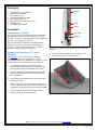
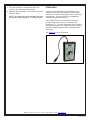
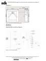
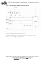
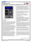
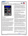
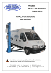
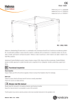
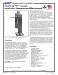
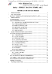
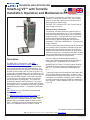
 TECHNICAL BULLETIN TB-6593 SmartLog V5™ with Turnstile
Installation, Operation and Maintenance
Made in the
United States of America and Britain
The turnstile is configured to Fail-Safe Loss-of-Power
Operation. Should loss of power occur, the turnstile’s
arms will unlock and rotate freely in both directions to
allow operators to pass through.
The EMIT 50777 SmartLog V5™ with Turnstile has an
input voltage of 220 VAC.
ESD Association Information
“Compliance verification should be performed prior to
each use (daily, shift change, etc.). The accumulation
of insulative materials may increase the foot grounder
system resistance. If foot grounders are worn outside
the ESD protected area testing for functionality
before reentry to the ESD protected area should be
considered.” ESD SP9.2 APPENDIX B - Foot Grounder
Usage Guidance
Figure 1. EMIT 50777 SmartLog V5™ with Turnstile
Description
The EMIT 50777 SmartLog V5™ with EDS
EDSUKTHH28 Half Height Turnstile verifies the
functionality of an operator’s wrist strap and footwear
and controls access to the ESD Protected Area. The
turnstile activates after the operator’s wrist strap and/or
footwear is determined to act as a path-to-ground. By
touching the solid-state switch once, the SmartLog V5™
independently tests the resistance path limits of both the
wrist strap and ESD footwear in less than 2 seconds.
It may also test a worn ESD garment if it is used as
part of personnel grounding path. Test results are
electronically stored in the SmartLog V5™ and easily
downloaded to a PC for logging records and evaluation.
This product can be used as one of the tools to fulfill the
ANSI/ESD S20.20 section 7.3 “Compliance Verification
Plan.”
“Process monitoring (measurements) shall be conducted
in accordance with a Compliance Verification Plan that
identifies the technical requirements to be verified, the
measurements limits and the frequency at which those
verifications shall occur...Compliance verification records
shall be established and maintained to provide evidence
of conformity to the technical requirements.
The test equipment selected shall be capable of
making the measurements defined in the Compliance
Verification Plan.” (ANSI/ESD S20.20) section 7.3
ANSI/ESD S20.20 Table 1 Flooring-Footwear Systems
Technical Requirements Recommended Range “less
than 3.5 x 10⁷ ohms measured per ANSI/ESD STM
97.1.”
“Typical test programs recommend that wrist straps that
are used daily should be tested daily. However, if the
products that are being produced are of such value that
knowledge of a continuous, reliable ground is needed,
and then continuous monitoring should be considered or
even required.” (ESD Handbook ESD TR 20.20 section
5.3.2.4.4)
See TB-6584 for more information on the patented*
EMIT SmartLog V5™.
The EDS EDSUKTHH28 Half Height Turnstile is a
bidirectional tripod swing turnstile. Both its cabinet and
tripod rotors are composed of stainless steel. LED
passage signs are located at both the entry and exit
sides. A flashing green arrow indicates when to pass,
and a red X indicates when the turnstile is closed.
*US Patents 6,078,875 and 6,809,522
EMIT - 3651 Walnut Avenue, Chino, CA 91710 • (909) 664-9980 • Website: DescoEMIT.com
TB-6593 Page 1 of 5
April 2015
© 2015 DESCO INDUSTRIES, INC.
Employee Owned
Packaging
1
1
1
1
2
2
2
1
Ground
SmartLog V5™ with Turnstile
Wall Mounting Bracket
Connection Cover
Dual Independent Foot Plate
Wall Mounting Anchors
Wall Mounting Screws, #10 x 1-1/2"
Turnstile Keys
Certificate of Calibration
Relay
Power
Installation
Installing the Turnstile
Foot Plate
A 220 VAC power line and Ethernet line are needed at
the installation location of every SmartLog V5™ with
Turnstile. Be sure to route these lines to the installation
site prior to anchoring your turnstile.
See the attached EDS Operation and Maintenance
Manual for instructions on anchoring and wiring the
turnstile. Do not use the SmartLog V5™ until the
turnstile is properly anchored and wired.
Installing the SmartLog V5™ to the
Turnstile
See TB-6584 to learn more about the features
and components of the SmartLog V5™. EMIT
recommends making any adjustments to its clock or test
configurations prior to deployment for operator use.
Ethernet
Figure 2. Connections to the SmartLog V5™ (right view,
cover off)
5. Align the slots on the back of the SmartLog V5™
with the hooks on the turnstile bracket.
1. Disconnect the SmartLog V5 tester from the
mounting bracket by removing the 4-40 pan head
screw located on the left-hand side of the tester.
2. Open the turnstile’s cover using the included keys.
Set the power switch located on the power box to
the ON position.
3. Route the Ethernet cable through the turnstile and
SmartLog bracket.
NOTE: Cat5e cable is recommended for Ethernet
wiring. Cat6 cable may prove to be too rigid for most
installations inside the SmartLog’s mounting bracket.
4. Follow Figure 3 to learn where to connect the
Ethernet cable on the SmartLog V5™.
Figure 3. Locating the mounting hooks on the bracket
EMIT - 3651 Walnut Avenue, Chino, CA 91710 • (909) 664-9980 • Website: DescoEMIT.com
TB-6593 Page 2 of 5
© 2015 DESCO INDUSTRIES, INC.
Employee Owned
6. Slide the SmartLog V5™ into the bracket from the
top to bottom. Secure the SmartLog V5™ to the
bracket by fastening the 4-40 screw to the left side of
the tester.
slide down
Operation
NOTE: The SmartLog V5™ must first be programmed
with the user ID table using the TEAM5 Software before
being deployed for employee use, or the default test
settings will be applied.
See the TEAM5 User Manual for more information.
1.
Initiate the test procedure by identifying yourself to
the SmartLog. This may be done using the keypad,
barcode badge scanner or proximity badge reader (if
supplied).
2. Follow the prompt on the SmartLog’s display.
Figure 4. Sliding the SmartLog V5™ into the bracket and
securing it into place with the 4-40 screw
7. Locate the foot plate cable at the base of the
turnstile and connect it to the Dual Independent
Foot Plate. Place the foot plate at the base of the
turnstile so operators can place their feet on it while
performing tests at the turnstile’s entrance.
3. When performing a footwear test, be sure to place
both feet on the dual foot plate (one foot per plate).
When performing a wrist strap test, be sure to
completely plug in the wrist cord into the tester’s
jack.
4. Press and hold the metal touch plate on the tester
to perform the test. Hold your finger on the touch
plate until the results of the test are displayed.
If performing a wrist strap test, and the wrist strap
status LEDs do not illuminate, verify that the wrist
cord is correctly inserted into the tester.
Figure 5. Installing the Dual Independent Foot Plate
8. Complete the installation by establishing
communication to the SmartLog V5 via the Ethernet
cable. See the “Ethernet Setup” procedure in TB6584 for more information.
Figure 6. Using the SmartLog V5™ with Turnstile
EMIT - 3651 Walnut Avenue, Chino, CA 91710 • (909) 664-9980 • Website: DescoEMIT.com
TB-6593 Page 3 of 5
© 2015 DESCO INDUSTRIES, INC.
Employee Owned
5. The relay terminal will activate and unlock the
turnstile if the defined tests are passed.
Calibration
6. Pass through the turnstile. The turnstile will re-lock
after one rotation.
Frequency of recalibration should be based on the
critical nature of those ESD sensitive items handled
and the risk of failure for the ESD protective equipment
and materials. In general, EMIT recommends that
calibration be performed annually.
NOTE: The turnstile will remain unlocked until either
the operator passes through or 15 seconds expire.
Use the EMIT 50424 Limit Comparator to perform
periodic testing (once every 6-12 months) of the
SmartLog V5™. The Limit Comparator can be used on
the shop floor within a few minutes virtually eliminating
downtime, verifying that the tester is operating within
tolerances.
See TB-6581 for more information.
Figure 7. EMIT 50424 Limit Comparator
EMIT - 3651 Walnut Avenue, Chino, CA 91710 • (909) 664-9980 • Website: DescoEMIT.com
TB-6593 Page 4 of 5
© 2015 DESCO INDUSTRIES, INC.
Employee Owned
Specifications
SMARTLOG V5™ WITH TURNSTILE
Operating Voltage
220 VAC, 50/60 Hz
SMARTLOG V5™ TESTER
Operating Voltage
100-240 VAC, 50/60 Hz
Operating Temperature
0 to 40°C (32°F to 104°F)
Operating Temperature
32°F to 104°F (0 to 40°C)
Dimensions (Crated)
47" x 31" x 54"
(119cm x 78cm x 137cm)
Dimensions 8.3" x 5.8" x 1.9"
(21.1cm x 14.7cm x 4.8cm)
Dimensions (Uncrated)
See Figure 8
Weight
2.0 lbs (0.9 kg)
Weight (Crated)
257 lbs (116.4 kg)
Weight (Uncrated)
135 lbs (61.4 kg)
DUAL INDEPENDENT FOOT PLATE
Dimensions 14.0" x 16.0" x 0.9"
(35.6cm x 40.1cm x 2.3cm)
Weight
7.5 lbs (3.4 kg)
TURNSTILE CERTIFICATIONS
• CE
Certificates are available upon request to EMIT Customer
Service.
27.6"
(70 cm)
33.3"
(85 cm)
37.4"
(95 cm)
47.1"
(120 cm)
41.3"
(105 cm)
11.0"
(28 cm)
Figure 8. Dimensions of the EMIT 50777 SmartLog V5™ Turnstile
Limited Warranty, Warranty Exclusions, Limit of Liability and RMA Request Instructions
See EMIT’s Warranty http://emit.descoindustries.com/Warranty.aspx
EMIT - 3651 Walnut Avenue, Chino, CA 91710 • (909) 664-9980 • Website: DescoEMIT.com
TB-6593 Page 5 of 5
© 2015 DESCO INDUSTRIES, INC.
Employee Owned
EDSUKTHH28 Half Height Turnstile Operation and Maintenance Manual
EDSUKTHH28
Turnstile
Operation and Maintenance Manual
EDSUK reserves the right to make changes at any time without any notice. All rights reserved. Page 1 of 16
© Copyright EDS (Electrical-Data-Security) Ltd The Service Provider
www.edsuk.com Tel. 0870 735 5050 Fax 0870 735 5533
EDSUKTHH28 Half Height Turnstile Operation and Maintenance Manual
Before You Start
3
EDSUKTHH28 Turnstile System Technical Specifications
5
Dimensions:
6
Modules
6
EDSUKTHH28_A Turnstile Block Diagram:
7
BM32 Turnstile control module:
7
Keypad:
7
Programming:
8
Input and Output Ports:
9
BM 29 Indicator Cards
12
Other Equipments
13
Turnstile Electrical Circuit Diagram:
13
EDSUKTHH28 Turnstile Mechanic Mounting Instructions
13
Mounting Drawing for EDSUKTHH28
13
EDSUKTHH28 Material List
13
EDSUKTHH28 Turnstile Maintenance Instructions
14
Turnstile Troubleshooting
14
EDSUK reserves the right to make changes at any time without any notice. All rights reserved. Page 2 of 16
© Copyright EDS (Electrical-Data-Security) Ltd The Service Provider
www.edsuk.com Tel. 0870 735 5050 Fax 0870 735 5533
EDSUKTHH28 Half Height Turnstile Operation and Maintenance Manual
Before You Start
Thank you for purchasing EDSUKTHH28 Electro-mechanic Turnstile.
Please, carefully read the instructions contained in this manual and
keep the manual for future references.
TURNSTILE SAFETY INSTRUCTIONS
•
•
•
•
•
•
It is recommended to read all safety and maintenance instructions before
installing and using the turnstile.
Read the manual, before operating the turnstile.
Do not open the turnstile, due to safety precautions.
Any repairs must be done by authorized services only. Modifications made by user
may result in danger for the turnstile and people.
Do not operate damaged turnstiles and call an authorized service immediately.
Comply with the power and voltage values specified in the technical
specifications of turnstile.
•
Comply with the operating temperature range specified in the technical
specifications of turnstile.
•
Check the power supply and control the card connections before re-energizing
the turnstile afterwards any maintenance or damage.
Use certificated spare parts and accessories approved by EDSUK.
If any problem, switch off the electrical connections of the turnstile and call
EDSUK
•
•
•
•
•
•
•
During the cleaning and maintenance, cut off the electrical connections.
Otherwise damage to the parts may result.
Use wet rag for cleaning.
Keep the turnstile away from over heated or fire environment. Over heat may
result in a damage to the turnstile.
Do not use the turnstile in high magnetic areas.
Do not expose the turnstile to excessive water in order to prevent any
penetration.
EDSUK reserves the right to make changes at any time without any notice. All rights reserved. Page 3 of 16
© Copyright EDS (Electrical-Data-Security) Ltd The Service Provider
www.edsuk.com Tel. 0870 735 5050 Fax 0870 735 5533
EDSUKTHH28 Half Height Turnstile Operation and Maintenance Manual
TURNSTILE USAGE INSTRUCTIONS
•
•
•
•
•
The turnstile is designed so as to allow one person to pass each time
and more than one person mustn’t try to pass at the same time.
In case of not functioning properly, avoid actions that may result in
damage to the turnstile.
In case of any malfunctioning and in order to avoid further damage,
T he system should be switched off and not used.
Substances harmful to turnstile mustn’t be used for cleaning.
The manufacturer will not accept any responsibility for any inquiry or
damage resulting from incompliance with the security and safety
instructions indicated above.
EDSUK reserves the right to make changes at any time without any notice. All rights reserved. Page 4 of 16
© Copyright EDS (Electrical-Data-Security) Ltd The Service Provider
www.edsuk.com Tel. 0870 735 5050 Fax 0870 735 5533
EDSUKTHH28 Half Height Turnstile Operation and Maintenance Manual
EDSUKTHH28 Turnstile System Technical Specifications
Power - 220 V AC or 24 V DC 30W
Operating Voltage - 24 V DC +- %20
Operating Temp -20 C0 - + 70 C0
Dimensions - 280x950x1050 mm Weight 75 kg
Body Features - Waterproof body with 1.5mm 304 grade stainless steel
Outdoor Use - Turnstiles are designed for outdoor use.
Tripod Block - With controlled tripod arms positioned with at 1200 degrees
Arms - Polished stainless pipe, Ø32x2mm. Each arm can be demounted.
Tripod Lock - It is locked with 24DC solenoids, locks when the solenoids are pulled. In
emergency, the system is shut down and turnstiles provide free passing in both
directions.
Motion Control - When the cycle starts to one direction, the reverse is blocked and after a
half turn the rest of the cycle is completed, automatically and smoothly by a hydraulic
shock absorber.
Optional Accessories Electronic control unit, Remote unit, Button unit, Modular Platform
Control - It is commanded by TTL, CMOS, and Dry Contact for pass triggering.
Additionally, it can be commanded by RS 232, RS422, and RS485 through PC with BM33
module. It is possible to command additional warning/caution devices that can be
mounted on Turnstile through 3 extra dry contact relays when used with BM33 module. It
is possible to use with all kinds of Access control units.
System - Micro Controller was designed based on Modular structure. Turnstile is a
combination of the modules that fit for your requirements. Thereby, in comparison with
complicated systems, it eliminates the additional costs to be paid for the modules you do
not require as well as avoiding the defects from the parts which do not belong to system
and the extra power consumption used by them. When used with PC, if required, it is
possible to follow how many passes were made through the turnstile. It was designed so as
to operate bidirectional. If required, it can be transformed so as to operate bidirectional or
to a free turnstile (only with setting).
Emergency Mode - When the power supply of the turnstile is cut, passing becomes free in
both directions. When the free button is pressed, passing becomes free in both directions.
In models with retractable arms, when the panic button is pressed, arms drop down
automatically and passageway is opened entirely.
Passage Signs - There are indicators with two-colored lights on both sides at entry and exit.
Indicators - On stand by state, it indicates that the turnstile is ready with continuous
"green arrow". Flashing green arrow in passing direction indicates free passing and
continuous red “X” sign in opposite direction indicates that passing though the opposite
direction is opened and waiting is required. An audio alarm indicates that passing is
opened at the time of passing. Audio alarm will accelerate and indicate lapse of time
close to end of the time given for passing.
Quality System - Manufacture process of our turnstiles is assured under ISO-9001-2000
quality system. Compliance with relevant EN, DIN and TSE standards are based on for all
kinds of product used in production.
EDSUK reserves the right to make changes at any time without any notice. All rights reserved. Page 5 of 16
© Copyright EDS (Electrical-Data-Security) Ltd The Service Provider
www.edsuk.com Tel. 0870 735 5050 Fax 0870 735 5533
EDSUKTHH28 Half Height Turnstile Operation and Maintenance Manual
Dimensions:
Figure 1. Dimensions of EDSUKTHH28 Turnstile
Modules
EDSUKTHH28 Turnstile Block Diagram:
Figure 2. Turnstile Block Diagram
EDSUK reserves the right to make changes at any time without any notice. All rights reserved. Page 6 of 16
© Copyright EDS (Electrical-Data-Security) Ltd The Service Provider
www.edsuk.com Tel. 0870 735 5050 Fax 0870 735 5533
EDSUKTHH28 Half Height Turnstile Operation and Maintenance Manual
BM32 Turnstile control module:
Manufactured with reliable 8051 micro-controller technology, it has
two main modes as operating and programming. Operating mode can
be programmed according to the list below.
Keypad:
Input, output and mode keys are available on BM 32 card.
Programming mode or operating mode can be selected by the mode
key. Input and output keys provide entry and exit right while the
turnstile is in “Operating mode”.
In programming mode, it is used for adjustment of turnstile as indicated
the table above.
Figure 3. BM32 Card Connectors, Cable Colors, and Keypad
Operating Mode
Input
Output
Required key combination for programming
Press M and simultaneously press G or C until
0
Locked
Locked
input and output displays turn to red (until
LD14 and LD15 LEDs are turned off)
The following modes are written assuming that the operating mode of the turnstile is 0.
Controlled
Controlled
1
M+G+G+C+C+M
Passing
Passing
Controlled
2
Locked
M+C+C+M
Passing
Controlled
3
Locked
M+G+G+M
Passing
Controlled
4
Free
M+G+C+C+M
Passing
Controlled
5
Free
M+G+G+C+M
Passing
6
Locked
Free
M+C+M
7
Free
Locked
M+G+M
9
Free
Free
M+G+C+M
EDSUK reserves the right to make changes at any time without any notice. All rights reserved. Page 7 of 16
© Copyright EDS (Electrical-Data-Security) Ltd The Service Provider
www.edsuk.com Tel. 0870 735 5050 Fax 0870 735 5533
EDSUKTHH28 Half Height Turnstile Operation and Maintenance Manual
Programming:
For entering and exiting to programming mode, Mode Key
is used. In Programming Mode:
• Entry key changes the passing right among “Free”, “Controlled passing” and
“Locked”, respectively.
• Exit key, changes the passing right among “Free”, “Controlled passing” and
“Locked” respectively.
• In “Free” state, indicator is green, and no buzzer audio.
• “Controlled Passing” state, indicator is green and buzzer alarms.
• In “Locked” state the indicator is red.
• Use mode Key to exit from programming mode.
When not in programming mode:
• Entry key gives entry right,
• Exit key gives exit right.
Input and Output Ports:
+24 VDC supply:
It connects via J1 connector. All voltage levels necessary for circuit is
obtained from this source.
Token Signal and Token Counter Ports:
Token mechanism connects via J2 connector. J2 provides 12 V supply
voltage required for Token mechanism. The “Token was dropped” signal
which is produced by the mechanism is taken from this connector.
Figure 4. Token Mechanism and Token Counter Connection Equivalent Circuit
It produces one “passing right to entry side” signal in return for “token
was dropped” signal and the signal required for increasing the value
on the token counter by one level.
Avoid drawing current more than 0 mA instantly and 100 mA continuously
from the
J3.2 JSA connector.
EDSUK reserves the right to make changes at any time without any notice. All rights reserved. Page 8 of 16
© Copyright EDS (Electrical-Data-Security) Ltd The Service Provider
www.edsuk.com Tel. 0870 735 5050 Fax 0870 735 5533
EDSUKTHH28 Half Height Turnstile Operation and Maintenance Manual
“Free”, “Authorize entry” and “Authorize exit” Inputs:
Figure 5. Input Output and Free Ports Equivalent Circuit
As indicated in the diagram, turning the ports to low position or to GND
by dry contact is enough to trigger the input.
EDSUK reserves the right to make changes at any time without any notice. All rights reserved. Page 9 of 16
© Copyright EDS (Electrical-Data-Security) Ltd The Service Provider
www.edsuk.com Tel. 0870 735 5050 Fax 0870 735 5533
EDSUKTHH28 Half Height Turnstile Operation and Maintenance Manual
Home and Turn Microswitch Inputs:
Figure 6. Home and Turn Microswitches Connection Equivalent Circuit
NO contacts of the Microswitches on the mechanism are connected via BM 32
card’s
TurnMS and HomeMS inputs.
EDSUK reserves the right to make changes at any time without any notice. All rights reserved. Page 10 of 16
© Copyright EDS (Electrical-Data-Security) Ltd The Service Provider
www.edsuk.com Tel. 0870 735 5050 Fax 0870 735 5533
EDSUKTHH28 Half Height Turnstile Operation and Maintenance Manual
“Passing Counter”, “Audio” and “Indicator” Control Outputs:
Figure 7. Passing Counter, Audio and Indicator Ports Equivalent Circuit
Passing counter, audio, and indicators are open collector type outputs.
“Solenoid” Control Outputs:
Figure 8. Solenoid Ports Equivalent Circuit
Solenoid outputs are dry contact and normally in open relay type.
EDSUK reserves the right to make changes at any time without any notice. All rights reserved. Page 11 of 16
© Copyright EDS (Electrical-Data-Security) Ltd The Service Provider
www.edsuk.com Tel. 0870 735 5050 Fax 0870 735 5533
EDSUKTHH28 Half Height Turnstile Operation and Maintenance Manual
BM 29 Indicator Cards
Connector includes 24 V Supply pin, GND pin, and Signal pin. The green
allow or red allow flashes according to the information coming from the
Signal pin under power supply.
Figure 9. BM29 Equivalent Diagram
Other Equipments
Solenoids
In T-Mek A models, Solenoids draw 300 mA continuous (Constant) current with 24 V supply.
In T-Mek B models Solenoids draw 1500 mA continuous (constant) current with 24 V supply.
Counters:
24 V Mechanic or Electronic Counter can be used.
Power Supply:
Model Mean Well trade mark 25 W, 24V, S-25-24 power supply is used.
On the right: The Picture of the power supply
EDSUK reserves the right to make changes at any time without any notice. All rights reserved. Page 12 of 16
© Copyright EDS (Electrical-Data-Security) Ltd The Service Provider
www.edsuk.com Tel. 0870 735 5050 Fax 0870 735 5533
EDSUKTHH28 Half Height Turnstile Operation and Maintenance Manual
Heating and Air Circulation Circuit:
For air circulation 90-90 fan is used. It operates when the temperature of
the turnstile heated over 35 °C. For heating, 200 W heater is used. When
the internal temperature of turnstile is below 10°C, it starts to operate
automatically with fan. The heating and air circulation circuits can be set by
thermostat, it can be set to different degrees depends on demand.
Fuse: - Protected by 2 A automatic fuse.
Turnstile Electrical Circuit Diagram:
Figure 10. Circuit Diagram
EDSUKTHH28 Turnstile Mechanic Mounting Instructions
1. Select a proper location so as not to obstruct turnstile’s operation.
2. Check the structure of the ground of installation site to ensure the
necessary stability requirements.
3. Mark the hole places on the ground in which the turnstile will be mounted.
4. Drill the marked mounting holes by Ø10 drill bit and clean the dust
inside the hole by the help of the air.
5. Fix the steel anchors to the drilled holes. If the ground is not strong, fix
the steel anchors after using chemical soil mixture. (Wait 20 minutes for
hardening of chemical soil mixture)
6. Pass the power and data cables which are prepared before through the
hole on mounting plate.
7. Put the mounting plate on the steel anchors and after putting the
washer and nuts, fix the ground.
8. After putting the turnstile on the fixed mounting frames, screw
the bolts connecting the turnstile and mounting plate to each
other.
EDSUK reserves the right to make changes at any time without any notice. All rights reserved. Page 13 of 16
© Copyright EDS (Electrical-Data-Security) Ltd The Service Provider
www.edsuk.com Tel. 0870 735 5050 Fax 0870 735 5533
EDSUKTHH28 Half Height Turnstile Operation and Maintenance Manual
Mounting Drawing for EDSUKTHH28
Figure 11. Mounting Drawing for EDSUKTHH28
EDSUKTHH28 Material List
M10x85 Steel Anchor
M10x20 Inbus Bolt
M10 Washer
4 pieces
4 pieces
4 pieces
EDSUKTHH28 Turnstile Maintenance Instructions
1. The clothing of the turnstile must be cleaned with wet rag.
2. The connection screws of turnstile should be visually checked every 6
months.
3. Turnstile arm connection must be visually checked.
NOTE: Turnstile must have maintenance service by authorized service or
distributors periodically. In case it is not able to contact with an authorized
service or dealer, get into contact with producer firm and obtain information
on periodical maintenance.
EDSUKTHH28 Electro mechanic Turnstile
General
Operation
Turnstile Arm Torque Bolt
12 months
Control
Ground Fixing Bolts
12 months
Control
Control + Cleaning
Springs
12 months
12 months
Control
Hydraulic Shock Absorber
12 months
Control
Hydraulic Shock Absorber
36 months
Renewing the oil
Mechanism Connection Cable
12 months
Control
Components
Electrical Connections
12 months
12 months
Control + Lubrication
Control
Indicator Cards
12 months
Control + Cleaning
Electronic Cards
12 months
Control
Turnstile Mechanism Solenoids
Electronic Card
Time
EDSUK reserves the right to make changes at any time without any notice. All rights reserved. Page 14 of 16
© Copyright EDS (Electrical-Data-Security) Ltd The Service Provider
www.edsuk.com Tel. 0870 735 5050 Fax 0870 735 5533
EDSUKTHH28 Half Height Turnstile Operation and Maintenance Manual
Turnstile Troubleshooting
Fault
Reasons
Electricity is on, the arms
cannot be locked, the displays
are turned off, and the
turnstile is functionless.
1.Power supply may be off
or broken.
After one pass, the turnstile is
not locked and it allows
multiple passes.
2.Electrical fuse could be
blown out.
Solution
1. Check whether the electrical
cable is plugged in.
2. Change power supply if needed.
1.Direction sensor micro
1.Replace micro switches.
switches could be broken.
2. Replace electronic card.
2.Electronic card could be
Although indicators and buzzer
work, the turnstile does not
allow pass.
Electricity is on the arms are
turning freely.
broken.
1.There may be a cable
preventing the solenoid to
open.
2. Electronic card could be
broken.
3. Solenoid could be
broken or there may be
connection defects.
1. The problematic cable is
fixed.
2. Replace electronic card.
3. Replace solenoid and also
check the connections.
1. Replace solenoid and also
1.Solenoid could be broken check the connections.
or there may be
2. Replace electronic card.
connection defects.
2.Electronic card could be
broken.
The turnstile does not send info
after pass.
1.Cycle sensor micro
switches could be broken
or there may be
1.Replace microswitches and
check the connections.
2.Ckeck the cables carrying
data.
3. Replace
electronic card.
connection defects. 2.
There may be defects in
the cable transferring
data. 3.Electronic card
Turnstile arms are giving noise
due to friction while turning.
could be broken.
The oil within the rotor
wheels could be dirty or
runs out.
Lubricate the rotor wheels.
In winter or summer turnstiles
do not operate smoothly.
Due to the changes in
Choose the wanted calibration
smoothness using the cap screw
behind the dumper.
temperature, the damper
oil may not work properly.
EDSUK reserves the right to make changes at any time without any notice. All rights reserved. Page 15 of 16
© Copyright EDS (Electrical-Data-Security) Ltd The Service Provider
www.edsuk.com Tel. 0870 735 5050 Fax 0870 735 5533
EDSUKTHH28 Half Height Turnstile Operation and Maintenance Manual
Arms remain crosswise after pass
1.The spring in the
1.The spring is adjusted or
and they do not return to initial
mechanism may be loosen
replaced.
position.
up.
2. Hydraulic damper setting is
2.Hydraulic damper or its
adjusted with the help of the cap
calibration may be at
screw behind the dumper or
fault.
replaced.
Although the pass signal is given,
1.There may be problems
1.Replace the signal sender and
the turnstile does not allow
in the signal sender (card
check the connections.
passing.
reader, remote control,
button) or its connections.
2. Electronic card could be
2. Replace electronic card.
broken.
3.Solenoid could be
3.Replace the solenoid.
broken.
4.Lock pins could
malfunction.
The turnstile allows multiple
1.Solenoid could be broken 1.Replace the solenoid and check
passes continuously.
or its cables may be
the cables.
unplugged.
2.Lock pins could
2.Set the turnstile to the wanted
malfunction.
Mode.
3. The turnstile could be
set to free Mode to
operate in one direction.
EDSUK reserves the right to make changes at any time without any notice. All rights reserved. Page 16 of 16
© Copyright EDS (Electrical-Data-Security) Ltd The Service Provider
www.edsuk.com Tel. 0870 735 5050 Fax 0870 735 5533