1
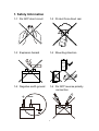
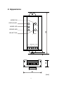
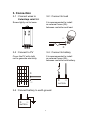
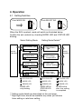
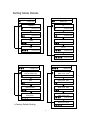
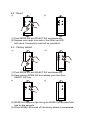
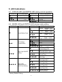
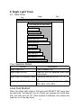
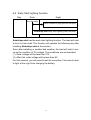
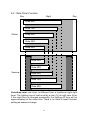
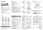
Solar Charge Controller SA-MN05 User's Manual Ver. 2.10E RoHS DENRYO CO., LTD. Contents 1. Safety Information............................................................................ 3 2. Appearance...................................................................................... 4 3. Connection....................................................................................... 5 4. Operation......................................................................................... 6 5. LED Indications................................................................................ 9 6. Night Light Timer.............................................................................. 10 7. Troubleshooting................................................................................13 8. Specifications................................................................................... 14 9. Certifications.................................................................................... 14 10. Glossary........................................................................................... 15 Thank you for purchasing the SolarAmp mini solar charge controller. This manual contains important safety, installation and operating instructions for the SolarAmp mini solar charge controller in order to prevent the users from any damage. Make sure to read all of the instructions and cautions in the manual before beginning installation. 2 1. Safety Information 1-1 : Do NOT short circuit 1-2 : Protect from direct rain 1-3 : Explosion hazard 1-4 : Mounting direction 1-5 : Negative earth ground + 1-6 : Do NOT reverse polarity connection − − + 3 + − 2. Appearance MODE SW STATUS LED STATUS MODE SW MODE LED MODE ERROR LED ERROR 120 SELECT SW SELECT SW RESET PV BATTERY LOAD + − + − + − 20 5 20 50 (mm) 4 3. Connection 3-1 : Connect wires to SolarAmp mini first 3-2 : Connect to load Screw tightly not to loose. It is recommended to install an external fuses (5A) between controller and load. − + 3-3 : Connect to PV 3-4 : Connect to battery Cover the PV with cloth not to generate electricity. It is recommended to install an external fuses (5A) between controller and battery. + + − 3-5 : Connect battery to earth ground + − BATTERY − BATTERY 5 4. Operation 4-1 : Setting Switches Push MODE SW Push SELECT SW When the SW is pushed, mode will switch as illustrated below. Confirm the set contents by checking MODE LED and STATUS LED blinking. Setting Mode Details*1 Select Setting Mode Select Battery Type (1) Select Battery Type MODE LED Normal Operation Normal Operation LVD Voltage Compensation (2) LVD Voltage Compensation MODE LED Night Light ON/OFF Setting (3) Night Light ON/OFF Setting MODE LED Night Light 2 Timer Setting * (4) Night Light Timer Setting MODE LED STATUS LED STATUS LED STATUS LED MODE LED MODE LED MODE LED ERROR LED ERROR LED MODE LED only blinking. MODE LED & STATUS LED blinking. ERROR LED All LEDs blink after the setting is completed. *1 Setting mode details are described on the next page. *2 Night light timer should be available only when you choose timer setting or rate timer setting. 6 Setting Mode Details (1) Select Battery Type (2) LVD Voltage Compensation MODE LED Sealed MODE LED * 0V STATUS LED * STATUS LED Flooded -0.1V STATUS LED STATUS LED -0.2V AGM STATUS LED STATUS LED +0.1V Gel STATUS LED STATUS LED +0.2V STATUS LED (3) Night Light ON/OFF Setting (4) Night Light Timer Setting MODE LED MODE LED * Normal Timer 6h * Rate Timer 40% * Night Light OFF Load is always ON. STATUS LED STATUS LED Night Light ON D/D Normal Timer 8h Rate Timer 50% STATUS LED STATUS LED Normal Timer 10h Rate Timer 60% Night Light ON Normal Timer STATUS LED STATUS LED Normal Timer 12h Rate Timer 70% Night Light ON Rate Timer STATUS LED STATUS LED * Normal Timer 14h Rate Timer 80% Factory Default Setting STATUS LED 7 4-2 : Reset (1) (2) (1) Push MODE SW and SELECT SW simultaneously. (2) Release your hands from both of the SWs than LED (2) blink twice. Successfully reset will be completed. 4-3 : Factory default (1) (2) (1) Push MODE SW and SELECT SW simultaneously. (2) Keep pushing MODE SW and release your hand from (2) SELECT SW only. (3) (4) (3) MODE LED keeps to light during the MODE SW is pushed and (3) hold for five seconds. (4) When MODE LED turned off, the factory default is compeleted. 8 5. LED Indications 5-1 : STATUS LED and ERROR LED during normal operation STATUS LED STATUS Descriptions ERROR LED ERROR Descriptions LVD (LOAD OFF) Battery Level Low Middle Battery Error Full PV Error LVD & PV Error 5-2 : MODE LED and STATUS LED during mode setting MODE LED MODE Description STATUS LED Select Battery Type STATUS Description Sealed * : Charging 14.1V Float 13.7V Flooded : Charging 14.4V Float 13.7V AGM : Charging 14.3V Float 13.3V Gel : Charging 14.3V Float 13.7V 0V* -0.1V -0.2V +0.1V +0.2V Night Light OFF* Load is always ON Night Light ON D/D(Load ON All night) LVD Voltage Compensation Night Light ON/OFF Setting Night Light ON Normal Timer Night Light ON Rate Timer Normal Timer 6h * Rate Timer 40% * Normal Timer 8h Rate Timer 50% Normal Timer 10h Rate Timer 60% Night Light Normal Timer or Rate Timer Setting Normal Timer 12h Rate Timer 70% Normal Timer 14h Rate Timer 80% *Factory Default Setting 9 6. Night Light Timer 6-1 : Multi Timer Night Day Day Night Light OFF (Load is always ON) D/D Load ON (All night timer) Normal Timer 6h Normal Timer 8h Normal Timer 10h Normal Timer 12h Normal Timer 14h Rate Timer 40% Rate Timer 50% Rate Timer 60% Rate Timer 70% Rate Timer 80% Four Operation Modes MODE Night Light OFF Night Light ON D/D Description Load is always ON. Load will turn on between dusk time and sunrise. Night Light ON Normal Timer Customize setting hours 6, 8, 10, 12, 14. Night Light ON Rate Timer Choose the rate of night time 40%, 50%, 60%, 70%, 80%. Load Test Method When the Night light mode is ON and push SELECT SW more than two seconds, the load will turn on. When you release your hand from SW, the load will turn off. (This method is effective only before the load turn on in the day time). 10 6-2 : Early Start Lighting Function Day Night Dusk Turn on early Other controller's night light load ON point SolarAmp mini early start lighting load ON point SolarAmp mini has the early start lighting function. The load will start to turn on from dusk. This function will operate the following day after insatlling SolarAmp mini at the earliest. Soon after installing or sudden bad weather, the load will start to turn on by the condition of PV voltage. The conditions are as described. (1) Solar voltage will be less than 10V. (2) After that, solar voltage will be less than 8V. For this reasons, you will need to wait for more than 3 minutes to start to light at the night from charging the battery. 11 6-3 : Rate Timer Function Day Night Day Rate 80% Rate 70% Winter Rate 60% Rate 50% Rate 40% Rate 40% Rate 50% Summer Rate 60% Rate 70% Rate 80% SolarAmp mini rate timer is different from a traditional night-light timer. The lighting time of load is set by a rate (%) of night time. Even if the night time is changed seasonally, the lighting-off time will be apporoximately at the same time. There is no need to reset the timer setting as seasons change. 12 7. Troubleshooting 7-1 : Lighting ERROR LED LVD : The battery voltage is low. Please charge with the battery 12.5V or more until becoming it. Battery : The cause is as follows. • Battery is not connected • Battery is low or too high voltage • Short-circuited • Deeply discharged battery cannot charge with recovery Please check the wire connection and battery voltage for the system. PV : The PV voltage is lower than battery voltage. This error will remain for about one minute after PV begins to generate. There is no problem though this error occurs during the night. LVD&PV : LVD and the PV error occur at the same time. 7-2 : Battery is not charged SolarAmp mini charge controller will not charge unless the PV voltage is higher than battery voltage. It takes approximately 3 minutes to start charging from PV voltage. In the event of a battery fault the charge controller will not charge. On the other hand, the charge controller will not charge when battery is fully charged or battery voltage more than 13V. 7-3 : Load does not operating properly Please check LVD status of solar controller. Even If the battery voltage is over 11.5V, once the controller become LVD, the load will NOT turn on unless the battery voltage be over 12.5V. 7-4 : LED does not light SolarAmp mini automatically turns off LED. LED lights for one minute only when SELECT SW is pushed. 7-5 : Early start lighting function does not operate The Early start lighting function does not operate on that day when the installation first day and the setting were changed. Besides, when it gets dark suddenly by the bad weather, it begins to light detecting from the power generation of the solar battery as well as an usual controller. 13 8. Specifications Model System Voltage Max. input Voltage Max. input Current Max. load Current Min. input battery Voltage Grounding Self-consumption Current Reverse Polarity Protected Operation Temperature Storage Temperature Humidity Dimensions (D x W x H) Weight Wire Size Battery Type Charging Voltage Load Disconnect Voltage LVD Reconnect Charging Algorithm Temperature Coefficient SA-MN05 12 V 25 V 5A 5A 6V Negative ground 1 mA Fuse:10 A - 20 〜 + 60 ℃ - 30 〜 + 70 ℃ 5 〜 95 %RH (non-condensing) 20 x 50 x 120 mm 105 g 16AWG (1.3 mm2) 〜 22AWG (0.33 mm2) Sealed, Flooded, AGM, Gel Sealed Battery:14.1 V Flooded Battery:14.4 V AGM Battery:14.3 V Gel Battery:14.0 V 11.5 V (±0.2 V) 12.5 V (±0.2 V) 3-stage (Bulk, Absorption, Float) -30 mV/℃ 9. Certifications RoHS 14 10. Glossary PV : Photovoltaics Module (Solar Panel) LVD : Low Voltage Disconnect D/D : Dusk to Dawn This Document must not be copied, photocopied, reproduced or converted to any electronic or machine-readable form in whole or in part without prior written approval of DENRYO CO., LTD. © 2010-2012 DENRYO CO., LTD. All Rights Reserved. DENRYO CO., LTD. 28-5, Nishinippori 2 Chome, Arakawa-ku Tokyo, 116-0013 Japan TEL FAX Email Website : : : : +81-3-3802-3671 +81-3-3802-2974 [email protected] www.denryo.com 15 DD1M-0231