1
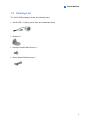
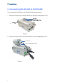
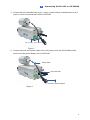
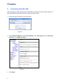
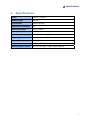
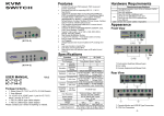
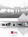
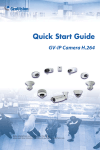
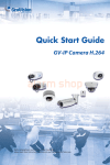
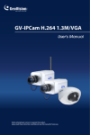
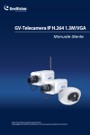
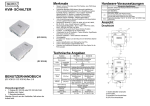
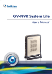
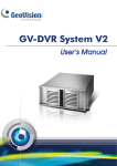
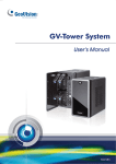
GV-IR LED
User's Manual
Before attempting to connect or operate this product,
please read these instructions carefully and save this manual for future use.
© 2010 GeoVision, Inc. All rights reserved.
Under the copyright laws, this manual may not be copied, in whole or in part,
without the written consent of GeoVision.
Every effort has been made to ensure that the information in this manual is
accurate. GeoVision is not responsible for printing or clerical errors.
GeoVision, Inc.
9F, No. 246, Sec. 1, Neihu Rd.,
Neihu District, Taipei, Taiwan
Tel: +886-2-8797-8377
Fax: +886-2-8797-8335
http://www.geovision.com.tw
Trademarks used in this manual: GeoVision, the GeoVision logo and GV
series products are trademarks of GeoVision, Inc. Windows and Windows XP
are registered trademarks of Microsoft Corporation.
March 2010
Contents
Preface ...................................................................................................................... 1
1. Introduction..............................................................................................2
1.1
Features...................................................................................................... 2
1.2
Packing List................................................................................................. 3
2. Connecting GV-IR LED to GV-IPCAM .....................................................4
3. Installing GV-IR LED ................................................................................6
4. Specifications ..........................................................................................7
Preface
Welcome to the GV-IR LED User’s Manual.
The GV-IR LED is an indoor-use infrared illuminator, which is designed to work with
the GV-IPCAM for a better night vision. The GV-IR LED can only be compatible with
the GV-IPCAM supporting wet-contact input devices. The tables below list the
compatible and incompatible models of GV-IPCAM.
Compatible GV-IPCAM models (with wet-contact support)
Model No.
Description
GV-BX110D
GV-IPCAM, 1.3 M, H.264, D/N
GV-BX010D
GV-IPCAM, VGA, H.264, D/N
Incompatible GV-IPCAM models (with dry-contact support)
Model No.
Description
81-13MBC-C01
GV-IPCAM, 1.3M, Box
81-13MBC-D01
GV-IPCAM, 1.3M, Box
81-13MVC-C01
GV-IPCAM, 1.3M, Varifocal
81-13MVC-D01
GV-IPCAM, 1.3M, Varifocal
81-13MVD-C01
GV-IPCAM, 1.3M, Vandal Proof Dome
81-13MVD-D01
GV-IPCAM, 1.3M, Vandal Proof Dome
1
1.
Introduction
The GV-IR LED is designed to automatically detect the illumination of the environment and
determine it to be day mode or night mode. It is also designed to work perfectly with the
GV-IPCAM to improve the image performance in low-light or night situations.
Featured with the D/N auto detection function, the GV-IR LED is able to control the IR Cut
Filter built in the GV-IPCAM through input trigger signals. In night mode of 10 lux or lesser
illuminance, the infrared light of GV-IR LED will turn on and the camera images will be
switched to monochrome to produce better images. In day mode of 20 lux or higher
illuminance, the infrared light of GV-IR LED will turn off and the camera images will be
switched to color. Following is the comparison of the GV-IPCAM working with and without the
GV-IR LED in 10 lux illuminance.
With GV-IR LED
Without GV-IR LED
1.1 Features
• Indoor infrared illumination
• 850 nm LEDs
• 12 IR LEDs for 10-meter illumination distance
• D/N mode auto detection
• 12V DC power supplied from GV-IPCAM. No separate power adapter is required.
2
1
Introduction
1.2 Packing List
The GV-IR LED package includes the following items:
• GV-IR LED x 1 (with a power cable and unshielded wires)
• Bracket x 1
• Hexagon Head Phillips Screw x 1
• Round Head Phillips Screw x 2
3
2. Connecting GV-IR LED to GV-IPCAM
To connect the GV-IR LED to a GV-IPCAM, follow the steps below:
1. Fasten the bracket to the GV-IPCAM with the hexagon head phillips screw.
Figure 1
2. Fasten the GV-IR LED to the bracket with the round head phillips screws.
GV- IR LED
Round Head Phillips Screws
Figure 2
4
2
Connecting GV-IR LED to GV-IPCAM
3. Connect the red unshielded wire to pin 1 (input +) and the black unshielded wire to pin 2
(input -) on the I/O terminal block of the GV-IPCAM.
Pin 1 ( Input+)
Pin 2 ( Input-)
Figure 3
4. Connect one end of the power cable to the 12V power port on the GV-IPCAM and the
other end to the power adapter of the GV-IPCAM.
Power Cable
12 V Power Port
Connect to Power Adapter
Figure 4
5
3.
Installing GV-IR LED
After connecting the GV-IR LED to the GV-IPCAM, you need to access the Web interface of
the GV-IPCAM to install the GV-IR LED. Follow the steps below:
1. Access the Web interface of the GV-IPCAM.
Figure 5
2. Select Video and Motion, select Video Settings, select Streaming 1 and set IR Check
Function to be Trigger by Input.
Figure 6
3. Click Apply.
6
4
4.
Specifications
Specifications
Power
12V DC, 250 mA
IR Wavelength
850 nm
Environment
Indoor use only
Illumination View Angle
35°
Illumination Range
10 m / 32.81 ft
Illumination Life
10,000 hrs
On-Off Conditions
10 lux (On), 20 lux (Off)
Trigger Type
Wet Contact, 0 ~ 5.1V
Operating Temperature
0°C ~ 50°C
Weight
140 g / 0.31 lbs
Dimensions (H x W x D)
49 x 47 x 67 (mm) / 1.93 x 1.85 x 2.64 (in)
7