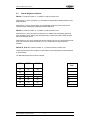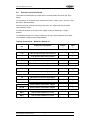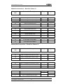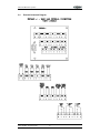
1
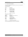
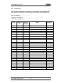
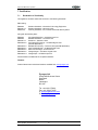
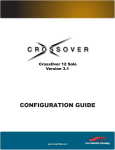
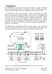
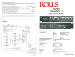
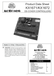
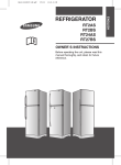
Quick Start Manual for PyroRack
Quick Start User Manual
&
Log Book
PyroRack
19” rack-mounted extinguishing and
detection unit
©2001 Pyrogen ltd
and its suppliers, all rights reserved
doc number PYR- rev0/01
1
Quick Start Manual for PyroRack
Important Note
This manual contains essential system & safety information, before
beginning any work involving the installation of PyroRack please read this
manual.
We would also advise that this manual be read in conjunction with the full
design and detailed installation manual.
In order to obtain a copy please contact your local distributor.
When installation is complete please keep this manual in a safe place.
We recommend that the installation and servicing of PyroRack should only be
carried out by suitably qualified personnel who have been trained accordingly.
This product is classed as
“NOT USER SERVICEABLE”
The use of non-recommended spares or parts or attempts at servicing other
than described herein will invalidate conformity and any warranty.
Copyright Notice
This document and the information that it contains is the property of Pyrogen
Limited. Any duplications or copies of this document should be done so only
with the written permission of Pyrogen Limited
© Copyright 2001 Pyrogen Ltd
©2001 Pyrogen ltd
and its suppliers, all rights reserved
doc number PYR- rev0/01
2
Quick Start Manual for PyroRack
Revision History
Amendment
No
Issue
Details
0
1
Initial Issue of Manual
Signed
Date
1
2
3
4
5
6
7
8
9
10
©2001 Pyrogen ltd
and its suppliers, all rights reserved
doc number PYR- rev0/01
3
Quick Start Manual for PyroRack
Contents
Chapter
Description
1.
Introduction
1.1
2.
Page
Introduction
5
Safety Information
2.1
2.2
3.
General Safety – Control Section
General Safety – Extinguishant Section
6
6,7
Quick Start / Installation
3.1
4.
Ten Simple Steps to Protection
8,9
Indications & Functions
4.1
4.2
4.3
5.
Indications
Functions
Fault Diagnostics
10
10
11,12
Technical Data
5.1
5.2
5.3
5.4
5.5
6.
Internal Connection Details
Internal Schematic Diagrams
Internal Engineers Switch Settings
External Connection Details
External Schematic Diagrams
13
14,15,16,17
18
19,20
21
Servicing
6.1
6.2
6.3
6.4
7.
User Checks
Engineer Checks
Recommended Service Spares
Service Log
22
22
23
24
Certification
7.1
7.2
Declaration of Conformity
Certificate of Installation & Commissioning
©2001 Pyrogen ltd
and its suppliers, all rights reserved
25
26
doc number PYR- rev0/01
4
Quick Start Manual for PyroRack
1. Introduction
1.1 Introduction
Representing the future in cabinet protection the 19” PyroRack is a self-contained automatic
fire extinguishing system, which can be used in many industry sectors.
Designed to be housed in 19” racking systems for the protection of delicate electronic
equipment, the PyroRack is fully capable of detecting a fire using single or coincidence
detection and responding by extinguishing the fire in less than 10 seconds of detection.
Signals can also be sent to other equipment via VFCC or RS232 to inform of the units status
and to key personnel for immediate investigation.
By siting the 19” PyroRack at the top of each equipment rack the individual piece of
equipment is being protected right at the heart of the potential risk, therefore more accurately
pinpointing the fire at a very early stage and eliminating the need to discharge large costly
amounts of fire suppressant.
The extinguishant section can be accessed after a discharge and the extinguishant agent
replaced as necessary.
Additional remote detectors and extinguishant units may be wired into to rear of the unit to
protect other areas or to provide additional coverage to the main cabinet.
The units are available in different size depths, which have been developed to protect
different sized cabinets.
This product has been designed, manufactured and tested under the stringent requirements
of:
ISO 9002
This product has been tested and conforms to the following standards:
EN55022, EN6100-3-2, EN50130-4,EN55022, EN55022, EN6100-3-2,
EN61000-4-6, EN61000-4-3, EN61000-4-4, EN61000-4-2, EN61000-4-5
EN61000-4-11
The installation of this product should be carried out by a competent person and comply with
the current editions of:
The IEE Wiring Regulations
The British Standard for Fire Detection and Alarm Systems for Buildings
(Or equivalent national standards where applicable).
©2001 Pyrogen ltd
and its suppliers, all rights reserved
doc number PYR- rev0/01
5
Quick Start Manual for PyroRack
2. Safety Information
2.1
General Safety – Control Section
2.1.1
Ensure Extinguishant is ISOLATED before carrying out any works.
2.1.2
Before beginning any work on the control section please read this manual carefully.
2.2.3
When working with the control unit, prior to the removal of any cover plates please
ensure the following steps are taken.
•
•
•
240v ac Supply is disconnected.
Extinguishant circuit is isolated.
Anti Static Protection is used when handling PCBs.
2.2
General Safety – Extinguishant Section Pyrogen
2.2.1
Ensure Extinguishant is ISOLATED before carrying out any works.
2.2.2
Before beginning any work, involving handling of the MAG generator, please read this
manual.
2.2.3
When working with the MAG generator it is forbidden to
• Disassemble the MAG generator
• Strike or impact the casing, or allow any other actions to occur which
could result in deformation or mechanical damage to the case or its
component parts.
• Carry out any hot work or allow smoking near to the MAG generator
or the thermal activation cord.
2.2.4
Should the generator be dropped check for visible signs of damage. Should there be
any doubt as to the unit’s functionality contact your supplier.
2.2.5
Toxicity: Inadvertent exposure to Pyrogen aerosol should always be
avoided. Toxicological information refers to an inadvertent exposure to the aerosol
in the event of accidental discharge in a non-fire situation.
The main ingredients of Pyrogen aerosol are solid potassium
carbonates, nitrogen gas, carbon dioxide gas and water vapour. At
normal extinguishing concentrations these products present little health
hazard to personnel. However, small amounts of potentially hazardous
by-products of the aerosol-generating combustion reaction, such as
carbon monoxide and nitrogen oxides will be produced. Their actual
concentrations depend on Pyrogen design factor used and type of
enclosure under protection. Their toxicological characteristics depend
upon the actual concentrations achieved and duration of exposure.
2.2.6
Re-entry: Following the use of Pyrogen, personnel should not enter the
protected area until it has been thoroughly ventilated. Exposure to the fire
by-products and extinguishant mixture should be avoided. Wearing a respirator or
other available means of protection may be required should it be necessary to enter
the area before it is fully ventilated.
©2001 Pyrogen ltd
and its suppliers, all rights reserved
doc number PYR- rev0/01
6
Quick Start Manual for PyroRack
2.2.7
Clean up: Following a system discharge the aerosol particles that have settled should
be vacuumed, blown, brushed or, if appropriate, washed away. Protective gloves
and goggles should be worn. A respirator or mask may be required.
2.2.8
Immediately after discharge the generators can be hot, therefore, protective
gloves should be worn before handling generators up to 15 minutes after discharge.
2.2.9
Dangerous Goods Classification: Pyrogen is a Class 4.1 article in accordance with
the United Nations Dangerous Goods Classification Code.
CoSHH Statement: A by-product of Pyrogen aerosol-generating combustion reaction
are fine potassium carbonate particles, small enough to be respirated by persons not
wearing RPE. There are no known toxicological long-term effects of these soluble
micron sized particles, and physiological effects of deep lung penetration are usually
a concern for insoluble sub-micron particles as they can interfere with pulmonary
functions.
There are clear European guidelines controlling the exposure of persons to fine
particles, irrespective of their nature. Further information is available in BS EN
481:1993 & BS EN 451:1993, and in CoSHH supportive documents EH40/98 & EH44
and MDHS 14/2.
©2001 Pyrogen ltd
and its suppliers, all rights reserved
doc number PYR- rev0/01
7
Quick Start Manual for PyroRack
3. Quick Start / Installation
3.1 Quick Start / Installation
Step 1:
Unpack your PyroRack:
Check List : 1 x PyroRack unit, 1 x mains lead, 2 x keys, 3 x connection
blocks, 2 x warning labels
Step 2:
Insert keys into panel and switch to “Isolate” position.
Step 3:
Remove cover from PyroRack by un-screwing small screws in top cover
plate.
Step 4a:
Install 2 x 1.2 a/h SLAB in space provided by first removing battery cover
plate.
Step 4b:
Connect batteries with leads provided.
Red lead to red (+) battery terminal on battery No 1
Black lead to black (–) battery terminal on battery No 2
Use link to connect black (–) battery terminal on battery No 1 to red (+)
terminal on battery No 2.
Place batteries upside down onto plastic spacers provided ensuring that the
terminals are spaced away from the metalwork.
Step 4c:
Replace battery cover plate ensuring it is fixed securely.
Step 5:
Replace main panel cover.
Step 6:
Securely position unit into the very top section of cabinet, which you are to
protect.
Step 7:
Ensure that discharge area at the rear of the unit is free from obstruction for
300mm below the discharge deflector; also the discharge deflector should be
close to the rear of the cabinet.
To ensure uniform discharge it is important that there are no
obstructions below the discharge area.
Step 8a:
Ensure key is inserted and switched to “Isolate” position.
Step 8b:
Plug main lead into rear of unit.
Step 8c:
Plug mains lead into a clean 230v ac Supply.
When initially plugged in the unit will carry out self-check, which will initiate all
lamps and sound buzzer.
The buzzer will now sound intermittent with a long pause indicating fault
condition.
Step 8d:
The panel should now be showing
“Fault” indication
“Isolated” indication
“Power On” indication
©2001 Pyrogen ltd
and its suppliers, all rights reserved
doc number PYR- rev0/01
8
Quick Start Manual for PyroRack
Step 8e:
At this stage the batteries are still not in circuit and require link to be inserted
into rear panel.
Step 9:
Ensure that fire indications are not lit and that Extinguishant released button
is not lit.
The keyswitch should be turned to the enable controls position and reset
button pressed.
The power on light should be the only indication lit and the buzzer should be
silent.
The keyswitch may now be returned to the “Normal” position.
Step 10:
Ensure that all doors are tightly shut on the cabinet and that all opening doors
have warning stickers attached.
Your cabinet is now protected by PyroRack
Should you find any difficulties in the above guide please contact your PyroRack distributor,
the above is only a guide and should be used by a fully trained engineer.
You should ensure that a maintenance contract is taken with a suitable experienced
company.
©2001 Pyrogen ltd
and its suppliers, all rights reserved
doc number PYR- rev0/01
9
Quick Start Manual for PyroRack
4. Indications & Functions
4.1
Indications
Indication
Description of indication
Colour
Power On
Panel is in operational mode
Green
Fault
Fault condition is apparent
Amber
Isolated
Extinguishant circuit is isolated
Amber
Fire
Fire condition has been detected
Red
Auxiliary/LP
Alarm condition has been detected
Amber
Released
Confirmation of extinguishant being released
Red
4.2
Functions
4.2.1
The following functions will only operate when the keyswitch is in “ Enable Controls “
position.
4.2.2
Function
Description of Function
Silence
When pressed will silence buzzer
Reset
When pressed a system reset is performed
Extract
Only operates after a fire condition, will reinstate the
switched voltage out put to rear when pushed.
The following functions will are for the keyswitch positions.
Function
Description of Function
Isolate
Isolate extinguishant circuit
Enable Controls
Enables the three push buttons – Silence, Reset, Extract
Normal
4.2.3
System should be left in this position when unattended
The “Extinguishant Release” emergency button will work in all situations with the
exception of the system being in the isolated position.
©2001 Pyrogen ltd
and its suppliers, all rights reserved
doc number PYR- rev0/01
10
Quick Start Manual for PyroRack
4.2
Fault Diagnostics
Fault Conditions : When a fault occurs on a part of the system the panel responds by
activating the internal sounder (which will pulse intermittently) and illuminating the fault light
(amber), the type of faults that would activate this are as follows:
The internal sounder may be silenced however this will still give a reminder every 15
seconds, which cannot be silenced until the fault is rectified.
The fault will automatically reset if the fault clears on its own, however this information is
logged in the event log memory for engineering purposes.
The following faults are numbered and if the system is reset and the fault remains on the
panel the diagnostics will illuminate the auxiliary function / low pressure light the amount of
times according to the fault number.
1 – Power Supply Fault
Cause – fault signal is detected from the power supply (mains failure)
Remedy – check all external fuses and that mains supply is present
2 – Battery Fault
Cause – fault signal is detected from the power supply (battery failure)
Remedy – check batteries are in circuit, check on rear external plate that battery link is in
place (batt), check batteries for signs of malfunction – corrosion, overheating, shape
distortion.
3 – Zone 1 Fault
Cause – open or short circuit fault is detected from detection circuit no 1
Remedy – check detector 1 is situated on base correctly, if no other detectors are being used
check that 6.8k end of line resistor is connected on rear external plate (Z1).
If other external detectors are being used check that they are all in place and that all are
situated on the bases correctly, also check that the end of line resistor is in place on the last
detector.
4 – Zone 2 Fault
Cause – open or short circuit fault is detected from detection circuit no 1
Remedy – check detector 2 is situated on base correctly, if no other detectors are being used
check that 6.8k end of line resistor is connected on rear external plate (Z2).
If other external detectors are being used check that they are all in place and that all are
situated on the bases correctly, also check that the end of line resistor is in place on the last
detector.
5 – Extinguishant Circuit / Actuator Circuit Fault
Cause – open circuit has been detected on the extinguishant circuit
©2001 Pyrogen ltd
and its suppliers, all rights reserved
doc number PYR- rev0/01
11
Quick Start Manual for PyroRack
Remedy – ensure that internal extinguishing actuators are in circuit, if fault persists they
should be changed, external ensure that the extinguishing actuators (Mag Units) are in circuit.
6 – Hold Circuit Fault
Cause – open or short circuit has been detected on hold circuit.
Remedy – check end of line resistor is in circuit 6.8k on rear plate (hold), rear connection
block is securely in place, any external wiring has end of line resistor fitted.
7 – Abort Circuit Fault
Cause – open or short circuit has been detected on abort circuit.
Remedy – check end of line resistor is in circuit 6.8k on rear plate (abort), rear connection
block is securely in place, any external wiring has end of line resistor fitted.
8 – Pressure Monitor / Auxiliary Circuit Fault
Cause – open or short circuit has been detected on pressure monitor circuit.
Remedy – check end of line resistor is in circuit 6.8k on rear plate (LP), rear connection block
is securely in place, any external wiring has end of line resistor fitted.
9 – Extinguishant Released Circuit Fault
Cause – open or short circuit has been detected on released circuit.
Remedy – check end of line resistor is in circuit 6.8k on rear plate (RLS’D), rear connection
block is securely in place, any external wiring has end of line resistor fitted.
10 – 24v Output Fuse
Cause – open circuit across fuse FH1
Remedy – check fuse and replace after determining fault which cause fuse to blow
©2001 Pyrogen ltd
and its suppliers, all rights reserved
doc number PYR- rev0/01
12
Quick Start Manual for PyroRack
5. Technical Data
5.1
Internal Connection Details
Connections – Board No: PyroRack V2 – “ Main Processor Card “
All connections on this card are for factory use only.
Connections – Board No: RedPSU V1 – “ Main Power Supply Card “
All connections on this card are for factory use only.
Connections – Board No: Redrly V2 – “ Relay Card “
All connections on this card are for factory use only.
Connections – Board No: Redcon 3 – “ Rear Internal Connection Card “
All connections on this card are for factory use only.
©2001 Pyrogen ltd
and its suppliers, all rights reserved
doc number PYR- rev0/01
13
Quick Start Manual for PyroRack
5.2
Internal Schematic Diagrams
©2001 Pyrogen ltd
and its suppliers, all rights reserved
doc number PYR- rev0/01
14
Quick Start Manual for PyroRack
©2001 Pyrogen ltd
and its suppliers, all rights reserved
doc number PYR- rev0/01
15
Quick Start Manual for PyroRack
©2001 Pyrogen ltd
and its suppliers, all rights reserved
doc number PYR- rev0/01
16
Quick Start Manual for PyroRack
©2001 Pyrogen ltd
and its suppliers, all rights reserved
doc number PYR- rev0/01
17
Quick Start Manual for PyroRack
5.3
Internal Engineers Switches
Switch 1: Located on board no – PyroRack V2 main processor card.
When switch 1 is in the up position (1) it will initiate the extinguishant release sequence upon
single activation.
When switch 1 is in the down position (2) it will instigate the panel to look for the second
activation before initiating the extinguishant release sequence.
Switch 2: Located on board no – PyroRack V2 main processor card.
When switch 2 is in the off position the decision as to weather the extinguishing agent has
been released is being made by the panel electrically, by determining that voltage has been
sent to the actuation circuit.
When switch two is in the on position the panel is looking for a input in to the RLS’D terminals
at the rear connection board no Redrear V1, from a confirmation the agent has been
released.
Switch 3a, 3b & 3c: Located on board no – PyroRack V2 main processor card.
These switches set the time of delay from the initiation of the extinguishant release sequence
to actual release.
The table below explains how this is achieved.
Delay
Time
SW3A
SW3B
SW3C
on
off
off
1
off
on
off
5
on
on
off
10
off
off
on
15
on
off
on
30
off
on
on
60
on
on
on
120
©2001 Pyrogen ltd
and its suppliers, all rights reserved
doc number PYR- rev0/01
18
Quick Start Manual for PyroRack
5.4
External Connections Details
Connections are detailed with the control panel in the fixed position from left to right, top to
bottom.
The 9 pin plug is for the RS232 / Palm Computer connection – NRZ Format, 1 start bit, 1 Stop
Bit, 8 Data – Baud Rate 9600.
All monitored inputs are monitored using a 6.8k-ohm E.O.L. resistor and firing is initiated
using a 680ohm resistor.
The male IES socket is for the input mains voltage 110/220 ac depending on voltage
selected.
The female IES socket is for a 10amp output to the fan unit or other equipment which needs
to be shutdown, voltage as input voltage selected.
Top Row Connections – Board No: Redrear V1
Connection
Ref
Connection Description
+ 48
+48 v dc Input to power unit in place of
←
-
0 v dc Input to power unit in place of
←
Abort
Monitored Abort Signal
←
Abort
Monitored Abort Signal
←
Hold
Monitored Hold Signal
←
Hold
Monitored Hold Signal
←
LP
Monitored Low Pressure Input Signal
←
LP
Monitored Low Pressure Input Signal
←
RLS`D
Remote Actual Confirmation of Agent
←
RLS`D
Remote Actual Confirmation of Agent
←
BATT
Link to connect batteries in circuit
BATT
Link to connect batteries in circuit
©2001 Pyrogen ltd
and its suppliers, all rights reserved
Output
Input
→
←
doc number PYR- rev0/01
19
Quick Start Manual for PyroRack
Middle Row Connections – Board No: Redrear V1
Connection
Ref
Connection Description
Output
→
Input
←
Trig
Remote Firing Circuit Input for Agent
←
Trig
Remote Firing Circuit Input for Agent
←
Z2
+ Zone Two Detection Circuit
←
Z2
- Zone Two Detection Circuit
←
Z1
+ Zone One Detection Circuit
←
Z1
- Zone One Detection Circuit
←
Gas
+ Output to Remote Units
→
Gas
- Output to Remote Units
→
24
24v dc Output rated @ 500mA
→
0v
0v dc Output rated @ 500mA
→
Bottom Row Connections – Board No: Redrear V1
Connection
Ref
Connection Description
Output
→
NC
Fault - Normally Closed Volt Free Contact
→
NO
Fault - Normally Open Volt Free Contact
→
C
Fault - Common Volt Free Contact
→
NC
Fire 2 - Normally Closed Volt Free Contact
→
NO
Fire 2 - Normally Open Volt Free Contact
→
C
Fire 2 - Common Volt Free Contact
→
NC
Fire 1 - Normally Closed Volt Free Contact
→
NO
Fire 1 - Normally Open Volt Free Contact
→
C
Fire 1 - Common Volt Free Contact
→
©2001 Pyrogen ltd
and its suppliers, all rights reserved
Input
←
doc number PYR- rev0/01
20
Quick Start Manual for PyroRack
5.4
External Schematic Diagram
©2001 Pyrogen ltd
and its suppliers, all rights reserved
doc number PYR- rev0/01
21
Quick Start Manual for PyroRack
6. Service
6.1
User Checks
6.1.1
Ensure Extinguishant is ISOLATED before carrying out any works.
6.1.2
The user should ensure that the system is in good working order at all times. The
user should carry out on a monthly basis inspections of the system, these should
include:-
6.1.3
The initiation of the reset button, which will perform a self-check of the control
circuitry, all lights should indicate and buzzer sound once.
6.1.4
Looking out for obstructions to the discharge area, alteration / extensions of protected
equipment.
6.1.5
Checking all openings, which should be securely closed is not left in the open
position.
6.1.6
Area is free from dust or other foreign objects, which could cause unwanted false
alarms.
6.2
Engineer Checks
6.2.1
Ensure Extinguishant is ISOLATED before carrying out any works.
6.2.2
The responsible person should ensure that every 3 months the following checks are
carried out by a competent person:-
6.2.3
Entries in the Log Book are checked and any necessary action taken.
6.2.4
Batteries and their connections should be examined and tested to ensure they are in
a good serviceable condition and not likely to fail before the next quarterly inspection.
6.2.5
The alarm functions of the control and indicating equipment by operation of a
detector.
6.2.6
Visual inspection as in 6.1.4
6.2.7
Any defects should be recorded in the logbook and reported to the responsible
person, and action taken to correct it.
6.2.8
On completion of the work, a certificate of testing should be given to the responsible
person.
©2001 Pyrogen ltd
and its suppliers, all rights reserved
doc number PYR- rev0/01
22
Quick Start Manual for PyroRack
6.3
Recommended Service Spares
We recommend that the following spare parts be kept in the event of the unit being damaged
or the agent being released.
Replacement Mag Units:
Part No
Description
Mag 1
Mag 2
Mag 3
Mag 1 Aerosol Generator
Mag 2 Aerosol Generator
Mag 3 Aerosol Generator
F/H1
F/H2
F/H3
Filter Housing for Mag 1
Filter Housing for Mag 2
Filter Housing for Mag 3
F/U
Filter Unit – fits all housings.
Replacement Circuit boards etc.
PyroRack V2
Redcon3
Redrly V2
RedPSU V1
Processor card
Rear card, also comes with Redrear card
Relay Card
Power Supply Card
TZ1100
TZ1101
TZ1102
TZ1105
Optical Smoke Detector
Ionisation Smoke Detector
60deg Combined Heat Detector
60deg Heat Fixed
TZ1.2/12
1.2a/h Sealed Lead Acid Batteries
For prices and availability please contact you local distributor.
©2001 Pyrogen ltd
and its suppliers, all rights reserved
doc number PYR- rev0/01
23
Quick Start Manual for PyroRack
6.4
Service Log
Any changes, modifications, and repairs to the system or its components are
to be noted on these pages. All recordings must contain date and signature.
Date of Installation:………………………….
Installation Completed by:……………………………………………………
On Behalf of: (Company):……………………………………………………
Date
Panel Ref
No.
©2001 Pyrogen ltd
and its suppliers, all rights reserved
(P) Pass
(F) Fail
Action
Signature
doc number PYR- rev0/01
24
Quick Start Manual for PyroRack
7. Certification
7.1
Declaration of Conformity
This appliance has been tested and conforms to the following standards:
EMC testing:
EN55022
EN6100-3-2
EN50130-4
Emission Standard – Information Technology Equipment
Emission Standard – Harmonic Limits
Immunity Standard – Fire, Intruder and Social Alarm Systems
Along with the following tests:
EN55022
EN55022
EN6100-3-2
EN61000-4-6
Conducted Emissions – AC Mains Input Port
Radiated Emissions – Enclosure Port
Emissions – Harmonic Limits
Conducted RF Immunity – AC Mains/Signal Lines
(AM+PM Modulation)
EN61000-4-3 Radiated RF Immunity – Enclosure Port (AM+PM Modulation)
EN61000-4-4 Fast Transient Bursts – AC Mains/Signal Lines
EN61000-4-2 Electronic Discharge – Enclosure Port
EN61000-4-5 Voltage Surges – AC Mains / Signal Lines
EN61000-4-11 Voltage Dips – AC Mains Input Port
Documentation is available at the companies address:
Contact:
Product literature and other downloads are available from www.pyrogen.com
Pyrogen Ltd
Gilnow Mill Business Centre
Spa Road
Bolton
Lancashire
BL1 4LF
Tel: +44 1204 373300
Fax: +44 1204 373355
E: [email protected]
W: www.pyrogen.com
©2001 Pyrogen ltd
and its suppliers, all rights reserved
doc number PYR- rev0/01
25
Quick Start Manual for PyroRack
Certificate of Installation
&
Commissioning
This certificate confirms the installation and commissioning of the fire alarm and
suppression system (PyroRack) at:
Protected Area Specific:………………………………………………………………
Premises / Address:…………………………………………………………………...
………………………………………………………………………………………..
………………………………………………………………………………………..
The above system has been installed & commissioned in line with the manufacturers
guidelines:
Signed (Commissioning Engineer):………………………………..Date:…………….
For and on behalf of:…………………………………………………………………..
In case of emergency contact no:……………………………………………………...
This manual is to situated at:………………………………………………………….
Official Use:
Panel Serial No:…………………………………………………………………………
Goods inspected and packed on:………………….Signature:…………………………
©2001 Pyrogen ltd
and its suppliers, all rights reserved
doc number PYR- rev0/01
26