1
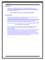
Fire Mermaid X1
This manual contains essential system
and safety information and should be stored
in a safe place accessible to all boat users
Installation and User manual for
FIRE MERMAID X1
Fire Extinguishing System
Page 1 of 35
Fire Mermaid X1
Contents
1. User Instructions ..................................................................................................... 4
Fire ..................................................................................................................... 4
Alarm.................................................................................................................. 4
Fault ................................................................................................................... 4
Alarms ................................................................................................................ 5
Fire Alarm........................................................................................................... 5
Fire Extinguishing............................................................................................... 5
Fault Light........................................................................................................... 5
Functions Description......................................................................................... 6
Fire ..................................................................................................................... 6
Fault ................................................................................................................... 6
After Discharge................................................................................................... 6
2. Main system components ....................................................................................... 7
General............................................................................................................... 7
Pyrogen Canister................................................................................................ 7
Contents ............................................................................................................. 7
Fire Extinguishing............................................................................................... 7
The Control Panel .............................................................................................. 8
Monitoring........................................................................................................... 8
Start.................................................................................................................... 8
3. Service.................................................................................................................... 9
General............................................................................................................... 9
The Regular Visual Inspection............................................................................ 9
10 Year Service.................................................................................................. 9
After Discharge................................................................................................... 9
Recommended Procedure for Replacement .................................................... 10
Disposal............................................................................................................ 10
4. Installation............................................................................................................. 11
General............................................................................................................. 11
Installation Procedure....................................................................................... 12
Material............................................................................................................. 12
Tools................................................................................................................. 12
Order of Connection ......................................................................................... 12
Control Panel Mounting .................................................................................... 13
Pyrogen Canister Mounting .............................................................................. 13
The Control Panel ............................................................................................ 14
General............................................................................................................. 14
Connections ..................................................................................................... 15
Settings (Programming).................................................................................... 15
Wires ................................................................................................................ 15
Auxiliaries ......................................................................................................... 16
Sensor Cable.................................................................................................... 16
The Pyrogen Canister....................................................................................... 17
Page 2 of 35
Fire Mermaid X1
5. Trouble shooting ................................................................................................... 18
No Light in the Control Panel............................................................................ 18
Fault is Lit......................................................................................................... 19
Fire is Lit........................................................................................................... 20
External Alarms ................................................................................................ 21
General............................................................................................................. 21
6. Accessories and Spare Parts................................................................................ 22
Kits ................................................................................................................... 22
Included in the Kit............................................................................................. 22
Accessories ...................................................................................................... 22
Spare Parts ...................................................................................................... 23
7. Pyrogen Safety Data............................................................................................. 25
Limitations ........................................................................................................ 25
Height Limitation............................................................................................... 25
Safe Distance ................................................................................................... 25
Visibility ............................................................................................................ 25
Oxygen Levels.................................................................................................. 25
Toxicity ............................................................................................................. 26
Post Fire Exposure........................................................................................... 26
Thermal Hazard................................................................................................ 26
Hot Work .......................................................................................................... 26
Re-entry............................................................................................................ 27
Clean-up........................................................................................................... 27
Dangerous Goods Classification ...................................................................... 27
CoSHH Statement............................................................................................ 27
Noise ................................................................................................................ 27
8. Technical Specification ......................................................................................... 28
9. Fire Procedure ...................................................................................................... 30
10. Commissioning Check List.................................................................................. 31
11. Service Log ......................................................................................................... 32
12. Declaration of Conformity.................................................................................... 33
13. Installation Templates ......................................................................................... 34
Control Panel.................................................................................................... 34
Pyrogen Canister Mounting .............................................................................. 35
Observe Safety Information in Section 7 (page 25)
Page 3 of 35
Fire Mermaid X1
1. User Instructions
Fire
When a fire in the engine room is discovered:
1.
Check that the engine room has been evacuated.
2.
Close the engine room and shut down ventilation.
3.
Shut-off the engine.
4.
Press both discharge buttons simultaneously for 5 seconds.
(Must be done immediately after engine shut-off)
5.
Disconnect all power supplies. (electric/gas/fuel)
6.
Perform a role call.
7.
Check that everybody is present and unhurt.
8.
Think safety. (life jackets, anchoring, flares, alert coast guard etc.)
9.
After 5 minutes verify that the fire is extinguished.
(Only open the hatches slightly, caution must be used not to become
exposed to the fire or its bi-products)
10. Only restart engine once the cause of the fire has been repaired/mended.
Alarm
When an alarm appears on the control panel:
1.
Check if it is a fire or a fault alarm.
2.
If it is a fire see above “Fire”.
3.
If it is a fault see below “Fault”.
Fault
When a fault occurs:
1.
Disconnect all power to the control panel.
2.
Disconnect the Pyrogen canister.
3.
Find the fault and repair it.
4.
Reconnect the power supply.
5.
Reconnect the Pyrogen canister.
6.
Verify that the fault alarm does not reappear.
Page 4 of 35
Fire Mermaid X1
Alarms
Fire
=
Flashing light and pulse sound (and beacon).
Discharge
=
Continuous light and continuous sound (and beacon).
Fault
=
Continuous light and pulse sound (and beacon).
Fire light flashes, horn is pulsating (beacon flashes)
Fire Alarm
When either discharge buttons have been activated, or the sensor cable has
melted, (burned) (only when the control panel is in automatic, see J1 page 15)
the fire extinguisher will discharge after approx. 5 seconds warning.
In the event of an automatic alarm it should be verified immediately, to check if
it is a fire or what has caused the alarm. The sounder (and beacon) can be
turned off by pressing the button “Reset Sound”; the alarm will still be active and
discharge the fire extinguisher approx. 5 seconds after the alarm started.
Fire flashes, fault and horn is continuous (beacon is continuous)
Fire Extinguishing
When the fire extinguisher has been discharged, the horn and beacon can be
turned off by pressing the “Reset Sound” button. “Fire” and “Fault” indicators will
still be on at the control panel until the sensor cable and the fire extinguishers
are replaced.
If the fire extinguishing was activated by the sensor cable, the “Fire” light on the
control panel will remain lit until the sensor cable has been
replaced/disconnected. If the sensor cable is disconnected, the “Fault” light will
be indicated on the control panel until the sensor cable is replaced/reconnected.
Fault lights, horn pulses (beacon flashes)
Fault Light
If “Fault” is lit and no other indications are lit, a fault has occurred on the
system, see the next page.
Page 5 of 35
Fire Mermaid X1
Functions Description
Fire
When the sensor cable is shorted (this happens at 105°C) the control panel will
indicate “Fire” (see previous page). If the two discharge buttons “Discharge” on
the front of the control panel are activated simultaneously a fire will also be
indicated. After 5 seconds of warning the fire extinguisher is activated. The relay
Fault/Fire (port 10+11) will operate whether or not jumper J2 is installed (see
page 15).
During a fire indication the light and sounder are pulsating/flashing.
When the fire extinguisher is activated, the beacon and sound will shift to
continuous.
When the fire extinguisher is activated a “Fault” indication will appear. (see
below)
If the sounder is reset manually (by pushing the button “Reset Sound”) the
sounder and beacon will be turned off.
Fault
When a fault occurs on the system the control panel will indicate “Fault”. (see
previous page)
The relay Fault/Fire (port 10+11) will change if jumper J2 is installed. If jumper
J2 is not installed the relay will not operate (if the relay is used to control
ventilation in the engine room, it is not desirable to have the ventilation stopped
due to a fault, and it should only be stopped in the event of a fire).
After Discharge
When the system has discharged it will not function until it has been re-installed.
The Pyrogen unit must be replaced.
See section 3 (page 9) “Service” and “After Discharge”
Page 6 of 35
Fire Mermaid X1
2. Main system components
General
Fire Mermaid X1 is designed to control fire extinguishing systems in boats. The
extinguishing system is Pyrogen.
Pyrogen canisters are activated directly by an electrical impulse.
Pyrogen Canister
Contents
The aerosol generating chemical is a thermoplastic mixture consisting of an
oxidiser, a combustible binder and additives. The oxidiser is solid potassium
nitrate (KNO3), the binder is solid plasticised nitro-cellulose (CnHmNpOq) and
other ingredients for stabilisation.
Combustion products of the aerosol-generating chemical half consist of
potassium carbonate (KHCO3, K2CO3), carbon dioxide (CO2), nitrogen (N2) and
water (H2O) and represent the actual extinguishing agent, completely
environmental friendly.
Fire Extinguishing
Pyrogen is mainly potassium carbonate formed in the gas phase. It condenses
to a liquid and then a solid form producing a large number of micron sized
particles. Being so small, the particles produce a large surface area increasing
the efficiency.
The micron sized aerosol particles exhibit a gas like 3-dimensional quality that
allow the agent to rapidly distribute throughout the enclosure and reach the
most concealed and shielded location.
The typical design factor (when dimensions of room/MAG are kept to within the
limits stated in this manual) is 100g/m3.
Page 7 of 35
Fire Mermaid X1
The Control Panel
The Fire Mermaid X1 is a compact control panel which can be fitted to any boat.
The Fire Mermaid X1 is easily installed and offers a high class finish to the
boats instrumentation. The panel is water proof when installed due to the high
end membrane switches used in the all sealed front panel.
Monitoring
The detector loop is continuously monitored when the control panel is on. If the
cable or detector is disconnected, a “Fault” indication will appear. When the
control panel is turned off the detector loop remains active. A fire will cause the
control panel to come on and discharge the fire extinguisher. (as long as the
battery is connected).
The discharge loop is monitored, if the connection to the fire extinguisher is
disconnected a “Fault” will also be indicated.
Start
When the ignition is switched to “On” the control panel will perform a start-up
procedure. When the ignition has been on for approx. 1½ minutes the control
light “Ready” will be lit green on the control panel (it is not possible to discharge
the fire extinguisher during the start-up procedure).
When the boat ignition is switched off the system can not be activated manually.
The detector port is still active. If the detector port is shorted (the sensor cable
shorts at 105°C) the control panel will perform an auto-start and activate the fire
extinguisher after approx. 15 seconds. If the batteries are completely
disconnected the control panel will not be able to perform the activation.
The sole purpose of having the control panel on standby is to save energy.
Page 8 of 35
Fire Mermaid X1
3. Service
General
Fire Mermaid X1 is a maintenance free system as it is self monitoring. The
condition of wire connections, plugs and auxiliary equipment should be
inspected visually on a regular basis in order to prevent damage and faults from
occurring.
The Regular Visual Inspection
•
All wires are secured.
•
No wires have poor insulation.
•
All connections are clean and sealed.
•
No moisture is present in connections and there is no corrosion.
•
The Pyrogen canister is less than 10 years old.
•
The Pyrogen canister is free from dents/markings or any damage.
10 Year Service
•
Replace the Pyrogen canister.
For proper disposal of undischarged Pyrogen canisters contact:
Pyroshield Ltd.
Unit 11, Westbrook Trading Estate,
Trafford Park,
Manchester, UK.
M17 1AY.
Tel:
Fax:
e-mail:
+ 44 (0) 161 877 0077
+ 44 (0) 161 877 0078
[email protected]
After Discharge
The Pyrogen canister must be replaced after discharge. If the fire extinguisher
was activated by the sensor wire then that too must also be replaced. (see the
section Pyrogen canister and Sensor cable in the chapter “Installation”).
Page 9 of 35
Fire Mermaid X1
Recommended Procedure for Replacement
1.
Disconnect both power supplies to the control panel.
2.
Disconnect the Pyrogen/actuator canister.
3.
Remove the Pyrogen canister from its brackets.
4.
Remove the old and install a new sensor cable.
5.
Install a new Pyrogen canister. (replace brackets if necessary)
6.
Connect the wire plug to the Pyrogen canister.
7.
Connect power to the control panel.
8.
Turn the ignition on.
9.
Verify that there are no fault indications on the panel.
Disposal
Following activation, the Pyrogen canister contains no harmful matter and may
be disposed of by using conventional household refuse facilities. Alternatively
some distributors may offer a financial incentive to return the old unit to them.
Page 10 of 35
Fire Mermaid X1
4. Installation
Wiring diagram of the FIRE MERMAID X1 system
(two Pyrogen canisters are shown)
General
Before any work is started the motor must be stopped and the battery +ve.
terminal must be disconnected. Do not connect the battery terminal before the
installation is completed. Prepare the installation very carefully, have all the right
tools and materials ready before the installation is started.
Warning:
The Pyrogen canister may be activated by exposure to
flames and Heat. Avoid exposing the Pyrogen canister
to elevated temperatures or direct sunlight.
Page 11 of 35
Fire Mermaid X1
Installation Procedure
The material below must be available for installation.
Material
1.
Sufficient wire with an area of =1mm2. It is recommended to use fire
resistant wire (IEC 331).
2.
Available outlet on the fuse box, (minimum 2Amp) a suitable inline fuse
may be used.
Tools
1.
No. 2 plain screwdriver and Pozi 1+2 screwdriver.
2.
T20 Torx screwdriver.
3.
Drill with 3mm and 10mm drill bit.
4.
Electric jigsaw.
Order of Connection
1.
Turn off the engine and disconnect the battery +ve. terminal.
2.
Make the cut out for the control panel. (see page 13)
3.
Install the Pyrogen canister and sensor cable. (see pages 16,17)
4.
Install the connection box in the vicinity of the engine room.
5.
Connect the sensor cable to the connection box. (see page 16)
6.
Place/check SW1, J1 and J2 in the desired position. (see page 15)
7.
Install wires from the connector box to the control panel.
8.
Connect horn and optional beacon.
9.
Connect other auxiliary equipment. (ventilation)
10.
Connect the wires in the connection box. (see page 15)
11.
Connect the wires at the control panel.
12.
Connect wires from the ignition switch to the control panel.
13.
Connect the control panel to the fuse box. (or inline fuse) (see page 15)
14.
Reconnect the battery.
15.
Verify that all connections are correctly made; check the light on the
control panel with ignition on.
16.
Check that no fire is indicated on the control panel.
17.
Connect the Pyrogen canister.
Page 12 of 35
Fire Mermaid X1
Control Panel Mounting
Cut out the template in the back of this manual by cutting along the grey line.
(100mm x 130mm).
Place the template on the dashboard in the cockpit, in the desired position, (it
must be a place which is easily accessible) to which the access will not be
limited in the event of a fire in the engine room.
The template should be placed so that the diagonal lines, where the holes are
to be drilled, are placed downwards. Double sided sticky tape may be use to
secure the template during installation.
The control panel must be easily accessible
in the event of an engine fire
•
Mark with a sharp pointer the 6 corners in the cut-out. Mark the centre of
the 10mm hole and the 4 screw holes.
•
Drill a 10mm hole in the bottom left corner.
•
Use a jigsaw to make the cut-out in the dashboard. The cut-out must
follow the full black lines on the template. To make sharp corners it may
be necessary to cut from both sides. Use the correct jigsaw blade
according to the dashboard material.
•
File off any rough edges, using a suitable file.
•
Unwrap the control panel and verify that it will fit the cut-out without
interfering with the dashboard. Verify that the screw marks line up as well.
Pyrogen Canister Mounting
An Ideal mounting would be right on the bulkhead high up in the engine space
pointing towards the engine. This way the Pyrogen will be distributed evenly
over the engine which is the potential fire hazard.
Page 13 of 35
Fire Mermaid X1
FIRE MERMAID X1
The Control Panel
General
The terminals are screw terminals. Wires must have bared and soldered ends
before being inserted into the desired terminal; the screw is then tightened to
secure the wire.
It is recommended that only one wire is connected in each terminal.
J is a jumper. A jumper is a plastic cover with metal poles on the inside. (see
page 15) It will short the terminals which it is placed in.
When the jumper is removed the terminal is no longer shorted.
SW1 is a switch which may be placed in to positions by turning it with a
screwdriver. (see page 15)
Page 14 of 35
Fire Mermaid X1
Connections
+ Battery:
To the battery +ve. terminal (remember fuse)
- Battery:
To the battery -ve. terminal.
+ Ignition:
To the main or ignition switch (note it must be supplied from the
battery +ve. terminal).
+, - Sensor:
Connection for the sensor cable. + and - sensor is shorted during
fire.
+, - Extinguish:
Power to activate the fire extinguisher (monitoring current when
the control panel is on).
+, - Spare:
Must be shorted. An open circuit will result in a “Fault” indication.
1, 2 Fault/Fire:
Relay which may be used for auxiliary alarm or to control engine
room ventilation.
+, - Sounder:
Sounder and beacons are connected here.
Settings (Programming)
J1:
If J1 is fitted the system can only be activated manually.
If J1 is not fitted (Factory default) the system may discharge both
automatically (sensor cable) and manually (buttons on control panel front).
J2:
If J2 is fitted (Factory default) the relay Fault/Fire will operate on both fault
and fire alarm.
If J2 is not fitted the relay Fault/Fire will only activate on Fire alarms.
SW1: If SW is active the Fault/Fire terminal is “Normally Closed” and the circuit will
break during a Fire/Fault. (for use with engine room ventilation, fuel pump,
engine shut down etc.)
If SW1 is inactive (Factory default) the Fault/Fire terminal is “Normally Open”
and the circuit will close on Fire/Fault.
Wires
Wires from the control panel and to the sensor cable and MAG canister must
be shielded and be of shortest possible length.
Wires must have a cross sectional area of at least 0.6mm2, and the maximum
acceptable length must not exceed 20m.
Page 15 of 35
Fire Mermaid X1
Auxiliaries
Sounders and optical lights/beacons must be placed so that they can be
observed from the typical control points. It may be necessary to purchase and
install extra sounders or lights/beacons to ensure that they can be observed
from any point on the boat.
Beacon/lights and sounders must be easily observable
Sensor Cable
The sensor cable is supplied complete with an “end of line resistor” and only
needs to be connected at one end to work properly.
The cable is placed in the top of the engine room in a way so that a fire will melt
the cable. The cable may be secured with cable ties, clips or similar. The cable
must be placed freely so that flames can reach the cable from all sides.
When locating the sensor cable caution should be observed, so as not to place
it directly over hot exhaust manifolds, as the sensor cable will activate at 105°C.
Do not shorten the sensor cable
When installing the sensor cable it is important not to damage it. Cable ties
should not be tightened so hard that the wires inside the cable may be
squeezed together.
If a pre made sensor cable is not used, the end of line resistor must be soldered
on prior to installation. Bare 1cm of the cable and solder the resistor to the
bared wire. Apply insulation tape is to each bared wire. After it has been
measured that the resistor is soldered correctly and the wires are not shorted,
the protective cap is fitted and heat shrinked on with a hot air gun, care must be
taken not to damage the sensor cable during this operation.
Page 16 of 35
Fire Mermaid X1
The Pyrogen Canister
The bracket for the Pyrogen canister must be mounted so that the Pyrogen
canister is placed in an effective position. It is important that the outlet of the
Pyrogen canister is not pointing directly at a wall, escape route, or in a direction
where an unintended discharge may expose danger to man or material, (see
page 24) for distances that must be observed.
If the Pyrogen canister is of the mono nozzle type (only one protective cover) it
should be placed so that it will discharge the Pyrogen over the engine room (the
rear side of the canister should be placed toward the engine room wall). If it is
the Bi-directional type the Pyrogen canister should be placed in the middle of
the room.
If more than one Pyrogen canister is to be connected to one control panel they
must be connected in parallel.
See page 24 for necessary precessions when installing the canister.
Page 17 of 35
Fire Mermaid X1
5. Trouble shooting
No Light in the Control Panel
Check that power to the control panel is connected correctly.
Check that the ignition is on and has been on (continuously) for at least 2 minutes.
Check that there is +12V. D.C. at the control panel.
Check the fuse.
Page 18 of 35
Fire Mermaid X1
Fault is Lit
Check that “Spare” is shorted.
Check that the sensor cable is connected and that the “end of line” resistor (43 KΩ) is
correctly installed.
Check all connections (note: A build up of dirt and corrosion may cause the system to
malfunction).
Page 19 of 35
Fire Mermaid X1
Fire is Lit
The sensor cable port is shorted.
Disconnect the sensor cable connection in the connection box (by the engine room)
and press the “Reset Sounder” for 3 seconds. If the fire indication does not
disappear, the cable between the control panel and the connection box is damaged.
When a faulty wire is found it must be replaced. It is not recommended to mend or
repair a faulty wire, the whole wire should be replaced.
Page 20 of 35
Fire Mermaid X1
External Alarms
General
When extra equipment is installed to the system it should be verified that the rating
does not exceed the specification of the control panel.
If problems occur always check that the equipment is functioning correctly before
fault finding on the control panel/system.
Connected to “Sounder” or “Light/Beacon”
Check that the terminals on the sounder or light/beacon are connected properly and
that they are clean.
Check that wires are not shorted.
Connected to the Fault/Fire terminals
Check the position of SW1; if SW1 is active the relay will open upon alarm. (when
connected to the ventilation etc.) If SW1 is inactive the relay will close upon alarm
(alarm horns etc.).
Check the position of J2, if the jumper is fitted the relay will only operate on a fire
alarm (e.g. ventilation), a fault alarm will not have any effect on the relay when J2 is
fitted. If J2 is not fitted a fault will also cause the relay to operate.
Page 21 of 35
Fire Mermaid X1
6. Accessories and Spare Parts
Kits
Model
Engine
Room m3
Item No.
MAG-2
=1.0
528301
MAG-3
=2.0
528302
2 x MAG-3
=4.0
528304
MAG-5
=5.0
528305
MAG-5+3
=7.0
528307
MAG-4
=10
528310
2 x MAG-4
=20
528310 + 304210
3 x MAG-4
=30
528310 + 2 x 304210
Designation
Fire Mermaid
1m3 MAG
Fire Mermaid
2m3 MAG
Fire Mermaid
4m3 MAG
Fire Mermaid
5m3 MAG
Fire Mermaid
7m3 MAG
Fire Mermaid
10m3 MAG
Fire Mermaid
20m3 MAG
Fire Mermaid
30m3 MAG
Included in the Kit
The kit include control panel, sensor cable, connection boxes, sounder, plugs
screws etc. as well as the MAG unit(s) for the specified installation.
Accessories
Designation
Dim. (mm)
Item No.
Sensor Cable
c/w End of Line Resistor
4 meter
528012
per meter
101150
Sensor Cable
End of Line Resistor
Sensor cable Resistor
Cap
Sign
(Engine Room Warning)
515166
505305
105 x 149
528330
Sign (For Windscreen)
149 x 74
528331
5W Red Beacon
ø75 x 95
407022
Sounder
ø90 x 35
406030
Page 22 of 35
Fire Mermaid X1
Spare Parts
Designation
Pyrogen
Mag-2
Pyrogen
Mag-3
Pyrogen
Mag-5
Pyrogen
Mag-4
Installation
Manual
Installation
Diagram
Max Room
Volume (m3)
Dim. (mm)
Weight
(kg)
Item
No.
1
ø75 x 95
0.50
304201
2
ø75 x 145
0.70
304202
5
ø95 x 190
1.83
304205
10
ø95 x 350
4.50
304210
A5
528360
A3
528367
6.3 mm
516100
Distribution
Box
70 x 70 x 37
706450
SS Screws
UHT 4 x 20
401443
Cable Socket
Sounder
Fire Proof
Cable
501853
2 x 0.75
IEC 331
101142
Page 23 of 35
Fire Mermaid X1
Pictures of different Pyrogen MAG Canisters
Vehicle kit shown
MAG-3 Pyrogen Canister
Control Panel after installation
Sounder at top corner and ignition switch in lower right corner.
Page 24 of 35
Fire Mermaid X1
7. Pyrogen Safety Data
Limitations
The Pyrogen extinguishant, being a hot aerosol, has a tendency to rise upward
on its release due to buoyancy forces. As such, the aspect of spatial distribution
needs to be addressed.
Height Limitation
MAG-2
1.25m
MAG-3
2.50m
MAG-4
3.00m
MAG-5
3.00m
Due to potential hazard of high temperatures below minimum distances should
always be observed during installation.
Safe Distance
MAG-2
400mm
MAG-3
1000mm
MAG-4
1300mm
MAG-5
700mm
Visibility
Pyrogen is intended to be used in normally unoccupied areas principally due to
the high obscuration caused by the aerosol during and after discharge.
Oxygen Levels
Pyrogen chemically attacks the fire, breaking the flame chain reaction. It does
not extinguish fires by oxygen depletion. After discharge, oxygen levels will
remain at or about normal.
Page 25 of 35
Fire Mermaid X1
Toxicity
Inadvertent exposure to Pyrogen aerosol should always be avoided.
Toxicological information refers to an inadvertent exposure to the aerosol in the
event of accidental discharge in a non-fire situation.
The main ingredients of Pyrogen aerosol are solid potassium carbonates,
nitrogen gas, carbon dioxide gas and water vapour. At normal extinguishing
concentrations these products present little health hazard to personnel.
However, small amounts of potentially hazardous by-products of the aerosolgenerating combustion reaction, such as carbon monoxide and nitrogen oxides
will be produced. Their toxicological characteristics depend upon the actual
concentrations achieved and duration of exposure.
Exposure to Pyrogen in a standard system, for up to
5 minutes, is considered to represent a minor risk to
personnel and may cause moderate local irritation
of the upper respiratory tract and to the eyes.
Post Fire Exposure
One of the key advantages of Pyrogen over Halon and some of the replacement
agents available is that Pyrogen does not produce toxic nor highly corrosive
halogen acids when exposed to fire or hot surfaces. Safety requirements
dictate, however that unnecessary exposure to post-fire atmospheres should be
avoided.
Caution
Venting of the post-fire atmosphere should be to an open-air area, when
possible, to prevent the inadvertent exposure of personnel to any combustion
products of the fire and aerosol-generating reaction.
Thermal Hazard
There is a potential hazard of high temperatures (250°C+) of Pyrogen aerosol at
the end-plate nozzle. Outside the safe distance the temperature does not
exceed 75°C. Those distances should be observed during installation.
Immediately after discharge the generators can be hot,
therefore, protective gloves should be worn before
handling generators up to 15 minutes after discharge.
Hot Work
As naked flame or prolonged exposure to temperatures above 400°C (105°C for
the sensor cable) may cause activation of the generators, hot work must not be
carried out within the vicinity of any generators. If so they shall be removed prior
to any hot work being carried out.
Page 26 of 35
Fire Mermaid X1
Re-entry
Following the use of Pyrogen, personnel should not enter the protected area
until is has been thoroughly ventilated. Exposure to the fire by-products and
extinguishant mixture should be avoided.
Wearing a respirator or other available means of protection may be required
should it be necessary to enter the area before it is fully ventilated.
Clean-up
Following a system discharge the aerosol particles that have settled should be
vacuumed, blown, brushed or, if appropriate, washed away. Protective gloves
and goggles should be worn. A respirator or mask may be required
Large amounts of residue that is allowed to absorb moisture
become electrically conductive over a period of time.
Dangerous Goods Classification
Pyrogen is a Class 4.1 article in accordance with the United Nations Dangerous
Goods Classification Code.
CoSHH Statement
A by-product of Pyrogen aerosol-generating combustion reaction are fine
potassium carbonate particles, small enough to be respirated by persons not
wearing RPE. There are no known toxicological long term effects of these
soluble micron sized particles, and physiological effects of deep lung
penetration are usually a concern for insoluble sub-micron particles as they can
interfere with pulmonary functions.
However, there are clear European guidelines controlling the exposure of
persons to fine particles, irrespective of their nature.
Further information is available in BS EN 481:1993 and BS EN 451:1992 and in
CoSHH supportive documents EH40/98 and EH44 and MDHS 14/2.
Noise
The sound output and frequency at the time of activation and during discharge
is similar to the produced by other extinguishing agents. Consequently, no
specific precautions need to be taken.
Page 27 of 35
Fire Mermaid X1
8. Technical Specification
Power supply
Voltage
Stand by current
Normal current
Alarm current (max.)
Discharge current (max.)
Fuse
8 - 15V. D.C.
0.28mA
50mA
230mA
1A
2A min.
Ignition
From boat ignition
8 - 15V. D.C.
Sensor cable
Voltage
Normal current (max.)
Alarm current (max.)
Sensor cable end resistor
5V. D.C.
0.5mA
1.0mA
43kΩ
Discharge signal
Voltage
Current
Maximum number of activators / MAG units
8 - 15V. D.C. (as battery)
1A
2
Discharge monitoring
Voltage
Current
5V. D.C.
0.3mA
Sounder connection
Voltage
Current (max.)
8 - 15V. D.C. (as battery)
200mA
Spare
Voltage
Current (max.)
5V. D.C.
1mA
Fault/Fire (non potential relay)
Voltage (max.)
Current (max.)
60V. D.C.
0.5A
Sensor cable end of line resistor
Resistance
Rating
43kΩ
0.25W
Page 28 of 35
Fire Mermaid X1
Dimensions
Front H x W x D
Cut-out
Depth in cut-out
Weight
90 x 120 x 5mm
70 x 100mm
40mm
250g.
Limited life components
Pyrogen
10 years
Power supply
Voltage
Standby current (8 - 15V. D.C.)
Standby current (24V. D.C.)
Normal current
Alarm current (max)
Discharge current (max)
8 - 24V. D.C.
0.28mA
2.1mA
50mA
230mA
1A
The manufacturer reserves the right to amend specifications
and details within this document, without prior notice.
Page 29 of 35
Fire Mermaid X1
9. Fire Procedure
In the event of a fire follow these directions
1.
Check that the engine room has been evacuated.
2.
Close the engine room and shut down ventilation.
3.
Turn off the engine.
4.
Press both discharge buttons simultaneously for 5 seconds. (Must
be done immediately after engine shut off)
5.
Disconnect all power supplies. (electric/gas/fuel)
6.
Check that everybody is present and unhurt.
7.
Think safety. (life jackets, anchoring, flares, alert coast guard etc.)
8.
After 5 minutes verify that the fire is extinguished. (only open the
hatches slightly. Caution must be used not to become exposed to the
fire or its bi-products)
9.
Only restart engine when the cause for the fire has been
repaired/mended.
Page 30 of 35
Fire Mermaid X1
10. Commissioning Check List
1.
The control panel is in an accessible place
2.
Power is properly connected
3.
Sensor cable is properly installed
4.
Discharge cable is properly installed
5.
Warning signs are installed
G
G
G
G
G
Disconnect the discharge cable,
Connect the power to the control panel
and turn the ignition on
1.
The control panel lights up after approx.1½ minutes
2.
Fault is lit on in the control panel
G
G
Sensor cable is shorted
1.
After approx. 5 seconds the fire alarm starts
G
The alarm is reset (push “Reset Sounder”)
The sensor cable is disconnected
1.
G
After 1 second fault appears
The control panel is activated manually
1.
G
After approx. 1-2 seconds Alarm starts
The Fire extinguisher is reconnected after the test
Distributor:
tel.:
Installation Company:
tel.:
G
Installation date:
The system is correctly installed and found free of faults:
Place:
Date:
Signature:
Page 31 of 35
Fire Mermaid X1
11. Service Log
Any changes, modifications, and repairs to the system or its components are to
be noted on these pages. Any records must contain date, name and signature.
Date of purchase:
Date of installation:
Name and address of supplier:
J1 is
G Fitted
G Not fitted
J2 is
G Fitted
G Not fitted
SW1 is
G Active
G Inactive
Page 32 of 35
Fire Mermaid X1
12. Declaration of Conformity
This appliance confirm to the following standards:
Emission:
Immunity:
EN 50081-1: 1992
EN 50082-1: 1997
Documentation is available at the company’s address.
Appliance:
Category:
Type:
Type No.:
Description:
Manufacture:
Alarm unit
Control-panel
Fire Mermaid X1
Automatic fire detection and extinguishing.
Fire Eater A/S
Page 33 of 35
Fire Mermaid X1
13. Installation Templates
Control Panel
Page 34 of 35
Fire Mermaid X1
Pyrogen Canister Mounting
Page 35 of 35