1
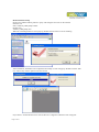
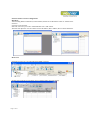
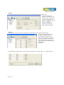
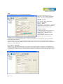
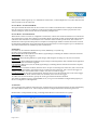
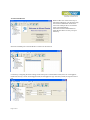
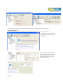
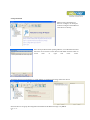
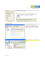
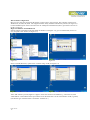
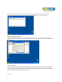
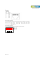
User Manual of Serial to WiFi Converter, Model VE10W
Wiring Architecture
RS232 Wiring Diagram
Serial
Signal VE10W
Device
Pin
Pin no’s
no’s
2
RX
3
3
TX
2
5
GND
5
7
RTS
8
8
CTS
7
Signal
TX
RX
GND
CTS
RTS
RS485 Wiring Diagram
Serial
VE10W Signal
Device Pin
Signal
no’s
D1
DD+
2
D+
RS422 Wiring Diagram
Serial
Device
Signal
RR+
TT+
VE10W
Pin
no’s
3
4
1
2
Signal
TT+
RR+
LED Indicators
SYS (Red)
LAN (Green)
TX (Red)
RX (Green)
: Power
: Network
: Data sent
: Data received
When the Power is on, the LED in ON
When the LAN signal is detected, the LED will be ON.
When data is sent out from the network, the LED will blink.
When data is received in the network, the LED will blink.
When you finish the steps mentioned above and the LED indicators are as shown, the converter is
installed correctly. You can use the Software Setup CD to setup the IP Address.
To proceed with the Advance parameter setup, you can also use a web browser (IE or Netscape) to continue
the detailed settings.
Page 11 of 18
DS Tool Software Setup
DS Tool uses UDP broadcast packets to query and configure converters on the network.
Insert the CD.
Select “DSTool_ODM_Setup” folder.
Double click
“DSTool_ODM_Setup.exe”.
When the “Installing DSTool” screen pops up, double click the “Start” icon for installing.
After installation, “Installation was completed successfully” screen will pop up. Double click the “OK”
icon. Choose any of the 2 options in the next screen.
If you choose “Launch DSTool Now” then the Device Configuration manual screen will appear.
Page 22 of 18
Serial to Wi-Fi Converter Configuration
Broadcast
After finishing DSTool installation, launch DSTool, double click “Broadcast” button. It will detect the
existence
converters in the network.
Select the converters you wish to add and double click “Add” button.
The table will depict the converter details such as IP address, MAC Address, Device Name and Status.
Device List
In the Device List icon, you will find all the added converters.
Double click on the device will allow you to configure other converter settings.
Page 33 of 18
General
After listing of device IP in “Device List” item, you can click the IP as shown in the table.
General information as
“Model”, “IP Address”, and
“MAC Address”, “Firmware
Version” “Device Name /
Location“ and device working
status … etc appear.
You can configure some
parameters and modify
device name and location
Security
Serial to Wi-Fi converter’s Security includes Access IP, Mask list and Administration security.
The Access IP Table specifies the
IP address and Subnet that can
access the device. The access is
based on IP and Mask combination.
If the access is open to all hosts, Do
NOT enable this function. You can
assign a password for Administrator’s
Management
& Security.
After modifying configuration, be sure to Save the changes by using “Apply Only” or “Apply and Save”.
Page 44 of 18
Networking
Serial to Wi-Fi converter can support both
type of IP such as Static IP or DHCP/BootP
IP configuration.
After modifying configuration click the
icon of “Apply Only” or “Apply and Save”
for finishing IP configuration.
Wireless
You can use the wireless item for
configuring Serial to Wi-Fi Converter’s
Wi-Fi parameters. “SSID Scan” is for
searching the available wireless access
point and to select your AP device.
“Wireless Encryption” is for setup
parameters as encryption type and key.
Save the changes by using “Apply Only”
or “Apply and Save”.
Notification
Serial to Wi-Fi
converter can support 3
ways of event
notification e.g “SNMP
Trap”, “Email
Notification” and
Syslog Notification.
Page 55 of 18
Management
In addition to DSTool, Serial to Wi-Fi Converter can also be managed by Web and Telnet consoles as well as by
SNMP.
The Web and Telnet functions are
enabled as default. To enable or
disable the management consoles,
you can use the “Configuration”
and “Management” of DSTool for
configuring.
To enable SNMP trap support, you
have to check the SNMP
Management Enable device and
specify SNMP settings including Community, Location, Contact, and Trap Server IP.
Upgrade Firmware
To update firmware of the device,
save the firmware file in your host
PC. Go to “Configuration”, and
“Update Firmware”. Specify the
file location by Browsing and
continue operation by Update. The
device will reboot after firmware
updating.
Note: All parameters will restore to default after the firmware update, except for the device IP address.
Save/Load
After finishing setup, click “Apply and Save” button.
The changes are valid after rebooting the device.
“Load default” is all parameters changes to factory’s default except network setting.
“Reboot Device” is for rebooting device and needs to broadcast again to search the device.
“Import” is for retrieving saved configuration file in to the current device.
“Export” is saving the current parameters onto a file and export to a current host for saving.
Page 66 of 18
Port
Port Configurations is for configuring Serial parameters.
Port Alias : Remarks for the port.
Baud rate : From 110bps to 460.8kbps
Parity : No, Even, Odd, Mark, Space
Data Bits : 5, 6, 7, 8
Stop Bits: 1, 2 (1.5)
Flow Control : None, XON/XOFF,
RTS/CTS, DTR/DSR
Interface : RS232
Performance : “Throughput” : guarantees
highest transmission speed or “Latency” :
guarantees shortest response time.
Delimiter Settings
For advanced data packing options, you
can specify delimiters for Serial to
Ethernet and / or Ethernet to Serial
communications.
You can define 4 delimiters (00~FF,
HEX) for each way and until the
delimiters are received the data will not be transmitted successfully.
“Flush Ethernet to Serial Data Buffer After” is time for which data will be stored before getting transmitted
between Ethernet and Serial.
“Force TX interval time” is for specifying the timeout when no data has been transmitted and the timeout is
reached or TX buffer is full (4K Bytes), the queued data will be sent. If you want to disable and the parameter is
setting “0”. (factory default)
Service Mode : UDP Mode
When device is configured as TCP Server, it gives the connected serial device a unique IP : Port address on a
TCP/IP network that it can be accessed by other host on the network. Device as TCP Server waits passively to
be contacted by the host computer, allowing the host computer to establish a connection and get data from the
serial device.
Page 77 of 18
This operation mode supports up to 5 simultaneous connections, so that multiple hosts can collect data from the
same serial device at the same time.
Service Mode : Virtual COM Mode
This option enables the Serial Port in the Converter to act and be controlled as PC’s COM port for Windows.
One PC can have as many as COM ports on the network without the limitation of PC’s physical slots. The
Virtual COM ports on the network can also be shared by multiple hosts.
Service Mode : TCP Client Mode
When Serial to Wi-Fi converter is configured as TCP Client, it allows the connected serial device to initiate the
TCP connection to remote host software when needed. When connected, the data is transmitted bi-directionally
and till the data transmission is finished, the TCP connection will be closed by TCP Client. The connect-ondemand TCP Client operation helps the host computer to manage high number of remote devices that exceeds
the maximum simultaneous TCP connections allowed. Serial to Wi-Fi converter supports up to 5 simultaneous
TCP Client connections for redundant system considerations
Notification
Port status can be notified to administrator by email, SNMP trap, or System Log.
Several events of notification include :
DCD changed: When DCD (Data Carrier Detect) signal changes, indicating the modem connection status has
changed, the event will be triggered.
RI changed: When RI (Ring Indicator) signal changes, indicating the incoming of a call, the event will be
triggered.
DSR changed: When DSR (Data Set Ready) signal changes, indicating that the data communication equipment
is powered off, the event will be triggered.
CTS changed: When CTS (Clear To Send) signal changes, indicating that the transmission between computer
and DCE can proceed.
Port connected: In TCP Server Mode, when the device accepts an incoming TCP connection, this event will be
trigger. In TCP Client Mode, when the device has connected to the remote host, this event will be trigger. In
Virtual COM Mode, when Virtual COM is ready to use, this event will be trigger.
Port disconnected: In TCP Server/Client Mode, when the device looses the TCP link, this event will be trigger.
In Virtual COM Mode, When Virtual COM is not available, this event will be trigger.
To enable activate the notification, specify the event type and the notification methods.
The details of SNMP trap Server, Email SMTP server, or Log server IP should be configured first properly in
device “Configuration” “Management”.
VCOM List
You can monitor the COM port status from the “VCOM” function. The monitored items can also be defined by
the “Select Monitor Items” icon. The COM ports must be configured first before monitoring the status.
DSTool offers 5 Setup Wizards to help you manage Serial Wi-Fi Converter devices as a group.
Page 88 of 18
Virtual COM Wizard
DSTool offers one of the easiest way to
add serial COM ports over the network by
the Virtual COM Wizard. Serial Wi-Fi
Converter COM port driver is installed
when you install DSTool.
Select the Virtual COM Wizard from
Setup Wizard. There are only 3 steps to
follow up.
Select the available ports of Serial Wi-Fi Converters on the network.
Continue by configuring the Serial settings of the Serial ports. In Performance mode, there are “Throughput”
mode and “Latency” mode. In Throughput mode, the throughput is high. In Latency mode, the response time is
low.
Page 99 of 18
Specify the Virtual COM port range and continue the operation by checking the COM port table
Serial Tunnel Wizard
The Serial Tunnel Wizard gives you the option to transparently pair two devices over the network.
Select the devices that should be
paired and move the devices into
IP1 and IP2.
After configuring the serial setting
of the ports, the serial tunnel will be
built by assigning one port as the
TCP Server mode and the other as
the TCP Client mode.
Page 1010 of
18
Group IP Wizard
When you have more than one
device to configure, use Group IP
wizard to configure all IP addresses
of the devices remotely.
Select Group IP Wizard after opening DSTool, or use Broadcast and find
more than one Converters on the network and double click the button of
“Click
here”
at
right
side
lower
corner.
Search the devices in local network (i.e. same subnet), or search by an IP range. Select the devices
Select the devices for group IP configuration and define the IP addresses range or by DHCP.
Page 1111 of
18
Click NEXT to confirm the setup and the IP configuration is finished, you will
see the IP addresses for the devices
Group Setup Wizard
Group Setup Wizard can help you to copy the
configuration of one device to other
converters. You can select the items to be
copied. Go to “Setup Wizard”, “Group Setup
Wizard”, and choose “Next” to continue.
Select device model as “Serial Server DS-11W”.
Page 1212 of
18
Select the Source device for the configuration and Destination devices.
Click NEXT to confirm and finish the wizard.
Page 1313 of
18
Group Firmware Wizard
To update firmware for a group of devices can
be as easy as 4 steps of Group Firmware
Wizard
Select the device model as Serial to Wi-Fi Converter DS-11W, and select available converters on the network for the
upgrade
Specify the firmware image and select NEXT. Confirm the firmware upgrade and continue operation. DSTool
will upgrade firmware of the converter and reboot again to finish
Page 1414 of
18
IP Collection
Dynamic DHCP IP settings find the changing IP addresses.
DSTool supports auto IP reporting
function to report the current IP
address of the Serial to Wi-Fi
converter units to administrator. To
enable the function, check “Auto IP
Report” in “Configuration”,
“General”. Specify the host that the
device should report IP to, or define
current host as the report host.
Be sure to define the Report
Interval time. Zero means disabled
Go to the IP Collection function of
the main menu and find the
converters auto IP report list
!!!!!!!!!!!!!!!!!!!!!!!!!!!!!
System Log
You can use a calendar at the button of
“System Log” screen for searching the
history data of log massages.
Page 1515 of
18
Web Console Configuration
Here you can verify the connections & settings. Connect a PC to the Converter. The operating system can be
Windows 95, 98, ME, XP, 2000. The “Hyper Terminal” utility should be installed on your PC (see Figure 4.1).
Connect the RS232 port of the Converter to the PC COM port & the Ethernet ( RJ45 ) port of the Converter to
the PC’s LAN port.
Hyper Terminal for TCP/IP WinSock
Initiate a Hyper Terminal from the Start Menu in Windows (see Figure 4.1), give a terminal name, choose an
icon, and press “OK” button (see Figure 4.2).
Figure 4.1
Figure 4.2
Select “TCP/IP (Winsock)” option at the “Connect using:” field (see Figure 4.3)
Figure 4.3
Figure 4.4
After “OK” button is pressed, Figure 4.4 appears. Enter the converter’s IP address (e.g. 192.168.0.10) at the
“Host address:” field and the Socket port number set for the Serial Port 1 at the “Port number:” field (e.g 4660).
(The Socket type of the Serial Port 1 should be “TCP Server”.)
Page 1616 of
18
After “OK” button is pressed, Figure 4.5 appears. If the Hyper Terminal connects with the converter
successfully, the time clock at the “left lower” corner “Connected hh:mm:ss” will start counting.
Figure 4.5
Hyper Terminal for COM Port
Initiate another Hyper Terminal as a COM Port Terminal (in Figure 4.3, select COM 1 or other COM port
instead of “TCP/IP (Winsock)”). Set the COM port Properties to be the same as those set for the Serial Port of
the converter.
Figure 4.6
Data Transmission
When all steps described above are finished, type any characters on the COM Port Terminal and check if the
typed characters are also displayed on the TCP/IP Winsock Terminal. Alternatively, check if the characters
typed on the TCP/IP Winsock Terminal are also displayed on the COM Port Terminal. If yes, then all settings
are correct and the converter can operate properly.
Page 1717 of
18
Pin outs
RS-232 Pin Assignment
The pin assignment scheme for a 9-pin male connector on a DTE is given below.
PIN 1 : DCD
PIN 2 : RXD PIN 3 : TXD PIN 4 : DTR
PIN 5 : GND
PIN 6 : DSR PIN 7 : RTS PIN 8 : CTS
PIN 9 : DC 5V
RS-422 Pin Assignment
The pin assignment scheme for a 4-pin RS-422 is given below.
PIN 1 : RPIN 2 : R+
1 2 3 4
PIN 3 : TPIN 4 : T+
Page 1818 of
18