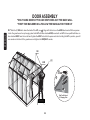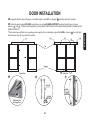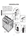
1
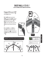
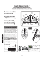
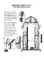
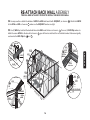
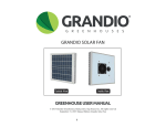
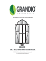
GRANDIO
®
G R E E N H O U S E S
2015 GRANDIO ELITE BACK WALL TRANSFORMATION KIT
Inside View
GRA-ELI-BD
BACK WALL TRANSFORMATION USER MANUAL
© 2013 Grandio Greenhouses, Backyard Living Source Inc. All rights reserved
2015 Manual Edition Back Wall Transformation Kit
GRANDIO
®
IMPORTANT! READ BEFORE BEGINNING ASSEMBLY
G R E E N H O U S E S
Dear Valued Customer,
We would like to congratulate you on your new
Grandio Greenhouse purchase. We are confident
that you have made the right decision in choosing Grandio. Our greenhouses are made with
high quality aluminium and polycarbonate and
will last for many garden seasons to come.
Please take the time to carefully read this
instruction manual for an easier and more
enjoyable assembly experience.
Cheers!
Grandio Greenhouses
THIS BACK DOOR TRANSFORMATION MANUAL IS FOR CURRENT GREENHOUSE OWNERS THAT ARE SWITCHING OUT
THEIR BACK WALLS ONLY.
SEE OPTIONS BELOW FOR FURTHER EXPLANATION.
OPTION 1 - 1ST TIME BUILDING GREENHOUSE KIT
You will discard this manual and use only the manual that came
with your greenhouse kit. Your manual included in your greenhouse kit will tell you how to build the back wall with a door.
Save this owner’s manual for future
reference and if you need our help.
CONTACT OUR CUSTOMER SERVICE
DEPARTMENT at:
1-866-448-8231
Hours: 8:30a.m.-5:00p.m. Monday through
Friday (Mountain Standard Time)
Backyard Living Source
9543 W. Emerald St., Suite 101
Boise, ID 83704
www.grandiogreenhouses.com
OPTION 2 - SWITCHING OUT EXISTING BACK WALL
You will use this manual to easily remove the back wall you currently have on your greenhouse and modify it with this kit to
create a new back door.
• Follow the step by step instructions.
• Only perform this switch out on a wind free or calm day.
• Inventory all parts with the parts list on page 26.
• You must have at least 2 people for assembly.
1
IMPORTANT! SAFETY INSTRUCTIONS
FAILURE TO FOLLOW THESE WARNINGS MAY RESULT IN SERIOUS INJURY OR
PROPERTY DAMAGE AND WILL VOID WARRANTY.
To ensure safety, do not attempt to assemble this product without following the instructions carefully. Check entire box and
inside all packing material for parts and/or additional instruction materials. Before beginning assembly, read the instructions and identify all parts using the hardware identifier and parts list on page 26. Complete assembly and
proper usage are essential to reduce the risk of accident or injury when using your Grandio Greenhouse.
CAUTION: Do not leave polycarbonate panels laying on grass or leave in the sun or extreme heat, keep in a cool
dry place until they are to be installed!! (May cause burning to plants or grass if left directly on top of them, also may
damage panels due to the protective film adhering to panels.) Panels may scratch easily. Do Not use solvent cleaners.
• Each of the polycarbonate panels have a clear film side that should always face the sun, and a white film side which faces inside.
The clear side has a UV coating and we recommend marking a small “x” on a corner of each panel to determine which side has the
UV Coating as you cannot visually determine with your eye in the case of future disassembly.
• Due to shipping, the grooves of some of the aluminum profiles may be too small to insert into the polycarbonate sheet, you may
carefully use a screwdriver to pry the framework open so the polycarbonate sheet can be inserted smoothly.
• Do not use or store hot objects such as grills, blow torches, welding equipment, etc. in or near your greenhouse.
• Do not allow children or pets to play in greenhouse or in the set up area until assembly is complete.
• If using a ladder during assembly, use extreme caution.
• A clean level surface is essential to maintaining the solid integrity of the structure, Install the base correctly as described in
manual. Please anchor the greenhouse down to a firm and level base.
NEEDED FOR ASSEMBLY
• Tape Measure
• 1 Step Ladder
• Level
• Work Gloves
• Carpenter Square
• Permanent Marker
• At Least 2 Adults
• Masking Tape
GRANDIO
• Safety Glasses
• Drill
• Knee Pads
• Folding Utility Table
2
TIP
When you see this icon
pay special attention to
the helpful tips we have provided that will
make installation more efficient.
GRANDIO GREENHOUSE
BACK DOOR KIT DIAGRAM
601B
DIAGRAM SHOWS THE ASSEMBLED
BACK WALL TRANSFORMATION OF THE
GRANDIO ELITE GREENHOUSE.
IMPORTANT: POLYCARBONATE PANELS
The UV-Protected side is covered with clear film and
must face toward the sun. The side covered in white film
will always face the interior of the greenhouse. We
suggest you peel all film off completely prior to assembly and use a permanent marker to place a small “X” on
the lower right corner of each panel on the clear side
that faces the sun, each panel has a sticker labeling the
panel number and this side always faces the sun or
outward as well. DO NOT REMOVE LABELS UNTIL
YOU INSTALL PANELS. The “X” is suggested in case
you dis-assemble your greenhouse in the future so you
may identify which side has the UV coating. Always use
gloves when handling the polycarbonate panels as the
edges can be very sharp.
630
Y3-1 Y3-2
603E
601B
Y2-1
L28
L08D
603C
604-L
601A-FL
Y1
L08A-X
606-WS
623A
630
603D
623A
622-L
Y6
622-R
Y6
622
622
620
620
Y6
Y6
623B
623B
619
Sun
Transparent Clear Film
Polycarbonate
Panels
601B
BACK
Outside View
Opal White Film
3
L21
601B
L28
Y2-2
L08D
603C
604-R
Y1
L08A-X
606-WS
601A-FR
GRANDIO
®
G R E E N H O U S E S
ASSEMBLY INSTRUCTION STEPS
PREPARE FOR ASSEMBLY
Introduction & Prepare For Assembly.............1
STEP ONE: DETACHING BACK WALL
Diagram of Assembled Back Door....................3
Safety Instructions...............................................2
Detaching Back Wall.........................................5-8
STEP TWO: BACK WALL DOOR ASSEMBLY
Back Door Assembly.......................................9-14
Attaching Back Door Wall..........................15-18
End Cap Installation...........................................19
STEP THREE: REATTACH BACK WALL
Door Assembly...............................................20-25
GRA-ELI-BD Parts List.......................................26
Warranty................................................................27
STEP FOUR: DOOR ASSEMBLY
STEP FIVE: PARTS LIST
4
Warning: Follow the directions for detaching back wall as shown here.
** This section will require a minimum of 2 people.
DETACHING BACK WALL INSTRUCTIONS
1.1 Detach all JG01, JG02A, JG02B, JG03A and JG03B end caps from the ridge, mid roof and gutters on both front and back
of your greenhouse as shown below. Set aside all end caps and hardware in a safe place for reinstallation later.
1.2 Detach the L28 from only the top L21 as shown, let it fall to the side out of the way of the endcaps on the side with the
doors. See .
603D
JG01
S04/
ML01
L21
L28
JG02B
STEP ONE
Top Left
Profile View
JG03B
JG02A
Z03
JG03A
Z03
5
DETACHING BACK WALL INSTRUCTIONS
YOU WILL NEED AT LEAST 2 PEOPLE TO REMOVE THE BACK WALL FOR SWITCH OUT
1.3 Slide 610 gutter piece out one panel section only, of 609’s groove as shown in diagram
Repeat on other side.
. Remove Y8 panel and Y7 panel.
1.4 Slide 630 out one panel section only of upper mid roof section to allow for removal of the Y11 panel see
side of greenhouse.
. Repeat on other
Y11
630
602B
630
Y8
630
602B
609
610
Y7
610
601B
610
609
6
STEP ONE
601A
DETACHING BACK WALL INSTRUCTIONS
YOU WILL NEED AT LEAST 2 PEOPLE TO REMOVE THE BACK WALL FOR SWITCH OUT
1.5 Loosen and remove the (2) of each L08E-X, L08D-X and the L08C-X off the back wall as shown in
.
1.6 Be sure one person is on the outside of the greenhouse holding and supporting the back wall as the person inside
detaches all back wall hardware.
1.7 Loosen the S04/ML01 screws that attach the 607 Roof Ridge to the back wall see
hold the 609 Eave and Mid Roof Support to the back wall as shown in
609
and
607
BZ-1
Inside View
609
L08D-X
607
S04/ML01
601B
L08E-X
CZ-1
.
. Loosen the S04/ML01 that
L08D-X
601B
CZ-1
609
L08C-X
L08C-X
Inside View
601B
STEP ONE
S04/ML01
601B
7
DETACHING BACK WALL INSTRUCTIONS
YOU WILL NEED AT LEAST 2 PEOPLE TO REMOVE THE BACK WALL FOR SWITCH OUT
1.8 Detach back wall 601A’s from back base corners by loosening S04/ML01 on both sides as shown in
.
1.9 Detach the (5) remaining W05 clips to release the back wall where the 601A’s meet the corner of the base as shown in
,
and where 602D’s, and the 602C meet the BA-S1 see
. You will need to replace S04/ML01’s on the back wall where the
W05 Clips were to keep the back wall together for removal. The back wall should be free from the middle section and base kit,
you and other person will want to gently pull apart and lay flat, with the outside facing down on a tarp. Begin disassembling the
back wall, keep pieces in their respective places to get ready for the back wall to door transformation assembly. Place all nuts,
bolts and hardware into a safe place such as a container with a lid.
601A
BA-S1
ML01
S04
BA-S2 or
BA-S6
Bac
k Ba
se
602C
602D
602D
W05
Inside View
W05
602C, 602D
Outside
Bac
kB
ase
STEP ONE
Inside
Base
8
BACK WALL DOOR ASSEMBLY
ALWAYS ASSEMBLE FRONT AND BACK HORIZONTAL
This picture shows the inside view of the back wall assembled for accepting a door.
All parts for this section will be found from the disassembled back wall and in the box GRA-ELI-BD
We recommend that you assemble the new back wall on a tarp.
601B
601B
We recommend watching
our how to assembly videos
with tricks and tips for easier assembly and
installation of your Grandio Greenhouse at:
www.grandiogreenhouses.com
GRANDIO
Y3-2
601B
603E
TIP
Y3-1
601B
603D
Y2-2
L08D
STEP TWO
603C
603C
L08A-X
604-L
Y1
Y1
619
Inside View
606-WS
9
BOLT INSTALLATION TIP:
Locate all nuts and bolts, pre
thread and place in the groove of the
extrusion to make installation easier. Move
up or down for exact placement.
GRANDIO
L08A-X
604-R
606-WS
TIP
Y2-1
L08D
601A-FR
Lay flat on ground to
assemble the front and back
frames of your greenhouse. Panels can burn
grass and plants if in direct light. Try to
assemble on a calm day in the shade.
GRANDIO
TIP
601A-FL
BACK WALL ASSEMBLY
ALWAYS ASSEMBLE FRONT AND BACK HORIZONTAL
2.1 Pre thread all S05 screws into the WG01
and WG02’s for ease of installation, see
only turn S05 a few turns.
S05
2.2 Use WG01 bracket to attach the (2)
WG01
601B
601B’s together with the 603E, secure parts
with the S05 screws provided see . The
WG01 will slide into the groove of the
601B’s, and also slide into the groove of the
603E, screw head will remain outside channel.
601B
WG02
603E
2.3 Install WG02’s into (2) 601B’s then
tighten S05 screws when extrusions are
completely tight see
. Note: the fat end of
the WG02 will always be on the bottom side
see
.
601B
PRETHREAD SCREWS TIP:
Locate all WG01, WG02,
and S05 screws, pre thread these to make
installation easier. Note that the fat end on
the WG02 will always face downward.
GRANDIO
TIP
WG01
WG02
601B
601B
WG02
603E
FAT
END
FAT
END
601B
WG02
10
WG01
WG02
STEP TWO
Inside View
IMPORTANT: Use only S05 Screws, other screws may damage frame.
601B
601B
BACK WALL ASSEMBLY
ALWAYS ASSEMBLE FRONT AND BACK HORIZONTAL
*IF USING THE MOISTURE CONTROL KIT YOU WILL USE IT NOW
2.4 Insert polycarbonate panels Y3-2 and
Y3-1 into place as shown in
.
2.5 Attach 603E and 603D with W04
and S04/ML01 fasteners as shown in
WG01
601B
WG02
WG02
603E
.
Y3-2
601B
2.6 Attach the 603D to the 601B’s
using the W04-1’s with the S04/ML01
fasteners on both sides as shown in .
W04-1
603D
STEP TWO
IMPORTANT: POLYCARBONATE PANELS
Sun
Polycarbonate
Panels
601B
Y3-1
W04-1
W04
Inside View
The UV-Protected side is covered with clear film and
must face toward the sun. The side covered in white film
will always face the interior of the greenhouse. We
suggest you peel all film off completely prior to assembly and use a permanent marker to place a small “X” on
the lower right corner of each panel on the clear side
that faces the sun, each panel has a sticker labeling the
panel number and this side always faces the sun or
outward as well. DO NOT REMOVE LABELS UNTIL
YOU INSTALL PANELS. The “X” is suggested in case
you dis-assemble your greenhouse in the future so you
may identify which side has the UV coating. Always use
gloves when handling the polycarbonate panels as the
edges can be very sharp.
Transparent Clear Film
601B
601B
S04
ML01
603E
W04
603D
W04
Opal White Film
11
W04-1
W04-1
603D
BOLT INSTALLATION TIP:
Locate ML01/S04 nuts and
screws, loosely pre thread into the W04 and
W04-1’s and place in the groove of the
extrusion to make installation easier.
GRANDIO
TIP
BACK WALL ASSEMBLY
ALWAYS ASSEMBLE FRONT AND BACK HORIZONTAL
2.7 View diagrams and attach the (2) 604’s and (2)
601A’s to the 619. Note the orientation of the 604’s,
also there are 4 different 601A’s (2) for the front and (2)
for the back with different hole placements. You will
need to drill the holes for the back section to match the
front holes. See diagram on this page. The 601A-FR and
the 601A-FL will have a hole at the top side and will
face to the ground during assembly or back of greenhouse, please drill 1/4” holes for your 601A-B’s to match
the 601A-FL and 601A-FR this will transform your back
wall for hanging the doors.
604-R
OUTSIDE
INSIDE
DRILL 1/4”
HOLES
OUTSIDE
601A-FL
OUTSIDE
601A-FR
DRILL 1/4”
HOLES
Inside View
INSIDE
INSIDE
shows where the corner pieces attach to 619.
619
shows where the door frame attaches to the 619.
BOLT INSTALLATION TIP:
Locate all nuts and bolts, pre
thread and place in the groove of the
extrusion to make installation easier. Move
up or down for exact placement.
604-L
INSIDE
OUTSIDE
GRANDIO
TIP
STEP TWO
TIP: If necessary you may use a
screwdriver to wedge behind the
bolt head. This prevents bolt from
falling into the track.
A
Make sure the hole on the
T I P 601A-FL and 601A-FR
face to the back of greenhouse for future
install of the L21 and L28 bracket that
holds the door header in place.
601A-FR
619
GRANDIO
ML01
604-R
ML01
S04
INSIDE DOOR FRAME
S04
12
INSIDE
619
Inside View
BACK WALL DOOR ASSEMBLY
ALWAYS ASSEMBLE FRONT AND BACK HORIZONTAL
2.8 Attach 606-WS to 619, this will hold the
polycarbonate panels in place. If it seems too
tight slide fingers or nut driver along edges,
gently stretching the 606-WS to allow room
for panels to fit .
Polycarbonate panel
OUTSIDE
606-WS
619
604-R
Y1
2.9 Insert Y1 polycarbonate panels into
place, make sure Y1’s slide completely into
606-WS as shown in .
Y1
601A-FL
601A-FR
2.10 Set (2) 603C’s atop the Y1 panels, then
606-WS
attach (2) L08D’s to the 603C’s, 601A’s and
604’s using S04/ML01 fasteners, make sure it
is snug with the tops of the Y1 panels, then
tighten fasteners. See .
STEP TWO
604-L
619
Inside View
606-WS
2.11 Insert the Y2-2 and Y2-1 polycarbonate
panels as shown in .
Y2-2
603C
L08D
GRANDIO
TIP
Polycarbonate
Panel
Transparent Clear Film
Outside Greenhouse
Sun
601A
S04/
ML01
604
L08D
Y1
601A-FR
13
L08D
L08D
603C
Opal White Film
Inside Greenhouse
Y2-1
604-R
603C
601A-FR 604-R
603C
Y1
604-L 601A-FL
BACK WALL DOOR ASSEMBLY
ALWAYS ASSEMBLE FRONT AND BACK HORIZONTAL
2.12 Move roof and front section together
WG02
601B
601A-FR
S05
601B
2.13 Attach the L08A-X to L08D and 604 to
square front section loosen S04/ML01
attached to the bottom of the (2) 604’s,
square the frame with carpenter square or use
a measuring tape to make sure corner measurements are the same, also check distance
across from the top of 601A’s, and also to the
bottom of the 601A’s across, make sure
distance is the same. Tighten L08A-X’s to hold
squareness as shown in .
Fat End
UP
603D
S04
ML01
604
603C
W04-2
603D
601B
W04-2
WG02
WG02
S05
S05
Y2-2
Y2-1
L08D
601A-FL
W04-2
Y3-1
Y3-2
L08D
S04
ML01
L08D
603C
603C
L08A-X
L08A-X
604-R
604-L
Y1
Y1
601A-FR
L08A-X
601A-FL
619
WG02
Profile View
14
STEP TWO
and align the WG02’s into the 601A’s, and the
W04-2’s into the 604’s. Insure a snug fit
between the WG02’s, 601B’s and 601A’s and
then tighten the S05 screws as shown in
.
Tighten the W04-2’s with the S04 /ML01 nut
and bolt as shown in
.
Inside View
RE-ATTACH BACK WALL ASSEMBLY
YOU WILL NEED AT LEAST 2 PEOPLE TO INSTALL THE BACK DOOR WALL
Warning: Proceed only if you are replacing a back wall on an existing greenhouse.
3.1 With no less than 2 people place the pre assembled back section on top of the base kit back. Have person (1) hold the back
vertically while the other attaches the back section 601A’s to the base using S04/ML01 fasteners as shown in
Person (1) must continue to hold up the back wall!
.
3.2 See diagram
for overview of back wall. Use the S04/ML01 screws to attach the 607 (Roof Ridge) to the back wall see
Use the S04/ML01 to attach the (4) 609’s (Mid Roof and Eave Supports) to the back wall as shown in
and
.
3.3 Attach L08E-X and L08D-X to the back roof wall as shown in
STEP THREE
One person must continue holding the back wall in place.
607
BZ-1
L08E-X
609
CZ-1
L08D-X
.
601A
609
ML01
S04
BA-S2 or
BA-S6
Inside View
BA-S1
607
S04/ML01
601B
601B
609
L08D-X
CZ-1
Inside View
Back Left side
609
L08C-X
L08C-X
601A
Inside View
601B
S04/ML01
601A
601B
or 601A
Interior Back Wall View
15
.
RE-ATTACH BACK WALL ASSEMBLY
YOU WILL NEED AT LEAST 2 PEOPLE TO INSTALL THE BACK DOOR WALL
3.4 You may need to re-attach the bottom of L08C-X to 602A and base kit with S04/ML01, as shown in
to the 601A and 609 as shown in
, make sure the S04/ML01 combos are tight.
. Attach the L08C-X
3.5 Use (2) W05 clips to attach the back wall where the 604’s meet the base as shown in
. Then use (2) W05 Clip combos to
, you will have to switch out the nut and bolt combos that were originally
attach the corner 601A’s to the base kit as shown in
used over to the W05 Clips for
and
.
Inside View
601A
601B
Sli
intode L0
pla 8C-X
ce
601B
L08C-X
S04
ML01
604
604
Bac
k Ba
se
W05
BA-S2
Inside View
601A
Inside View
BA-S1
ML01
S04
BA-S2 or
BA-S6
602A
604-R
L08C-X
ML01
601B
S04
609
S04/ML01
L08D or
L08B
L08C-X
Fro
nt
INSIDE DOOR FRAME
619
Sid
eV
iew
601A
16
STEP THREE
602A
RE-ATTACH BACK WALL ASSEMBLY
YOU WILL NEED AT LEAST 2 PEOPLE TO INSTALL THE BACK DOOR WALL
3.6 Attach the back door section 619 to the base using (3) S04/ML01 fasteners as shown in
, then attach the 619-BAR
threshold support to the inside of the 619 with (5) S19 self tapping screws included in the package, see .
STEP THREE
619-BAR Threshold Support
will attach with (5) S19 self
tapping screws from the inside
of greenhouse.
601A
604
1
601A
2
Ba
ck
Sid
619 Attaches to the
base kit with S04/ML01
eV
iew
BA-S1
17
BACK WALL PANEL ASSEMBLY
3.7 Insert Y11 panels into the upper roof sections of your greenhouse as shown, then slide the 630’s back into place to lock the
panels into place see
.
3.8 Slide Y7 and Y8 panels into place as shown below, then slide the 610 gutter back into place to lock those panels into place
. Repeat on other side.
630
602B
Y11
630
Y8
630
610
Y7
610
601B
610
Fro
nt
Sid
eV
iew
609
601A
18
602B
609
STEP THREE
see diagram
MIDDLE ASSEMBLY INSTRUCTIONS CONTINUED
4.25 Attach JG01, JG02A, JG02B, JG03A and JG03B end caps to the ridge, midroof
and gutters on both front and back as shown below. Use Z03 screws to attach the
JG03A and JG03B endcaps along with the silicone adhesive. Use Z06 screws to fasten
end caps through the WG01 and WG02 as shown in images. Note you may want to seal
into place with silicone caulk on the inner side and around the edges.
JG02B
JG01
Exterior view of mid roof cap JG01.
STEP THREE
JG03B
Z03
Interior greenhouse view of mid roof cap, where Z06
screw goes through WG01 mid hole into the end cap.
JG02A
Z06
JG03A
Z03
19
DOOR ASSEMBLY DIAGRAM
This image shows the inside view of Right Door Assembly.
All parts for door assembly will be found in box GRA-ELI-BD.
Use the #2 head Phillips Screw Driver for installation.
623A
622
Side View
Z01
Y6
623A
Side View
622-R
UP
Z01
622
UP
Double
Ball Catch
620
Y6
620
Z01
STEP FOUR
622-R
Z01
UP
UP
Z01
623B
623B
Z01
J08A
Bottom
View
Inside View
622
Bottom
View
622
J08A
J08A
J08A
20
STEP FOUR
DOOR ASSEMBLY
We recommend you lay out all parts for both doors to make sure they match up correctly for hanging. Double check the orientation of what is inside verses outside and how the doors will hang on page 23-25. Make sure window panels face the right direction
to the sun and note that the panels have pre drilled holes for the handles to attach later and these need to be aligned with the
lock mechanisms, you may have to re drill these holes out if they are not apparent. This will save you from assembling the wrong
way. Be careful not to strip the phillips heads when assembling.
4.1 Insert J08A into the bottom of the 622, note the bottom groove is smaller than the top groove of 622, see .
4.2 Use the Z01 screws to attach the 622 to the 623B, 623A and 620 as shown in .
4.3 Insert Y6 windows into position as shown in .
623A
623A
623A
FLUSH
ALIGN
WITH TOP
Z01
You may need to gently open
the channel with a flat head
screwdriver if screws are not
going into place with ease.
622
Side View
622
Z01
622
620
620
UP
Y6
623B
Z01
UP
Bottom
View
J08A
620
Y6
623B
623B
Inside View
622
GRANDIO
TIP
Transparent Clear Film
Outside Greenhouse
J08A
Polycarbonate
Panel
21
Opal White Film
Inside Greenhouse
Sun
DOOR ASSEMBLY
4.4 Insert J08A into the bottom of the 622-R and 622-L, note the bottom has a groove see .
4.5 Attach the 622-L to the 623B, 623A and 620 using the Z01 screws as shown in .
4.6 Follow the same instructions for the other door making sure that the 622-L and 622-R with the double ball catch match up
.
STEP FOUR
so doors will latch closed and slide properly
Z01
Side View
Of Top
622-L
* Double
Ball Catch
on the 622-L
623A
Side View
Of Top
622-R
Double
Ball Catch
622-R
* Note the orientation of
the 622-L and 622-R.
Also make sure the right
side is facing out on the
Y6 polycarbonate panels.
UP
* Double
Ball Catch
on the 622-R
UP
Y6
UP
Z01
620
622
UP
Side View
Of Bottom
Bottom
View
J08A
622
Side View
Of Bottom
Y6
622
Z01
623B
Inside View
J08A
22
DOOR ASSEMBLY
*ONLY HANG DOORS IF YOU ARE SWITCHING OUT THE BACK WALL
*FIRST TIME BUILDERS WILL FOLLOW THE MANUAL FOR THEIR KIT
STEP FOUR
4.7 Slide the (2) S02 bolts down the track of the L21, see
. Align with the holes on the 603D door header. With one person
inside the greenhouse line up hanging door track L21 with door header 603D, move bolts on L21 to line up with bolt holes on
door header 603D. From the inside hand tighten the ML01 nut while the person outside is holding the L21 in position, you will
now center on the front of the greenhouse and tighten the S02/ML01 combo.
S02
603D
L21
S02
SCREW
1
ck
a
Tr
2
2
Inside View
Side Profile View of
L21 Hanging Track
23
DOOR INSTALLATION
4.8 Separately slide the top of the doors in the left and right side of L21, see diagram
, until they latch in the middle.
below in
, and
. If holes are not apparent you may need to drill holes into the polycarbonate panels to allow for the
handles to attach.
**We included some felt dots in your package, please apply to the inside bottom edge of the 623B as shown in , these felt dots
will make your doors fit snug and slide smoothly.
L21
S04
S02
Top
Bottom
Outside View
Inside View
622-HNDL
622-HNDL
Inside View
622-HNDL
NUT/BOLT
Side Profile View
of Hanging Track
24
622-HNDL
NUT/BOLT
L21
S04
STEP FOUR
4.9 Attach the door handles 622-HNDL to both doors using the 622-HNDL-NUT/BOLT provided to both doors as shown
STEP FOUR
DOOR INSTALLATION
4.10 Attach L28 to L21 with S04/ML01, and L28 to
601A with S02/ML01 as shown below in diagram
and
. Check that the L21 and L28’s are square. Attach
(2) J07 to the ends of L21 see
. The L28 should align
square to the 601A. Repeat on the front L28 you may
have loosened in the beginning. Reattach the L28 on
the other end also.
603D
4.11 Check that the door locks are snug, you may adjust S04/ML01
L21
them with screwdriver if needed as they may be tightened or loosened.
L28
Top Left
Profile View
J07
Backside View
601A-FR
L21
601A
S02
L28
S02
Ba
ck
Sid
eV
iew
ML01
L28
601A-FL
Top Profile View
25
601A
GRAPHIC
PART NAME
SIZE/LOCATION
QUANTITY
603D
72 3/16 in / 1833 mm
SIZE/LOCATION
QUANTITY
1
Z01
M4*30
SCREWS FOR DOORS
13
603E
18 1/4 in / 463 mm
1
ML01/S04
M6*10
35
70 3/4 in / 1797 mm
1
ML01/S02
M6*20
4
604L
70 3/4 in / 1797 mm
1
L21
95 1/2 in / 2425 mm
1
L08D
24 3/16 in / 614 mm
2
J07
L21 ENDCAP
2
619
619-BAR
S19
94 1/4 in / 2394 mm
51 3/16 / 1300
M4*10
1 - 619
1 - 619 Bar
5 - S19 Screws
L28
19 9/16 in / 497 mm
FRONT RIGHT
2
622
69 11/16 in / 1770 mm
2
W04
CONNECTOR BRACKET
1
622R
69 11/16 in / 1770 mm
1
W04-1
FRAME CONNECTOR
2
622L
69 11/16 in / 1770 mm
1
W04-2
FRAME CONNECTOR
2
620
21 7/16 in / 545 mm
2
Y3-1
UPPER ROOF PANEL
1
623A
21 7/16 in / 545 mm
2
Y3-2
UPPER ROOF PANEL
1
623B
21 7/16 in / 545 mm
FRONT RIGHT
2
Y2-1
BACK WALL SIDE
L08A-X
52 1/4 in / 1327 mm
CROSS SUPPORT
2
Y2-2
BACK WALL SIDE
1
J08A
DOOR
4
Y6
DOOR PANELS
4
622-DOOR
HANDLES
DOOR HANDLES
4
1/4 DB
1/4” DRILL BIT
1
604R
BACK WALL
BACK WALL
FRONT RIGHT DOOR
FRONT LEFT DOOR
GRAPHIC
26
PART NAME
1
STEP FIVE
(GRA-ELI-BD) GRANDIO ELITE BACKDOOR PACKING LIST
Grandio Greenhouse Limited Lifetime Warranty
1. Grandio Greenhouses are warranted to the original purchaser to be free from defects in material or workmanship for ten years from the
date of original retail purchase on all plastic panels. Additionally the aluminium frame is warranted for life. The word “defects” is defined as
imperfections that impair the use of the product.
2. Defects resulting from misuse, abuse or negligence will void this warranty. This warranty does not cover defects due to improper installation, alteration or accident. This warranty does not cover damage caused by vandalism, rusting, “acts of nature” or any other event beyond the
control of the manufacturer.
3. This warranty is nontransferable and is expressly limited to the repair or replacement of defective product if the product is defective within
the terms of this warranty, Grandio Greenhouses will repair or replace defective parts at no cost to the purchaser. Shipping charges to and
from the factory or distribution center are not covered and are the responsibility of the purchaser. Labor charges and related expenses for
removal, installation or replacement of the greenhouse or its components are not covered under this warranty.
4. This warranty does not cover scratching or scuffing of the product that may result from normal usage. In addition, defects resulting from
intentional damage, negligence, unreasonable use will void this warranty.
5. Liability for incidental or consequential damages is excluded to the extent permitted by law. While every attempt is made to embody the
highest degree of safety in all equipment, freedom from injury cannot be guaranteed. The user assumes all risk of injury resulting from the use
of this product. All merchandise is sold on this condition, and no representative of the company may waive or change this policy.
6. This product is not intended for institutional or commercial use; Grandio Greenhouses does not assume any liability for such use.
7. This warranty is expressly in lieu of all other warranties, expressed or implied, including warranties of merchantability for use to extent
permitted by Federal and State Law. Neither Grandio Greenhouses nor any representative assumes any other liability in connection with this
product. This warranty gives you specific legal rights, and you may also have other rights that vary from state to state.
27
NOTES
NOTES
GRANDIO
®
G R E E N H O U S E S
2015 Model Grandio Elite Back Door Kit
GREENHOUSE USER MANUAL
KEEP IN A SAFE PLACE FOR REFERENCE
CONTACT US IF YOU NEED HELP
OR
HAVE MISSING OR DAMAGED PARTS
GRANDIOGREENHOUSES.COM
BACKYARD LIVING SOURCE, INC.
9543 W. EMERALD ST., SUITE 101
BOISE, ID 83704
1-866-448-8231