Transcript
DN060-02v02
Capacitance Meter Manual
Features
l
l
l
l
l
l
About 1% accuracy. No calibration needed.
Measuring range: 1pF - 500µF
Automatic range select
Zeroing available
Real time serial output of measurement read-outs with time stamp
Low cost and easy to build
How to assemble
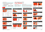
It is pretty straightforward to assemble the cap meter. Install all parts included in the kit onto the PCB by
following schematic and labels. Double check to ensure no soldering errors. If every thing ok then the cap meter
can be powered up and put into use. No adjustment needed.
How to Use
Measurement:
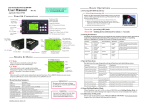
Insert the capacitor to be tested into J5. Capacitance will be displayed. Alternatively caps not fitting
into J5 can be connected through J3 with a pair of clips. Usually large caps take longer to show results
but should not longer than 2 seconds.
Zeroing:
Remove cap (if any) from J5 and J3. Press the “ZERO” button. “C0 ” will display. Wait for it to
disappear. Now the stray capacitance is compensated. The compensation value is stored in EEPROM
and will remain in effect until another zeroing is performed. To obtain good measurement results for
small capacitance shielding is required. To do this put the board into a metal box and connect
the ground of the meter to the enclosure.
Serial Data Format:
The ASCII outputs from TXD pin of J4 include sequence number, measurement time (in seconds), and
measured capacitance. The baud rate is 38.4Kbps fixed. The data format is 8 data bits, 1 stop bit, and
no parity.
Specifications
Error:
Range:
Power Supply voltage:
< 2%
1pF –500µF
8 –16 DC
Power Supply current:
<30mA
Revision History
Version
Date
Descriptions
01
2008.09.17
First created
02
2008.11.28
Modified for 109-06000-00B PCB. Removed reworking instructions since errors in
previous PCB had been corrected.
今越电子制作
-1-
www.jyetech.com
