1
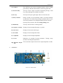
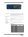
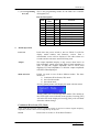
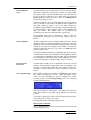
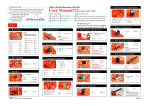
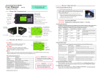
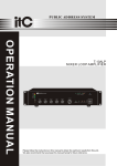
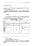
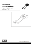
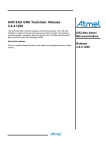
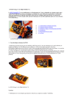
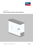
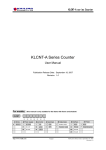
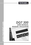
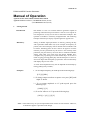
DN085-01v03
FG085 miniDDS Function Generator
Manual of Operation
Applicable Models: 08501, 08501K, 08502K, 08503, 08503K
Applicable Firmware Version: 1 ) 113-08501-100 or later (for U5)
2 ) 113-08502-030 or later (for U6)
1.
Getting Started
Introduction
The FG085 is a low cost versatile function generator capable of
producing continuous/swept waveforms* and servo test signals. It
was designed as an easy-to-use tool for electronic hobbyists. The
operation of FG085 is extremely straightforward. The following
examples will lead you step-by-step through some typical uses.
Data Entry
Setting of FG085 signal parameters is done by pressing the key
with a parameter label under it (F/T, for example, for frequency or
period). The current display will be cleared and an underline will
be shown, indicating place for new value to be typed in. If at the
moment you hit a parameter key the cursor is not currently at the
parameter just press the key one more time to make the underline
shown. Then enter new value using the DATA ENTRY keys.
Complete entry by hitting one of the UNITS keys. If an error is
made at typing pressing [ESC] key will do backspace to correct it.
If no more digits left when [ESC] is pressed it will exit Data Entry
and display the previous value.
A cursor focused parameter may also be adjusted incrementally by
tuning [ADJ] (rotary encoder).
Examples
1 ) To set output frequency to 5KHz press the following keys:
[F/T] [5] [KHz]
2 ) To change output waveform to square wave press [WF] until
“SQR” is shown.
3 ) To set output amplitude to 3V peak-to-peak press the
following keys:
[AMP] [3] [V]
4 ) To set DC offset to -2.5V press the following keys
[OFS] [+/-] [2] [.] [5] [V]
Note: * This feature may not yet be implemented with current version firmware. However,
its hardware support is provided in the design.
JYE Tech
-1-
www.jyetech.com
DN085-01v03
2.
Front Panel Features
Front view of 08501/08502
Front view of 08503
1 ) Power Switch
The power switch turns the FG085 on and off.
2 ) Parameter Keys
The parameter keys select the parameter to be entered. If cursor
is not currently at a parameter pressing the parameter key will
first move cursor to that parameter.
3 ) Data Entry Keys
The numeric keypad allows for direct entry of the FG085’s
parameters. To change a parameter value simply press the
parameter key (if cursor is not currently at the parameter press the
parameter key twice) and then type a new value. Entries are
terminated by the UNITS keys. If an error is made at typing press
[ESC] key to correct it (back space). If no more digits left when
[ESC] is pressed it will exit Data Entry and display the previous
value.
The [+/-] key may be pressed at any time during numeric entry.
JYE Tech
-2-
www.jyetech.com
DN085-01v03
4 ) Unit Keys
The UNIT keys are used to terminate numeric entries. Simply
press the key with the desired units to enter the typed value.
5 ) Waveform Key
This key selects output waveform. Repeated pressing of this
key will go through all available waveforms.
6 ) ESC key
This key back space typed digits and/or exit current state.
7 ) Rotary Encoder
Rotary encoder can incrementally adjust a focused parameter
up and down. To do this first pressing a parameter key to move
cursor the parameter to be changed and then turn the encoder.
Pressing rotary encoder will enter Setting Change state.
3.
8 ) MODE Key
This key selects FG085’s working modes.
9 ) Frequency (Period)
Display of current output frequency or period.
10 ) Waveform
Display of current waveform type.
11 ) DC Offset
Display of current output DC offset.
12 ) Amplitude
Display of current output amplitude.
13 ) Cursor
Indication of currently focused parameter. Turning rotary
encoder will change this parameter.
14 ) Function Output
(J4)
This is the front output connector. Its output impedance is 50Ω.
Connectors
Front view of 08501/08502
JYE Tech
-3-
www.jyetech.com
DN085-01v03
Board view of 08503
1 ) Power Input (J1)
This is the DC power supply input connector. Its center core
should be connected to the positive pole of power supply.
FG085 is specified for 14V DC. The current capacity of power
supply should be greater than 200mA average.
2 ) Function Output
(J5)
This is the back output connector. Its output impedance is 50Ω.
3 ) USB (J10)
This provides a connection to PC for waveform data download
and instrument control.
4 ) Alternative USB
(J7)
This connector allows wiring the USB connection to socket at
enclosure.
5 ) Contrast
Adjustment
This is a resistor trimmer for LCD contrast adjustment.
6 ) U5 Programming
Port (J8)
This is the programming header for the main controller
ATmega168 (U5).
Pin-out Description
Pin#
1
2
3
4
5
6
7
8
9
10
JYE Tech
Signal
Name
MOSI
+5V
NC
nRST
SCK
GND
MISO
GND
-4-
I/O
I
PWR
I
I
PWR
O
PWR
Function
U5 programming
No connection
Reserved
U5 programming
Reserved
U5 programming
U5 programming
www.jyetech.com
DN085-01v03
7 ) U6 Programming
Port (J6)
This is the programming header for the DDS core controller
ATmega48 (U6)
Pin-out Description
Pin#
1
2
3
4
5
6
7
8
9
10
4.
Signal
Name
MOSI
+5V
nRST
SCK
GND
MISO
GND
I/O
I
PWR
I
I
PWR
O
PWR
Function
U6 programming
Reserved
Reserved
U6 programming
Reserved
U6 programming
U6 programming
FG085 Operations
Power-on
Push down the power switch to turn on FG085. It will first
display model number and firmware version. Then a
customizable screen will be displayed. This takes about two
seconds and the unit enters normal working state.
Output
The output amplitude display is only correct when load is in
high impedance (much larger than 50Ω). If load impedance is
close to 50Ω the oupput amplitude will be lower then
displayed. If load impedance is 50Ω the output amplitude
will half of that displayed.
Mode Selection
FG085 can work in one of three different modes. The three
modes are:
1) Continuous Waveforms (CW) mode
2) Servo Position mode
3) Servo Run mode
Pressing [Mode] button will display the mode selection menu.
Tuning [ADJ] will scroll through these modes. The number at
the lower-right corner indicates menu position. Pressing [WF]
will select the mode displayed. Pressing [ESC] will exit Mode
Selection without change.
Continuous Waveform (CW) Mode
In this mode the generator outputs continuous signal of various waveforms. Signal frequency,
amplitude, and DC offset can be independently set by user.
Screen
JYE Tech
Please refer to Section 2 “Front Panel Features”.
-5-
www.jyetech.com
DN085-01v03
Waveform Selection
Waveform selection is done by pressing [WF] key.
Frequency
Frequency is set by first pressing [F/T]. The current display will
be erased and an underline is shown, allowing user to enter new
value. New value is entered with Data Entry keys and followed
by one of the Unit keys. Alternatively, frequency can be
changed incrementally by using the rotary encoder when it is
focused.
Frequency can also be set in period. Press [F/T] key will toggle
between frequency and period entry mode.
Frequency Range
In spite of that no limited range is set for frequency entry it
should be aware of that there are practical ranges for output
frequency due to the low resolution 8-bit DAC and slow sample
rate (2.5Msps). Out of these ranges signal quality will degraded
as larger distortions and jitters appear. The acceptable ranges
depend on actual applications. For FG085 output frequency
within following range is reasonably good for most
applications.
Function
Sine
Square
Triangle
Ramp
Staircase
Amplitude
Range
0 – 200KHz
0 – 10KHz
0 – 10KHz
0 – 10KHz
0 – 10KHz
Amplitude is set by first pressing [AMP] key. The current
display will be erased and an underline is shown, allowing user
to enter new value. New value is entered with Data Entry keys
and followed by one of the Unit keys. Alternatively, amplitude
can be changed incrementally by using the rotary encoder when
it is focused.
The displayed amplitude value is peak-to-peak value.
The amplitude range is limited by the DC offset setting since
|Vac peak| + |Vdc| ≤ 10 V (into High-Z).
D.C. Only
The output of the FG085 can be set to a DC level by entering
amplitude of 0V. When the amplitude is set to zero the A.C.
waveform will be completely shut off and the FG085 may be used
as a DC voltage source.
DC Offset
JYE Tech
DC offset can be set by first pressing [OFS] key. The current
display will be erased and an underline is shown, allowing user
to enter new value. New value is entered with Data Entry keys
and followed by one of the Unit keys. Alternatively, offset can
-6-
www.jyetech.com
DN085-01v03
be changed incrementally by tuning [ADJ] when it is focused.
In general, the DC offset may range between ±5V, but it is limited
such that |Vac peak| + |Vdc| ≤ 10 V (into High-Z), or | Vac peak | +
|Vdc| ≤ 10 V (into HIGH-Z).
Increment and
Decrement
FG085’s output frequency, amplitude, and DC offset can be
changed incrementally up and down by using the rotary
encoder. To do this first move cursor to the parameter you want
to change by pressing a parameter key and then turn the rotary
encoder clock-wise for increment and counter-clock-wise for
decrement.
Servo Position Mode
In this mode the generator outputs servo control signal with specific pulse width,
amplitude, and cycle. All these parameters can be set independently by user.
Servo Control Signal
The drawing below shows a servo control signal.
Typically servo signal takes following parameters:
1) Cycle: 20ms
2) Pulse Width: 1ms – 2ms
3) Pulse Amplitude: 5V
The pulse width determines servo position.
Screens
JYE Tech
The photo below shows the screens of Servo Position Mode.
The first screen shows pulse width in unit of microsecond. The
second shows pulse amplitude in unit of volt. Pressing [F/T]
will display the pulse width screen and pressing [AMP] will
display the amplitude screen.
-7-
www.jyetech.com
DN085-01v03
Pulse Width and
Cycle
At pulse width screen pressing [F/T] will erase current display
and show an underline, allowing user to enter new pulse width.
New pulse width is entered with Data Entry keys and followed
by one of the two Unit keys. The value entered is treated as
microsecond if the unit key [Sec] is used, or as millisecond if
the unit key [mSec] is used.
Please note that the range of pulse width that user can actually
enter is limited by two values, SV.PWmin and SV.PWmax. If
the pulse width you input is out of the range defined by
SV.PWmin and SV.PWmax then the input will be substituted by
the limit numbers. These limiting values can be modified by
user (see below). The default values of SV.PWmin and
SV.PWmax are 1000 uSec and 2000 uSec respectively.
Servo signal cycle can be changed too. This is done by
modifying the setting SV.Cycle in Setting Change state (see
below).
Pulse Amplitude
At pulse amplitude screen pressing [AMP] will erase current
display and show an underline, allowing you to enter new pulse
amplitude. Enter new pulse amplitude with Data Entry keys and
follow by one of the two Unit keys. The number you entered is
treated as volt if the unit key [V] is used, or as mill volt if the
unit key [mV] is used.
Like pulse width the maximum of amplitude that user can enter
is limited by the value of SV.AMPmax. If the amplitude entered
is greater than SV.AMPmax then the input will be substituted
by SV.AMPmax. The default value of SV.AMPmax is 5.0V. It
can also be changed in “Change Setting” state (see below).
Increment and
Decrement
At either pulse width screen or amplitude screen user can turn
[ADJ] to incrementally change pulse width or amplitude. The
step size of incremental change for pulse width is defined by
SV.PWinc, another setting that can be modified by user (see
below).
Servo Signal Settings
Servo signal settings are a number of EEPROM stored values
that affect the behaviour of servo signal generation. These
values are user changeable. In order to change these values
pressing [ADJ] to enter Setting Change state. The following
screen will be displayed.
The top line shows a setting name. The bottom line shows its
value. The number at top-right corner indicates current menu
position.
To change a setting first scroll to that setting by turning [ADJ].
Then press [F/T] to enter a new value.
Pressing [ESC] will exit Setting Change state.
Restore factory default
Factory default settings can be restored by scroll to the last item
and pressing [WF] key.
JYE Tech
-8-
www.jyetech.com
DN085-01v03
The following table lists the details about servo signal settings.
Setting
Descriptions
SV.PWmin
SV.PWmax
SV.PWmid
SV.PWinc
SV.RunStep
SV.RunRate
SV.Cycle
SV.AMPmax
The minimum pulse
width allowed
The maximum pulse
width allowed
Pulse width
corresponding to
servo nurture position
[ADJ] step size in
Servo Pos mode
Step size of pulse
width change in Servo
Run mode
Duration of one step
in Servo Run mode
Servo signal cycle
The maximum pulse
amplitude allowed
Acceptable
Range
0 – 26000 uSec
1000
0 – 26000 uSec
2000
0 – 26000 uSec
1500
0 – 26000 uSec
100
0 – 26000 uSec
100
0 – 6.5 Second
0.1
0 – 26000 uSec
20000
0 – 10.0V
5.0V
Default
When a setting is set to a value out of acceptable range the
instrument behaviour is not defined.
Servo Run Mode
In this mode the generator outputs servo control signal with changing pulse width. The
pulse width change step, rate, and range are user settable.
States
When Servo Run mode is first entered it stays at Ready state.
In this state a constant signal with pulse width equal to
SV.PWmin is generated.
When [WF] button is pressed it transfers to Running state.
In this state pulse width will change from SV.PWmin to
SV.PWmax incrementally in step defined by SV.RunStep. Once
it reaches SV.PWmax it will immediately change in the reverse
direction, i.e. from SV.PWmax to SV.PWmin incrementally
with the same step size. Pulse width will vary in this way until
[WF] key is pressed.
When [WF] key is pressed in Running state the generator will
enter Hold state, where pulse width stops varying and
maintains the value at the moment [WF] key is pressed.
JYE Tech
-9-
www.jyetech.com
DN085-01v03
Change Settings
5.
Settings that affect Servo Run mode behaviour include
SV.PWmin, SV.PWmax, SV.RunStep, and SV.RunRate. These
settings can be changed by user. Please refer to paragraph titled
“Servo Signal Settings” above for details.
Customizable Power-up Screen
At powering-up a customizable screen is displayed after model and firmware information is
shown. This screen contains 32 characters that can be defined by sending a string to FG085
via USB connection from a PC.
To do this you need
1) A PC serial communication application
2) A miniUSB-B cable that connects FG085 to a PC USB port
3) Select appropriate port and set communication format to “115200, n, 8, 1”
4) When FG085 is in normal working state (regardless modes) send a string in the
format that is started with “Z#=”, immediately followed by 32 ASCII characters
you want to display and ended by “#”. The string looks like this:
Z#=[ 32 ASCII characters ]#
5)
6.
When the sending is successful you will get a character “G” returned. Otherwise
you may get “?” or nothing.
Verify by powering off the unit and power up again.
Firmware Upgrading
From time to time there may be a need to upgrade firmwares in order to add features or
improve performance. FG085 contains two AVR micro-controllers from Atmel:
1)
ATmega168PA (U5), which is the main controller of the instrument.
2)
ATmega48PA (U6), which is the DDS core.
To upgrade firmware an AVR programmer with compatible programming header is required.
For programming header pin-out please refer to drawings under section “Connectors”. If the
programming header you have has a different pin-out. You need to re-route the signals to
make them match. (JYE Tech’s USB AVR Programmer [PN: 07302] is ideal for FG085 programming.
Please visit www.jyetech.com for details.)
Download updated firmware files from JYE Tech website (www.jyetech.com) and follow
instructions of the programmer you have to carry out firmware upgrading.
About Fuse Bits
AVR micro-controllers contain some fuse bits that configure the chip for specific applications.
In most cases these fuse bits should not be touched at firmware upgrading. But if somehow
these bits are changed they should be restored as follows.
1)
ATmega168PA (U5)
Extended Fuse Byte: 0b00000111
2)
High Fuse Byte: 0b11010110
( 0xD6 )
Low Fuse Byte: 0b11100110
( 0xE6 )
ATmega48PA (U6), which is the DDS core.
Extended Fuse Byte: 0b00000001
JYE Tech
www.jyetech.com
( 0x07 )
( 0x01 )
High Fuse Byte: 0b11010110
( 0xD6 )
Low Fuse Byte: 0b11100000
( 0xE0 )
- 10 -
DN085-01v03
7.
Technical Support
For any technical issues or questions in using the instrument please contact JYE Tech at
[email protected]. Or post your questions at JYE Tech forum at
http://forum.jyetech.com.
8.
Specification
Ø
Ø
Ø
Ø
Ø
Ø
Ø
Ø
Ø
Ø
Ø
Ø
Frequency range: 0 – 200KHz (Sine)
Frequency resolution: 1Hz
Frequency accuracy: 100 ppm
Period resolutions: 1ms
Amplitude range: 0 – 10V peak-to-peak
D.C. offset range: -5V – +5V
Waveform memory length: 256 bytes
Sample rate: 2.5Msps
Output impedance: 50 ohm
Power supply voltage: 14V DC
Current consumption: < 150mA (without loading)
Circuit board size: 155mm X 55mm
JYE Tech
www.jyetech.com
- 11 -