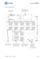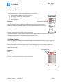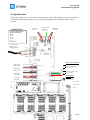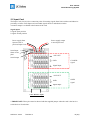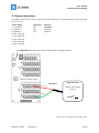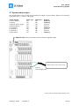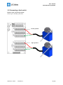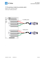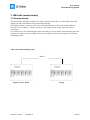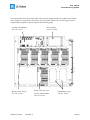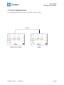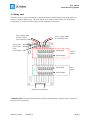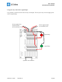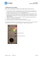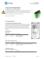
1
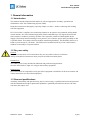
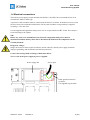
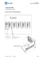
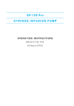
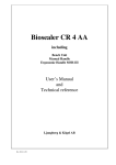
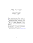
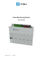
Valve Monitoring System User manual Article no: 74514 Revision: 4 User manual Valve Monitoring System Article no: 74514 Revision: 4 2 (22) User manual Valve Monitoring System Contents 1. General information ............................................................................................. 4 1.1.Introduction ..................................................................................................................................................... 4 1.2 For your safety ................................................................................................................................................ 4 1.3 Personal qualifications .................................................................................................................................... 4 1.4 Electrical connections ..................................................................................................................................... 5 2. Standard VMS ....................................................................................................... 6 2.1 System overview .............................................................................................................................................. 6 2.2 System Monitor ............................................................................................................................................... 8 2.3 Valve Monitor.................................................................................................................................................. 8 2.4 System Card .................................................................................................................................................... 9 2.5 Input Card ..................................................................................................................................................... 10 2.6 System alarm input ....................................................................................................................................... 11 2.7 System alarm output ..................................................................................................................................... 12 2.8 Connecting a limit switch ............................................................................................................................. 13 2.9 Connecting an inductive proximity switch .................................................................................................. 14 3. VMS with remote display ................................................................................... 15 3.1 Remote display .............................................................................................................................................. 15 2.2 Custom designed panels................................................................................................................................ 17 3.3 Relay card ...................................................................................................................................................... 18 4. Starting up the system ....................................................................................... 20 5. Service and troubleshooting ............................................................................. 21 5.1 Maintenance of UPS batteries ...................................................................................................................... 21 5.2 Troubleshooting ............................................................................................................................................ 21 5.3 Parts list ......................................................................................................................................................... 22 6. Contacts .............................................................................................................. 22 Article no: 74514 Revision: 4 3 (22) User manual Valve Monitoring System 1. General information 1.1.Introduction This manual contains important information for safe and appropriate assembly, operation and maintenance of the Valve Monitoring System (VMS). Read these instructions thoroughly, especially chapter 1.2 and 1.3 before connecting and working with this equipment. LK Valves offers a complete valve monitoring solution as an option to our pneumatic and hydraulic control stations. One Valve Monitoring System (VMS) can handle up to 160 signals from external limit switches or inductive proximity switches. The system has a built in Uninterruptible Power Supply (UPS) and an alarm indicating low air pressure, loss of electric power and a possibility to add 2 optional alarms. Everything is built on modules maximizing flexibility. This flexibility allows us to build a system exactly to your needs. The VMS can be mounted inside any of our control station cabinets or externally in a separate cabinet. 1.2 For your safety General: Keep these instructions in a location where they are accessible to all users at all times. Always include these instructions when you pass the VMS on to third parties. Intended use: The VMS system is only intended for industrial and professional applications. Note the stated limits to input AC voltages and auxiliary equipment. Improper use: LK Valves AB is not responsible on any part if this equipment is installed in an incorrect manner and if these instructions was not followed properly. 1.3 Personal qualifications Assembly, disassembly and operation may only be carried out by a qualified electrician and personnel with documented knowledge in pneumatics/hydraulics. Qualified personnel must observe the rules relevant to the subject area. Article no: 74514 Revision: 4 4 (22) User manual Valve Monitoring System 1.4 Electrical connections The built in power supply accepts nominal 100-240VAC (50-60Hz). We recommend the use of an external fuse, MCB or other type. A protective earth conductor must be connected to the chassis, see below. If multicore wires are used the wires have to be terminated with ferrules. For the earth conductor a ring terminal is supplied accepting 1,5-2,5 mm2 wire. Use the supplied cable gland for mains power wire. It accepts round wire Ø 5-13mm. This ensures a secure fastening to the cabinet. NB! Before any work on or installation of the electrical components main power must be disconnected and the battery must also be disconnected! Otherwise the components can be seriously harmed! Dangerous voltage! Danger to life due to short circuits and electric shocks caused by unsafe power supply isolations, improper grounding, and insufficient external fuse protection. Connect the earth/ground according to illustration below. Never work on the power supply if power is applied. Power supply unit Power input Earth/ ground connection to chassis. Use supplied ring terminal. Article no: 74514 Revision: 4 5 (22) User manual Valve Monitoring System 2. Standard VMS 2.1 System overview Front view of the Valve Monitoring System (Illustration shows a VMS system with 5 groups) System Monitor (Art no: 33135) Valve Monitor (1-10 pcs) (Art no: 33136) Remove these screws to open front panel. Article no: 74514 Revision: 4 6 (22) User manual Valve Monitoring System Front view with open door System Card (Art. no: 33137) Input Card (1-10pcs) (Art. no: 33138) Article no: 74514 Relay Card (1 pcs) for system alarm output (Art. No: 33144) Revision: 4 Power supply unit 100-240VAC nominal (Art. no: 33160) Input Card (1pcs) for system alarm inputs. (Art. no: 33138) UPS Batteries Panasonic LCR121R3P 12V 1,3Ah each (Art. no: 33238) 7 (22) User manual Valve Monitoring System 2.2 System Monitor The system monitor (33135) is connected to the System Card and indicates and alarms if a main system component fails. The following indications are available: Power supply (monitors main electric power) Air supply (monitors air vessel pressure) Working pressure (optional - monitors available working pressure) Optional alarm Indication: Customizable text Ok – system component ok. Fail – Fail signal is detected. This triggers the alarm to go off. The alarm consists as standard of a built in (90dB) alarm buzzer. A flashing alarm lamp and/or an external alarm buzzer are available as an option. Functions: LED test – a local test of all LED´s on the circuit board. Alarm acknowledge – push this button to quiet the alarm when working or troubleshooting. When the fail alarm has been reset the alarm function is reset automatically. 2.3 Valve Monitor Each Valve Monitor is connected to an individual Input Card which forms a group of input signals and display of these signals. Each valve monitor (33136) can indicate up to 16 individual signals (8 open/8 closed signals). The customizable front panel shows only the active LED rows. This makes it intuitive and easy to see displayed information Indication: Open Closed Customizable text Functions: LED test – a local test of all LED´s on the circuit board. Article no: 74514 Revision: 4 8 (22) User manual Valve Monitoring System 2.4 System Card The System Card (33137) is the central connection point for the VMS and RCS system. It has built in UPS function with battery backup. The card can be programmed for full duplex remote control systems. Power input 24VDC IMPORTANT Connection of RS422 link: EngineControlRoom → Bridge A→Y B→Z Z→B Y→A Ref = Screen Communication RS422 link to Bridge (optional) Protective earth connected to chassis. UPS Battery connection White Gray White Pink Screen Remote Control (optional) Alarm output (Relay Card) Push button (RCS only) (Cable: White/Green) Signal output (Relay Card) Push button (RCS only) (Cable: White/Red) Control input (Input Card) Lamp indication (optional) Indication lamp Alarm input (Input Card) (Cable: Gray/Orange) Indication lamp (RCS only) Signal input (Input Card) (Cable: Gray/Red) Indication lamp (RCS only) (Cable Gray/Green) Flashing alarm lamp (Cable: Gray/Blue) System Monitor output * Colour code can change without further notice. Article no: 74514 Revision: 4 9 (22) User manual Valve Monitoring System 2.5 Input Card The Input Card (33138) is the connection point of incoming signals from limit switches and inductive proximity switches. Each Input card can handle signals from 16 individual switches. A monitor output is available at the bottom of the card. Signal inputs 8 signals open position 8 signals closed position Power supply from System Card or previous Input Card. Power supply output to next Input Card. Serial input Short circuit pins* Serial output +24V OUT GND CLOSED signal Signal Input +24V OUT GND OPEN signal Signal Input Valve Monitor output * IMPORTANT! These pins must be shorted with the supplied jumper when the card is the last in a serial chain or if used alone. Article no: 74514 Revision: 4 10 (22) User manual Valve Monitoring System 2.6 System alarm input One Input Card (33138) is used to connect all system alarm sensors. Optional alarms can be connected to pole 2 and 3. Alarm Inputs 1) Air Supply 2) Optional 1 3) Optional 2 4) Not connected 5) Not connected 6) Not connected 7) Not connected 8) Not connected Indication OK OK OK - Remark Standard Optional Optional - IMPORTANT! These pins must be shorted with the supplied jumper. OK signal 24V OUT Optional alarm Switch with closing contacts Signal In Colour code can change without further notice Article no: 74514 Revision: 4 11 (22) User manual Valve Monitoring System 2.7 System alarm output The included Relay Card (33144) gives potential free outputs of system alarms. Relays are of normally open (NO) type, i.e. Closed = OK signal. Alarm Outputs 1) Power Supply 2) Battery 3) Remote Power Sypply 4) Remote Battery 5) Air Supply 6) Optional 1 7) Optional 2 8) Sum Alarm Relay type NO NO NO NO NO NO NO NO Indication OK OK OK OK OK OK OK OK Remark Standard Standard Optional Optional Standard Optional Optional Standard IMPORTANT! These pins must be shorted with the supplied jumper. Relay output to IAS or other system Pole #1 Power Supply OK Colour code can change without further notice Article no: 74514 Revision: 4 12 (22) User manual Valve Monitoring System 2.8 Connecting a limit switch Indicate open and closed position: Sensor type- normally open (NO) 24V OUT Closed position Signal In 24V OUT Open position Signal In Article no: 74514 Revision: 4 13 (22) User manual Valve Monitoring System 2.9 Connecting an inductive proximity switch Indicate open and closed position: Sensor type- normally open (NO) CLOSED position 24V OUT GND Signal In 24V OUT OPEN position GND Signal In . Article no: 74514 Revision: 4 14 (22) User manual Valve Monitoring System 3. VMS with remote display 3.1 Remote display The main VMS is normally mounted in the engine control room (ECR). A second VMS system that displays the same information can be mounted at the bridge. The signals between systems are carried out in the digital domain via the serial interface (RS422). Only one 4-core conductor + shield is necessary. The system can drive long cable runs without interference. It´s possible to use our standard display panel at the bridge or we can build a custom display panel that matches your needs. It is also possible to use the relay outputs and connect the signals to an external monitoring system. VMS with standard display panel: RS422 Engine Control Room Article no: 74514 Revision: 4 Bridge 15 (22) User manual Valve Monitoring System The image below shows the remote VMS. The system is equipped with relay outputs of all signals. These outputs are potential free and can be used in external systems. We can also supply custom designed display panels on special request (See following page). System Card (Bridge) Art. No: 33137 Relay Card (1-10pcs) Art. No: 33144 Article no: 74514 Revision: 4 Power supply Art. No: 33160 Relay Card (1pcs) for System Alarm outputs Art. No: 33144 UPS Battery (2 pcs) Art. No: 33238 16 (22) User manual Valve Monitoring System 2.2 Custom designed panels Custom designed display/mimic panels are available on special request. RS422 Engine Control Room Article no: 74514 Revision: 4 Bridge 17 (22) User manual Valve Monitoring System 3.3 Relay card The Relay Card (33144) was designed to supply potential free signal outputs using high quality 3A 250VAC/30VDC capable relays. The relay output can be used to control lamps in a mimic panel, control panel or connected to PLC based systems requiring on/off signals. Power supply from System Card or previous Relay Card. Power supply output to next Relay Card. Serial input Short circuit pins* Serial output Signal input Closed signal Signal output Signal input Open signal Signal output Optional Valve Monitor * IMPORTANT! These pins must be shorted with the supplied jumper when the card is the last in a serial chain or if used alone. Article no: 74514 Revision: 4 18 (22) User manual Valve Monitoring System Using the relay card to drive signal lamps: It is possible to connect the 24V into the relay card outputs. This way the relay card can supply power to drive signal lamps. Power supply from System Card or previous Relay Card. Power supply output to next Relay Card. Signal lamp +24V Signal lamp +24V Optional Valve Monitor Article no: 74514 Revision: 4 19 (22) User manual Valve Monitoring System 4. Starting up the system When you have completed the installation of your VMS system it´s time to start it up. 1) 2) 3) 4) 5) One of the battery connectors are shipped unhooked. This should be connected only after you install main power supply. When the system is up and running - unwrap the insulating tape on the spade connector and connect it to the corresponding battery pole. Normally it will take the system up to 2h to accept the charge level of the UPS batteries. When the System Card accepts the battery charge level the System Monitor will display OK status on Power Supply. The time for this process will vary depending on the actual charging level of the supplied batteries. Check System Monitor for any alarm signals. It´s possible to temporarily quiet any alarm by pushing the "Alarm Acknowledge" button. Check air vessel pressure, working pressure and optional alarm. When all alarms show OK status (Green LED) the system setup is complete. The UPS system is intended to be a safety backup for up to 1h. If the system is run on battery only for a longer period of time (>1h) it might drain the batteries completely and damage them. Push for LED test Push to quiet an alarm Article no: 74514 Revision: 4 20 (22) User manual Valve Monitoring System 5. Service and troubleshooting 5.1 Maintenance of UPS batteries The supplied valve regulated lead-acid battery, Panasonic LC-R121R3P 12V 1,3Ah, have an expected trickle life of 3-5 years @ 25°C working temperature. We recommend changing batteries every 3rd year. Always use same type of battery. Please read supplied data sheet for detailed information. Please recycle used batteries! 5.2 Troubleshooting 5.2.1 Reading the System Monitor Display Air supply and optional alarms reflect the system status down in the Engine Control Room. A second remote display system will mirror the display data. The power supply indication differ from the other alarms. When a VMS system is built up with remote display it incorporates 2 individual power supplies. We use pulsed display of remote failures and battery charging. See table below. POWER SUPPLY Single VMS: OK/Green Led ▬▬▬ ●●●●● off Fail/Red Led off off ▬▬▬ Description Power supply and UPS are OK Battery is charging Power supply failure VMS with remote display system: OK/Green Led ●●●●● ▬▬▬ ●●●●● Fail/Red Led ▬▬▬ ●●●●● off Description Local power supply failure - remote system is OK Remote power supply failure - local system is OK Battery is charging SYSTEM FUNCTIONS VMS with remote display system: Type System fail Article no: 74514 Led ▬▬▬ Revision: 4 Description Signal transfer error, system matching error 21 (22) User manual Valve Monitoring System 5.3 Parts list Item System Monitor Valve Monitor System Card Input Card Relay Card Power Supply UPS Battery Art. No 33135 33136 33137 33138 33144 33160 33238 6. Contacts Your Valve Monitoring System is designed and manufactured by: LK Valves AB Garnisonsgatan 19 SE-254 66 Helsingborg SWEDEN Telephone: +46 (0) 42 38 38 70 Fax: +46 (0) 42 38 38 75 Website: http://www.lkvalves.com E-mail: [email protected] H H H Article no: 74514 Revision: 4 22 (22)