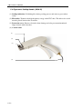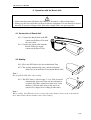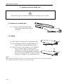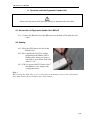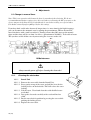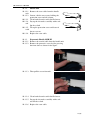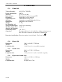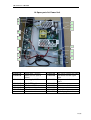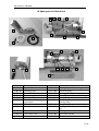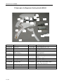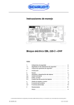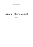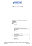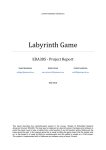
1
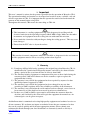
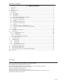
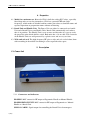
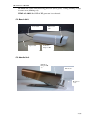
Biosealer CR 4 AA
including
Bench Unit
Manual Handle
Ergonomic Handle MSH-III
User’s Manual
and
Technical reference
Ljungberg & Kögel AB
Rev 2012-11-09
CR 4 AA User’s Manual
1. Important
This user’s manual is written for the person responsible for the operation of Biosealer CR 4.
The operational methods and routines are developed and tested to ensure a reliable, safe and
effective operation of CR 4. It is important that the operator has studied and understood the
contents of this manual before using CR 4.
Throughout this manual, CR4 means the same thing as CR4 AA.
• This instrument is a sealing equipment using radio frequency for welding and the
electrical emission at the operating frequency 40.68 MHz is high. Make sure that other
instruments and equipment near the sealing unit can withstand this emission.
• Never touch the electrodes with your fingers during the sealing process! This may cause
burn damages!
• Ensure that the PVC tube is dry on the surface.
CR4 contains electronic components which are classified as dangerous for the environment
and the equipment must be left to a recycling station when disposed.
2. Warranty
2.1. Ljungberg & Kögel AB, hereby guarantees the original buyer that Biosealer CR 4 is
manufactured in a professional and quality manner, and will be free from all faults
during a period of one year from the date of delivery from L&K.
2.2. The warranty includes equipment or components that prove to have faults during the
warranty period. L&K will without cost for the customer, repair or replace the
equipment that is faulty.
2.3. The warranty is not valid if the equipment has been repaired by anyone else than
qualified personnel, approved by L&K.
2.4. The warranty is not valid if the equipment has been changed in any way that
according to L&K:s opinion, affects the reliability or stability of the instrument.
2.5. The warranty is not valid when the serial number has been changed, crossed over or
been removed, or if the fault has been caused by misuse or abnormal use.
2.6. In these cases L&K or L&K:s representative will inform the customer about the
decision, and if wished by the client will repair the equipment for normal rate. An
estimated price can be given on request.
Abelko Innovation is committed to develop high-quality equipment and technical services to
all our customers. We welcome any inputs on technical issues that are encountered so that
they can be resolved quickly and in the most appropriate manner. Please submit your
comments/feedbacks through your local distributors or alternatively email us directly at
[email protected]
2 (20)
CR 4 AA User’s Manual
3. Table of contents
1.
2.
3.
4.
5.
Important .............................................................................................................................................. 2
Warranty ............................................................................................................................................... 2
Table of contents .................................................................................................................................. 3
Properties .............................................................................................................................................. 4
Description ........................................................................................................................................... 4
5.1. Power Unit .................................................................................................................................... 4
5.2. Bench Unit .................................................................................................................................... 5
5.3. Handle Unit. ................................................................................................................................. 5
5.4. Ergonomic Sealing Handle (MSH-III)......................................................................................... 6
6. Operation with the Bench Unit ............................................................................................................. 7
6.1. Connection of Bench Unit ............................................................................................................ 7
6.2. Sealing .......................................................................................................................................... 7
7. Operation with the Handle Unit ............................................................................................................ 8
7.1. Connection of Handle Unit ........................................................................................................... 8
7.2. Sealing .......................................................................................................................................... 8
8. Operation with the Ergonomic Handle Unit ......................................................................................... 9
8.1. Connection of Ergonomic Handle Unit MSH-III......................................................................... 9
8.2. Sealing .......................................................................................................................................... 9
9. Adjustments ........................................................................................................................................ 10
9.1. Change to manual timer .............................................................................................................. 10
10.
Maintenance ................................................................................................................................... 10
10.1.
Cleaning the electrodes. .......................................................................................................... 10
10.1.1. Bench Unit .......................................................................................................................... 10
10.1.2. Handle unit ......................................................................................................................... 11
10.1.3. Ergonomic Handle MSH-III ............................................................................................... 11
11.
Technical description...................................................................................................................... 12
12.
Trouble shooting ............................................................................................................................. 13
13.
Technical data................................................................................................................................. 14
13.1.
Power Unit .............................................................................................................................. 14
13.2.
Bench Unit .............................................................................................................................. 14
13.3.
Handle Unit ............................................................................................................................ 14
13.4.
Ergonomic Handle Unit .......................................................................................................... 14
14.
Spare parts list Power Unit ............................................................................................................. 15
15.
Spare parts list Handle Unit ............................................................................................................ 16
16.
Spare parts list Bench Unit ............................................................................................................. 17
17.
Spare parts list Ergonomic Sealing Handle MSH-III ...................................................................... 18
MDD Declaration ....................................................................................................................................... 19
Rev history
2011-11-08 TI Ergonomic handle MSH3 included
2011-11-28 TI Coiled cable Ergo Handle changed part number
2011-12-08 TI Spare parts added 2-pole contact
2012-11-09 JA Added Abelko Innovation commitment concerning technical feedback
2012-12-13 JA Minor changes in the chapter layout
2012-12-13 DC Partlist updated with 5.1
2013-01-05 DC Type in DoC updated to Biosealer
2014-04-17 DC Address in DoC updated, Added explanation that CR4 is the same as CR4 AA
2014-05-07 DC RoHS added in DoC
3 (20)
CR 4 AA User’s Manual
4. Properties
4.1. Model for continuous use. Biosealer CR 4 is built for sealing PVC-tubes, especially
blood bags tubes or sets for plasmaferes. CR 4 has a powerful HF-unit (high
frequency), which makes it suitable both for routine procedures at donation rooms and
repeated operations at preparation rooms without overheating.
4.2. Bench Unit and Handle Unit. The Power Unit can either be connected to a handle
Unit and a Bench Unit or two Handle Units. Bench Unit automatically seals when a
tube is in position. The Handle Unit is easy to move and therefore it is easy to reach
the part of the tube which shall be sealed. Both units has a 1,9 m cable. The electrodes
of the Handle Units are well protected by a plastic cover and are easy to clean.
4.3. Wide and safe seal. The high frequency HF gives a wide and safe seal of about 3mm
with a marking in the middle for making it easier to pull the tubes apart.
5. Description
5.1. Power Unit
5.1.1. Connectors and indicators
HANDLE: BNC contact for HF output to Ergonomic Handle or Manual Handle
HANDLE/BENCH UNIT: BNC contact for HF output to Ergonomic or Manual
Handle or a Bench Unit.
SIGNAL CABLE: Signal output for controlling the Bench Unit electromagnet
4 (20)
CR 4 AA User’s Manual
STATUS: BI-colour LED indicating power on (fixed green), sealing (blinking orange)
or some error (blinking red).
TEMP ALARM: Red LED if HF generator is overheated.
5.2. Bench Unit
Inlet for the
tube
Coax cable
Signal cable
Indication
lamp for HF
5.3. Handle Unit.
Indication
lamp for HF
on
Electrodes
Protection
cover
5 (20)
CR 4 AA User’s Manual
5.4. Ergonomic Sealing Handle (MSH-III)
(1) Sealing indication. Is blinking blue during sealing process and turns to green when
ready.
(2) Electrodes. Transfers the high frequency energy to the PVC tube. The tube to be sealed
must be placed between the electrodes.
(3) Protection cover. Protects electrodes from damage and also prevent unintentional
finger contact with electrodes.
(4) Coaxial cable
(1)
(2)
(3)
(4)
6 (20)
CR 4 AA User’s Manual
6. Operation with the Bench Unit
•
•
Always turn the power off before you connect or disconnect a cable or both cables.
Always use the coax cable that is delivered with the equipment. It is not allowed to extend
the cable. If you need a longer cable, then order a longer cable, see spare parts list.
6.1. Connection of Bench Unit
6.1.1. Connect the Bench Unit to the HFcontact on the Power Unit with
the coax cable.
6.1.2. Connect the signal cable from the
Bench Unit to the signal
contact on the Power Unit.
6.2. Sealing
6.2.1. Place the PVC-tube in the slot of the Bench Unit.
6.2.2. The sealing automatically starts, and the indication
diodes are lit on the Power Unit and the Bench Unit.
Note !
Do not pull the PVC-tube when sealing.
6.2.3. The PVC-tube is sealed in appr. 1-2 sec. The electrodes
automatically release the tube and the indication is
switched off. CR4 is adjusted for tubes of 4-5 mm
thickness. CR4 for tubes of up to 6,5 mm is on
demand. See chapter 9 for sealing of other tubes.
Note !
When sealing the PVC-tube on two or more places the distance between the seals must be
more than 50 mm. Shorter distance may cause leakage.
7 (20)
CR 4 AA User’s Manual
7. Operation with the Handle Unit
Always turn the power off before you connect or disconnect the coax cable.
7.1. Connection of Handle Unit
7.1.1. Connect the Handle Unit to the HFcontact on the Power Unit with the
coax cable.
7.2. Sealing
7.2.1. Place the PVC-tube in the slot of the Handle Unit.
7.2.2. Press the Handle Unit. The sealing indication on
both the Power Unit and Handle Unit is lit.
7.2.3. The PVC-tube is sealed in appr. 1-2 sec. The PVCtube is sealed in appr. 1 sec. Wait a short
moment (0.5 sec) after the indication is turned
off to let the seal cool down before releasing the
tube. CR 4 is adjusted for PVC-tubes of 4-5 mm
thickness. See chapter 9 for sealing other tubes.
Note !
When sealing the PVC-tube on two or more places the distance between the seals must be
more than 50 mm. Shorter distance may cause leakage.
8 (20)
CR 4 AA User’s Manual
8. Operation with the Ergonomic Handle Unit
Always turn the power off before you connect or disconnect the coax cable.
8.1. Connection of Ergonomic Handle Unit MSH-III
8.1.1. Connect the Handle Unit to the HF-contact on the Power Unit with the coax
cable.
8.2. Sealing
8.2.1. Place the PVC-tube in the slot of the
Handle Unit.
8.2.2. Press the Handle Unit. The sealing
indication on the Handle Unit is
blinking blue during seal process
and turns to green when ready after
about 1-2 sec.
8.2.3. CR 4 is adjusted for PVC-tubes of 4-5
mm thickness. See chapter 9 for
sealing other tubes.
Note !
When sealing the PVC-tube on two or more places the distance between the seals must be
more than 50 mm. Shorter distance may cause leakage.
9 (20)
CR 4 AA User’s Manual
9. Adjustments
9.1. Change to manual timer
Note! This is an operation which must be done by an authorized technician. We do not
recommend manual timer settings since this can lead to overheating the HF generator or the
electro magnet in the Bench Unit. It should only be used when sealing very special tubes.
If in doubt contact Ljungberg&Kögel before thi settings.
If you have hard sealed tubes that needs longer timer i.e. more time for the high frequency,
you can disconnect the automatic state by turning the potentiometer TP2 on the timer PC
board clockwise with a small screwdriver. Turning it more than 20% turns on the manual
timer and the timer will be set from 2 to 10 sec. (potentiometer 20-100%). To be able to locate
TP2 you have to lift off the cover by unscrewing the 4 screws on the side.
TP2
10. Maintenance
Always turn the power off before cleaning the electrodes !
10.1.
Cleaning the electrodes.
10.1.1. Bench Unit
10.1.1.1. Remove the coax-cable from the Bench Unit.
10.1.1.2. Press gently on top of the cover and pull the lever for the
locking device on the backside. This will release the cover
locking.
10.1.1.3. Lift the cover. Clean both electrodes with distilled water
or alcohol.
10.1.1.4. Dry up the electrodes carefully with a soft and lint-free
cloth.
10.1.1.5. Put the cover back in position by pressing the cover while
pushing the locking device.
10.1.1.6. Replace the coax cable.
10 (20)
CR 4 AA User’s Manual
10.1.2. Handle unit
10.1.2.1. Remove the coax-cable from the handle
unit.
10.1.2.2. Loosen a bit the two screws holding the
protection cover and tilt it down.
10.1.2.3. Clean both electrodes with distilled water.
10.1.2.4. Dry up the electrodes carefully with a soft
and
lint-free cloth.
10.1.2.5. Tilt up the protection cover and fasten it
with
the two screws.
10.1.2.6. Replace the coax cable.
10.1.3. Ergonomic Handle MSH-III
10.1.3.1. Remove the coaxial cable from the handle unit
10.1.3.2. Remove the protective cover by first pressing
the front down as shown in the figure.
10.1.3.3. Then pull the cover forwards.
10.1.3.4. Clean both electrodes with distilled water.
10.1.3.5. Dry up the electrodes carefully with a soft
and lint-free cloth.
10.1.3.6. Replace the coax cable.
11 (20)
CR 4 AA User’s Manual
11. Technical description
CR 4 consists of a HF generator module operating at 40,68 MHz with a maximum output
power of 100W. The HF generator (HFG-01) is a complete module mounted on the backside
of CR 4 to achieve the best possible cooling. HFG-01 is provided with current, 24 V, from a
200W medical approved power supply.
Note!
Due to regulations of maximum emission (radiation) at other frequencies than 40,68 MHz the
HFG-01 module is soldered up and shall be regarded as a component. It can not and it is not
allowed to be adjusted or repaired by anyone else than the manufacturer. In the event of
malfunction of HFG-01 it must be sent to the manufacturer for repair.
The voltage that occurs during sealing may cause burn damages if someone touches the hot
electrode during the sealing process. Therefore it is absolutely necessary to turn off the power
before cleaning or service of the Handle Unit or Bench Unit.
11.1.
Sealing Function
The sealing function is controlled by the timer board mounted on the HFG. The timer board
consists of a microprocessor which governs all functions. When the Handle Unit is pressed, or
when a tube is placed in the Bench Unit the connection from the central conductor in the coax
cable to ground is released and a DC-voltage of 5 V is supplied from the timer board.
This voltage is recognized by the microprocessor on the timer board. The processor first
checks if there is any leakage of current between the electrodes, if so this indicates damp on
the tube. The limit is set to 6µA. If the value exceeds this limit, the seal is cancelled and an
indication is given by the diode STATUS which is flashing red indicating “Moist on tube”.
There will also be an audible warning signal. This means that the tube is damp and that there
is a risk for sparking and leakage.
If no damp is found the HF generator is turned on. The microprocessor has an automatic
sensing algorithm which turns off the HFG when the seal is finished. After this there is a
cooling period of 500 ms to let the seal cool down and then the seal is completed and the
Status diode and the lamp on the handle are turned green and the indication on the Bench Unit
is turned off and the electromagnet releases the tube.
The temperature of the HFG is measured with a termistor mounted on the rear part and if the
temperature exceeds an alarm set level of 75 °C the start of sealing is cancelled and the red
diode ”Temp Alarm” is blinking.
If the electrodes are shortened during sealing the HF-generator immediately is stopped.
12 (20)
CR 4 AA User’s Manual
12. Trouble shooting
Do not adjust the electrodes by yourself. They can be damaged by erroneous performed
adjustment.
Sealing does not start and the diode ”Status”
is not blinking when the handle is pressed.
• Test another handle.
• Change the coax cable
The diode ”Status” is blinking orange but not • Test another handle.
the lamp on the handle or the Bench Unit.
• Test another Bench Unit
• Change the coax cable
• Change the HF-generator. (Only for service
personnel).
The diode ”Temp Alarm” is lit and sealing
does not start.
• The HF-generator is overheated. Let it cool
down until the alarm is turned off.
The diode ”Status” flashes red and sealing
does not start.
Sparks appear by the electrodes during
sealing.
• The tube is damp, dry it.
• This can happen if the electrodes are
overheated due to too many seals in a short
time. Let the electrodes cool down.
Sparks appear by the electrodes during
• If there has been a leakage and flashes have
sealing.
created carbon particles on the electrodes,
these particles must be removed
completely before sealing can continue.
Sparks appear by the electrodes during
• It can indicate that the electrodes are not
sealing.
parallel. Contact service personnel.
The seal is done but with bad quality, leakage • Check that the coax cable is the right type,
may appear.
the length must be 1.9 m for the Bench
Unit and the Manual Handle. The
Ergonomic Handle must have the coiled
cable. Note! The cables must not be
shortened or lengthened.
Short-circuit is shown on display or Status is • The electrodes are getting hot and the tubes
blinking red during a seal, blue lamp is turned
melts easier which may cause the
off.
electrodes to shorten during sealing. Let
the electrodes cool down by pausing for
10-15 minutes.
13 (20)
CR 4 AA User’s Manual
13. Technical data
13.1.
Power Unit
Voltage demands:
Power consumption:
Net fuses:
Internal fuses:
Frequency:
Output HF power:
Seal time:
Dimensions:
Weight:
Rel. Humidity incl.
storage and transport:
Working temperature:
Storage- and transportation temperature:
Operation:
90-250 VAC 50/60 Hz
200 VA
2x T 3,15A L 250V
Protection for high current, type PTC
40,68 MHz crystal controlled
100W/50Ω maximum power
Automatic or manually adjustable 2-10 sec
290x205x85 mm (LxWxH)
2.1 Kg
10-95% not condensing
10-40 ºC
-40- +70 ºC
Recommended max 1 seal each 3rd sec during continuous use or
max 150 seals in sequence and after that 15 minutes rest.
Protective classification: Protection against electrical shock: Class I type B.
13.2.
Bench Unit
Dimensions:
Weight:
Length of cable:
150 (L) x 60 (W) x 73(H) mm
0.9 Kg
1.9 m (4.3 or 9.1 m is available as option)
13.3.
Handle Unit
Dimensions:
Weight:
Length of cable:
206 (L) x 27 (W) x 35 (H) mm
0.3 kg
1.9 m (4.3 or 9.1 m cable is available as option)
13.4.
Ergonomic Handle Unit
Dimensions:
180 (L) x 35 (W) x 145 (H) mm
Weight:
0.220 kg
Length of cable:
Straight cable 1.74m
14 (20)
CR 4 AA User’s Manual
14. Spare parts list Power Unit
12
11
1
2
3
10
9
4
15
8
5
13
6
7
9-50401-00
9-50402-00
9-50403-00
Bottom plate (chassis)
Rubber feet x 4 (Not in
picture)
Power supply 200W
9-50404-00
9-50405-00
9-50406-00
9-50407-00
20-pole FFC cable
Front board CR5
Signal contact bench unit
Internal coax cable
9-50408-00
9-50409-00
9-50410-00
9-50411-00
9-50412-00
9-50413-00
9-50414-00
9-50415-00
24V power contact incl cable
Bench unit internal signal
cable
HF generator incl. timer
board
Mains inlet
Mains internal cable
Ferrite core φ 29mm
Cover (Not in picture)
2-pole input power contact
15 (20)
CR 4 AA User’s Manual
15. Spare parts list Handle Unit
15
1
6
14
10
11
9
5
4
2
8
9-32401-00
9-32402-00
9-32403-00
9-32404-00
9-32405-00
9-32406-00
9-32408-00
9-32409-00
9-32410-00
9-32411-00
9-32413-00
9-32414-00
9-32415-00
9-32416-19
9-32416-42
9-32416-91
16 (20)
3
16
13
Cover
BNC chassis female contact
Switch mom close
Internal coax cable
Coil incl. delrin core and dim glowing lamp
Dim glowing lamp
Plate spring
Handle
Chassis
Pin
Rubber tile
Electrode house complete
Electrode cover
Coax cable 1.9m
Coax cable 4.2m
Coax cable 9.1m
CR 4 AA User’s Manual
16. Spare parts list Bench Unit
5
6
19
12
7
1
8
11
21
10
9
2
14
18
13
4
15
3
16
22
17
20
9-33401-00
9-33402-00
9-33403-00
9-33404-00
9-33405-00
9-33406-00
9-33407-00
9-33411-00
9-33412-00
9-33413-00
9-33414-00
9-33415-00
9-33416-00
9-33417-00
9-33408-00
9-33409-00
Cover
Signal cable
Locking device
Chassis BNC contact
Hot moving electrode
Fixed electrode
Circuit board for
connections
Solenoid
Chassis
9-33410-19
9-33410-42
9-33410-91
Coax cable 1.9m
Coax cable 4.2m
Coax cable 9.1m
9-33420-00
9-33421-00
9-33422-00
9-33418-00
9-33419-00
Micro switch
Welding house chassis complete
Pull back spring
Steering pin complete
Pin compl. with cases and locking nut
Clamp spring
Piston complete incl. coil and dim
glowing lamp
Dim glowing lamp
Welding house cover, micro switch
side
Welding house cover
Coax cable internal
HF-cable flexible
17 (20)
CR 4 AA User’s Manual
17. Spare parts list Ergonomic Sealing Handle MSH-III
15
11
1
13
12
4
14
9
10
6
5
8
2
7
3
16
17
18
19
9-35401-00
9-35402-00
9-35403-00
9-35404-00
9-35405-00
9-35411-00
9-35412-00
9-35413-00
9-35414-00
9-34515-00
Pushing spring
Piston complete incl. coil
Moving electrode
Fixed electrode
PC board complete incl. micro switch
(Not in picture)
9-35405-01
9-35406-00
Right cover
Left cover
Handle
Protection cover
Internal coax cable with
SMA contact
Washer for SMA contact
Indicator lens
9-34516-00
9-35407-00
9-35408-00
9-35409-00
Screen plate bottom
Screen plate top
Pushing knob
9-35417-00
9-35418-00
9-35419-16
3 Socket head cap screw for screen
plates
Screw Torx T25x8
Screw Torx T30x8
Coax cable coiled, BNC-SMA
175cm (Not in picture)
9-35410-00
Pull back spring
18 (20)
MDD Declaration
DECLARATION OF CONFORMITY
according to the
Medical Devices Directive 93/42/EEC
and
RoHS directive, 2011/65/EU
STANDARDS TO WHICH CONFORMITY IS DECLARED:
EN 60 601-1 Safety
EN 60 601-1-2 EMC
Including: EN 55011 Kl B, EN 61000-4-2, EN 61000-4-3, EN 61000-4-4, EN 61000-4-5
Manufacturer:
Address:
Telephone:
Telefax:
Abelko Innovation
972 54 Luleå
+46 920-220360
+46 920-220068
Marketing:
Address:
Telephone:
Telefax:
Ljungberg&Kögel AB
Box 1032, 251 10 Helsingborg
+46 042-139860
+46 042-132181
Type of Equipment:
Model:
Product class:
Biosealer
CR4 AA
Class 1
I, the undersigned, hereby declare that the equipment specified above conforms to the above
Directive and Standards.
Date of issue: 7 May 2014
/ Thommy Lundström
Position/title: President
CR 4 AA User’s Manual
Ljungberg & Kögel AB