1
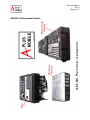
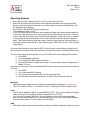
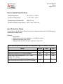
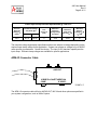
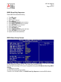
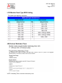
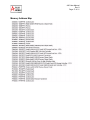
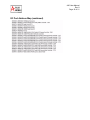
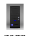
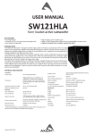
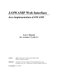
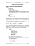
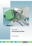
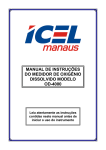
A20-MC Hardware Manual
Rev 8
Release Date: July 15, 2008
A20 User Manual
Rev 8
Page 2 of 21
Table of Contents
A20-MC Theory of Operation
page 3
Glossary of Abbreviations
page 3
A20-MC 3-Dimensional Images
page 4
Key Switch
page 5
Start Up Sequence
page 5
Operating Systems
page 6
Environmental Specifications
page 7
Input Protection Clamp
page 7
APM-I/O Connector Cable
page 8
Input Voltage Considerations
page 9
Battery System Capabilities
page 9
Operation
page 10
Repairs
page 10
Frequently Asked Questions
page 11
Outline Drawing
page 13
Custom Connector Pin Out
page 14
BIOS Reset Key Sequence
page 15
BIOS Video Setup Screen
page 15
LCD Monitor Panel Type BIOS Setting
page 16
A20 System Watchdog Timer
page 16
Memory Address Map
page 17
I/O Port Address Map
page 18
IRQ
page 20
DMA
page 20
Aplus Mobile Contact Information
page 21
A20 User Manual
Rev 8
Page 3 of 21
A20-MC Theory of Operation
You will notice that this computer doesn’t crash except when software is buggy. That is because
the CPU and system ALWAYS has clean power available. It knows when you have main power
or not and if the computer is running or not. If you turn the computer off through the Windows
shutdown box on the main screen and the main power is still up, the A20 will just reboot the system in a few seconds. Conversely, if the system senses the main power is down, after a short
delay, it will shut down Windows orderly as if you had shut it down yourself. The A20 system will
go to sleep waiting for main power to come back up for a few seconds and then it will boot again.
It will finish booting no matter what the power state and then check main power again to see if it
needs to stay up or it needs to shutdown Windows.
Glossary of Abbreviations
A20-DH
Aplus Mobile Harsh Remote Drive Interface with DVD/RW Slot
Load Drive and USB Ports
A20-HH
Aplus Mobile Harsh USB 2.0 Hub, Aluminum Chassis
A20-MC
Aplus Mobile Harsh Environment DC Powered Computer
APM-I/O
Aplus Mobile Input/Output Cable
BIOS
Basic Input Output System
BV
Breakdown Voltage
CF
Compact Flash
CPU
Central Processing Unit
DSK
Disk
HD
LED
OS
Hard Drive
Light Emitting Diode
Operating System
PWR
Power
SATA
Serial-ATA
UPS
Uninterruptible Power Supply
USB
Universal Serial Bus
A20 User Manual
Rev 8
Page 4 of 21
A20-MC 3-Dimensional Images
A20 User Manual
Rev 8
Page 5 of 21
Key Switch
To turn the computer on, turn key counterclockwise to ON position. Key can be removed in
either position.
The key switch is a true power disconnect. When the key is in the OFF position, the computer is
physically disconnected from the outside world and internal UPS battery. When the computer is
OFF, the computer cannot be powered.
Cautions:
DO NOT USE KEY TO TURN A20-MC ON OR OFF. Key is used for connecting or disconnecting power only. Use power supply to turn A20-MC ON or OFF.
Do not leave the KEY in the ON position while not in use for extended periods. Extended
periods could be defined as 5 days or more. This time may be shortened depending on
temperature and age of the battery. Leaving the key switch ON leaves the battery engaged
and will discharge the battery over time. When not in use, turn key clockwise to OFF position.
Start Up Sequence
1.
2.
3.
4.
5.
Connect peripheral cables required for your application.
Connect unit to DC power source.
Turn key counterclockwise to ON position.
Apply DC power to turn unit ON.
Red PWR LED should come ON and depending on your configuration, yellow UPS LED may
flash detecting UPS or may remain OFF indicating power system status good.
6. If the yellow UPS LED is quickly flashing or if the blue CPU LED is quickly flashing, then the
power system has identified an error and requires a reboot in the form of power cycling.
7. During normal operation, if the main power as indicated by the red PWR LED is interrupted,
the yellow UPS LED will come ON to indicate UPS status is active.
8. The green DSK LED may remain lit or may flash indicating disk activity depending on HD or
SATA configuration.
A20 User Manual
Rev 8
Page 6 of 21
Operating Systems
•
•
•
•
•
Some OS will require disabling the CF or HD in order to load your OS.
Some OS will require the boot order & HD configuration screens to be set up specifically.
Please consult your software literature or you may need to try several configurations if your
OS hangs during installation.
Enter BIOS by hitting DELETE key during boot up.
The motherboard type is LV677.
If your OS hangs during normal shut down sequence, please cycle power with key switch or
unit will force the OS to shut down after a period of time and kill all system power. This is in
order to save the UPS battery from excessive UPS discharge. If this is the case, it is normal
to expect high inrush current when you turn it back ON due to the UPS battery’s depleted
state. This will be limited by the power control, which may go into pulse charge condition to
limit peak currents during this time. Slow flashing yellow UPS LED is normal. This indicates
pulse charge.
You must select hard drive boot order in BIOS. You must move your boot device to the front of
the list on the boot order screen as well as setup the typical boot order in the Main BIOS screen.
You will need to setup the configuration for your CF & SATA HD in the following BIOS screens.
a. Go to BIOS
b. Go to Integrated Peripherals
c. Go to OnChip IDE Device and press Enter
d. See the Boot Device Configuration Screen. You may choose system configuration or
disable CF here.
Next setup your boot drive order on a different BIOS screen and move your boot drive to the top
of the list.
a. Go to BIOS
b. Go to Advanced BIOS Features
c. Go to (2nd choice) Hard Disk Boot Priority and press Enter
d. See selection of Boot Drives and move your Boot Drive to the top of the list.
Windows
• With Windows pre-loaded on your machine, the Administrator password is: “aplusmobile”
• The CF is disabled in BIOS. It is a SLAVE on IDE1. Please go to BIOS to enable if used.
Linux
• The CF will be disabled in BIOS. It is a MASTER on IDE1. If you require a different configuration to load your OS, please alter BIOS configuration for CF & HD.
• You may need to disable SATA HD if you are loading your OS on CF during installation.
Also, you may need to disable CF if you are loading your OS on SATA HD during installation.
You may enable either CF or HD after your OS is loaded.
QNX
• QNX may not shut down properly and hang. Check your QNX configuration if this is an issue.
A20 User Manual
Rev 8
Page 7 of 21
Environmental Specifications
Storage Temperature
-20 ~ 85°C (-4 ~ 185°F)
Operational Temperature
0 ~ 60°C (32 ~ 140°F)
Storage Shock (half sine wave)
1000 G / 1 ms
Operational Shock (half sine wave)
300 G / 2ms, 160G / 1ms
Input Protection Clamp
This unit has an input protection clamp to protect from voltage transients induced by lightning and
other transient voltage events.
Features
•
•
•
•
Bi-directional
5000W Peak Pulse Power capability on 10/1000µS waveform
Repetition rate (duty cycle): 0.05%
Response time: typically less than 1.0pS from 0 Volts to BV
Power Input Clamp Maximum Ratings and Characteristics @ 25°C Ambient Temperature
Rating
Symbol
Value
Unit
Peak Pulse Power Dissipation on 10/1000µS waveform
PPPM
Min 5000
Watts
Peak Pulse Current of on 10/1000µS waveform
IPPM
129
Amps
PM(AV)
8
Watts
IFSM
400
Amps
Steady State Power Dissipation at TL=75°C, Lead
Lengths .375”, (9.5mm)
Peak Forward Surge Current, 8.3mS Single Half SineWave Superimposed on Rated Load, (JEDEC Method)
A20 User Manual
Rev 8
Page 8 of 21
Power Input Clamp Electrical Specification @ TAMB 25°C
Reverse
Stand off
Voltage VR
(Volts)
24.0
Breakdown Voltage
VBR (Volts) @ IT
MIN
MAX
26.70
29.50
Test
Current IT
(mA)
Maximum
Clamping
Voltage VC @
IPP (Volts)
Maximum
Peak Pulse
Current IPP (A)
Maximum
Reverse
Leakage IR @
VR (µA)
5
38.9
129.0
10
The transient voltage suppression specifications above are subject to change depending on the
required input clamp voltage for the application. System can operate on voltages of up to 48VDC
under special circumstances. Consult the factory. The input is 60V transient capable past the
input clamp. Different clamp voltages are available for specific applications.
APM-I/O Connector Cable
STEREO
AUD-OUT
AMP-I/O
MIC IN
VIDEO CAPTURE IN
COMP
S-VIDEO*
*COMP Y C
The APM-I/O connector cable will bring AUDIO-OUT, MIC-IN and other options as specified in
your system configuration, such as Video Capture.
A20 User Manual
Rev 8
Page 9 of 21
Input Voltage Considerations
Nominal Operational Voltages
12 - 29VDC
Operational voltages
0 - 30VDC (System runs on Internal UPS under 12V)
Your unit may have a different input clamp depending on your application.
The A20-MC power system is capable of regulating up to 60VDC, however this presents excessive power dissipation and is not recommended. This power front end also provides a
+60 / -50VDC transient capability along with reverse battery protection and electronic fuse. You
must provide an additional fused input to the unit for a catastrophic event. 10 - 20A fuse should
be sufficient to prevent false tripping.
Even though the A20-MC is fused internally, you must provide an additional 10 - 20A fused
input.
The unit may exhibit pulse charging continuously if ran at low line voltage (12.0VDC) due to current availability on the main power line.
If mounting more than one system, please connect the power cable directly to the battery or main
switch from battery in a star configuration to reduce power loss.
Battery System Capabilities
Replace with Panasonic LC-R121R3P battery only. Seal cover with GE RTV-133 or sensor safe
silicone only.
The battery is a sealed lead acid, non-spillable gel cell and is certified for air shipment. The battery uses a solid gel matt electrolyte and is available from Panasonic distributors. This is the
same type of battery that is used in emergency lights.
A20 User Manual
Rev 8
Page 10 of 21
Operation
•
•
•
•
•
•
•
Applying power will turn ON the computer and boot your OS automatically.
Power control system is always checking for the presence of main power and if the computer is running.
If main power is present, the power control will check to see if the OS is booted. If not, it will attempt
to boot OS. If it is unsuccessful after 25 attempts, the power control will put the system to sleep and
you must cycle main power in order to boot OS again.
If the power control senses main power is down for 8-14 seconds continuously, then it will initiate OS
shutdown on UPS power.
If main power comes back anytime during shutdown sequence and before it goes to sleep, it will
attempt to reboot OS without requiring you to recycle the power. Power recycling is only required if
system is fully asleep, otherwise the system will be fully automatic and should not require power
cycling during normal operation. This is a rare situation.
Once system has shutdown and gone to sleep (all front panel LEDs OFF), you must cycle main
power to reboot system.
The system will always try to boot OS if main power is present at any time, except when system has
gone fully to sleep (i.e.: all front panel LEDs are OFF).
1. Turn ON main power.
2. System will boot itself and remain ON until main power is turned OFF.
Turning OFF main power for a short period of time will initiate OS shutdown on UPS and sleep mode.
Do not use the key switch to turn the unit ON and OFF. This will disconnect the UPS from the computer
and will cause the computer not to shut down properly.
Repairs
The A20 is a sealed case and is very difficult to open. It is not recommended. All repairs should be done
at the Aplus Mobile, Inc. factory or in extreme cases serviced by a qualified super-technician capable of
aircraft system-level work.
There are no user serviceable or replaceable parts inside the system. The CPU cannot be replaced
without total disassembly of the case. Please consult the factory for any upgrades.
A20 User Manual
Rev 8
Page 11 of 21
Frequently Asked Questions
Q: What is the bottleneck that seems to limit us to 3 Gig of available RAM even though 4
Gig is installed?
A: It is the chipset's address limitations. The processor is capable. However Intel's mobile
chipset has not caught up yet. We should see this in the next chipset release. It has been
unclear when this bottleneck is going to be removed. We had anticipated that with the introduction of the Core 2 Duo, we would see a chipset upgrade as well, but it hasn't quite happened yet.
Since there are no such things as 1.5GB memory modules, we have to use 2GB memory modules and charge accordingly. Intel is aware of this.
Q: The system settings indicate that IDE 1 slave is a Transcend 2 Gig device. Is this a normal configuration for these things? Are most of your other customers using this CF drive
as a boot device?
A: Yes. The 2GB CF is standard in all systems and can be upgraded to 4GB or 8GB as required.
The Linux customers are using this as a boot device but you do not have to. It's simply there for
your convenience. You may disable it in BIOS if you like. It is blank as delivered from the factory.
Q: Should I assume that there is no data on this CF device and go ahead and format it?
A: Yes. It is already formatted from the factory but you may format it any way you like. Also, the
hard drive is raw and not formatted to avoid hassles between disk format variations.
Q: The A20-MC spec sheet indicates that there are three external USB 2.0 ports but I only
see two. Am I missing something or do we only have two ports due to some other configuration choice?
A: Yes. The third port will come out of the APM-I/O connector and it is used for specific applications. Typically, customers will plug any standard hub into either USB port for their keyboards
and mice. You can use any standard USB hub and it will be powered as normal by either harsh
USB port. Only the A20-DH requires the APM-I/O cable for power.
Q: Since the PS/2 ports and other four USB ports are not accessible outside the case, are
most of your customers using this device a) without keyboards and mice, b) with USB
keyboards and mice (but no free USB ports) or c) with an add on USB hub for keyboard,
mouse and additional USB devices?
A: Yes, most people use this as an embedded controller and only use keyboards and mice for
initial installation. Most people will use choice c) and simply plug a hub in for other peripherals.
A20 User Manual
Rev 8
Page 12 of 21
Q: Which type of form factor are the mini-PCI ports? Are they the older mini-PCI (IA, IB,
IIA, IIB, IIIA, or IIIB) or the newer PCI express mini?
A: Mini-PCI ports are IIIB.
Q: Do the RS-232/422/485 ports eat up any of the PCI slots, or are they slotted separately?
A: RS-232/422/485 ports do not use any mini-PCI slots. Both ports are on the motherboards.
A20 User Manual
Rev 8
Page 13 of 21
Outline Drawing
A20 User Manual
Rev 8
Page 14 of 21
Custom Connector Pin Out
A20 User Manual
Rev 8
Page 15 of 21
BIOS Reset Key Sequence
Resets BIOS fail safe default setting.
1. Turn ON power
2. Wait for BEEP
3. WAIT one (1) second
4. Press DEL key
5. Press DOWN ARROW key one (1) time
6. Press RIGHT ARROW key one (1) time
7. Press RETURN key one (1) time
8. Press Y key one (1) time
9. Press RETURN key
10. Press DOWN ARROW key four (4) times
11. Press RETURN key two (2) times
12. System should reset and reboot
BIOS Video Setup Screen
Do not change Boot Display to LCD. This setting must remain on AUTO.
Set LCD Type according to LCD monitor Type panel setting (see LCD Monitor Panel Type BIOS
Setting).
TV Standard is not used.
On Chip VGA should remain enabled.
If screen is not viewable at Boot, use BIOS Reset Key Sequence to restore BIOS defaults.
A20 User Manual
Rev 8
Page 16 of 21
LCD Monitor Panel Type BIOS Setting
A20 System Watchdog Timer
NOTE: Watchdog Timer not active unless set by user.
A20 User Manual
Rev 8
Page 17 of 21
Memory Address Map
A20 User Manual
Rev 8
Page 18 of 21
I/O Port Address Map
A20 User Manual
Rev 8
Page 19 of 21
I/O Port Address Map (continued)
A20 User Manual
Rev 8
Page 20 of 21
IRQ
DMA
A20 User Manual
Rev 8
Page 21 of 21
Aplus Mobile Contact Information
Address:
Aplus Mobile, Inc.
19629 S. McCord Rd.
Oregon City, OR 97045
Contacts:
General
503-656-5759
Customer Support
503-265-9325
[email protected]
Find Aplus Mobile on the web at: www.AplusMobile.com
CAGE Code: 4P1Q1
Pronet Supplier Code: P0843918